
LP304 - Speaker YORKVILLE - Free user manual and instructions
Find the device manual for free LP304 YORKVILLE in PDF.


| Product Type | LED Dimming Light Bar / Sound Speaker |
| Brand | YORKVILLE |
| Model | LP304 |
| Number of Channels | 4 dimming channels (4 PAR cans) |
| Bulb Type | PAR56 NSP (300 W) |
| Maximum Power | 1200 W (4 × 300 W) |
| Supply Voltage | 125 VAC, 60 Hz |
| Power Consumption | 1200 W (full load) |
| Dimensions (L × W × H) | 102 cm × 41 cm × 43 cm |
| Weight | Approximately 15 kg |
| Chassis Material | Steel |
| Mounting | On 1 3/8 inch round tripod (not included) |
| Control Connector | XLR 3-pin (male and female) |
| Power Connector | Polarized grounded power plug |
| Controller Compatibility | YORKVILLE LP608 (not included) |
| MIDI Control | Yes (via LP608 controller) |
| Audio Input | Unbalanced 1/4 inch jack (on LP608 controller) |
| Main Functions | Dimming, preset scenes, black-out, lighting effects (chase, organ, flash) |
| Number of Color Filters Included | 8 |
| Warranty | 2 years (parts and labor), 10 years on cabinet |
| Country of Sale | Canada and United States |
| Maintenance | Clean with dry cloth, do not block ventilation holes |
| Safety Precautions | Plug into grounded outlet, do not expose to water, use only in dry indoor areas |
| Available Spare Parts | PAR56 NSP 300 W bulbs, XLR cables, tripod |
Frequently Asked Questions - LP304 YORKVILLE
User questions about LP304 YORKVILLE
0 question about this device. Answer the ones you know or ask your own.
Ask a new question about this device
Download the instructions for your Speaker in PDF format for free! Find your manual LP304 - YORKVILLE and take your electronic device back in hand. On this page are published all the documents necessary for the use of your device. LP304 by YORKVILLE.
USER MANUAL LP304 YORKVILLE
IMPORTANT SAFETY INSTRUCTIONS

INSTRUCTIONS PERTAINING TO A RISK OF FIRE, ELECTRIC SHOCK, OR INJURY TO PERSONS
CAUTION:
TO REDUCE THE RISK OF ELECTRIC SHOCK, DO NOT REMOVE COVER (OR BACK).
NO USER SERVICEABLE PARTS INSIDE.
REFER SERVICING TO QUALIFIED SERVICE PERSONNEL.
Read Instructions
The Owner's Manuals should be read and understood before operation of your unit. Please, save these instructions for future reference.
Packaging
Keep the box and packaging materials, in case the unit needs to be returned for service.
Warning
When using electric products, basic precautions should always be followed, including the following:
Power Sources
Your unit should be connected to a power source only of the voltage specified in the owners manual or as marked on the unit. This unit has a polarized plug. Do not use with an extension cord or receptacle unless the plug can be fully inserted. Precautions should be taken so that the grounding scheme on the unit is not defeated.
Hazards
Do not place this product on an unstable cart, stand, tripod, bracket or table. The product may fall, causing serious personal injury and serious damage to the product. Use only with cart, stand, tripod, bracket, or table recommended by the manufacturer or sold with the product.
Follow the manufacturer's instructions when installing the product and use mounting accessories recommended by the manufacturer.
The apparatus should not be exposed to dripping or splashing water; no objects filled with liquids should be placed on the apparatus.
Terminals marked with the "lightning bolt" are hazardous live; the external wiring connected to these terminals require installation by an instructed person or the use of ready made leads or cords.
Ensure that proper ventilation is provided around the appliance.
No naked flame sources, such as lighted candles, should be placed on the apparatus.
Power Cord
The AC supply cord should be routed so that it is unlikely that it will be damaged. If the AC supply cord is damaged DO NOT OPERATE THE UNIT.
Service
The unit should be serviced only by qualified service personnel.
INSTRUCTIONS RELATIVES AU RISQUE DE FEU, CHOC ÉLECTRIQUE, OU BLESSURES AUX PERSONNES
AVIS:
AFIN DE REDUIRE LES RISQUE DE CHOC ELECTRIQUE, N'ENLEVEZ PAS LE COUVERT (OU LE PANNEAU ARRIERE)
NE CONTIENT AUCUNE PIECE REPARABLE PAR L'UTILISATEUR.
CONSULTEZ UN TECHNICIEN QUALIFIE POUR L'ENTRETIENT
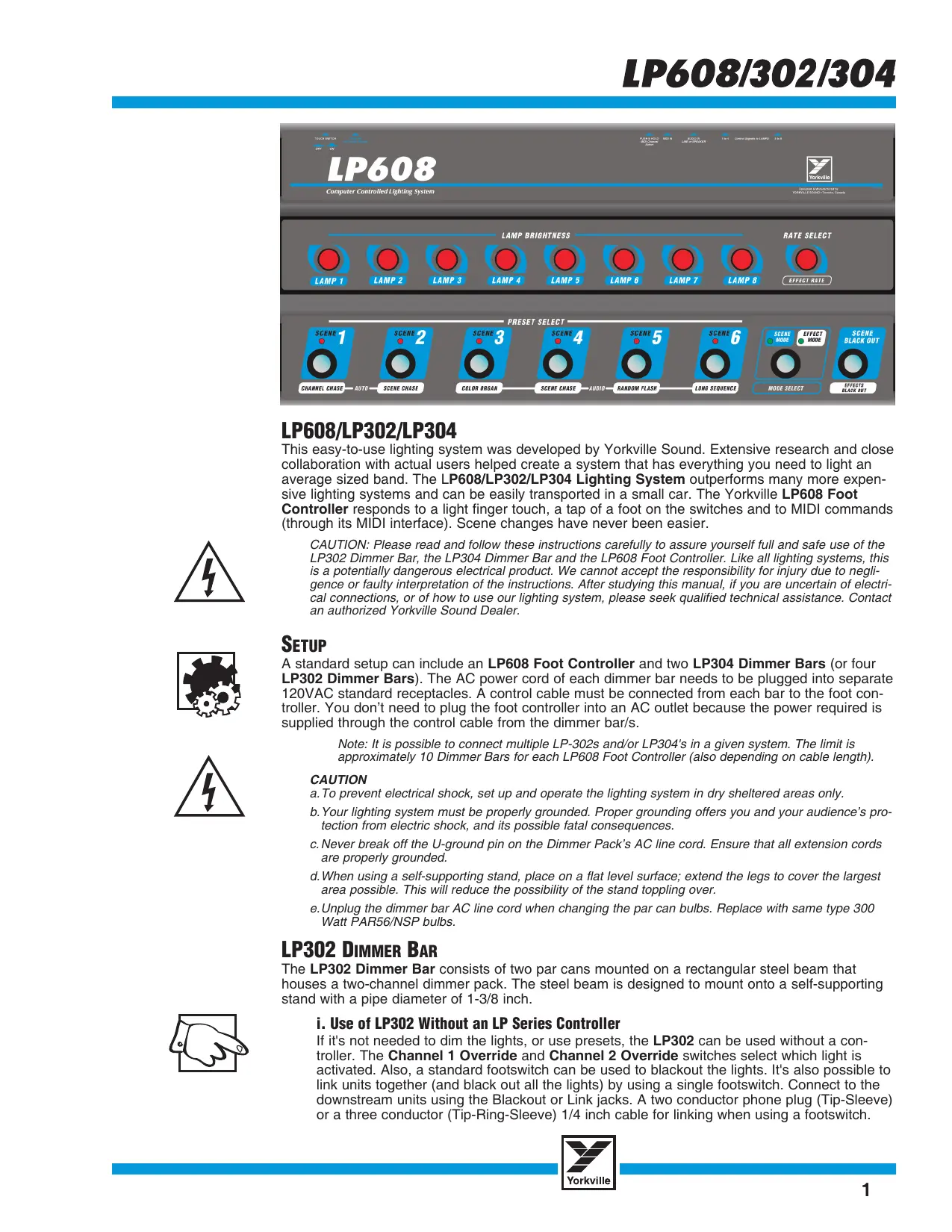
This easy-to-use lighting system was developed by Yorkville Sound. Extensive research and close collaboration with actual users helped create a system that has everything you need to light an average sized band. The LP608/LP302/LP304 Lighting System outperforms many more expensive lighting systems and can be easily transported in a small car. The Yorkville LP608 Foot Controller responds to a light finger touch, a tap of a foot on the switches and to MIDI commands (through its MIDI interface). Scene changes have never been easier.

CAUTION: Please read and follow these instructions carefully to assure yourself full and safe use of the LP302 Dimmer Bar, the LP304 Dimmer Bar and the LP608 Foot Controller. Like all lighting systems, this is a potentially dangerous electrical product. We cannot accept the responsibility for injury due to negligence or faulty interpretation of the instructions. After studying this manual, if you are uncertain of electrical connections, or of how to use our lighting system, please seek qualified technical assistance. Contact an authorized Yorkville Sound Dealer.
SETUP
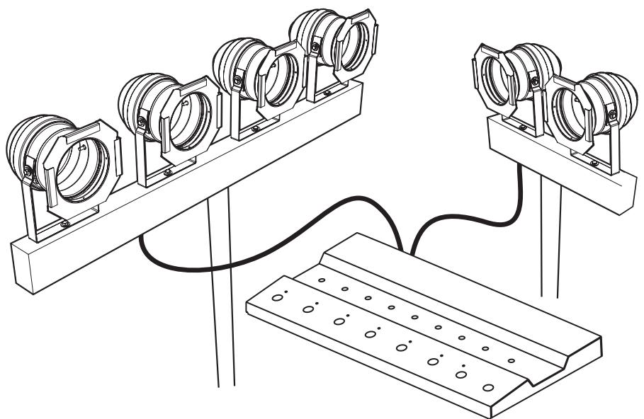
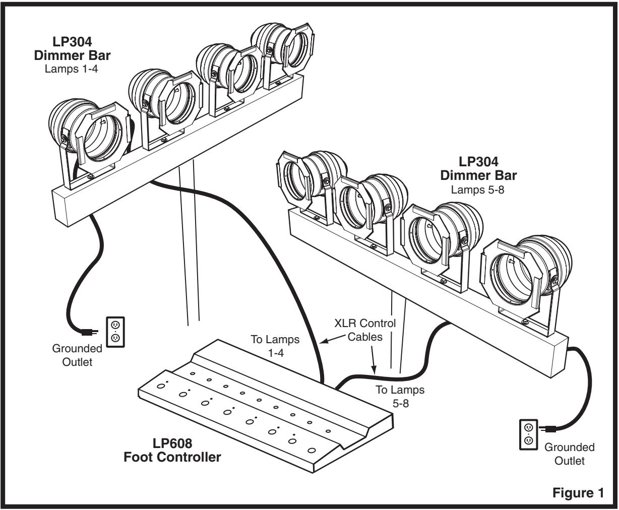
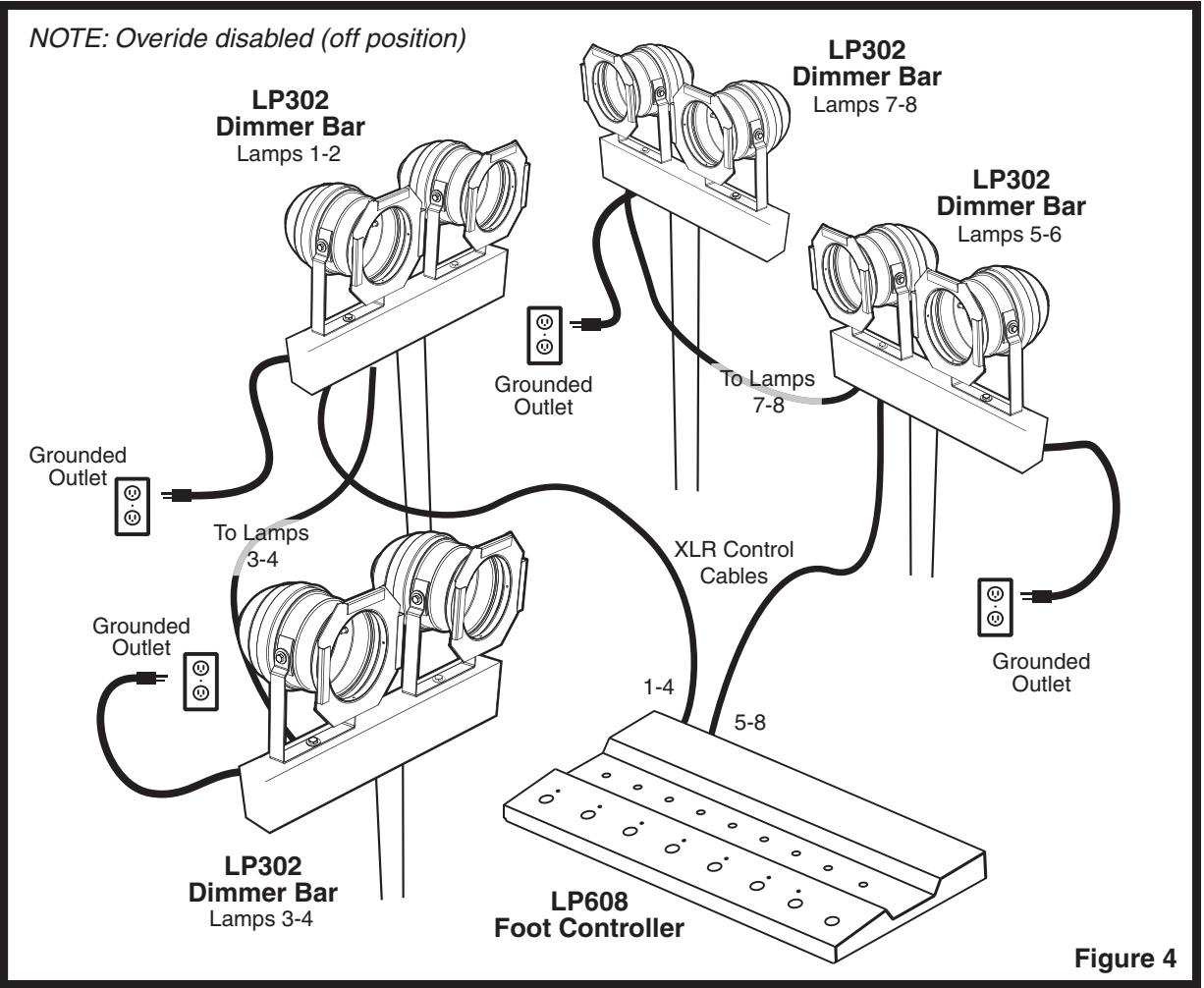
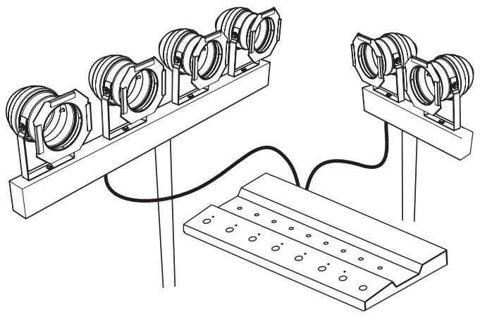
A standard setup can include an LP608 Foot Controller and two LP304 Dimmer Bars (or four LP302 Dimmer Bars). The AC power cord of each dimmer bar needs to be plugged into separate 120VAC standard receptacles. A control cable must be connected from each bar to the foot controller. You don't need to plug the foot controller into an AC outlet because the power required is supplied through the control cable from the dimmer bar/s.
Note: It is possible to connect multiple LP-302s and/or LP304's in a given system. The limit is approximately 10 Dimmer Bars for each LP608 Foot Controller (also depending on cable length).
CAUTION
a. To prevent electrical shock, set up and operate the lighting system in dry sheltered areas only.
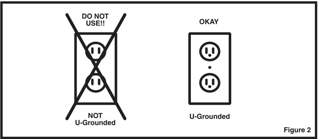
b. Your lighting system must be properly grounded. Proper grounding offers you and your audience's protection from electric shock, and its possible fatal consequences.
c. Never break off the U-ground pin on the Dimmer Pack's AC line cord. Ensure that all extension cords are properly grounded.
d. When using a self-supporting stand, place on a flat level surface; extend the legs to cover the largest area possible. This will reduce the possibility of the stand toppling over.
e. Unplug the dimmer bar AC line cord when changing the par can bulbs. Replace with same type 300 Watt PAR56/NSP bulbs.
LP302 DIMMER BAR
The LP302 Dimmer Bar consists of two par cans mounted on a rectangular steel beam that houses a two-channel dimmer pack. The steel beam is designed to mount onto a self-supporting stand with a pipe diameter of 1-3/8 inch.
i. Use of LP302 Without an LP Series Controller
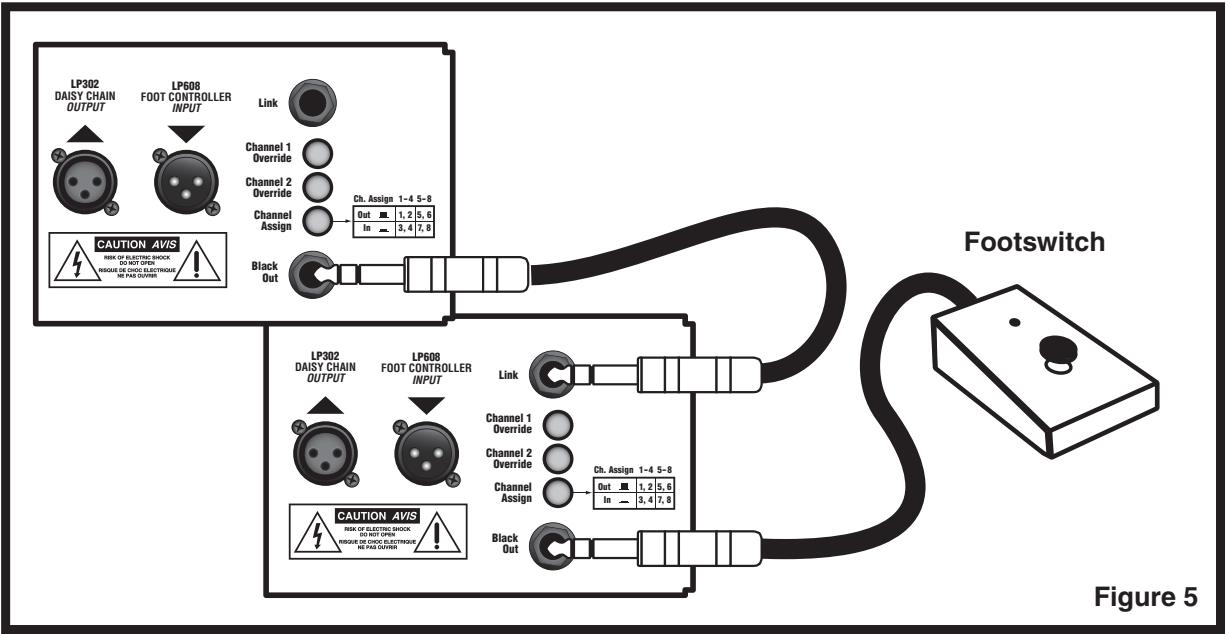
If it's not needed to dim the lights, or use presets, the LP302 can be used without a controller. The Channel 1 Override and Channel 2 Override switches select which light is activated. Also, a standard footswitch can be used to blackout the lights. It's also possible to link units together (and black out all the lights) by using a single footswitch. Connect to the downstream units using the Blackout or Link jacks. A two conductor phone plug (Tip-Sleeve) or a three conductor (Tip-Ring-Sleeve) 1/4 inch cable for linking when using a footswitch.
ii. Use of LP302 With an LP Series Controller
When used with an LP608 controller, the LP302 is enabled to dim the lights and set up presets. See Figure 5 for connection details. Daisy-chain connections using the XLR jacks must be used to link units when controlled by a LP Series controller. The 1/4 inch jacks should not be used when using the LP Series controller. It's possible to daisy-chain several units (even mixing LP302 and LP304 dimmers bars). When using a controller, the override switches should be left in the out position. For convenience, the Override switches may be used when aiming the lights.
iii. 500 Watt Lamp Conversion
The LP302 Dimmer Bar can use 500 Watt par 56/NSP lamps, just replace the 300 Watt lamps with the 500 Watt par 56/NSP lamps.
LP304 DIMMER BAR
The dimmer bar consists of four par cans mounted on a rectangular steel beam that houses a four-channel dimmer pack. The steel beam is designed to mount onto a self-supporting stand with a pipe diameter of 1-3/8 inch.
OPERATION
When the dimmer bar is initially plugged into the AC wall outlet, a lamp test program will illuminate each lamp sequentially. This will confirm that the dimmer pack microprocessor is operational.
(This test does not occur if the foot controller is connected.) The foot controller may be used to test the lights individually.
PAR CANS / GELS
Four, 300 Watt, Par 56 cans are mounted on each LP304 Dimmer Bar (two on each LP302). Each dimmer bar is factory supplied with eight colored gels. The frames to mount the gels are located at the mouth of each par can. Always operate the par cans in an open, well-ventilated area. Never obstruct the ventilation holes on the can bodies. To reduce the possibility of fire, keep flammable materials away from the can bodies.
CONNECTIONS
There are two XLR connectors (one male and one female) mounted on the back of the LP302 and LP304 Dimmer Bars. Two female XLR connectors are on the LP608 Foot Controller.
Standard XLR, shielded microphone cables are used as the controller cables. A single controller cable is connected from the foot controller female XLR to the male XLR input connector on the dimmer bar. Another controller cable can be connected to the dimmer bar female XLR output to allow a daisy-chain to additional dimmer bars. This allows connection of several dimmer bars (in parallel). Note that each dimmer bar in the chain receives the same control signal.
The LP608 Foot Controller is a very versatile lighting controller. It can be operated using your foot or hand (as well as MIDI information). Being microprocessor controlled, the system is smart, it acts upon commands that you input sequentially. This results in less setup time and fewer errors. Its heavy-duty foot switches are rugged enough to guarantee many years of reliable operation.
GETTING STARTED
The following step-by-step procedure can help get you start running your LP608/LP304/ LP302 Lighting System.
1. SETUP
Connect the controller cable (standard XLR microphone cable) from the LP608 Foot Controller's Control Signal Output to Lamps jack to the LP304 or LP302 Dimmer Bar. Use a single controller cable, from each output, on the LP608 to a LP304 or LP302 Dimmer Bar. (Figure 1)
2. TOUCH SWITCH
The LP608 Foot Controller can serve two types of users. A musician while performing, can use the foot controller on the floor, operating the unit with his feet. A sound or lighting technician can use the LP608 in touch-mode, placing the controller on a table and tapping the control switches with his hand.
3. FACTORY PRESETS
Plug the LP304 or LP302 Dimmer Bar AC into a standard wall outlet. To reset the unit, use a long narrow object (such as a screwdriver or ballpoint pen) and depress the switch labeled Push In For Factory Presets. The switch is located on the rear of the controller.
Note: The LP608 Foot Controller can be reset to the Factory Presets with or without the controller cables connected.
4. SELECTING SCENES
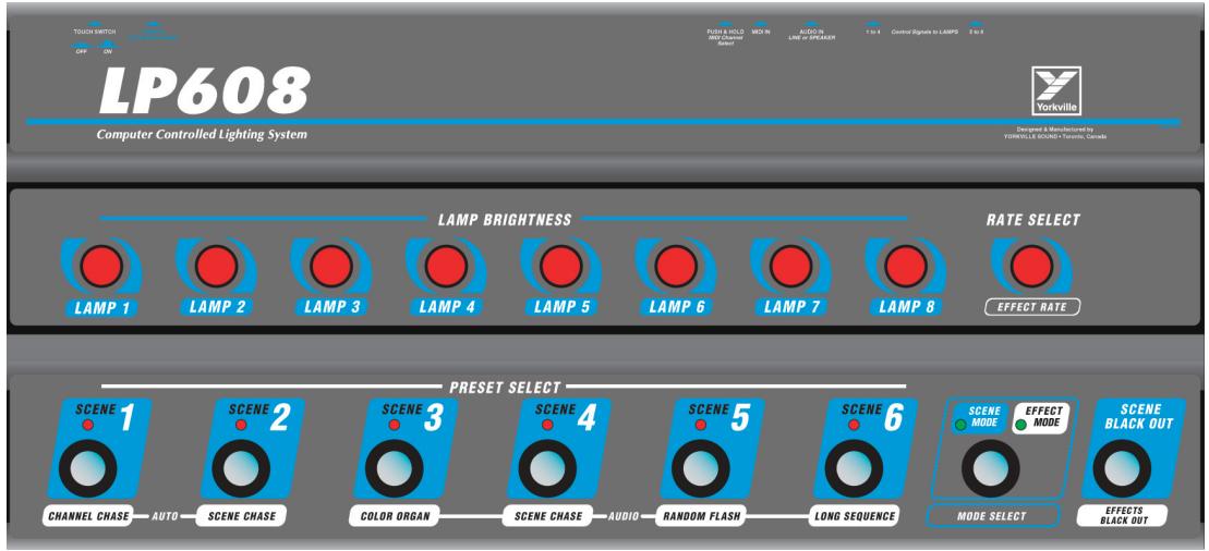
On the LP608 Foot Controller, the Scene 1 and Scene Mode lights should be illuminated. By depressing the footswitch for the corresponding scene (1-6), different combinations of the par lamps will illuminate.
5. SCENE BLACKOUT
Press the Scene Blackout footswitch on the LP608. Any lamps illuminated will turn off (blackout). Pressing the Scene Blackout switch again will return the controller to the last scene. Pressing a scene footswitch, other than the pre-blackout scene, will illuminate the lamps for the selected scene.
6. RATE SELECT
The Rate Select knobs adjusts the rate of how one scene changes to another. Turning the knob clockwise speeds the rate (decreasing the time between scenes). Counter-clockwise rotation will slow the rate and increase the time it takes to change scenes. The rate is adjustable from 0 to 10 seconds. The encoders are digital and rotate fully without need for a 'stop' detente.
7. CHANGING PRESET SCENES
The intensity and combination of lamps that are on for each scene can be easily configured. Select the scene that you wish to program using the "Scene Preset Select" push-switches. There are eight Lamp Brightness adjustment knobs located directly above the Preset Select Switches. Rotate the knobs corresponding to the lamp requiring adjustment. The Lamp Brightness knobs react in the same manner as the Rate Select controls – clockwise for increasing brightness and counter-clockwise for decreasing the brightness.
8. STORING A NEW SCENE
Every time you adjust the lamp intensities of a scene it's automatically stored.
Internal Battery Backup
The CMOS memory of the LP608 is saved as you program the controller. Two AA sized batteries are installed internally. To replace, remove the 12 screws on the bottom of the unit. Changing the batteries every year is recommended.
Note: Adjustments made to a scene will automatically erase the previously stored setup for the scene. There is no "enter" button – the system operates on a "what you see is what you get" basis.
EFFECTS
The following is a list of the six effects available on the LP608 Foot Controller and what control is used.
Effect Control
Scene Chase
Scene Chase
Internal Clock (RATE Control)
Internal Clock (RATE Control)
Colour Organ
Scene Chase
Audio Input required to drive Effect
Audio Input required to drive Effect
Random Flash
Audio Input required to drive Effect
Long Sequence
Audio Input required to drive Effect
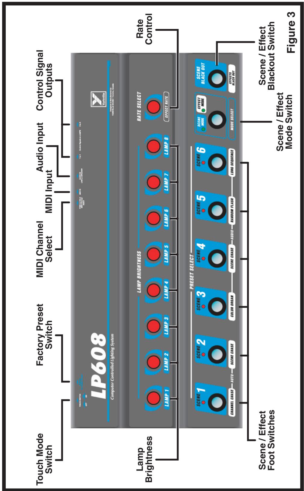
- Selection of an effect can only be achieved when the Mode Select footswitch is in the Effect Mode. (Refer to figure 3.)
- The Channel Chase and the Scene Chase* are both controlled by the internal clock and therefore settings are made using the Rate Control.
- The rate that the internal clock will sequence the Channel or Scene Chase* can be adjusted using the Rate Select control.
- The Color Organ, Scene Chase,* Random Flash and Long Sequence require an audio input to function.
- The Color Organ, Scene Chase,* Random Flash, and Long Sequence require an audio input to sequence the effect.
*Note: The Scene Chase available by using the Audio Input cannot be controlled by the Rate Control. Consider these two separate effects.
EFFECT BLACKOUT
The Effect Blackout provides a similar function as the Scene Blackout feature. The exception is that it's used while the unit is in Effect Mode.
AUDIO INPUT
Some effects require an audio signal as a trigger. The Audio Input uses a standard 14 inch unbalanced phone jack, it is located on the back panel of the LP608 Foot Controller. The input level range is 0.77 - 100 Volts (line level and power amplifier outputs). The LP608 Controller automatically adjusts the level of the input signal.
MIDI
MIDI (Musical Instrument Digital Interface) is a defined standard for communication between two or more pieces of electronic musical equipment. MIDI was originally intended to relay information pertaining to musical sounds and notes but we chose to use this standard to allow the LP608 to be controlled by other pieces of equipment such as a MIDI sequencer or even a computer.
Connecting a keyboard to your lighting system works but it's of limited value, using a sequencer or computer can send the commands properly. This helps automate the operation of the dimmer bar/s allowing the performance to continue without undue distractions.
MIDI CHANNEL
The factory preset MIDI channel is Channel 8. This can be changed by depressing the Midi Channel Select button on the rear of the LP608 Foot Controller.
Note: The MIDI Channel Select"button will select MIDI channels 1 through 6 only.
Once the button has been depressed, you can reselect MIDI Channel 8 only by pressing the Factory Presets button. This will erase any scene setups that may have been programmed and replace them with the factory presets. We advise the use of the MIDI Channel Select button prior to setting up your scenes (or when you are certain you will not need to return to MIDI Channel 8).
To select MIDI Channels 1 through 6 simply depress and hold the MIDI Channel Select button. After a delay of approximately two seconds, the Scene 1 LED will illuminate indicating that MIDI Channel 1 is selected. Each scene LED will illuminate after a similar delay selecting MIDI Channel 2, 3, 4, 5, or 6. The LED, which is illuminated as the button is released, signifies the MIDI channel selected. After another short delay, the controller returns to the state prior to selecting MIDI Channel Select.
MIDI COMMANDS
The LP608/LP304/LP302 Lighting System responds to three types of MIDI commands: Note ON / Note OFF (Light ON / Light OFF), Pitch Wheel (fade control rate), and Program change (selects scenes, effects or Blackout). Lights respond to MIDI note commands in a straightforward manner – brightness is akin to a loud note. When velocity information is present, a high velocity corresponds to a high intensity for the light. A note OFF or with a velocity of “0” the light will turn off. For note information to be used, the LP608 must be in Preset Mode. Note commands change the current preset as well as the intensity of the lights.
The fade rate is the current fade rate, which may be altered using the rate control on the LP608. It can also be changed by the MIDI pitch wheel command. The controls on the LP608 are active while the MIDI input is being used. This allows users to program the performance on a computer or a sequencer while being able to make spontaneous changes directly on the controller.
The MIDI pitch wheel allows a greater range of the rate than the actual rate controls on the LP608 itself. It's possible to program a fade lasting 10 minutes or longer with the MIDI input. Remember that any movement of the onboard rate control (on the LP608) will return the rate to within the limited range of the LP608. Larger numbers on the pitch wheel signifies a faster rate of change. Only the most significant byte is recognized by the LP608 Lighting System, therefore there are only 128 possible fade rates. A rate of 3F (HEX) or 64 (DEC) corresponds to a medium-slow fade rate.
All of the effects have a rate associated with them. There's one rate stored, and used, for all effects. This rate is different and distinct from the current fade rate for fades between presets. When the LP608 Foot Controller is in Effects Mode, any rate control information changes the effect rate (when it's in preset mode, the current fade rate is changed). This operates similar to the rate control on the LP608.
The MIDI program change command, the one that changes the instrument being synthesized, is used to change presets, to start an effect or to invoke a blackout. Program changes 1-6 are presets 1 - 6. Program changes 7 - 12 are the effects.
Program change 13 invokes a blackout. This is the only MIDI command that deviates from operating the corresponding control on the LP608 Foot Controller. When the LP608 is in blackout mode and a MIDI blackout command (PC 13 DEC) is received, the LP608 will remain in blackout mode. Depressing the blackout switch while in this state would return the LP608 to the previous preset or effect. To exit the blackout mode through MIDI you must issue a program change 1 - 12 command. The MIDI blackout command is not a toggle, however the blackout footswitch is.
| MIDI Program Change Commands | ||
| Decimal | Hexadecimal | Action Caused |
| 0 | 0 | goto preset 1 |
| 1 | 1 | goto preset 2 |
| 2 | 2 | goto preset 3 |
| 3 | 3 | goto preset 4 |
| 4 | 4 | goto preset 5 |
| 5 | 5 | goto preset 6 |
| 6 | 6 | Start Channel Chase |
| 7 | 7 | Start Scene Chase |
| 8 | 8 | Start Audio Channel Chase |
| 9 | 9 | Start Color Organ |
| 10 | A | Start Audio Scene Chase |
| 11 | B | Start Audio Random Flash |
| 12 | C | Start Audio Long Sequence |
| 13 | D | Blackout |
Specifications
LP608 Foot Controller
Output Channels 8 (2 x 4)
Preset Scenes 6
Effects 6
Audio Input 1 to 100 volts
MIDI Input Accepts Channels 1-16
Dimensions (LWH) 22 inches x 2.3 inches x 10 inches
56~cm× 6~cm× 25~cm
LP302 Dimmer Bar
Max AC Input Voltage
125VAC 60Hz
Power Consumption
Lamp Type P
Stand Mount Size
roller Cable
Dimensions (LWH)
1 3/8 inch Round
Standard Shielded 3-pin XLR Cable
20.5 inches x 16 inches x 17 inches
54cm×41cm×43cm
LP304 Dimmer Bar
Max AC Input Voltage
125VAC 60Hz
Power Consumption
Lamp Type
Stand Mount Size
Controller Cable
Dimensions (LWH)
1200 Watts (4x 300 Watt Bulbs)
Par 56 NSP
1 3/8 inch Round
Standard Shielded 3-pin XLR Cable
40 inches x 16 inches x 17 inches
102 cm x 41 cm x 43 cm
LP608/LP302/LP304
Yorkville's two and ten-year unlimited warranty on this product is transferable and does not require registration with Yorkville Sound or your dealer. If this product should fail for any reason within two years of the original purchase date (ten years for the wooden enclosure), simply return it to your Yorkville dealer with original proof of purchase and it will be repaired free of charge. This includes all Yorkville products, except for the YSM Series studio monitors, Coliseum Mini Series and TX Series Loudspeakers.
Freight charges, consequential damages, weather damage, damage as a result of improper installation, damages due to exposure to extreme humidity, accident or natural disaster are excluded under the terms of this warranty. Warranty does not cover consumables such as vacuum tubes or par bulbs. See your Yorkville dealer for more details. Warranty valid only in Canada and the United States.
Garantie Illimitée
Niagara Falls, New York
14305 USA
Voice: (716) 297-2920
Fax: (716) 297-3689



- IMPORTANT SAFETY INSTRUCTIONS
- INSTRUCTIONS PERTAINING TO A RISK OF FIRE, ELECTRIC SHOCK, OR INJURY TO PERSONS
- CAUTION:
- REFER SERVICING TO QUALIFIED SERVICE PERSONNEL.
- Read Instructions
- Packaging
- Warning
- Power Sources
- Hazards
- Power Cord
- Service
- INSTRUCTIONS RELATIVES AU RISQUE DE FEU, CHOC ÉLECTRIQUE, OU BLESSURES AUX PERSONNES
- AVIS:
- CONSULTEZ UN TECHNICIEN QUALIFIE POUR L'ENTRETIENT
- SETUP
- CAUTION
- LP302 DIMMER BAR
- i. Use of LP302 Without an LP Series Controller
- ii. Use of LP302 With an LP Series Controller
- iii. 500 Watt Lamp Conversion
- LP304 DIMMER BAR
- OPERATION
- PAR CANS / GELS
- CONNECTIONS
- GETTING STARTED
- SETUP
- TOUCH SWITCH
- FACTORY PRESETS
- SELECTING SCENES
- SCENE BLACKOUT
- RATE SELECT
- CHANGING PRESET SCENES
- STORING A NEW SCENE
- Internal Battery Backup
- EFFECTS
- Effect Control
- EFFECT BLACKOUT
- AUDIO INPUT
- MIDI
- MIDI CHANNEL
- MIDI COMMANDS
- Specifications
- LP608 Foot Controller
- LP608/LP302/LP304
- Garantie Illimitée
Brand : YORKVILLE
Model : LP304
Category : Speaker