
MDR6 - Audio Mixer SAMSON - Free user manual and instructions
Find the device manual for free MDR6 SAMSON in PDF.
| Product Type | Audio Mixing Console |
| Brand | Samson |
| Model | MDR6 |
| Number of Channels | 6 (4 mono + 2 stereo) |
| Number of Microphone Preamplifiers | 4 |
| Equalizer per Channel | 3-band (Low 80 Hz ±15 dB, Mid 2.5 kHz ±15 dB, High 12 kHz ±15 dB) |
| Faders | 60 mm linear on all channels and main outputs |
| Phantom Power | 48 V, switchable (activated via rear panel switch) |
| Main Outputs | Left/Right (MIX OUT), Control Room L/R, Mono, Aux Send, 2-Track Out |
| Headphone Output | 6.35 mm jack, 100 mW into 600 ohms |
| Frequency Response (Mic input to outputs) | 5 Hz - 54 kHz |
| Total Harmonic Distortion (THD) | 0.02% (1 kHz, unity gain) |
| Equivalent Input Noise (Mic) | -128 dB (A-weighted) |
| Maximum Gain (Mic input to outputs) | 74 dB |
| Power Supply | 110-240 V, 50/60 Hz |
| Power Consumption | 19 W |
| Dimensions (W x D x H) | 229 x 273 x 89 mm |
| Weight | 2.1 kg |
| Maintenance and Cleaning | Clean the device only with a damp cloth. Do not use solvents. |
| Safety | Do not expose to rain or moisture. Do not open the casing. Refer all servicing to qualified personnel. |
| Spare Parts and Repairability | No user-replaceable parts. In case of malfunction, contact an authorized repair service. |
| HDM (Hard Disk Mode) | Allows channel assignment to the recording bus for use with a D-t-D system (computer). Activation via front panel switch. |
Frequently Asked Questions - MDR6 SAMSON
User questions about MDR6 SAMSON
0 question about this device. Answer the ones you know or ask your own.
Ask a new question about this device
Download the instructions for your Audio Mixer in PDF format for free! Find your manual MDR6 - SAMSON and take your electronic device back in hand. On this page are published all the documents necessary for the use of your device. MDR6 by SAMSON.
USER MANUAL MDR6 SAMSON
Maximum Dynamic Range
SIX CHANNEL MIXER WITH HARD DISK MODE
Owners Manual
WARNING
DO NOT EXPOSE THIS EQUIPMENT
TO RAIN OR MOISTURE
AVIS
RISQUE DE CHOC ELECTRONIQUE
NE PAS OUVBIR
CAUTION
FOR CONTINUED PROTECTION AGAINST RISK OF FIRE, REPLACE ONLY WITH SAME TYPE FUSE
ATTENTION
UTILISER UN FUSIBLE DE
BECHANGE DE MÉME TYPE
CAUTION
RISK OF ELECTRIC SHOCK
DO NOT OPEN

WARNING: To reduce the risk of fire or electric shock, do not expose this unit to rain or moisture. To reduce the hazard of electrical shock, do not remove cover or back. No user serviceable parts inside. Please refer all servicing to qualified personnel. The lightning flash with an arrowhead symbol within an equilateral triangle, is intended to alert the user to the presence of uninsulated "dangerous voltage" within the products enclosure that may be of sufficient magnitude to constitute a risk of electric shock to persons. The exclamation point within an equilateral triangle is intended to alert the user to the presence of important operating and maintenance (servicing) instructions in the literature accompanying the product.
Important Safety Instructions
- Please read all instructions before operating the unit.
- Keep these instructions for future reference.
- Please heed all safety warnings.
- Follow manufacturers instructions.
- Do not use this unit near water or moisture.
- Clean only with a damp cloth.
- Do not block any of the ventilation openings. Install in accordance with the manufacturers instructions.
- Do not install near any heat sources such as radiators, heat registers, stoves, or other apparatus (including amplifiers) that produce heat.
- Do not defeat the safety purpose of the polarized or grounding-type plug. A polarized plug has two blades with one wider than the other. A grounding type plug has two blades and a third grounding prong. The wide blade or third prong is provided for your safety. When the provided plug does not fit your outlet, consult an electrician for replacement of the obsolete outlet.
- Protect the power cord from being walked on and pinched particularly at plugs, convenience receptacles and at the point at which they exit from the unit.
- Unplug this unit during lightning storms or when unused for long periods of time.
- Refer all servicing to qualified personnel. Servicing is required when the unit has been damaged in any way, such as power supply cord or plug damage, or if liquid has been spilled or objects have fallen into the unit, the unit has been exposed to rain or moisture, does not operate normally, or has been dropped.
Controls and Functions
Front and Rear Panel Layout 4-5
Mono Input Channel Section 6-7
MasterSection 8-9
MDR6 Input and Output Connections 10-11
Operating the MDR6 12-15
System Set-ups 16-17
MDR6 Wiring Guide 66
Specifications 67
Block Diagram 71
Inhalt
Einleitung 34
MDR6 Features 35
Version 4.0 - Printed April, 2005
Samson Technologies Corp.
575 Underhill Blvd.
P.O.Box 9031
Syosset, NY 11791-9031
Phone: 1-800-3-SAMSON (1-800-372-6766)
Fax: 516-364-3888
www.samsontech.com
Introduction
Congratulations on your purchase of the Samson MDR6 mixer! The MDR6 is an six channel mixer, with four low noise microphone pre-amps. The MDR6 also features HDM (Hard Disk Mode), which when engaged, provides a special monitoring and bussing mode ideal for interfacing with a computer based hard disk recorder. Clean, clear sound reproduction packaged in a rugged enclosure, ensure reliable high quality sound from performance to performance. Optimized for recording, live sound reinforcement and commercial installations, the MDR6 is an ideal mixer solution offering big sound in a compact package.
In these pages, you'll find a detailed description of the features of the MDR6 mixer, as well as a description of its front and rear panels, step-by-step instructions for its setup and use, and full specifications. You'll also find a warranty card enclosed—please don't forget to fill it out and mail it in so that you can receive online technical support and so we can send you updated information about these and other Samson products in the future.
With proper care and adequate air circulation, your MDR6 will operate trouble free for many years. We recommend you record your serial number in the space provided below for future reference.
Serial number:
Date of purchase:
Should your unit ever require servicing, a Return Authorization number (RA) must be obtained before shipping your unit to Samson. Without this number, the unit will not be accepted. Please call Samson at 1-800-3SAMSON (1-800-372-6766) for a Return Authorization number prior to shipping your unit. Please retain the original packing materials and if possible, return the unit in the original carton and packing materials.
The Samson MDR6, six channel mixer, is a comprehensive, all-in-one solution for live sound, recording, fixed installation and post production applications. Here are some of its main features:
Six channels - Two Mic/Line plus two Stereo inputs with mic pre's.
- Flexible design topology ideal for live sound, recording and post production.
- Unique monitoring and bussing in HDM (HARD DISK MODE) provides a seamless interface with computer based, hard disk recording systems.
- 60 mm audio taper faders on all channels and the master Mix outputs.
2TK LEVEL control allows you to mix in a CD, DAT, Cassette, Computer Sound Card or Mini Disk.
Three-band channel equalizer, + / - 15dB at 80Hz , 2.5kHz and 12kHz provides precise and musical results in sound shaping.
An Auxiliary Send for external effects, on stage monitor mix, or headphone mixing.
Five segment LED Meter with VU ballistics displays the main MIX output.
High quality, low noise, discrete microphone pre-amplifiers with 48-Volt phantom power, provide Maximum Dynamic Range and transparent audio.
- Advanced circuit design using discrete components and high quality, low noise op-amps carefully selected at each stage of the signal path.
Quality built and rugged construction ensure reliable performance from venue to venue and session to session.
Three-year extended warranty.
Controls and Functions
Front and Rear Panel Layout
Front and Rear Panel Layout Front and Rear Panel Layout
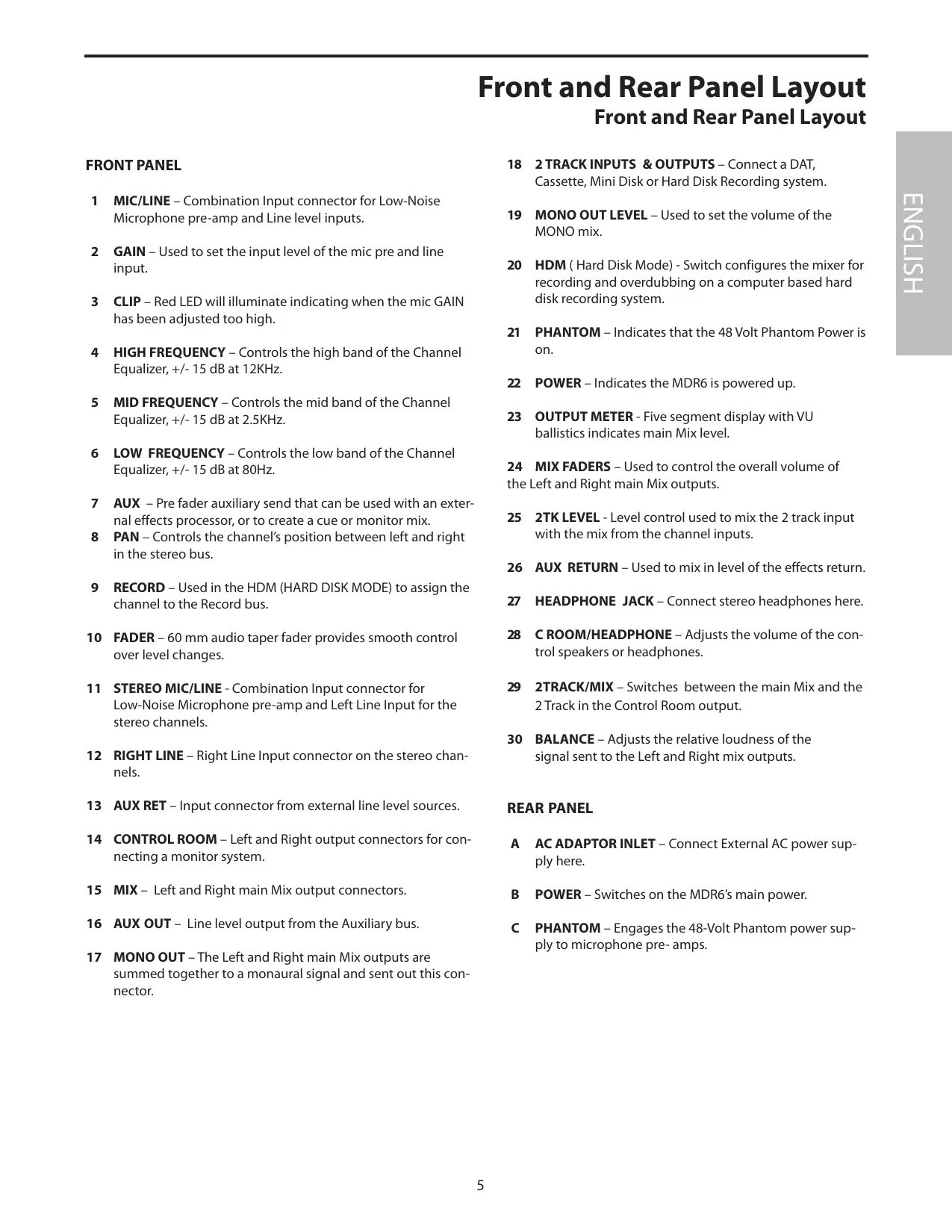
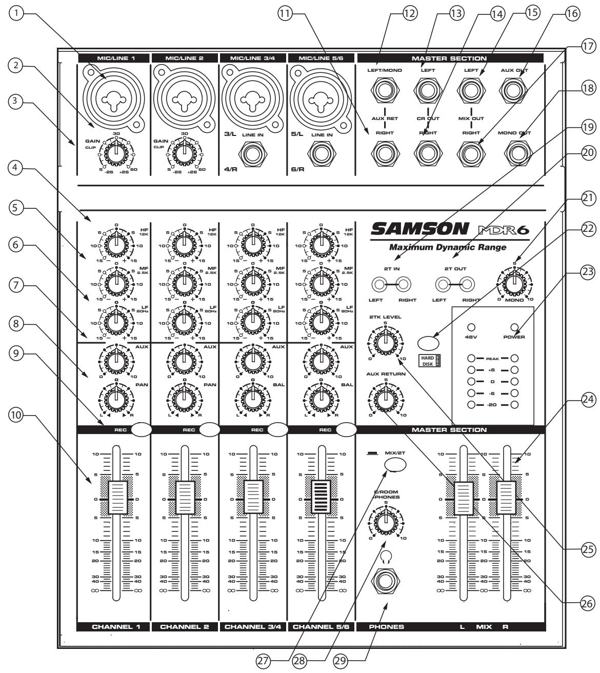
FRONT PANEL
1 MIC/LINE - Combination Input connector for Low-Noise Microphone pre-amp and Line level inputs.
2 GAIN - Used to set the input level of the mic pre and line input.
3 CLIP - Red LED will illuminate indicating when the mic GAIN has been adjusted too high.
4 HIGH FREQUENCY - Controls the high band of the Channel Equalizer, +/- 15 dB at 12KHz.
5 MID FREQUENCY - Controls the mid band of the Channel Equalizer, +/- 15 dB at 2.5KHz.
6 LOW FREQUENCY - Controls the low band of the Channel Equalizer, +/- 15 dB at 80Hz.
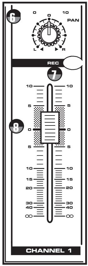
7 AUX - Pre fader auxiliary send that can be used with an external effects processor, or to create a cue or monitor mix.
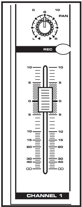
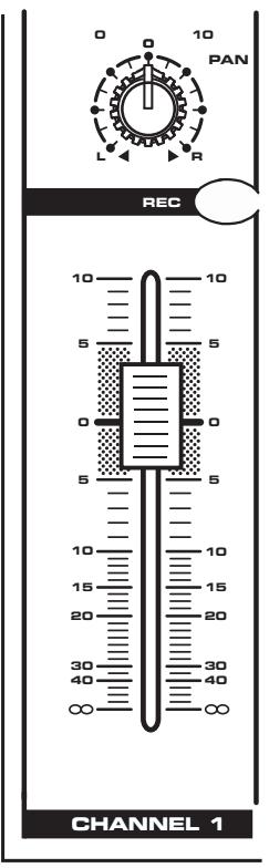
8 PAN - Controls the channel's position between left and right in the stereo bus.
9 RECORD - Used in the HDM (HARD DISK MODE) to assign the channel to the Record bus.
10 FADER - 60 mm audio taper fader provides smooth control over level changes.
11 STEREO MIC/LINE - Combination Input connector for Low-Noise Microphone pre-amp and Left Line Input for the stereo channels.
12 RIGHT LINE - Right Line Input connector on the stereo channels.
13 AUX RET - Input connector from external line level sources.
14 CONTROL ROOM - Left and Right output connectors for connecting a monitor system.
15 MIX - Left and Right main Mix output connectors.
16 AUX OUT - Line level output from the Auxiliary bus.
17 MONO OUT – The Left and Right main Mix outputs are summed together to a monaural signal and sent out this connector.
18 2 TRACK INPUTS & OUTPUTS - Connect a DAT, Cassette, Mini Disk or Hard Disk Recording system.
19 MONO OUT LEVEL – Used to set the volume of the MONO mix.
20 HDM ( Hard Disk Mode) - Switch configures the mixer for recording and overdubbing on a computer based hard disk recording system.
21 PHANTOM – Indicates that the 48 Volt Phantom Power is on.
22 POWER - Indicates the MDR6 is powered up.
23 OUTPUT METER - Five segment display with VU ballistics indicates main Mix level.
24 MIX FADERS - Used to control the overall volume of the Left and Right main Mix outputs.
25 2TK LEVEL - Level control used to mix the 2 track input with the mix from the channel inputs.
26 AUX RETURN - Used to mix in level of the effects return.
27 HEADPHONE JACK - Connect stereo headphones here.
28 C ROOM/HEADPHONE - Adjusts the volume of the control speakers or headphones.
29 2TRACK/MIX - Switches between the main Mix and the 2 Track in the Control Room output.
30 BALANCE - Adjusts the relative loudness of the signal sent to the Left and Right mix outputs.
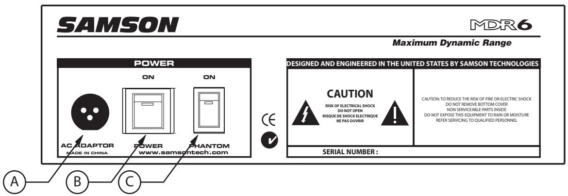
REAR PANEL
A AC ADAPTOR INLET - Connect External AC power supply here.
B POWER - Switches on the MDR6's main power.
C PHANTOM - Engages the 48-Volt Phantom power supply to microphone pre- amps.
Controls and Functions
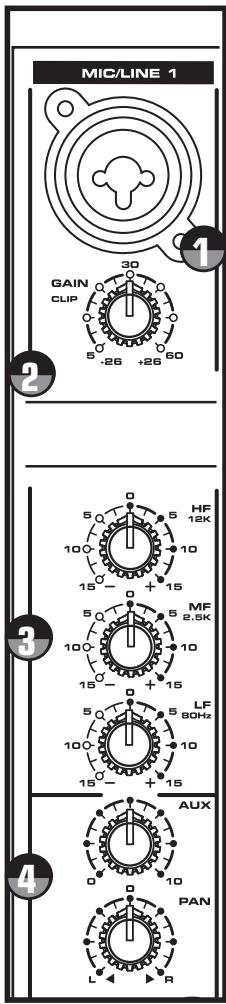
MONO INPUT CHANNEL SECTION
The following section details each part of the MDR6's MONO INPUT CHANNELS including the GAIN control, 3-BAND EQ, AUX send, RECORD, PAN and LEVEL controls. The input channels one through four on the MDR6 feature high quality, discrete transistor pre-amp providing transparency and extended dynamic range. The combination connector accepts a standard XLR mic cable for microphone level signals, or a standard 1/4'' phone cable, either balanced (TRS - TIP/ RING/SLEEVE) or unbalanced (TS - TIP/SLEEVE) for line level signals.

GAIN
The MDR6's pre-amp stage has a variable GAIN control with a range of 5 to 60dB on the MIC input and -26 to +26dB on the LINE input.

CLIP LED
The MDR6's MIC/LINE pre-amp also includes a CLIP LED which, when illuminated, indicates that the signal is peaking or overloading. To reduce distortion, lower the GAIN control to keep this LED from staying on.

CHANNEL EQUALIZER
The MDR6 input channels feature a 3-band equalizer allowing you to adjust the high, mid, and low frequencies independently on each channel. The channel's frequency response is flat when the knobs are in the "12:00" position. Rotating the knob towards the right will boost the corresponding frequency band by 15dB, and rotating it towards the left will cut the frequency by 15dB. The frequency centers, range of boost or cut, and equalizer type for each band are as follows:
High: 12KHz +/- 15dB shelving type
Mid: 2.5KHz +/- 15dB peaking type
Low: 80Hz + / - 15dB shelving type

AUX SEND
The AUX section is often used for a monitor mix in a live sound mixing, or for a headphone mix in a recording application. Each input channel includes an Aux send which controls the amount of that channel's signal that is sent to the Aux bus.

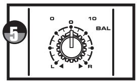
BALANCE (Stereo Inputs Only)
The MDR6's BALANCE control is used to place or position a mono input into the stereo main Left and Right MIX bus. For a stereo input, the balance control is used to center the sound between the Left and Right Mix bus. You can create a stereo image by panning some input signals to the left and others to the right.

PAN (Mono Inputs Only)
The MDR6's PAN control is used to place or position the mono signal into the stereo main Left and Right MIX bus. You can create a stereo image by panning some input signals to the left and others to the right. The MDR6's PAN control is a Power-Pan circuit, which includes a 3dB dip in the center position. This is desirable since there's a 3dB increase in gain when the mono input signal is heard in both the Left and Right MIX bus.

RECORD
The RECORD switch is used when operating the MDR6's HDM (HARD DISK MODE). If HDM in the master section is not engaged, the RECORD switch LED will be off and pressing the RECORD switch will have no effect. This is the normal mode of operation for most live mixing situations, however since the HDM provides some extra flexibility in signal routing. The HDM can be used for zone mixing as well. For more information on the HDM, see the section "Using the HDM" on page 14 of this manual.

FADER
The MDR6's 60mm input FADER controls the overall channel level. The input FADER features an audio taper and no detents for smooth fades.
Controls and Functions
MASTER SECTION
2 TRACK INPUT AND OUTPUT
The MDR6's 2 Track section provides the connections for playback and recording for an external device such as a DAT, cassette recorder, CD or Mini Disk. -The signal from a device connected to the 2T IN is heard only in the CONTROL ROOM and HEADPHONE outputs.

2TK LEVEL
The 2TK LEVELcontrol is used to adjust the amount of signal that is sent from the 2T IN jacks to the main L/R Mix bus. For more information see the following section "Mixing a 2-track with the Stereo MIX".

HDM
The HDM switch enables the HARD DISK MODE and is used to interface with a computer based, hard disk recorder. When turned on, the channel RECORD switches are activated for special bussing and monitoring features. For more information on using HDM, see the section "Using the HDM" on page 14 of this manual.
Mixing a 2-track with the Stereo Mix
You can mix the 2T IN with the input faders using the Hard Disk Mode. To do this follow these simple steps.
- Connect the 2-track device to the 2T IN input connectors and any mic or line inputs to channels 1-8.
In this mode the C/ROOM+PHONES control will act as your master volume, so for now, turn that all the way down. - Connect the CR LEFT and RIGHT outputs to your power amp or powered speakers.
- Press the HDM switch in the master section so that the yellow LED is illuminated.
Now raise the C/ROOM+PHONES level control up to a bit under 5. - Raise the MASTER FADERS to "O" so you can hear the mix from the input channels 1 - 8.
Now, raise the channel faders and 2TK LEVEL control until you have the mix you want.
Adjust the C/ROOM+PHONES level control to set the desired final level.
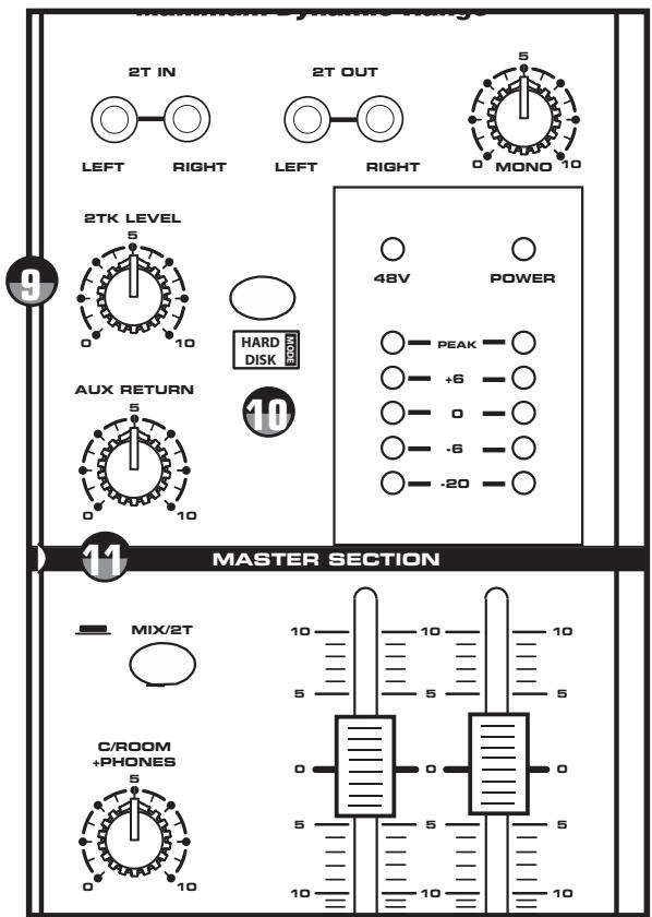
Auxiliary Return
The MDR6 has a stereo auxiliary return, which can be accessed via the pair of 1/4-inch phone jacks located on the top panel. The Auxiliary Return can be used to connect any stereo line level signal, but they are primarily used to connect the output of external effects processors.

AUX RET
This adjusts the amount of signal that is coming from the AUX RET jacks to the MAIN bus.

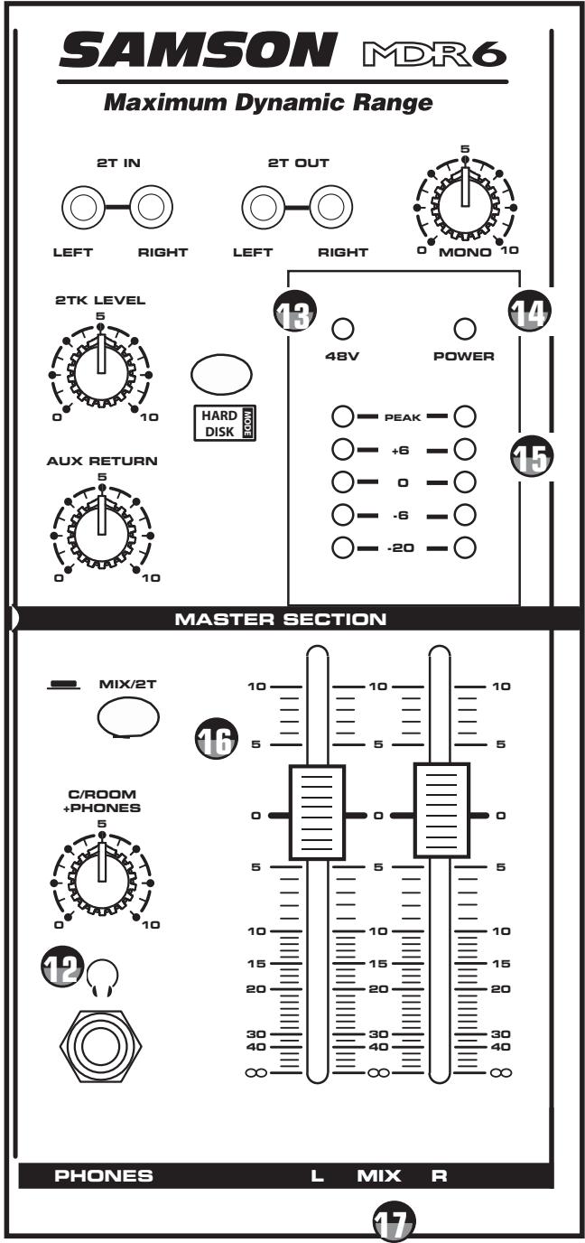
C/ROOM + PHONES
The C/ROOM + PHONES control is used to set the level sent to the control room outputs, and also to the headphone jack.

+48V - Phantom Power LED
The +48V LED illuminates indicating that the 48 volt phantom power is applied to the microphone pre-amps enabling use with condenser microphones.
The +48V LED will light up when the Phantom Power switch (located on the rear panel) is switched to the ON position.

POWER LED
The Power LED lights up to indicate that the main POWER switch (located on the rear panel) is on.

Output Level Meter
The OUTPUT LEVEL METER allows you to monitor the level of the signal which is being sent to the MIX OUT jacks.
NOTE: To avoid distortion, adjust the L/R faders so that the 0 indicator LED lights occasionally.

MIX/2T
The MIX/2T switch selects the signal source that you are monitoring in the CONTROL ROOM and HEADPHONE outputs. When the switch is in the up position, the signal source is from the LEFT/ RIGHT MIX bus. When the MIX/2T switch is in the down position, the signal source is from the 2-TRACK input.

LMIXR
The master MIX level controls are the overall volume control for the MIX bus. The MAIN level affects both the Control room signal which is output to the speakers and the line level signal which is output from the MIX OUT jacks.
MDR6 Input and Output Connections
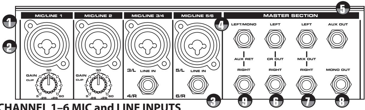
CHANNEL 1-6 MIC and LINE INPUTS
The MDR6's six input channels each have a "Combie" (combination XLR & 1/4-inch) connector with a LINE level, Hi-Z (High Impedance) input and a MIC level, Low-Z (Low Impedance) input. By using the GAIN control on channels 1+ 2 you can connect a variety of signal sources from microphones to line level devices such as synthesizers, and drum machines. All the LINE and MIC inputs are balanced. The MIC inputs are compatible with microphones with output impedances of 50 600 Ohms and the LINE inputs are compatible with line level devices of 600 Ohms.
NOTE: It is not possible to simultaneously use both the LINE and MIC inputs on the same channel (with the exception on the stereo input channels). Use only one of the inputs for the appropriate source on each channel. Following below is a detailed description of the MDR6's input and output connectors.

Line Level Input - Mono Input Channels
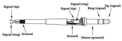
Use these inputs to connect synthesizers, drum machines, effects processors or any line-level signal. The LINE inputs have a nominal operating level of -40dB through - 10dB. TRS phone jacks (located in the center of the Combination connector). Connector pin-out - Sleeve: Ground, Tip: Hot (+), Ring: Cold (-)

Microphone Input - Mono Input Channels
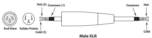
Use these inputs to connect Low Impedance microphones and low level signals from direct boxes. The MIC inputs have a nominal operating level of -50dB through -20dB . The MIC inputs also feature +48V phantom power, allowing you to use condenser microphones. The Phantom Power switch located on the MDR6's rear panel enables phantom power on all the microphone inputs when set to the ON position. XLR Connector pin-out - Pin 1: Ground, Pin 2: Hot (+), Pin 3: Cold (-)

Line Level Input - Stereo Input Channels
The MDR6's stereo channels have a stereo LINE input with the Left Input located in the center of the Zombie connector and a separate 1/4-inch connector for the Right Input. You can connect the outputs from stereo devices such as synthesizers, drum machines, effects processors or any stereo line-level signal. The LINE inputs have a nominal operating level of -40dB through - 10dB. TRS phone jacks Connector pin-out - Sleeve: Ground, Tip: Hot (+), Ring: Cold (-)

Microphone Input - Stereo Input Channels
The MDR6's stereo channels have a utility MIC input located on the Zombie connector. The utility MIC inputs have a nominal operating level of -50dB through -20dB . The MIC inputs also feature +48V phantom power, allowing you to use condenser microphones. The Phantom Power switch located on the MDR6's rear panel enables phantom power on all the microphone inputs when set to the ON position. XLR Connector pin-out - Pin 1: Ground, Pin 2: Hot (+), Pin 3: Cold (-)
MDR6 Input and Output Connections
EXTERNAL OUTPUT JACKS
The MDR6 features several output connectors allowing you to interface a variety of external devices. A stereo recording device such as a cassette recorder can be connected to the 2 Track jacks, and additional power amplifiers can be connected to the CONTROL ROOM and MAIN output jacks.

AUX Output
The signal present at the AUX output is sent from the AUX bus, which is fed from the AUX send on the input channels. The AUX output can be used as the MONITOR MIX bus in a live sound situation by connecting the output to a power amp and monitor speaker.

The Control Room outputs are used to connect a studio monitor system. The Control Room outputs have the same output as the L/R MIX, however, the level can be adjusted independently from the main mix using the C ROOM/HEADPHONES control.

LEFT/RIGHT MIX
In a live sound application the LEFT/ RIGHT MIX outputs are connected to a power amplifier or powered speakers. In a recording application, the LEFT/ RIGHT MIX outputs are used to connect a stereo device such as computer sound card, DAT, or cassette recorder.

MONO OUTPUT
The Left and Right Mix outputs are summed together and sent to the MONO output. The level of the Mono signal can be adjusted using the MONO OUT level control located just below the connector and used to feed a speaker zone in a fixed installation.

AUX RETURN LEFT/RIGHT
The AUX RETURN LEFT/RIGHT are stereo inputs that are generally used to connect the outputs of an effects processor, but can also accept the signal from any line level source like a keyboard, recorder and even another mixer. The signal connected to he AUX RETURN LEFT/RIGHT will feed the main LEFT/RIGHT MIX bus. The overall level is controlled by the AUX RET knob located in the master section on the front panel.
Operating the MDR6
SENDING AN INDEPENDENT MIX TO THE MONITOR SPEAKERS
The MDR6's AUX send can be used to feed a separate set of amplifiers and loudspeakers for stage monitors. This lets you build one stereo mix for the amplifiers and speakers facing the audience and the other mono mix for the amplifiers and monitor speakers facing the musicians.
- Raise the AUX controls for the channels that you wish to hear from the monitor speakers.
NOTE: The AUX controls are "PRE-FADER SENDS" which means they are not affected by the FADER level settings of each channel. This allows you to create a mix for the monitors that is independent of the main LEFT and RIGHT MIX.

- In order to get the most gain from your monitor mix, use an external graphic equalizer like a Samson S curve 131 to cut out any frequencies that cause feedback.
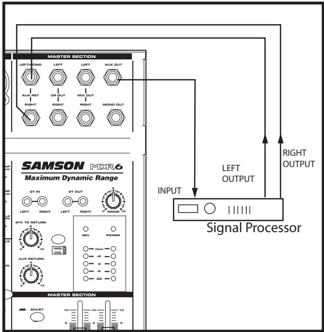
USING AN EXTERNAL EFFECT
If you want to use an external device for effects processing, you can easily connect the unit using the MDR6 AUX bus. Follow the simple steps below to interface your processor:
- Set the L/R mix faders to the "0" position.
- Raise the AUX RETURN knobs for the channels to which you want the external effect to be applied.
- Set the input level of the external effect so that the sound is not distorted and so that the effect's input meter does not indicate a clipped signal.
- Use the AUX control to adjust the level of the effects processed by the external effects device.
The MDR6 has a dedicated input for playing back a CD, Tape or Mini Disk, which is heard in the Control Room and Headphone
outputs. Below is a description of how you can play back a CD, Tape or MD using the MDR6's 2 TRACK INPUT.
- Turn the CONTROL ROOM level control all the way down.
Adjust the2TK LEVEL control a bit below the "O" position.
Start playback on the CD, Tape or MD player.
Now raise the CONTROL ROOM level until you reach a comfortable listening level.
For more information see the section "Mixing a 2-track with the Stereo MIX" on page 8 in this manual.
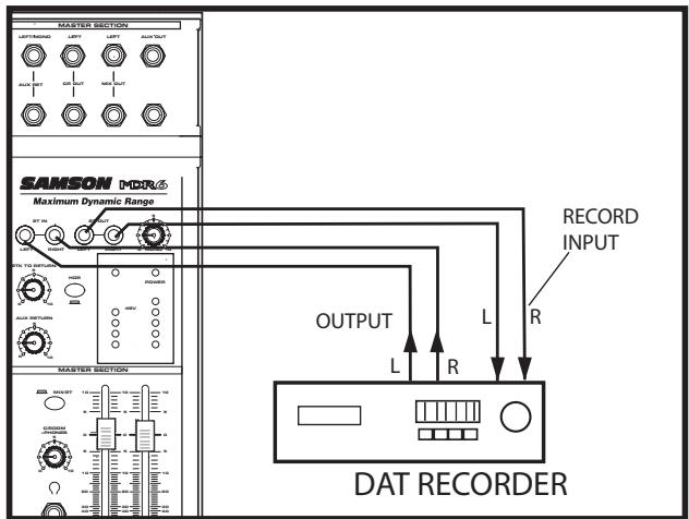
You can record the audio from the MDR6's mixer section including the MIC, LINE, TAPE IN and AUX inputs to a Cassette deck, MD, DAT or any other type of recorder using the 2 Track outputs. Simply connect the MDR6's 2-Track OUT to the input jacks of the recorder as shown in the diagram to the right.
Operating the MDR6
BASIC OPERATION
The following section explains the basic operation of the MDR6.
CONNECTING MICROPHONES AND INSTRUMENTS
- Before connecting mics or instruments, make sure that the power of all your systems components including the MDR6 is turned off. Also, make sure that the Left and Right MIX faders are turned all the way down.
- Connect the cables to your microphones and instruments, and insert the other end of the cable firmly into the appropriate input on the MDR6.
NOTE: SETTING THE INPUT GAIN - When connecting a microphone to channels 1 + 2 , it's a good idea to start with the Gain Control turned all the way down. Set the input fader to the "0" position and slowly raise the GAIN control until you see the CLIP LED turn on. Now, back the GAIN control down so that the CLIP LED only lights for a short time during the loudest input the channel will see.
- Switch on the power of any peripheral devices, and then power up the MDR6.
NOTE: It is important to remember the Golden
Rule of audio ... "LAST ON, FIRST OFF".
Translated, this means that when turning on
your system, you should always turn your power
amplifiers or powered monitors on LAST, and when turning your system off, turn your power amps off FIRST. This helps avoid any loud pops caused by inrush current at power up, which can sometimes damage loudspeakers.
- Turn on your power amp or powered monitors and raise the level control to the manufacturers' recommended operating level.
- Set the Left and Right MIX faders in the MDR6's master section to the "0" position.
- While speaking into the mic (or playing the instrument), adjust the channel Fader control so that the "0" LED of the MAIN section peak level meter lights occasionally.
- You can shape the tone of each channel by adjusting the equalizer controls as desired.
Operating the MDR6
Using The HDM (HARD DISK MODE)
The MDR6 includes an exclusive HDM (HARD DISK MODE) that has been designed to interface with computer based hard disk recorders. Never before have such flexible routing and monitoring been included in such a small mixer. The HDM provides a seamless solution for recording and overdubbing on a hard disk recorder by providing a special record bus plus unique monitoring to solve latency problems.
When you are working with the mixer configured to HDM, the MDR6 engages the RECORD bus and a special 2-Track listening mode. When engaged, the HDM allows you to assign any of the channels to the RECORD bus. In this mode, the 2-Track output (located in the Master section) is now outputting the mix from the RECORD bus. While in HDM you can still mix in the 2-Track return, however, it will not be recorded since it is not sent to the RECORD (2-Track Out) bus. Therefore, if your hard disk recorder is connected to the 2-Track Inputs and Outputs, you can listen to the output of the hard disk recorder while listening to the MDR6 input channels. By listening to the tracks that you are recording directly from the
input faders, you avoid having to loop back the track you are recording, thereby eliminating latency delays. Follow the examples below to use the HDM.
Set the MDR6 INPUT faders all the way down and the L & R MIX faders to the "0" position. For this example, we'll first record a rhythm track sequence from a MIDI keyboard (any stereo track will do), then do an overdub. If you are using an imported loop or internal sequencer, skip the Recording section and go on to the Overdub section.
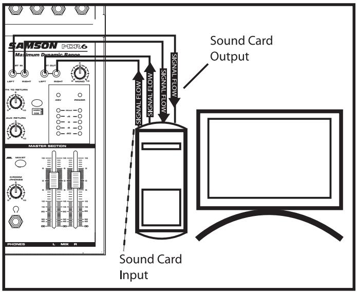
Recording Using HDM
- Connect the output from your computer sound card to the MDR6's 2-Track In and then connect the MDR6's 2-Track Output to the input of the sound card.
- Connect the outputs from a MIDI keyboard to the stereo inputs channels 5/6.
- Engage the HDM switch in the MASTER section.
- Press the RECORD switch on the MDR6's channel 5/6. The input channel's REC LED will flash indicating the channel is assigned to the RECORD bus.
- Raise the channel 5/6 fader to the nominal area (0).
- Now, test your listening level by starting the MIDI sequencer and slowly raising the Control Room output level until you have set a comfortable listening level. If the sound is too low, raise the output level of your keyboard. If the sound is distorted, lower the output level of your keyboard.
- Select the record enable on the tracks you are recording to on your hard disk recorder and set a level as described in your software manual.
- Press REC/PLAY on your recorder and play on the MIDI sequencer.
Using The HDM (Continued)
Over dubbing Using HDM
Now that you have recorded a basic rhythm track you can overdub additional tracks using MDR6's HDM. For this example, we'll overdub a vocal track using a microphone. Follow the steps below.
- Connect the output from your computer sound card to the MDR6's 2-Track In and then connect the MDR6's 2-Track Output to the input of the sound card.
- Connect a microphone to the MDR6's Channel 1 microphone input and set a proper level using the GAIN control and peak LED.
- Engage the HDM switch.
- Press the RECORD switch on the MDR6's Channel 1. The input channel's REC LED will flash indicating the channel is assigned to the RECORD bus.
- Raise the Channel 1 fader to the nominal area (0).
- Now, test your listening level by pressing PLAY on your hard disk recorder and by slowly raising the 2TK LEVEL level control until you have set a comfortable listening level. Use the 2TK LEVEL and CONTROL ROOM/HEADPHONE level controls to set a good balance between the hard disk recorder and the input.
- Select the record enable on the track you are recording to on your hard disk recorder and set a level as described in your software manual.
- Press REC/PLAY on your hard disk recorder and record your vocal track.
NOTE: The RECORD bus is stereo, therefore the input channels PAN and BALANCE controls will determine how much signal is sent to the LEFT or RIGHT
2-TRACK output. If you want an input channels signal to send only to the LEFT RECORD bus, then set the PAN control all the way to the left. If you want an input channels signal to send only to the RIGHT RECORD bus, then set the PAN control all the way to the right.
MDR6 System Set-Ups
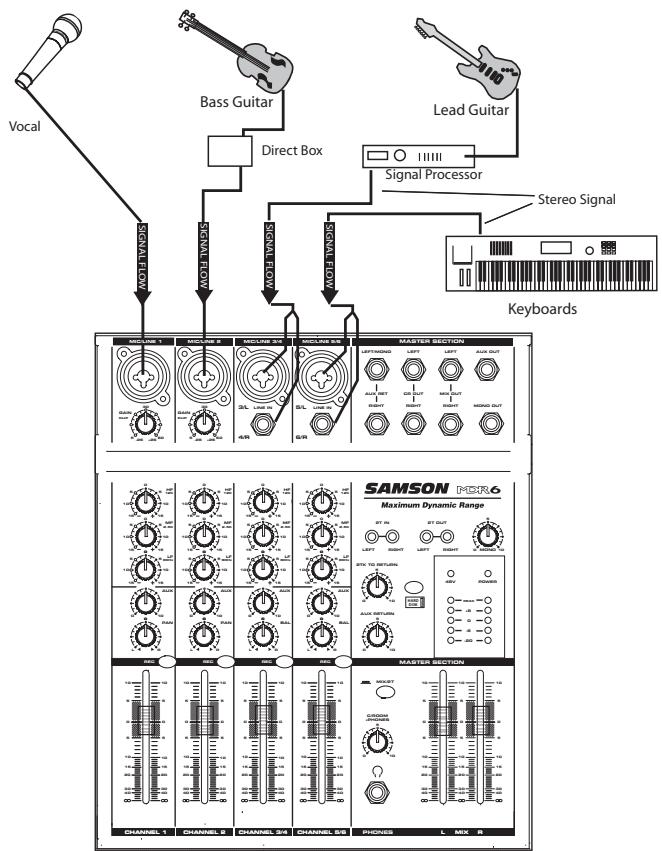
MDR6 LIVE SOUND SET-UP
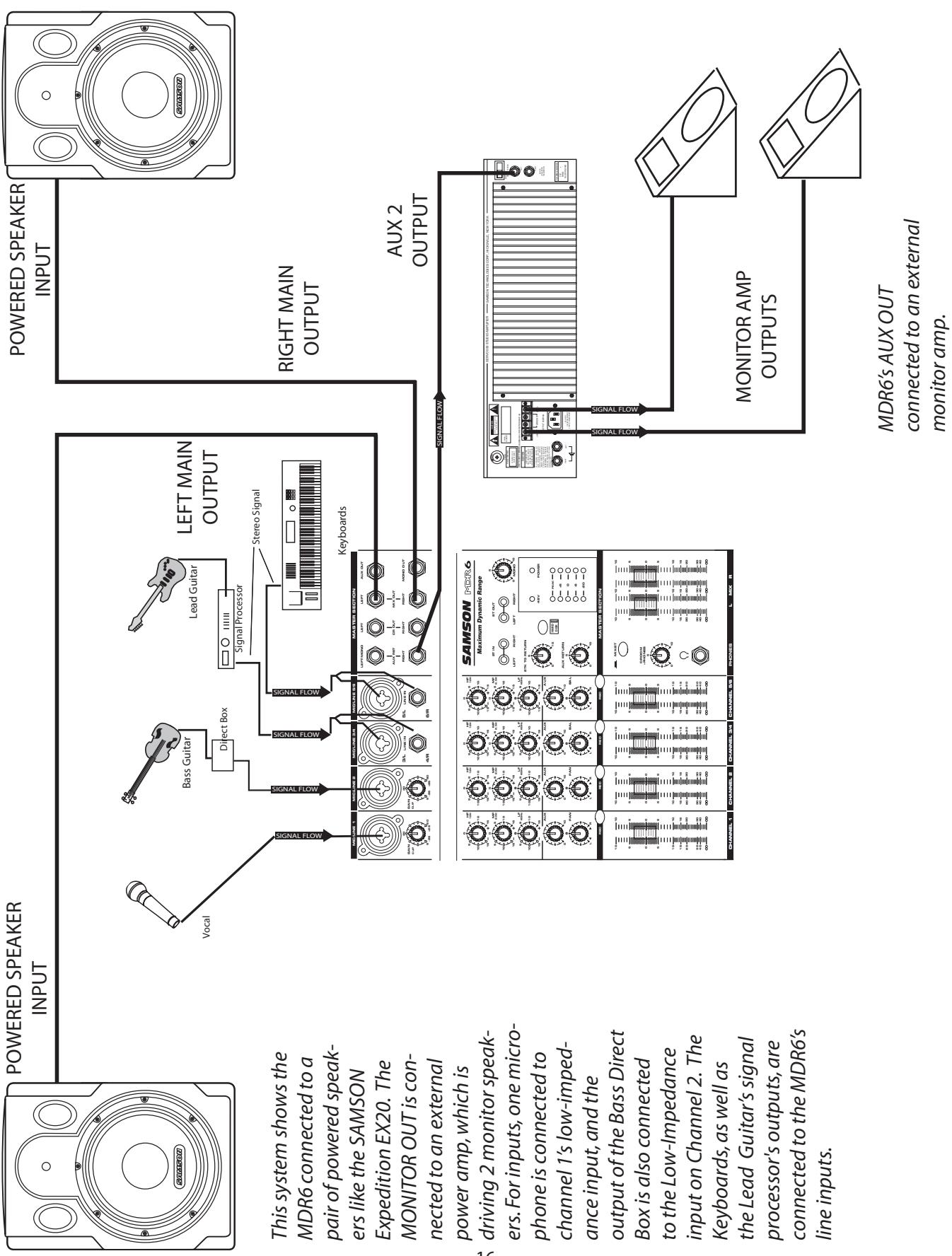
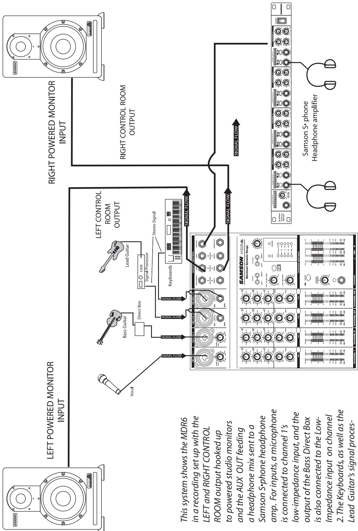
the MDR6s line inputs.
sor's outputs, are connected to
Lead Guitar's signal process
2. The Keyboards, as well as the
Impedance input on channel
is also connected to the Low
output of the Bass Direct Box
low-impedance input and the
is connected to channel 1's
amp. For inputs, a microphone
Samson S·phone headphone
a headache mix sent to a
and the AUX OUT feeding
to powered studio monitors
ROOM output hooked up
LEFT and RIGHT CONTROL
in a recording set up with the
This system shows the MDR6
IN
RIGHT POWERED MONITOR
INPUT
LEFT POWERED MONITOR
Introduction
High: 12 kHz, +/- 15 dB, Shelving-EQ
Mid: 2.5 kHz, +/- 15 dB, Peak-EQ
Low: 80Hz, + / - 15 dB Shelving-EQ

AUX SEND
The are several ways to interface the MDR6 to support a variety of applications. The MDR8 features balanced inputs and outputs, so connecting balanced and unbalanced signals is possible.
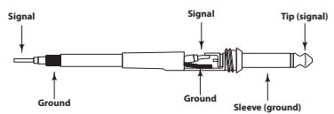
Unbalanced 1/4'' Connector
Balanced TRS 1/4" Connector
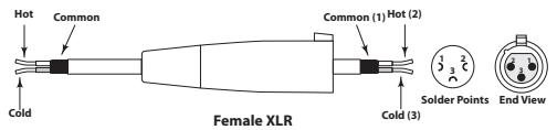
XLR Balanced Wiring Guide
CONNEXIONS DE LA CONSOLE MDR6
| Frequency Response (Trim @ Min, unity gain ± 3 dB) | |
| Mic to Main | 5 Hz - 54 kHz |
| Line to Main | 5 Hz - 54 kHz |
| Aux Return to Main | 5 Hz - 98 kHz |
| Line to Aux Send | 5 Hz - 57 kHz |
| T.H.D. (Trim @ Min, +4dBu output, unity gain, 1 kHz w/30 kHz LPF) | |
| Mic/Line to Main (Mono Ch) | 0.0% |
| Line to Main (Stereo Ch) | 0.02% |
| Line to Aux Send | 0.02% |
| Equivalent Input Noise ("A" filter on, input shorted) | |
| Mic | -128 dB |
| Line | -104 dB |
| Maximum Voltage Gain | |
| Mic to Main | 74 dB |
| Line to Main (Mono Ch) | 56 dB |
| Line/Tape to Main (Stereo Ch) | 34 dB |
| Aux Return to Main | 20 dB |
| Mic to Aux Send | 74 dB |
| Line to Aux Send (Stereo Ch) | 34 dB |
| Residual Noise (30 kHz LPF, all control Min) | |
| Main | -89 dBu |
| Aux Send | -86 dBu |
| Crosstalk (@ 1 kHz w/ 30 kHz LPF) | |
| Ch vs. Ch | 75 dB |
| Input vs. Output | 87.5 dB |
| Peak LED Sensitivity (before clipping) | 5 dB |
| CLIP Indicators | Turn on: THD> 0.1% |
| Headphone output (600 ohm load) | 100 mW |
| Maximum Input Level (1 kHz, ± 3dB) | |
| Mic Input (Mono"Ch) | 10.5 dBu |
| Line Input (Stereo Ch) | 7.6 dBu |
| Input Channel Equalizer (± 2dB) | |
| High (shelving) | 12 kHz ±15 dB |
| Mid (peaking) | 2.5 kHz ± 15 dB |
| Low (shelving) | 80 Hz ±15 dB |
| Meters | 6 POINT LED METERS (-20, -12, -6, 0, +6dB and PEAK) |
| Phantom Power | +48V |
| Power Requirement | 110V-240V, 50/60Hz |
| Power Consumption | 19 watts |
| Dimensions (W x D x H) | 9" x 10 3/4" x 3 1/2" (229mm) x (273 mm) x (89mm) |
| Weight | 4.5 lbs. (2.1 kg) |
Frequenzgang (Trim @ Min, Unity Gain ± 3 dB)
| Mic zu Main | 5 Hz - 54 kHz |
| Line zu Main | 5 Hz - 54 kHz |
| Aux Return zu Main | 5 Hz - 98 kHz |
| Line zu Aux Send | 5 Hz - 57 kHz |
Klirrfaktor (Trim @ Min, +4 dBu Ausgang, Unity Gain, 1 kHz mit/30 kHz LPF)
| Mic/Line zu Main (Mono-Kanal) | 0.02 % |
| Line zu Main (Stereo-Kanal) | 0.02 % |
| Line zu Aux Send | 0.02 % |
| Mic | -128 dB |
| Line | -104 dB |
| Hng (600 Ohm Last) | 100 mW |
Max.Eingangspegel (1kHz,± 3dB)
| High (shelving) | 12 kHz ±15 dB |
| Mid (peaking) | 2.5 kHz ± 15 dB |
| Low (shelving) | 80 Hz ±15 dB |
Gewicht
- Maximum Dynamic Range
- WARNING
- AVIS
- CAUTION
- ATTENTION
- Important Safety Instructions
- Controls and Functions
- Inhalt
- Introduction
- Front and Rear Panel Layout
- Front and Rear Panel Layout Front and Rear Panel Layout
- FRONT PANEL
- REAR PANEL
- MONO INPUT CHANNEL SECTION
- GAIN
- CLIP LED
- CHANNEL EQUALIZER
- AUX SEND
- BALANCE (Stereo Inputs Only)
- PAN (Mono Inputs Only)
- RECORD
- FADER
- MASTER SECTION
- TRACK INPUT AND OUTPUT
- 2TK LEVEL
- HDM
- Mixing a 2-track with the Stereo Mix
- Auxiliary Return
- AUX RET
- C/ROOM + PHONES
- +48V - Phantom Power LED
- POWER LED
- Output Level Meter
- MIX/2T
- LMIXR
- MDR6 Input and Output Connections
- CHANNEL 1-6 MIC and LINE INPUTS
- Line Level Input - Mono Input Channels
- Microphone Input - Mono Input Channels
- Line Level Input - Stereo Input Channels
- Microphone Input - Stereo Input Channels
- EXTERNAL OUTPUT JACKS
- AUX Output
- LEFT/RIGHT MIX
- MONO OUTPUT
- AUX RETURN LEFT/RIGHT
- Operating the MDR6
- SENDING AN INDEPENDENT MIX TO THE MONITOR SPEAKERS
- USING AN EXTERNAL EFFECT
- BASIC OPERATION
- CONNECTING MICROPHONES AND INSTRUMENTS
- Using The HDM (HARD DISK MODE)
- Recording Using HDM
- Using The HDM (Continued)
- Over dubbing Using HDM
- MDR6 System Set-Ups
- MDR6 LIVE SOUND SET-UP
- CONNEXIONS DE LA CONSOLE MDR6
Brand : SAMSON
Model : MDR6
Category : Audio Mixer