
LD-POWER 120 - Power Supply JBSYSTEMS LIGHT - Free user manual and instructions
Find the device manual for free LD-POWER 120 JBSYSTEMS LIGHT in PDF.

| Product type | Power supply for LED projectors |
| Brand | JBSYSTEMS LIGHT |
| Model | LD-POWER 120 |
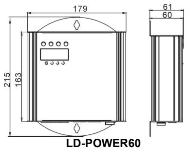
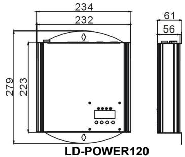
| Dimensions | Refer to the diagram in the manual |
| Weight | 2.1 kg |
| Mains power | 100-240 V AC, 50/60 Hz |
| Total output power | 120 W (2 zones of 60 W) |
| Number of LED zones | 2 independent zones |
| Max. LED load per zone (RGB/RGBW) | 12 LEDs per color (max. 48 LEDs) |
| Max. LED load per zone (white mode) | 4 circuits, max. 12 LEDs per circuit (total 48 LEDs) |
| LED output connectors | RJ45 (CAT5e), wiring 1:1 |
| Max. LED cable length | 80 meters per zone |
| DMX connectors | XLR 3-pin male (input) / female (output) |
| Number of DMX channels | 2 to 11 channels depending on mode |
| DMX modes | 7 modes (RGBW, RGB, white, etc.) |
| Standalone modes | 19 preprogrammed shows (including 3 editable) |
| Functions | Master/Slave, white balance adjustment, manual mode, black out, LED display |
| Fuse | 250 V 2A, slow-blow, 20 mm glass |
| Operating temperature | 45°C max |
| Usage | Indoor only |
| Maintenance | Clean with a slightly damp soft cloth, avoid solvents |
| Safety | Class I, mandatory grounding, do not open |
Frequently Asked Questions - LD-POWER 120 JBSYSTEMS LIGHT
User questions about LD-POWER 120 JBSYSTEMS LIGHT
0 question about this device. Answer the ones you know or ask your own.
Ask a new question about this device
Download the instructions for your Power Supply in PDF format for free! Find your manual LD-POWER 120 - JBSYSTEMS LIGHT and take your electronic device back in hand. On this page are published all the documents necessary for the use of your device. LD-POWER 120 by JBSYSTEMS LIGHT.
USER MANUAL LD-POWER 120 JBSYSTEMS LIGHT
Copyright © 2009 by BEGLEC comm.v.a.
t Hofveld 2 ~ B1702 Groot-Bijgaarden ~ Belgium
Reproduction or publication of the content in any manner, without express permission of the publisher, is prohibited.
CE
Version: 1.0

ARCHITECTURAL


EN - DISPOSAL OF THE DEVICE
Dispose of the unit and used batteries in an environment friendly manner according to your country regulations.
FR-DECLASSES L'APPAREIL
Thank you for buying this BRITEQ® product from our Light Designer Series. To take full advantage of all possibilities, please read these operating instructions very carefully.
FEATURES
This unit is radio-interference suppressed. This product meets the requirements of the current European and national guidelines. Conformity has been established and the relevant statements and documents have been deposited by the manufacturer.
- Reliable LED power supply, specially designed for use with our passive high power LED projectors!
- Can be used with both RGB and RGB+WHITE projectors
- 7 different DMX-modes for maximum flexibility
- Can be used in standalone mode
16 internal chases
- 3 user editable chases, each containing max. 42scenes
- master/slave connection
- manual mode
- White balance setup
Each output zone supports up to 12 LEDs per color - Easy navigation thanks to LED display.
BEFORE USE
Check the contents:
Check that the carton contains the following items:
- LD-POWER60 or LD-POWER120 unit
- User manual
Some important instructions:
- Before you start using this unit, please check if there's no transportation damage. Should there be any, do not use the device and consult your dealer first.
- Important: This device left our factory in perfect condition and well packaged. It is absolutely necessary for the user to strictly follow the safety instructions and warnings in this user manual. Any damage caused by mishandling is not subject to warranty. The dealer will not accept responsibility for any resulting defects or problems caused by disregarding this user manual.
- Keep this booklet in a safe place for future consultation. If you sell the fixture, be sure to add this user manual.
- To protect the environment, please try to recycle the packing material as much as possible.
SAFETY INSTRUCTIONS:

CAUTION
RISK OF ELECTRIC SHOCK DO NOT OPEN

CAUTION: To reduce the risk of electric shock, do not remove the top cover. No user-serviceable parts inside. Refer servicing to qualified service personnel only.

The lightning flash with arrowhead symbol within the equilateral triangle is intended to alert the use or the presence of un-insulated "dangerous voltage" within the product's enclosure that may be of sufficient magnitude to constitute a risk of electric shock.

The exclamation point within the equilateral triangle is intended to alert the user to the presence of important operation and maintenance (servicing) instructions in the literature accompanying this appliance.

This symbol means: indoor use only

This symbol means: Read instructions
This symbol means: Safety Class I appliance

The device is suitable for mounting on standard flammable surfaces. Standard flammable surfaces include building materials such as wood and wood-based materials more than 2mm thick.
- To prevent fire or shock hazard, do not expose this appliance to rain or moisture.
- To avoid condensation to be formed inside, allow the unit to adapt to the surrounding temperatures when bringing it into a warm room after transport. Condense sometimes prevents the unit from working at full performance or may even cause damages.
- This unit is for indoor use only.
- Don't place metal objects or spill liquid inside the unit. No objects filled with liquids, such as vases, shall be placed on this appliance. Electric shock or malfunction may result. If a foreign object enters the unit, immediately disconnect the mains power.
- No naked flame sources, such as lighted candles, should be placed on the appliance.
- Don't cover any ventilation openings as this may result in overheating.
- Prevent use in dusty environments and clean the unit regularly.
- Keep the unit away from children.
- Inexperienced persons should not operate this device.
Maximum save ambient temperature is 40^ . Don't use this unit at higher ambient temperatures. - Always unplug the unit when it is not used for a longer time or before you start servicing.
- The electrical installation should be carried out by qualified personal only, according to the regulations for electrical and mechanical safety in your country.
- Check that the available voltage is not higher than the one stated on the rear panel of the unit.
- The socket inlet shall remain operable for disconnection from the mains.
- The power cord should always be in perfect condition: switch the unit immediately off when the power cord is squashed or damaged. It must be replaced by the manufacturer, its service agent or similarly qualified persons in order to avoid a hazard
- Never let the power-cord come into contact with other cables!
- This appliance must be earthed to in order comply with safety regulations.
- In order to prevent electric shock, do not open the cover. Apart from the mains fuse there are no user serviceable parts inside.
- Never repair a fuse or bypass the fuse holder. Always replace a damaged fuse with a fuse of the same type and electrical specifications!
- In the event of serious operating problems, stop using the appliance and contact your dealer immediately
- Please use the original packing when the device is to be transported.
- Due to safety reasons it is prohibited to make unauthorized modifications to the unit.
MAINTENANCE
Clean by wiping with a polished cloth slightly dipped with water. Avoid getting water inside the unit. Do not use volatile liquids such as benzene or thinner which will damage the unit.
FUNCTIONS (REAR)
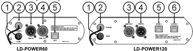
- FUSE HOLDER: Never repair a fuse or bypass the fuse holder. Always replace a damaged fuse with a fuse of the same type and electrical specifications!
-
MAINS CABLE: can be connected to mains outlet sockets ranging from 100Vac to 240Vac 50/60Hz.
-
DMX input: 3pin male XLR-connector used to connect universal DMX-cables. This input receives instructions from any DMX-controller.
- DMX output: 3pin female XLR-connector used to connect the LD-POWER with the next unit in the DMX chain or with another LD-POWER60/120.
-
LED ZONE1: output to the LED fixtures. Please note that only LED fixtures of our LD-series can be connected properly! LD-Power60 has only 1 LED-zone output, LD-Power120 has 2 independent LED-zone outputs. Each zone supports a maximum load as explained below:
-
RGB-MODE (Mode3 + 4): 12 LEDs maximum for each color (12R + 12G + 12B)
- RGBW-MODE (Mode1 + 2): 12 LEDs maximum for each color (12R + 12G + 12B + 12W)
-
WHITE MODE (Mode5 + 6 +7): 4 circuits, each supporting max. 12 LEDs (total max. 48pcs)
-
LED ZONE2: only available on LD-POWER120, can be controlled complete independent from zone1.
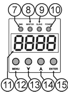
FUNCTIONS (FRONT)
- DMX LED: is lit when a DMX signal is detected on the input.
- MASTER LED: is lit when no cable is connected to the DMX-input, the unit works in master mode and shows the last selected internal show. (see later)
- SLAVE LED: is lit when the DMX input is connected to another LD-POWER60/120 that works in master mode.
- POWER LED: is lit when the mains cable is inserted and the unit is working.
- DISPLAY: 4-digit display, gives information on the selected functions.
- MENU BUTTON: press this button shortly to access the setup menu. Press this button for about 2 seconds to leave the setup menu and save the selected options.
- DOWN BUTTON: press this button to go to the previous item in the setup menu or lower the value shown on the display.
- UP BUTTON: press this button to go to the next item in the setup menu or increase the value shown on the display.
- ENTER BUTTON: press this button to confirm your selection in the setup menu.
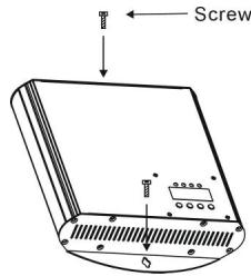
INSTALLATION + ADDRESSING
Important: The installation should be carried out by qualified personal only, according to the regulations for electrical and mechanical safety in your country.
The LD-POWER60/120 should be fixed on a non-flammable flat surface. For example you can fix the unit against a wall using two adapted screws. The orientation is not important but make sure that enough ventilation is available.
IVERY IMPORTANT - READ IT BEFORE YOU CALL FOR HELP!
- Make sure the unit is not connected to the mains during installation and wiring!
- The LD-Power power supplies are intended only for use with passive LED projectors from our LD-series.
- Make sure the maximum load per LED output zone is not exceeded!
- The maximum cable length between the LD-POWER output and all connected projectors is 80 meters!
- At the end of each line (zone) NO RJ45 connector can be left open, you MUST use a terminator (LD-TERM RJ-45) otherwise: NO light!
- RGB and RGBW projectors can NOT be mixed in the same line (zone).
- 2 different LED projectors exist: TYPE1 needs a splitter box to be connected, TYPE2 not!
Electrical installation LED projector outputs:
The passive LED projectors from our LD-series use CAT5e cables and RJ45 connectors to connect them to the LD-POWER power supplies. You can use our standard cables ("LD-PATCH RJ45", available in different lengths) but you can also make your own cables with CAT5e cable and RJ45 connectors you can buy from
any computer shop. However we like to warn you that making your own cables is not easy and requires special tools and some experience! The cables should be wired
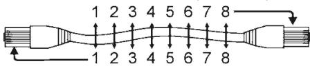
1:1 (pins with same numbers connected together). The maximum distance between the LD-Power and the LED-projectors is 80meters.
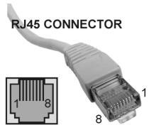
Wiring of the RJ45 connectors
Pin1: Red LED +
Pin2:GreenLED+
Pin3: Blue LED +
Pin4: White LED +
Pin5: Red LED -
Pin6:GreenLED-
Pin7: Blue LED -
Pin8:WhiteLED-
ENCLOSURE CABLE
IMPORTANT: not all LED-projectors are connected the same way, two different types are used:
TYPE 1: these LED-projectors always have a small cable with RJ45 connector attached. For example: LD-AQUA, LD-BAR, LD-UPLIGHT, ...
If you connect more than one projector to the LD-POWER, you should always use a splitter! Two different splitters are available:
LD-SPLIT RJ45: used for normal indoor applications (ex. LD-BAR)
LD-SPLIT IP68: used for waterproof outdoor applications (ex. LD-AQUA, LD-UPLIGHT)
TYPE 2: these LED-projectors always have two female RJ45 connectors (in/out). For example: LD-BRICK, LD-DOWNLIGHT, ...
You can simply daisychain these projectors with standard patch cables.
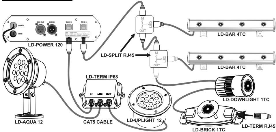
Example of an installation
Electrical installation DMX-inputs:
- The DMX-protocol is a widely used high speed signal to control intelligent light equipment. You need to "daisy chain" your DMX controller and all the connected units with a good quality balanced cable.
- Both XLR-3pin and XLR-5pin connectors are used, however XLR-3pin is more popular because these cables are compatible with balanced audio cables.
Pin layout XLR-3pin: Pin1 = GND ~ Pin2 = Negative signal (-) ~ Pin3 = Positive signal (+) - Pin layout XLR-5pin: Pin1 = GND ~ Pin2 = Negative signal (-) ~ Pin3 = Positive signal (+) ~ Pins4+5 not used.
- To prevent strange behavior of the light effects, due to interferences, you must use a 90 to 120 terminator at the end of the chain. Never use Y-splitter cables, this simply won't work!
- Make sure that all units are connected to the mains.
- Each unit in the chain needs to have its proper starting address so it knows which commands from the controller it has to decode. In the next section you will learn how to set the DMX addresses.
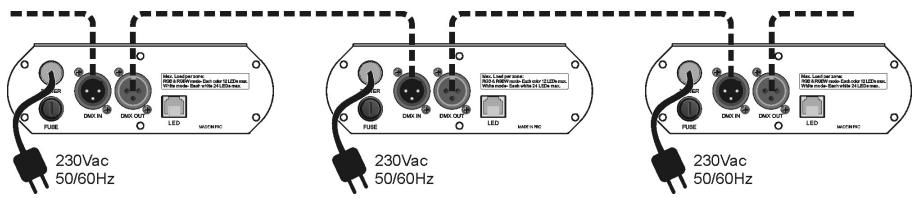
HOW TO SET THE RIGHT STARTING ADDRESS:
Refer to the next chapter (DMX-512 address setting) to learn how to set the starting address on this unit. The start address of each unit is very important. Unfortunately it is impossible to tell you in this user manual which start addresses you have to set because this completely depends on the controller you will use... So please refer to the user manual of your DMX-controller to find out which starting addresses you must set.
Example settings for different channel configurations:
1 Channel mode: 001(unit1),002(unit2),003(unit3), intervals of 1 channel
- 4 Channel mode: 001 (unit1), 005 (unit2), 009 (unit3), ... → intervals of 4 channels
- 11 Channel mode: 001 (unit1), 012 (unit2) → intervals of 11 channels
DMX-CONFIGURATION OF LD-POWER60 - MODE 1:

DMX-CONFIGURATION OF LD-Power60 - MODES 2 + 3:
DMX-CONFIGURATION OF LD-POWER60 - MODES 4 + 5 + 6 + 7
DMX-CONFIGURATION OF LD-Power120 MODE 6 + 7:
| DMX 512 Configuration (3 CHs) | DMX 512 Configuration (2 CHs) | |
| CH1/CH2 | CH 3 | CH1/CH2 |
| Mixing ratio | Dimmer | Dimmer |
| Warm White 0 Cool White | 255 0 0% | 255 0 0% |
HOW TO SETUP:
MAIN MENU:
- To select any of the menu options, press the MENU button up to when the required one is shown on the display.
- Select the function with the ENTER button. The display will blink.
- Use DOWN and UP button to choose the desired menu option.
- Once the required menu option is selected, press the ENTER button to select.
- Press the MENU button for 2seconds to save the settings and go back to normal working mode.
The menu structure is shown below.

DMX512 Address Setting
Used to set the starting address in a DMX setup.
- Press the MENU button until Addr is shown on the display.
- Press the ENTER button, the display starts blinking.
- Use DOWN and UP buttons to change the DMX512 address.
- Once the correct address shows on the display, press the ENTER button to confirm.
- Press the MENU button for about 2 seconds to save the setting and return to running mode, press shortly to return without saving.

Channel Mode
Used to set the desired channel mode.
- Press the MENU button until chid is shown on the display.
- Press the ENTER button, the display starts blinking.
-
Use DOWN and UP button to select one of the 7 working modes:
-
Modes 1 + 2 : used with RGBW projectors.
- Modes 3+4: used with RGB projectors.
- Modes 5+6: used with combined WW/CW projectors to control light temperature.
Mode 7: used for WW or CW projectors.
Check the different DMX-charts. - Once the correct address shows on the display, press the ENTER button to confirm.
- Press the MENU button for about 2 seconds to save the setting and return to running mode, press shortly to return without saving.
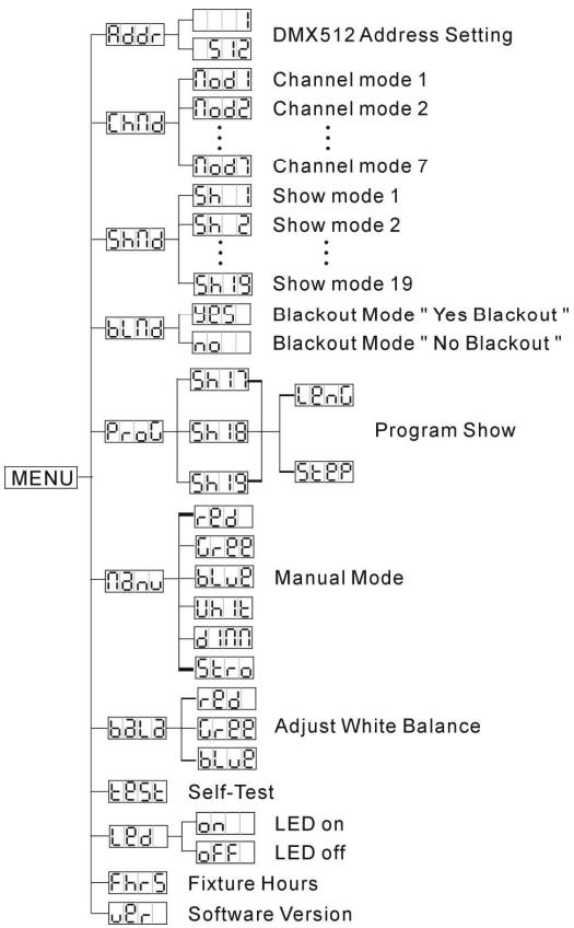

Show Mode
Used to select one of the 19 shows while used in standalone or master/slave mode.
- Press the MENU button until Shnd is shown on the display.
- Press the ENTER button to select.
- Use DOWN and UP buttons to select one of the 19 preprogrammed shows.
-
Press ENTER to confirm, now you also have to set:
-
Fade time: the display shows "Fxxx", where xxx ranges from 000 (corresponding to 0,256sec) to 255 (corresponding to 18 hours for 1 fade over)
-
Use DOWN and UP buttons to select desired fade time.
-
Press ENTER to confirm
- Wait time: the display shows "Uxxx", where xxx ranges from 000 (corresponding to 0,256sec) to 255 (corresponding to 18 hours waiting before the next fade over occurs)
- Use DOWN and UP buttons to select desired wait time.
-
Press ENTER to confirm (you will return to show selection)
-
Press the MENU button for about 2 seconds to save the setting and return to running mode, press shortly to return without saving.
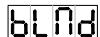
Blackout Mode
Blackout mode: when no DMX-signal is detected, the unit goes in blackout.
No blackout mode: when no DMX-signal is detected, the unit automatically switches to master mode.
- Press the MENU button until blnd is shown on the display.
- Press the ENTER button, the current selection starts blinking in the display.
- Use DOWN and UP button to select YES (blackout) or NO (no blackout) mode.
- Once the mode is selected, press the ENTER button to save it.
- Press the MENU button for about 2 seconds to save the setting and return to running mode, press shortly to return without saving.
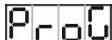
Program Mode
From the 19 shows, shows 17 to 19 can be edited by the user with a maximum of 42 steps.
- Press the MENU button until Pro is shown on the display.
- Press the ENTER button to select.
- Use DOWN and UP buttons to select one of the 3 user editable shows: 17, 18 or 19
-
Press ENTER to confirm, now you can edit the selected show:
-
Show length: a show can contain up to 42 steps, select how many steps of the show you want to use.
-
The display shows LEnO, press ENTER to see how many steps are currently selected.
- Use DOWN and UP buttons to adjust to the desired number of steps.
- Press ENTER to confirm.
-
Press the UP button to start programming the steps.
-
Programming each step: now we can start setting the different colors for each step.
-
The display shows SEER, press ENTER to see how many steps are selected.
- Use DOWN and UP buttons to select desired number of steps.
- Press ENTER to confirm.
- The display shows the first step (St 1), press ENTER to edit this step:
- [SET COLOR] The display shows Color (LD-POWER60) or - 1 / c - 2 (zone 1/2 on LD-POWER120), press ENTER to edit this color:
- Use DOWN and UP buttons to select one of the 255 colors.
- Press ENTER to confirm.
- [ADD WHITE] Press the UP button: the display shows UHT (LD-Power60) or U-1 / U-2 (zone 1/2 on LD-Power120).
- If you have RGBW projectors and want to add white, press ENTER and set the amount of white. If you only have RGB projectors: press the UP button again
- [SET DIMMER] The display shows d1 (LD-POWER60) or d - 1 / d - 2 (zone 1/2 on LD-POWER120), press ENTER to edit the output level for the current step:
- Use DOWN and UP buttons to set the level from 000 (off) to 255 (100%).
- Press ENTER to confirm.
- If all parameters for Step1 are OK, press the MENU button shortly followed by the UP button the display now shows the second step (St 2): you can adjust all settings for step2
- When all parameters are set, press the MENU button for 2seconds to return to working mode.
Manual Mode
Used to test all colors of the projectors connected to both output zones.
- Press the MENU button until Hnu is shown on the display.
-
Press the ENTER button to select: the display shows RD (LD-POWER60) or r-1 (LD-POWER120)
-
Use DOWN and UP buttons browse the different options:
For each option you can press ENTER, follow by the UP/DOWN buttons to set the desired level. Each time confirm with the ENTER button.
- rdd or r-1 (red for zone 1 on LD-POWER120)
- Green or Green (green for zone 1 on LD-Power120)
- blue or b-1 (blue for zone 1 on LD-Power120)
- U-1 or U-1 (white for zone 1 on LD-POWER120)
- (red for zone 2 on LD-POWER120)
- [green for zone 2 on LD-POWER120]
- b-2 (blue for zone 2 on LD-Power120)
U-2 (white for zone 2 on LD-POWER120)
Overall dimmer level) -
Sterd (overall strobe speed: values correspond to the strobe channel on the DMX chart)
-
After testing, just press the MENU button for about 2 seconds to return to running mode.
Adjust White balance
Makes it possible to adjust the white color when all colors are at maximum.
- Press the MENU button until bA1 is shown on the display.
- Press the ENTER button to select: all connected projectors turn to white color (all colors at maximum, except for white) while the display shows red (LD-Power60) or red (LD-Power120)
- Use DOWN and UP buttons browse the different options:
For each option you can press ENTER, follow by the UP/DOWN buttons to set the desired level. Each time confirm with the ENTER button.
- or (red for zone 1 on LD-POWER120)
- G - 1 (green for zone 1 on LD-POWER120)
- blue or b-1 (blue for zone 1 on LD-POWER120)
- (red for zone 2 on LD-Power120)
- (green for zone 2 on LD-POWER120)
-
b-2 (blue for zone 2 on LD-POWER120)
-
Press the MENU button for about 2 seconds to save the setting and return to running mode, press shortly to return without saving.
Remark: You can only set values between 125 and 255.
Self-Test
- Press the MENU button until Eose is blinking on the display.
- Press the ENTER button: the unit will run the built-in programmer for self-test.
- Press the MENU button for about 2 seconds to return to running mode.
Led Display
Display on: display is always on.
Display off: display is off when not used.
- Press the MENU button until the display shows
- Press the ENTER button.
- Use DOWN and UP buttons to select on (display always on) or OFF (display off when not used).
- Once the mode is selected, press the ENTER button.
(or automatically return to the main functions without any change after 8 seconds)
- Press the MENU button for about 2 seconds to save the setting and return to running mode, press shortly to return without saving.
Fixture Hours
Used to show the number of working hours of the unit.
- Press the MENU button until FhrS is shown on the display.
-
Press the ENTER button to show the number of working hours in the display.
-
Press the MENU button for about 2 seconds to return to running mode.

Software version:
Used to show the software version of the unit.
- Press the MENU button until Ucr is shown on the display.
- Press the ENTER button to show the software version of the unit.
- Press the MENU button for about 2 seconds to return to running mode.
SPECIFICATIONS
Power Input:
Fuse (LD-POWER60):
Fuse (LD-POWER120):
Power output (LD-POWER60):
Power output (LD-POWER120):
Max LED load per zone (RGB + RGBW):
Max LED load per zone (WHITE MODE):
DMX connections:
DMX channels used:
Size:
Weight (LD-POWER60):
Weight (LD-POWER60):
100Vac 240Vac 50 / 60Hz
250V 1A slow blow (20mm glass)
250V 2A slow blow (20mm glass)
1x zone 60W = 60Watt
2x zone 60W = 120Watt
max. 12 LEDs per color (total max. = 48pcs)
4 circuits, each supporting max. 12 LEDs (total max. = 48pcs)
3pin XLR male / female
2 to max 11 channels (depends on working mode)
see drawings
1,2kg
2,1kg
Every information is subject to change without prior notice
You can download the latest version of this user manual on our website: www.beglec.com
MODE D'EMPLOI
FONCTIONS (FACE AVANT)
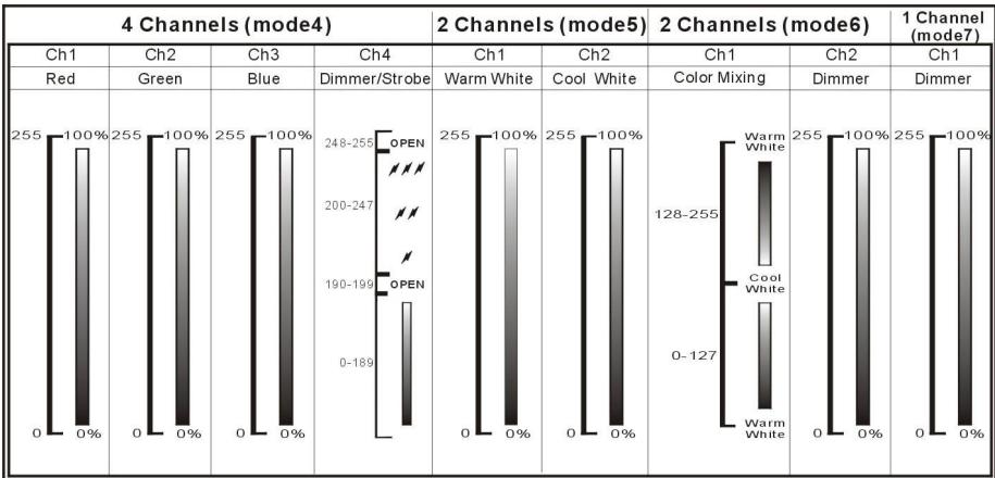
| 4 Channels (mode4) | 2 Channels (mode5) | 2 Channels (mode6) | 1 Channel (mode7) | |||||
| Ch1 | Ch2 | Ch3 | Ch4 | Ch1 | Ch2 | Ch1 | Ch2 | Ch1 |
| Red | Green | Blue | Dimmer/Strobe | Warm White | Cool White | Color Mixing | Dimmer | Dimmer |
| 255 | 100% | 255 | 100% | 248-255 | 100% | 255 | 100% | 255 |
| 0 | 0% | 0 | 0% | 200-247 | 0% | 0 | 0% | 0 |
| 0 | 0% | 0 | 0% | 190-199 | 0% | 0 | 0% | 0 |
| 0 | 0% | 0 | 0% | 0-189 | 0% | 0 | 0% | 0 |
DMX-CONFIGURATIE VAN DE LD-Power120 MODE 1:
| DMX 512 Configuration (11Channels) | ||||||
| CH1/CH5 | CH2/CH6 | CH3/CH7 | CH4/CH8 | CH 9 | CH 10 | CH 11 |
| Red | Green | Blue | White | Color Macro | Dimmer | Strobe |
| 255 100% | 255 100% | 255 100% | 255 100% | 248-255 Color 32 240-247 Color 31 232-239 Color 30 225-231 Color 29 217-224 Color 28 209-216 Color 27 102-208 Color 26 194-201 Color 25 186-193 Color 24 178-185 Color 23 171-177 Color 22 163-170 Color 21 155-162 Color 20 148-154 Color 19 140-147 Color 18 132-139 Color 17 124-131 Color 16 117-123 Color 15 109-116 Color 14 101-108 Color 13 093-100 Color 12 086-092 Color 11 078-085 Color 10 070-077 Color 9 0630-69 Color 8 055-062 Color 7 047-054 Color 6 038-046 Color 5 032-037 Color 4 024-031 Color 3 016-023 Color 2 008-015 Color 1 000-007 White | 255 100% 255 100% 255 100% 255 100% 255 100% 255 100% 255 100% 255 100% 255 100% 255 100% 255 100% 255 100% 255 100% 255 0% | 248-255 Open 240-247 Random Stroke Open Slow Close Fast Open Open 140-181 Slow Open Fast Close Open 132-139 Open 16-131 Open OFF |
DMX-CONFIGURATIE VAN DE LD-Power120 MODE 2 + 3:
| DMX 512 Configuration (8Channels) | DMX 512 Configuration (6 Channels) | |||||
| CH1/CH5 | CH2/CH6 | CH3/CH7 | CH4/CH8 | CH1/CH4 | CH2/CH5 | CH3/CH6 |
| Red | Green | Blue | White | Red | Green | Blue |
| 255 100% 0 0% | 255 100% 0 0% | 255 100% 0 0% | 255 100% 0 0% | 255 100% 0 0% | 255 100% 0 0% | 255 100% 0 0% |
DMX-CONFIGURATIE VAN DE LD-POWER120 MODE 4 + 5:
| DMX 512 Configuration (4 CHs) | DMX 512 Configuration (4 CHs) | ||||
| CH 1 | CH 2 | CH 3 | CH 4 | CH 1/CH3 | CH 2/CH4 |
| Red | Green | Blue | Dimmer/Strobe | Cool White | Warm White |
| 255 | 255 | 255 | 248-255 | 255 | 255 |
| 0% | 0% | 0% | 200-247 | 0% | 0% |
| 190-199 | 0% | 0% | |||
| 0-189 | |||||
DMX-CONFIGATIE VAN DE LD-POWER120 MODE 6 + 7:
| DMX 512 Configuration (3 CHs) | DMX 512 Configuration (2 CHs) | |
| CH1/CH2 | CH 3 | CH1/CH2 |
| Mixing ratio | Dimmer | Dimmer |
| Warm White 0 Cool White | 255 100% 0 0% | 255 100% 0 0% |
HOE INSTellen:
HOOFDMENU
Adjust White balance
1 zone van 60W = 60Watt
2 zones van 60W = 120Watt
max. 12 LEDs per kleur (total max. = 48stuks)
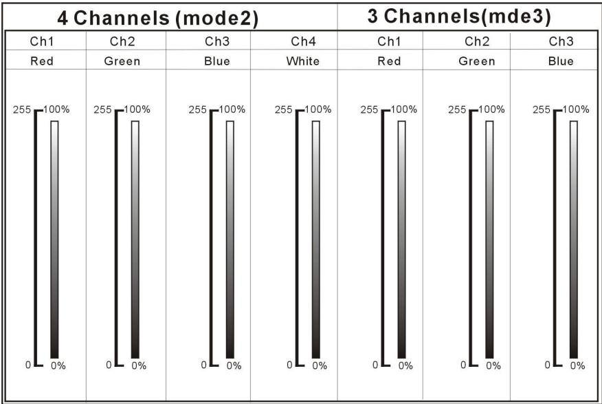
| 4 Channels (mode2) | 3 Channels(mde3) | |||||
| Ch1 | Ch2 | Ch3 | Ch4 | Ch1 | Ch2 | Ch3 |
| Red | Green | Blue | White | Red | Green | Blue |
| 255 100% | 255 100% | 255 100% | 255 100% | 255 100% | 255 100% | 255 100% |
| 0 0% | 0 0% | 0 0% | 0 0% | 0 0% | 0 0% | 0 0% |
DMX-KONFIGURATION DES LD-POWER60 - MODI 4 + 5 + 6 + 7:
| 4 Channels (mode4) | 2 Channels (mode5) | 2 Channels (mode6) | 1 Channel (mode7) | |||||
| Ch1 | Ch2 | Ch3 | Ch4 | Ch1 | Ch2 | Ch1 | Ch2 | Ch1 |
| Red | Green | Blue | Dimmer/Strobe | Warm White | Cool White | Color Mixing | Dimmer | Dimmer |
| 255 | 100% | 255 | 100% | 248-255 | 100% | 255 | 100% | 255 |
| 0 | 0% | 0 | 0% | 200-247 | 0% | 0 | 0% | 0 |
| 0-189 | 0-189 | 0% | 0-127 | 0-127 | 0-100% | |||
DMX-KONFIGURATION DES LD-POWER120 MODUS 1:
| DMX 512 Configuration (11Channels) | ||||||
| CH1/CH5 | CH2/CH6 | CH3/CH7 | CH4/CH8 | CH 9 | CH 10 | CH 11 |
| Red | Green | Blue | White | Color Macro | Dimmer | Strobe |
| 255 100% | 255 100% | 255 100% | 255 100% | 248-255 Color 32 240-247 Color 31 232-239 Color 30 225-231 Color 29 217-224 Color 28 209-218 Color 27 192-208 Color 26 184-201 Color 25 186-193 Color 24 178-195 Color 23 171-177 Color 22 163-170 Color 21 155-162 Color 20 148-154 Color 19 140-147 Color 18 132-139 Color 17 124-131 Color 16 117-123 Color 15 109-116 Color 14 101-108 Color 13 093-100 Color 12 086-092 Color 11 078-085 Color 10 070-077 Color 9 0630-69 Color 8 055-062 Color 7 047-054 Color 6 038-046 Color 5 032-037 Color 4 024-031 Color 3 016-023 Color 2 008-015 Color 1 000-007 White | 255 100% | 248-255 Open 240-247 Random Stroke 232-239 Open 190-231 Slow Close Fast Open 182-189 Open 140-181 Slow Open Fast Close 132-139 Open 16-131 Open OFF |
DMX-KONFIGURATION DES LD-POWER120 MODI 2 + 3:
| DMX 512 Configuration (8Channels) | DMX 512 Configuration (6 Channels) | |||||
| CH1/CH5 | CH2/CH6 | CH3/CH7 | CH4/CH8 | CH1/CH4 | CH2/CH5 | CH3/CH6 |
| Red | Green | Blue | White | Red | Green | Blue |
| 255 100% 0 0% | 255 100% 0 0% | 255 100% 0 0% | 255 100% 0 0% | 255 100% 0 0% | 255 100% 0 0% | 255 100% 0 0% |
DMX-KONFIGURATION DES LD-POWER120 MODI 4 + 5:
| DMX 512 Configuration (4 CHs) | DMX 512 Configuration (4 CHs) | ||||
| CH 1 | CH 2 | CH 3 | CH 4 | CH 1/CH3 | CH 2/CH4 |
| Red | Green | Blue | Dimmer/Strobe | Cool White | Warm White |
| 255 | 255 | 255 | 248-255 | 255 | 255 |
| 0% | 0% | 0% | 200-247 | 0% | 0% |
| 0% | 0% | 0% | 190-199 | 0% | 0% |
| 0% | 0% | 0% | 0-189 | 0% | 0% |
DMX-KONFIGURATION DES LD-POWER120 MODI 6 + 7:
| DMX 512 Configuration (3 CHs) | DMX 512 Configuration (2 CHs) | |
| CH1/CH2 | CH 3 | CH1/CH2 |
| Mixing ratio | Dimmer | Dimmer |
| Warm White 0 Cool White | 255 0 0% | 255 0 0% |