
DB-150 - Professional lighting JBSYSTEMS LIGHT - Free user manual and instructions
Find the device manual for free DB-150 JBSYSTEMS LIGHT in PDF.

| Product type | Professional power distribution bar for lighting |
| Brand | JBSYSTEMS LIGHT |
| Model | DB-150 |
| Dimensions (L x W x H) | 150 x 9 x 7 cm |
| Weight | 5 kg |
| Power supply | 230 V~ / 20 A max (4600 W) |
| Maximum total power | 4600 W (20 A) |
| Maximum power per channel | 2000 W |
| Number of output channels | 4 channels with Schuko sockets |
| Fuses per channel | 250 V / 8 A (20x5 mm) fast blow |
| Input fuse | 20 A automatic thermal |
| DMX connectors | Input: XLR male 3-pin; Output: XLR female 3-pin |
| Display | Multifunction LED screen with 4 navigation buttons |
| Operating modes | Dimmer (DIM) or switch (SWITCH) per channel, individually adjustable |
| Memory function | Output levels stored even when powered off (stand-alone mode) |
| Dimming curves | 3 selectable pre-programmed curves |
| Sliding mechanism | Allows distributing fixtures along the entire length of the bar |
| Fuse detection | LED per channel indicating a blown fuse |
| LED indicators | Mains presence and DMX signal |
| Stand adapter | 35 mm included; TV spigot 28 mm optional |
| Housing material | Aluminium |
| Max ambient temperature | 45 °C |
| Usage | Indoor use only |
| Cleaning | Soft cloth slightly damp; do not use solvents |
| Safety | Installation by qualified personnel; safety cable mandatory; min. distance 50 cm from walls |
Frequently Asked Questions - DB-150 JBSYSTEMS LIGHT
User questions about DB-150 JBSYSTEMS LIGHT
0 question about this device. Answer the ones you know or ask your own.
Ask a new question about this device
Download the instructions for your Professional lighting in PDF format for free! Find your manual DB-150 - JBSYSTEMS LIGHT and take your electronic device back in hand. On this page are published all the documents necessary for the use of your device. DB-150 by JBSYSTEMS LIGHT.
USER MANUAL DB-150 JBSYSTEMS LIGHT
Copyright © 2008 by BEGLEC cva.
Reproduction or publication of the content, even portions, in any manner, without express permission of the publisher, is prohibited.

V1.0

LIGHT RESEARCH
D8=150
4.6kW POWERED 4-BAR
Operation Manual EN
Mode d'emploi FR
Dispose of the unit and used batteries in an environment friendly manner according to your country regulations.
FR-DECLASSES L'APPAREIL
Thank you for buying this BRITEQ® product. To take full advantage of all possibilities, please read these operating instructions very carefully.
FEATURES
This unit is radio-interference suppressed. This product meets the requirements of the current European and national guidelines. Conformity has been established and the relevant statements and documents have been deposited by the manufacturer.
Professional aluminium Powered 4-bar: 4 × 2kW ( Max_tot = 4,6kW / 20A )
- Sliding mechanism: you can distribute your projectors evenly over the bar.
- Locking DMX in/outputs with POWER/DMX-present indicator
- 4 Digit LED display with 4 buttons for easy menu navigation:
- DMX address setting: each channel can have its own address
Each channel can be separately switched in dimmer or switch mode
- Separate dimmer preset with memory function for each channel (no controller needed)
4 High quality mains sockets (schuko)
- Standard 35mm top section adapter included (28mm TV-spigot optionally available)
- Mains power input with Neutrik Powercon and automatic fuse
- Individual channel fuses with "blown fuse" detectors
- All channels equipped with 40A triacs for increased reliability
BEFORE USE
Check the contents:
Check that the carton contains the following items:
DB-150 powered bar
- 4 sets of bolts and nuts used to install projectors
1 Stand adapter 35mm
1 Power cable
1 Lifting eye bold
- User manual
Some important instructions:
- Before you start using this unit, please check if there's no transportation damage. Should there be any, do not use the device and consult your dealer first.
- Important: This device left our factory in perfect condition and well packaged. It is absolutely necessary for the user to strictly follow the safety instructions and warnings in this user manual. Any damage caused by mishandling is not subject to warranty. The dealer will not accept responsibility for any resulting defects or problems caused by disregarding this user manual.
- Keep this booklet in a safe place for future consultation. If you sell the fixture, be sure to add this user manual.
- To protect the environment, please try to recycle the packing material as much as possible.
SAFETY INSTRUCTIONS:

CAUTION
RISK OF ELECTRIC SHOCK DO NOT OPEN

CAUTION: To reduce the risk of electric shock, do not remove the top cover. No user-serviceable parts inside. Refer servicing to qualified service personnel only.

The lightning flash with arrowhead symbol within the equilateral triangle is intended to alert the use or the presence of un-insulated "dangerous voltage" within the product's enclosure that may be of sufficient magnitude to constitute a risk of electric shock.

The exclamation point within the equilateral triangle is intended to alert the user to the presence of important operation and maintenance (servicing) instructions in the literature accompanying this appliance.
This symbol means: indoor use only
This symbol means: Read instructions
This symbol means: Safety Class II appliance
This symbol means: Lamp Control Gear

The device is suitable for mounting on standard flammable surfaces. Standard flammable surfaces include building materials such as wood and wood-based materials more than 2mm thick.
- To prevent fire or shock hazard, do not expose this appliance to rain or moisture.
- To avoid condensation to be formed inside, allow the unit to adapt to the surrounding temperatures when bringing it into a warm room after transport. Condense sometimes prevents the unit from working at full performance or may even cause damages.
- This unit is for indoor use only.
- Don't place metal objects or spill liquid inside the unit. No objects filled with liquids, such as vases, shall be placed on this appliance. Electric shock or malfunction may result. If a foreign object enters the unit, immediately disconnect the mains power.
- No naked flame sources, such as lighted candles, should be placed on the appliance.
- Prevent use in dusty environments and clean the unit regularly.
- Keep the unit away from children.
- Inexperienced persons should not operate this device.
Maximum save ambient temperature is 40^ . Don't use this unit at higher ambient temperatures. - Always unplug the unit when it is not used for a longer time or before you start servicing.
- The electrical installation should be carried out by qualified personal only, according to the regulations for electrical and mechanical safety in your country.
- Check that the available voltage is not higher than the one stated on the rear panel of the unit.
- The socket inlet shall remain operable for disconnection from the mains.
- The power cord should always be in perfect condition: switch the unit immediately off when the power cord is squashed or damaged. It must be replaced by the manufacturer, its service agent or similarly qualified persons in order to avoid a hazard
- Never let the power-cord come into contact with other cables!
- This appliance must be earthed to in order comply with safety regulations.
- In order to prevent electric shock, do not open the cover. There are no user serviceable parts inside.
- Never repair a fuse or bypass the fuse holder. Always replace a damaged fuse with a fuse of the same type and electrical specifications!
- In the event of serious operating problems, stop using the appliance and contact your dealer immediately
- Please use the original packing when the device is to be transported.
- Due to safety reasons it is prohibited to make unauthorized modifications to the unit.
MAINTENANCE
Clean by wiping with a polished cloth slightly dipped with water. Avoid getting water inside the unit. Do not use volatile liquids such as benzene or thinner which will damage the unit.
OVERHEAD RIGGING
- Important: The installation must be carried out by qualified service personal only. Improper installation can result in serious injuries and/or damage to property. Overhead rigging requires extensive experience! Working load limits should be respected, certified installation materials should be used, the installed device should be inspected regularly for safety.
- Make sure the area below the installation place is free from unwanted persons during rigging, de-rigging and servicing.
-
Locate the fixture in a well ventilated spot, far away from any flammable materials and/or liquids. The fixture must be fixed at least 50cm from surrounding walls.
-
The device should be installed out of reach of people and outside areas where persons may walk by or be seated.
- Before rigging make sure that the installation area can hold a minimum point load of 10 times the device's weight.
- Always use a certified safety cable that can hold 12times the weight of the device when installing the unit. This secondary safety attachment should be installed in a way that no part of the installation can drop more than 20cm if the main attachment fails.
- The device should be well fixed; a free-swinging mounting is dangerous and may not be considered!
- Don't cover any ventilation openings as this may result in overheating.
- The operator has to make sure that the safety-relating and machine-technical installations are approved by an expert before using them for the first time. The installations should be inspected every year by a skilled person to be sure that safety is still optimal.
FUNCTIONS
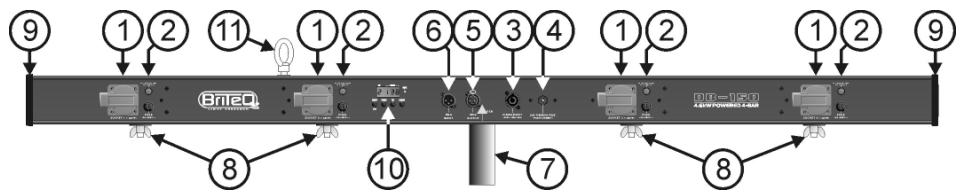
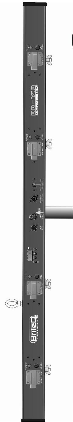
- CHANNEL OUTPUTS: Each channel output has its own output socket to connect any resistive and/or inductive projector(s) or small light effects.
- CHANNEL FUSES: Each channel is equipped with a fuse and "blown fuse" detector. The detector lights up when the channel fuse is blown. Always replace the blown fuse with a fuse that has the same characteristics! (250V/8A).
IMPORTANT NOTE: It's very important to know that the maximum load for each channel is rated at 2000Watts. However the total load for all 4 channels may not exceed 20A or 4600Watts!
- POWER INPUT: mains input, equipped with a Neutrik Powercon, make sure the local voltage is 230Vac and the projectors (and/or light effects) are properly connected to the channel output sockets (1) before you connect an earthed mains cable to this input. The maximum total load is 20A or 4600Watts.
- INPUT FUSE: This is an automatic circuit breaker. When the fuse is blown, first locate and solve the problem that caused the fuse to blow. When the problem is solved, simply push the button to reset the circuit breaker.
- DMX OUTPUT: 3pin female XLR-connector used to connect the DB-150 with the next unit in the DMX chain.
- DMX INPUT: 3pin male XLR-connector used to connect universal DMX-cables. This input receives instructions from a DMX-controller.
-
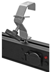
STAND ADAPTER: used to put the DB-150 easily on top of a light stand. Two different stand adapters can be used:
-
35mm adapter: (included) to be used on stands with a standard 35mm top section.
-
28mm TV-Spigot: (optional) to be used on stands equipped with a TV-spigot adapter on top.
-
SLIDING MECHANISM: used to distribute your projectors evenly over the DB-150. On the top rail you can install 2 clamps to fix the DB-150 easily under any ALU-truss. Also see number 9 for more information.
- END CAP: To install the bolts/nuts (needed to fix the projectors) and stand adapter you have to remove this end cap on one side of the unit: simply unscrew the 4 screws remove the cap put the nuts/bolts and/or stand adapter in the sliding rail put the cap back in place fix the 4 screws done!
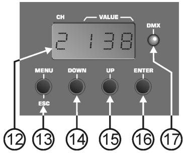
- CONTROL PANEL: multifunctional display + 4 buttons to navigate the setup menu. See the numbers below.
- SAFETY EYE: used to attach an optional safety cable when the DB-150 is fixed under ALU-truss (using clamps, also see n°8)
-
DISPLAY: Shows the software version shortly after switching on the unit. Further shows the information related to the selected function or working mode. The left digit shows the channel number, the 3 other digits show the channel status:
-
In the ADDR menu: channel + DMX address is shown, ranging from 001 to 512
- In the MODE menu: working mode is shown. ("DIM" = dimmer mode * "SW" = switch mode)
-
In the ALONE menu and standard display: channel output status is shown.
-
Channel in dimmer mode: dimmer percentage, ranging from 0% to 100% .
-
Channel in switch mode: "ON" = output 100% * "OFF" = output 0%
-
Curve : shows the dimming curve that is used
-
MENU BUTTON: Please refer to the menu structure to understand the different menus. These are the different possibilities:
-
Browse the main menu: Press the MENU button together with the UP/DOWN buttons.
-
Return to the main menu: Press the MENU button to return to the main menu. (escape function)
-
DOWN BUTTON: Please refer to the menu structure to understand the different menus. These are the different possibilities:
-
Browse the main menu: Press the MENU button together with the UP/DOWN buttons.
- In the ADDRESS menu: Press the DOWN button to lower the DMX address of the selected channel. (press the button for a longer time to increase the speed)
- In the MODE menu: Press the DOWN button to put the selected channel in switch or dimmer mode.
-
In the ALONE menu: Press the DOWN button to lower the dimmer value (0~100%) when the selected channel is in dimmer mode. (press the button for a longer time to increase the speed). When the selected channel is set to switch mode, you can turn the output on or off.
-
UP BUTTON: Please refer to the menu structure to understand the different menus. These are the different possibilities:
-
Browse the main menu: Press the MENU button together with the UP/DOWN buttons.
- In the ADDRESS menu: Press the UP button to increase the DMX address of the selected channel. (press the button for a longer time to increase the speed)
- In the MODE menu: Press the UP button to put the selected channel in dimmer or switch mode.
-
In the ALONE menu: Press the UP button to increase the dimmer value (0~100%) when the selected channel is in dimmer mode. (press the button for a longer time to increase the speed). When the selected channel is set to switch mode, you can turn the output on or off.
-
ENTER BUTTON: Please refer to the menu structure to understand the different menus. These are the different possibilities:
-
In the main menu: Press the ENTER button to select the desired sub menu.
-
In a sub menu: Press the ENTER button to browse through the 4 channels.
-
DMX PRESENT LED: this LED indicates if the unit receives a DMX-signal on the DMX-input (n^2) :
-
LED is on: no DMX-signal detected on the input.
- LED is blinking: DMX-signal detected on the input
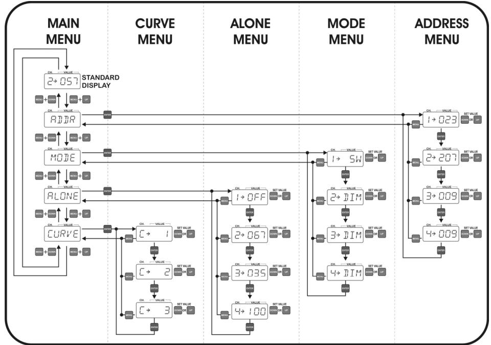
MENU STRUCTURE...
MAIN MENU:
This menu is used to select one of the 4 sub menus.
- Press the MENU button together with the UP/DOWN buttons to browse the menu.
- Press the ENTER button to select the desired submenu.
ADDRESS SUBMENU:
This menu is used to set the DMX address of the 4 output channels. Each channel can be set to a unique DMX-address. You can even give 2 or more channels the same DMX address.
- Press the ENTER button to browse through the submenu.
- Once you selected the desired channel, press the UP/DOWN buttons to set the address
- Press the MENU button to return to the main menu.
MODE SUBMENU:
This menu is used to set the working mode of the 4 output channels.
- DIM mode: use this mode when you connect lamps (projectors) to this output channel. You will be able to dim the output smoothly between 0% and 100% .
- SWITCH mode: use this mode when you connect small light effects to this output channel. You can toggle the output between ON (100% output) and OFF (0% output). Now you can switch small light effects on/off with your DMX-controller.
- Press the ENTER button to browse through the menu.
- Once you selected the desired channel, press the UP/DOWN buttons to set the working mode.
- Press the MENU button to return to the main menu.
ALONE SUBMENU:
This is the standalone mode; all output levels can be set directly on the control panel so you don't need a controller. It's important to know that the output settings are preserved when the unit is disconnected from the mains. This makes the DB-150 very useful to illuminate exhibition booths etc.
- Press the ENTER button to browse through the menu.
- Once you selected the desired channel, press the UP/DOWN buttons to set the output level.
- Press the MENU button to return to the main menu.
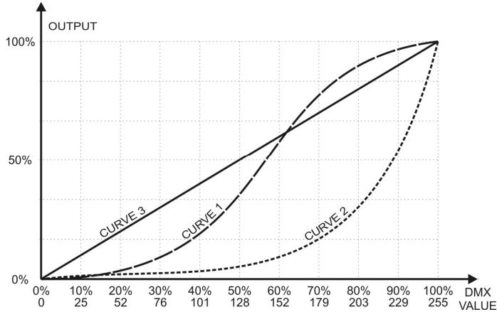
CURVE SUBMENU:
This menu is used to choose one of the 3 preprogrammed dimming curves. Please check the diagram with the dimming curves to see which curve suits most for your needs. Of course you can also simply try the dimmer curves...
SPECIFICATIONS
Power Input: 230Vac / 20A maximum (4600Watts)
Power outputs: 4x 230Vac / 2000Watts
Channel Fuses: 250V/8A (size 20x5mm)
Input fuse: 20A "auto reset" thermal circuit breaker
DMX input: 3pin XLR male
DMX output: 3pin XLR female
Size: 150 × 9 × 7 cm
Weight: 5,0kg
Every information is subject to change without prior notice
You can download the latest version of this user manual on our website: www.beglec.com