C 15 LI - Cordless drill driver FESTOOL - Free user manual and instructions
Find the device manual for free C 15 LI FESTOOL in PDF.

| Product type | Cordless drill/driver |
| Brand | Festool |
| Model | C 15 LI |
| Motor voltage | 14.4 - 15.6 V (Li-Ion) |
| No-load speed (1st gear) | 0 - 450 rpm |
| No-load speed (2nd gear) | 0 - 1,500 rpm |
| Max. torque (hard screwdriving) | 40 Nm |
| Max. torque (soft screwdriving) | 25 Nm |
| Adjustable torque (1st gear) | 0.5 - 8 Nm |
| Adjustable torque (2nd gear) | 0.5 - 6 Nm |
| Chuck capacity | 1.5 - 13 mm |
| Max. drilling diameter (wood) | 35 mm |
| Max. drilling diameter (metal) | 16 mm |
| Tool holder (in spindle) | 1/4\" (hex) |
| Weight (without battery, with Centrotec chuck) | 1.0 kg |
| Battery type | Li-Ion 14.4 V, 2.6 Ah (BPC 15 Li) |
| Charger | TRC 3 (input 120 V~ 60 Hz, output 7.2-18 V DC) |
| Charging time (80%) | approx. 45 min |
| Charging time (100%) | approx. 70 min |
| Main functions | Drilling, screwdriving, reversible rotation direction, variable speed, spindle brake, LED light, adjustable torque |
| Maintenance and cleaning | Clean the ventilation slots and connection contacts. Maintenance and repairs only by an authorized customer service center. |
| Safety | Read all instructions. Wear hearing protection, safety glasses, gloves. Use original Festool accessories. |
| Warranty | 3 years (1 year + 2 years free extension) |
| Included accessories | Centrotec chuck WH-CE, bit holder, belt clip, battery BPC 15 Li, charger TRC 3, Systainer |
Frequently Asked Questions - C 15 LI FESTOOL
User questions about C 15 LI FESTOOL
0 question about this device. Answer the ones you know or ask your own.
Ask a new question about this device
Download the instructions for your Cordless drill driver in PDF format for free! Find your manual C 15 LI - FESTOOL and take your electronic device back in hand. On this page are published all the documents necessary for the use of your device. C 15 LI by FESTOOL.
USER MANUAL C 15 LI FESTOOL
IMPORTANT: Read all instructions before using.
Guide d'utilisation
Page 17
Safety instructions 6
Technical data 8
Functional description 9
Intended use 9
Operation 10
Settings 11
Tool holder, attachments 11
Working with the machine. 13
Service and maintenance. 14
Accessories 14
Disposal 15
Transport 15
Warranty 15
Symbols
V volts
A amperes
Hz hertz
alternating current
no load speed
Class II Construction
rpm revolutions per minute
diameter
tip, hint
Warning of general danger
Risk of electric shock
Read the Operating Instructions/ Notes!
Wear ear protection.
Wear protective gloves.
Safety instructions
General safety instructions
WARNING! Read all safety warnings and all instructions. Failure to follow the warnings and instructions may result in electric shock, fire and/or serious injury.
Save all warnings and instructions for future reference.
The term "power tool" in the warnings refers to your mains-operated (corded) power tool or battery-operated (cordless) power tool.
1 WORK AREA SAFETY
a)Keep work area clean and well lit. Cluttered and dark areas invite accidents.
b) Do not operate power tools in explosive atmospheres, such as in the presence of flammable liquids, gases or dust. Power tools create sparks which may ignite the dust or fumes.
c)Keep children and bystanders away while operating a power tool. Distractions can cause you to lose control.
2 ELECTRICAL SAFETY
a) Power tool plugs must match the outlet. Never modify the plug in any way. Do not use any adapter plugs with earthed (grounded) power tools. Unmodified plugs and matching outlets will reduce risk of electric shock.
b) Avoid body contact with earthed or grounded surfaces, such as pipes, radiators, ranges and refrigerators. There is an increased risk of electric shock if your body is earthed or grounded.
c) Do not expose power tools to rain or wet conditions. Water entering a power tool will increase the risk of electric shock.
d) Do not abuse the cord. Never use the cord for carrying, pulling or unplugging the power tool. Keep cord away from heat, oil, sharp edges or moving parts. Damaged or entangled cords increase the risk of electric shock.
e)When operating a power tool outdoors, use an extension cord suitable for outdoor use. Use of a cord suitable for
outdoor use reduces the risk of electric shock.
f) If operating a power tool in a damp location is unavoidable, use a residual current device (RCD) protected supply. Use of an RCD reduces the risk of electric shock.
3 PERSONAL SAFETY
a) Stay alert, watch what you are doing and use common sense when operating a power tool. Do not use a power tool while you are tired or under the influence of drugs, alcohol or medication. A moment of inattention while operating power tools may result in serious personal injury.
b)Use personal protective equipment. Always wear eye protection. Protective equipment such as dust mask, non skid safety shoes, hard hat, or hearing protection used for appropriate conditions will reduce personal injuries.
c) Prevent unintentional starting. Ensure the switch is in the off-position before connecting to power source and/or battery pack, picking up or carrying the tool. Carrying power tools with your finger on the switch or energising power tools that have the switch on invites accidents.
d) Remove any adjusting key or wrench before turning the power tool on. A wrench or a key left attached to a rotating part of the power tool may result in personal injury.
e) Do not overreach. Keep proper footing and balance at all times. This enables better control of the power tool in unexpected situations.
f) Dress properly. Do not wear loose clothing or jewellery. Keep your hair, clothing and gloves away from moving parts. Loose clothes, jewellery or long hair can be caught in moving parts.
g)If devices are provided for the connection of dust extraction and collection facilities, ensure these are connected and properly used. Use of dust collection can reduce dust-related hazards.
4 POWER TOOL USE AND CARE
a)Do not force the power tool. Use the correct power tool for your applica
tion. The correct power tool will do the job better and safer at the rate for which it was designed.
b) Do not use the power tool if the switch does not turn it on and off. Any power tool that cannot be controlled with the switch is dangerous and must be repaired.
c) Disconnect the plug from the power source and/or battery pack from the power tool before making any adjustments, changing accessories, or storing power tools. Such preventive safety measures reduce the risk of starting the power tool accidentally.
d)Store idle power tools out of the reach of children and do not allow persons unfamiliar with the power tool or these instructions to operate the power tool. Power tools are dangerous in the hands of untrained users.
e) Maintain power tools. Check for misalignment or binding of moving parts, breakage of parts and any other condition that may affect the power tool's operation. If damaged, have the power tool repaired before use. Many accidents are caused by poorly maintained power tools.
f) Keep cutting tools sharp and clean. Properly maintained cutting tools with sharp cutting edges are less likely to bind and are easier to control.
g) Use the power tool, accessories and tool bits etc. in accordance with these instructions taking into account the working conditions and the work to be performed. Use of the power tool for operations different from those intended could result in a hazardous situation.
5 BATTERY TOOL USE AND CARE
a)Recharge only with the charger specified by the manufacturer. A charger that is suitable for one type of battery pack may create a risk of fire when used with another battery pack.
b) Use power tools only with specifically designated battery packs. Use of any other battery packs may create a risk of injury and fire.
c) When battery pack is not in use, keep it away from other metal objects like paper clips, coins, keys, nails, screws, or other small metal objects that can
make a connection from one terminal to another. Shorting the battery terminals together may cause burns or a fire.
d)Under abusive conditions, liquid may be ejected from the battery; avoid contact. If contact accidentally occurs, fl ush with water. If liquid contacts eyes, additionally seek medical help. Liquid ejected from the battery may cause irritation or burns.
6 SERVICE
a)Have your power tool serviced by a qualified repair person using only identical replacement parts. This will ensure that the safety of the power tool is maintained.
Machine-related safety instructions
- Wear ear protectors with impact drills. Exposure to noise can cause hearing loss.
- Use auxiliary handle supplied with the tool. Loss of control can cause personal injury.
- Hold power tools by insulated gripping surface when performing an operation where the cutting tool may contact hidden wiring or its own cord. Contact with a "live" wire will make exposed metal
parts of the tool "live" and shock the operator.
Health hazard by dust

WARNING! Various dust created by power sanding, sawing, grinding, drill-
ing and other construction activities
contains chemicals known (to the State of California) to cause cancer, birth defects or other reproductive harm. Some examples of these chemicals are:
- lead from lead-based paints,
crystalline silica from bricks and cement and other masonry products, and - arsenic and chromium from chemically-treated lumber.
The risk from these exposures varies, depending on how often you do this type of work. To reduce your exposure to these chemicals: work in a well ventilated
area, and work with approved safety equipment, such as dust masks that are specially designed to filter out microscopic particles. Wash hands after handling.

WARNING
TO REDUCE THE RISK OF INJURY, USER MUST READ INSTRUCTION MANUAL.
Technical data
| Cordless drill | C12 Li | C15 Li | |
| Motor voltage | 10.8 - 12 V | 14.4 - 15.6 V | |
| Idling speed* | 1st gear | 0 - 450 rpm | |
| 2nd gear | 0 - 1500 rpm | ||
| Max. torque | Soft material (wood) | 20 Nm | 25 Nm |
| Hard material (metal) | 34 Nm | 40 Nm | |
| Adjustable torque** | 1st gear | 0.5 - 8 Nm | |
| 2nd gear | 0.5 - 6 Nm | ||
| Chuck clamping range | 1.5 - 13 mm | ||
| Drill diameter max. | Wood | 25 mm | 35 mm |
| Metal | 14 mm | 16 mm | |
| Tool holder in drill spindle | 1/4 ″ | 1/4 ″ | |
| Weight without battery pack with Centrotec | 0.9 kg | 1.0 kg | |
| Charger | TRC 3 | |
| Mains voltage (input) | 120 V ~ | |
| Mains frequency | 60 Hz | |
| Charging voltage (output) | 7.2 - 18 V (DC) | |
| Rapid charging | max. 3 A | |
| Conservation charging current, pulsating | approx. 0.06 A | |
| Charging times for | LiIon 1.3 Ah/ 2.6 Ah, 80 % | approx. 22/ 45 min |
| LiIon 1.3 Ah/ 2.6 Ah, 100 % | approx. 35/ 70 min | |
| Permitted charging temperature range | -5 °C to +45 °C | |
| Temperature monitoring | via NTC resistor | |
| Battery pack | BPC 12 Li | BPC 15 Li |
| Order number | 497019 | 497020 |
| Voltage | 10.8 V | 14.4 V |
| Capacity | 1.3 Ah | 2.6 Ah |
| Weight | 0.3 kg | 0.6 kg |
| * Speed specifications with fully charged battery pack. | ** The maximum speed is reduced in the lower torque stages. | |
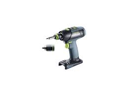
Functional description
The pictures for the functional description are on a fold-out page at the beginning of the instruction manual. When reading of the manual you can fold out this page for having always an overview of the machine.
[1-1] Torque thumbwheel
[1-2] Bit store
[1-3] LED lamp
[1-4] Gear switch
[1-5] Drilling symbol
[1-6] Screwdriving symbol
[1-7] Drilling/Fastening selector switch
[1-8] Right/left switch
[1-9] On/Off switch
[1-10] Belt clip
[1-11] Buttons for releasing the battery pack
Intended use
Cordless drills are suitable for drilling into metal, wood, plastics and similar materials as well as inserting and tightening screws.
The charger TRC 3 is design for charging the battery packs listed.

WARNING
The user bears the responsibility for damage and accidents caused by improper use; this also includes damage and wear caused by continuous use in industry.
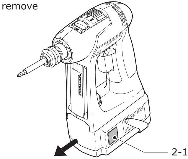
Changing the battery pack [2]
Removing the battery pack
Press and hold the two buttons [2-1].
Slide the battery pack forwards to remove.
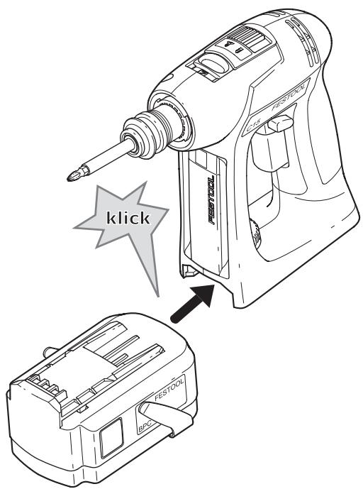
insert
2
Inserting the battery pack
▶ Slide the battery pack onto the retainer on the underside of the handle shown in Fig. until it engages..
Charging the battery pack [3]
① The battery pack is delivered partially charged. Charge the battery pack completely before using for the first time.
To charge the battery pack, slide all the way onto the retainer [3-1] on the charger.
To remove, slide off the charged battery pack in similar fashion.
![FESTOOL C 15 LI - Charging the battery pack [3] - 1](/content/2025/01/176768/images/d9ac276e314b0fc71f12fe2b0e2f08fe99fabab2fee9b40890856a5dac890fe9.jpg)
The charger TRC 3 can be used to charge all Festool battery packs of the BPS and BPC series. The charger automatically detects the type of the inserted battery (NiCd, NiMH or LiIon). A microprocessor controls the charging process in line with the charging state, temperature and voltage of the battery pack.
The LED [3-2] on the charger indicates the respective operating status of the charger.
LED yellow - lit continuously
Charger is ready to use.
LED green - flashing quickly
Battery pack is charged to maximum capacity.
LED green - flashing slowly
Battery pack is charged with reduced current, LiIon is charged to 80% .
LED green - lit continuously
Battery pack is fully charged, or charging is not started again, because the battery is charged to more than 80% .
LED red - flashing
Battery temperature is outside the permitted range.
LED red - lit continuously
General fault display, e.g. incomplete contact, short circuit, battery pack faulty, etc.
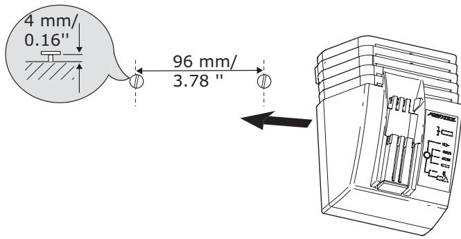
Charger wall mounting TRC 3
There are two elongated holes on the back of the TRC 3 for mounting the charger to a wall
using two screws (e.g. round head or flat head screw with shank diameter of 5 ~mm ).
Insert the two screws into the wall at a distance of 96~mm from one another and leave the screw heads protruding approx. 4mm .
Settings
Consider the pictures on the fold-out page.
Changing the direction of rotation
The right/left switch [1-8] changes the direction of rotation.
- Move switch from right to left = clockwise rotation
- Move switch from left to right = anticlockwise rotation
Changing gear
(1) Always switch off the machine before changing gear!
You can change gear using the gear switch [1-4].
- Switch forwards (Number 1 visible) = first gear
- Switch backwards (Number 2 visible) = second gear
Fastening
Adjust the switch [1-7] so that its marking faces the screw symbol [1-6]. The torque can be adjusted in this position.
(i) The switch-over function only works if the machine is switched off.
Adjust the torque accordingly at the torque wheel [1-1]:
Position 1 = low torque
Position 25 = high torque
The machine switches off when the preset torque is reached and an acoustic signal sounds. The machine only continues running when the on/off switch [1-9] is released and then pressed again.
Drilling
Adjust the switch [1-7] so that its marking faces the drilling symbol [1-5]. Maximum torque is set in this position.
Tool holder, attachments

WARNING
Risk of injury
Make sure that the machine is switched off and the battery pack has been removed before changing the tool holding fixture, attachments and tools.
Tool chuck CENTROTEC WH-CE
The tool chuck CENTROTEC WH-CE allows you to change tools with a CENTROTEC shank in a matter of seconds.
(1) Always use a CENTROTEC tool chuck to clamp CENTROTEC tools.

CAUTION
Risk of cutting injuries when changing the tool!
Wear protective gloves!
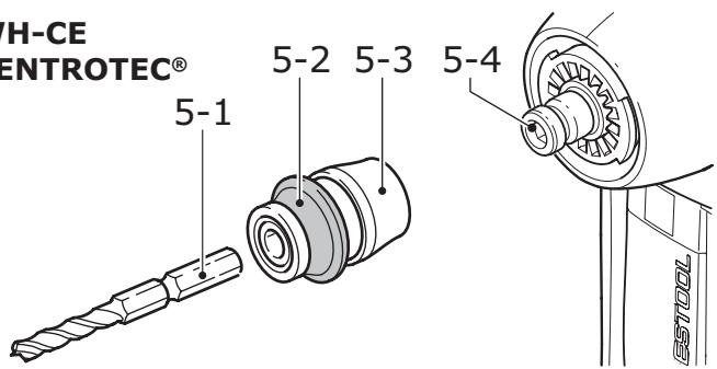
WH-CE CENTROTEC®
Attaching the CENTROTEC
Pull the release ring [5-3] forwards.
Attach the tool chuck to the drill spindle [5-4].
Release the ring [5-3].
Detaching the CENTROTEC
Pull the release ring [5-3] forwards.
Remove the tool chuck.
Changing tools
Pull back the green release ring [5-2] to attach or detach tools with a CENTROTEC shank.
- When attaching the tool, rotate until the hexagon shank [5-1] engages in the hexagon holder on the drill spindle.
Release the ring [5-2].
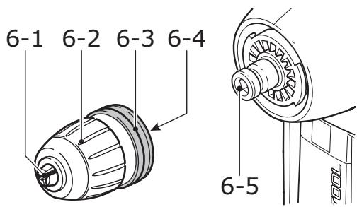
Chuck BF-FX
The chuck BF-FX is used for clamping drill and screwdriver bits.
BF-FX
Attaching the chuck BF-FX
Attach the chuck to the drill spindle [6-5].
Pull the release ring [6-3] forwards.
- Turn until the hexagon pin [6-4] on the chuck engages in the hexagon socket holder in the drill spindle.
Push the chuck all the way onto the drill spindle.
Release the ring [6-4].
Detaching the chuck BF-FX
Pull the release ring [6-4] forwards.
Remove the chuck.
Changing tools
Turn the clamping sleeve [6-2] anticlockwise to open the clamping jaws [6-1].
(1) The arrow on the spindle indicates the opening direction.
Insert the tool into the chuck.

CAUTION
Risk of injury
Clamp the tool centrally in the chuck!
Turn the clamping sleeve [6-2] clockwise to clamp the tool.
Angle attachment DD-AS
The angle attachment DD-AS (partly accessories) allows you to work (drill, fasten) vertically in relation to the longitudinal axis on the machine.
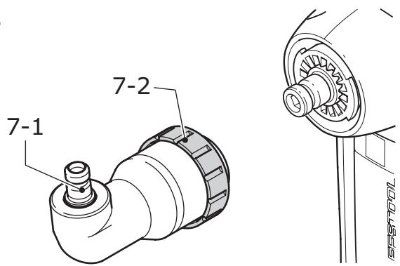
DD-AS
Fitting the angle attachment DD-AS
Fit the angle attachment to the drill spindle.
- Turn the attachment until it engages in the required position.
(1) You can engage the angle attachment in 16 different positions.
Turn the securing ring [7-2] firmly clockwise to lock the angle attachment.
Removing the angle attachment DD-AS
Turn the securing ring [7-2] anticlockwise all the way.
Remove the angle attachment.
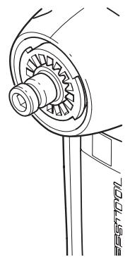
Attaching/Detaching the chuck
The chuck is secured to the shaft [7-1] of the angle attachment and the drill spindle on the machine in the same way.
Eccentric attachment DD-ES
The eccentric attachment (partly accessories) enables you to fasten close to abutting
edges. The tool holder was designed for bits in accordance with DIN 3126.
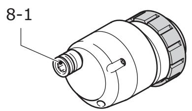
DD-ES
Attaching/Detaching eccentric attachment DD-ES
The eccentric attachment is attached/detached in the same way as the angle attachment (Section "Angle attachment DD-AS").
Attaching/Detaching the chuck
The chuck is secured to the shaft [8-1] of the eccentric attachment and the drill spindle on the machine in the same way.
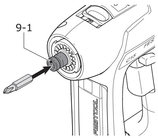
Tool holder in the drill spindle
Bits can be inserted directly in the hexagon socket holder on the drill spindle [9-1] to shorten and reduce the weight of the machine.
Working with the machine
Consider the pictures on the fold-out page.
Switch on/off
The switch [1-9] is an on/off switch (press = ON, release = OFF).
(1) The speed of the machine depends on how far the ON/OFF switch is pressed in.
① When the ON/OFF switch is released, the working spindle (chuck) stops immediately.
The LED lamp [1-3] lights up when the on/off switch [1-9] is pressed and lights up the working area.
Bit store
Bits or bit holders are inserted sideways into the bit store [1-2].
Acoustic warning signal
Acoustic warning signals sound and the machine switches off in the following operating states:

peep — —
- Battery flat or machine overloaded.
Change the battery.
Place the machine under reduced stress.

peep peep —
- Machine is overheating.
You must allow the machine to cool before using again.

peep peep peep
- LiIon battery pack is faulty or has overheated.
Once the battery pack has cooled, perform a functional check using the charger.

WARNING
Any maintenance or repair work that requires opening of the motor or gear housing should only be carried out by an authorised Customer Service Centre (name supplied by your dealer)!
- Maintenance or repair work carried out by an unauthorised person can lead to the wrong connection of the power leads or other components, which in turn can lead to accidents with serious consequences.
Observe the following instructions:
- Keep the air slits on the machine and the charger free and clean to ensure adequate cooling.
- Keep the contacts on the machine, charger and battery pack clean.
Information on battery packs
- Where possible, store the battery pack in a cool, dry place at a temperature between 5^ C and 25^ C .
- Battery packs are most efficient at temperatures between 20^ C and 30^ C .
- Protect the battery pack from moisture, water and heat.
- Significantly shorter operating times after each charge indicate that the battery pack is worn and should be replaced with a new one.
- The LiIon battery pack is fully compatible with the charger! Integrated electronics prevent overloading and overheating during the charging process.
- Do not leave flat battery packs in a charger disconnected from the mains power supply for longer than one month. There is a risk of total discharge and the maximum power of the battery pack may decrease.
- Store the battery pack in its packaging to reduce the risk of short circuits..
- If LiIon battery packs are to be stored for long periods without use, they should be charged to 40 % capacity (approx. 15 mins. charging period).
Accessories
Use only original Festool accessories and Festool consumable material intended for this machine because these components are designed specifically for the machine. Using accessories and consumable material from other suppliers will most likely affect the quality of your working results and limit any warranty claims. Machine wear or your own personal workload may increase depending on the application. Protect yourself and your machine, and preserve your warranty claims by always using original Festool accessories and Festool consumable material!
The accessory and tool order number can be found in yout festool catalog or on the Internet at „www.festool-usa.com".
Systainer
Many Festool products are shipped in a unique system container, called "Systainer".
This provides protection and storage for the tool and accessories. The Systainers are stackable and can be interlocked together. They also can be interlocked atop Festool CT dust extractors.
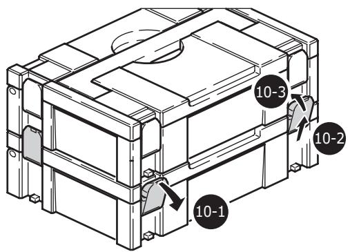
Place one systainer on top of the other.
Release all four latches on the lower systainer by pulling back at their top edges [10-1].
▶ Slide all four latches upward [10-2].
Snap all four latches back to their flat position [10-3] so they engage the stacking tabs of the upper systainer.
Disposal
Do not throw the power tool in your household waste!! Dispose of machines, accessories and packaging at an environ-
mentally responsible recycling centre. Observe the valid national regulations.
Transport
The equivalent amount of lithium in the LiIon battery pack is less than the applicable limit value and certified as per UN manual ST/SG/ AC.10/11/rev. 3 part III, subsection 38.3. The LiIon battery pack is therefore not subject to national and international dangerous
goods regulations, neither as an individual component nor as a fitted machine component. However, dangerous goods regulations may apply when several battery packs are transported, in which case you may have to fulfil special conditions
Warranty
Conditions of 1+2 Warranty
You are entitled to a free extended warranty (1 year + 2 years = 3 years) for your Festool power tool. Festool shall be responsible for all shipping costs during the first year of the warranty. During the second and third year of the warranty the customer is responsible for shipping the tool to Festool. Festool will pay for return shipping to the customer using UPS Ground Service. All warranty service is valid 3 years from the date of purchase on your receipt or invoice.
Festool Limited Warranty
This warranty is valid on the pre-condition that the tool is used and operated in compliance with the Festool operating instructions. Festool warrants, only to the original consumer purchaser, that the specified tool will be free from defects in materials and workmanship for a term of one year from the date of procurement. Festool makes no other warranty, express or implied, for Festool portable power tools. No agent, representative, distributor, dealer or employee of Festool has the authority to increase or otherwise change the obligations or limitations of this warranty. The obligations of Festool in its sole discretion under this warranty shall be limited to the repair or replacement of any
Festool portable power tool that is found to be defective as packaged with the User Manual.
Excluded from coverage under this warranty are: normal wear and tear; damages caused by misuse, abuse or neglect; damage caused by anything other than defects in material and workmanship. This warranty does not apply to accessory items such as circular saw blades, drill bits, router bits, jigsaw blades, sanding belts, and grinding wheels. Also excluded are "wearing parts", such as carbon brushes, lamellas of air tools, rubber collars and seals, sanding discs and pads, and batteries.
Festool portable power tools requiring replacement or repair are to be returned with the receipt of purchase to Festool (call 800-554-8741 for address details).
IN NO EVENT SHALL FESTOOL BE LIABLE FOR ANY CONSEQUENTIAL OR INCIDENTAL DAMAGES FOR BREACH OF THIS OR ANY OTHER WARRANTY, EXPIRESSED OR IMPLIED WHATSOEVER. ALL WARRANTYES IMPLIED BY STATE LAW, INCLUDING THE IMPLIED WARRANTY OF MERCHANTABILITY AND FITNESS FOR A PARTICULAR PURPOSE,
ARE HEREBY LIMITED TO THE DURATION OF THREE YEARS.
Some states in the U.S. and some Canadian provinces do not allow the limitations on how long an implied warranty lasts, so the above limitation may not apply to you. With the exception of any warranties implied by state or province law as hereby limited, the foregoing
express limited warranty is exclusive and in lieu of all other warranties, guarantees, agreements and similar obligations of Festool.
This warranty gives you specific legal rights and you may also have other rights which vary from state to state in the U.S. and province to province in Canada.
Sommaire
Symboles 17
Position 1 = petit couple,
Position 25 = grand couple