
DFM 4X4 - Professional audio equipment AKG - Free user manual and instructions
Find the device manual for free DFM 4X4 AKG in PDF.

| Product Type | Multi-channel Audio Processor |
| Brand | AKG |
| Model | DFM 4X4 |
| Number of Audio Channels | 4 balanced inputs / 4 balanced outputs |
| Power Supply | Included 20 V DC power adapter |
| Control Software | LecNet for AKG (PC, RS-232 connection) |
| Main Functions | Equalization, filters (ADF anti-feedback, Notch, band-pass, etc.), compressors, limiters, audio delay, routing matrix, programmable inputs/outputs |
| Anti-feedback Protection | Automatic per-channel ADF (Anti Digital Feedback) |
| Internal Memories | 8 non-volatile presets |
| Control Inputs | 13 programmable pins (contact or 0-5 V DC) |
| Control Outputs | 8 programmable pins (ground contact, max 40 V / 100 mA) |
| Daisy-chain Connectivity | EXPANSION IN/OUT connectors for chaining multiple units |
| Included Accessories | Power adapter, RS-232 cable, LecNet extension cable, software CD-ROM |
| Care and Cleaning | Slightly damp cloth, disconnect power adapter before cleaning |
| Safety | Do not open, avoid liquids, use only the supplied adapter, respect mains voltage |
| Application Areas | Professional sound reinforcement, fixed installations, multi-channel audio processing |
| Compliance | CE, RoHS (estimated) |
Frequently Asked Questions - DFM 4X4 AKG
User questions about DFM 4X4 AKG
0 question about this device. Answer the ones you know or ask your own.
Ask a new question about this device
Download the instructions for your Professional audio equipment in PDF format for free! Find your manual DFM 4X4 - AKG and take your electronic device back in hand. On this page are published all the documents necessary for the use of your device. DFM 4X4 by AKG.
USER MANUAL DFM 4X4 AKG
Please read before using the equipment!
- Spill no liquids on the equipment and do not drop any objects through the ventilation slots in the equipment.
- The equipment may be used in dry rooms only.
- The equipment may be opened, serviced, and repaired by authorized personnel only. The equipment contains no user-serviceable parts.
- Before connecting the equipment to power, check that the AC mains voltage stated on the supplied AC adapter is identical to the AC mains voltage available where you will use the equipment.
- Operate the equipment with the supplied 20-V AC adapter. Using adapters with a DC output and/or a different output voltage may cause serious damage to the unit.
- If any solid object or liquid penetrates into the equipment, shut down the sound system immediately. Disconnect the AC adapter from the power outlet immediately and have the equipment checked by AKG service personnel.
- If you will not use the equipment for a long period of time, disconnect the AC adapter from the power outlet. Please note that the equipment will not be fully isolated from power when you set the power switch to OFF.
- Do not place the equipment near heat sources such as radiators, heating ducts, or amplifiers, etc. and do not expose it to direct sunlight, excessive dust, moisture, rain, mechanical vibrations, or shock.
- To avoid hum or interference, route all audio lines, particularly those connected to the microphone inputs, away from power lines of any type. If you use cable ducts, be sure to use separate ducts for the audio lines.
- Clean the equipment with a moistened (not wet) cloth only. Be sure to disconnect the AC adapter from the power outlet before cleaning the equipment! Never use caustic or scouring cleaners or cleaning agents containing alcohol or solvents since these may damage the enamel and plastic parts.
-
Use the equipment for the applications described in this manual only. AKG cannot accept any liability for damages resulting from improper handling or misuse.
-
The AC adapter will draw a small amount of current even when the equipment is switched off. To save energy, disconnect the AC adapter from the power outlet if you will leave the equipment unused for a long period of time.
- When scrapping the equipment, separate the case, circuit boards, and cables, and dispose of all components in accordance with local waste disposal rules.
1.1 Safety
1.2 Environment
2 Description

The DFM4x4 offers some of the most versatile multichannel signal processing available. With 4 channels of audio signal processing plus Automatic Digital Feedback Elimination (ADF E) on each channel, the DFM4x4 is a compact solution for a wide variety of sound system applications. With 13 Programmable Inputs and 8 Programmable Outputs configurable into 8 non-volatile pre-set memory positions the DFM4x4 assures you complete flexibility. For more details refer to the DFM4x4 Owner's Manual. If you are still haunted by unanswered questions, call the AKG product specialist for SR products, Mr. J. Bakker at 43 1 866 54 1395 or email to bakkerj@akg.com
1xDFM4x4
1 x AC adapter
1 x CD-ROM with "LecNet for AKG" software
1 x RS-232 cable
1 x LecNet expansion cable
2.1 Introduction
2.2 Packing List
3 Interfacing
Connect your signal sources to the INPUTS on the DFM4x4 rear panel.
The DFM4x4 is equipped with 4 balanced inputs but does accept unbalanced signals.
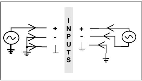
3.1 Audio Inputs
Fig. 1: Connecting unbalanced (left) and balanced (right) signal sources.
3.2 Audio Outputs
Connect the rear panel OUTPUTS to the desired inputs.
The DFM4x4's OUTPUTS are balanced.
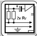
In order to use an output in the unbalanced line level mode, take the signal from the "+" OUTPUT connection and the OUTPUT ground.
Important: Leave the "-" output floating.
Connect your computer to the DFM4x4 with the supplied RS-232 cable.
- Connect the cable on the supplied AC adapter to the PWR IN jack on the DRM4x4 rear panel.
- Connect the AC adapter to a convenient power outlet.
3.3 Connecting to the Computer
3.4 Connecting to Power
3.5 EXPANSION IN/OUT
To daisy-chain several DFM4x4s, use the supplied LecNet expansion cable to the EXPANSION OUT socket on the first unit to the EXPANSION IN socket on the next unit, and so on.
You will find that there is no "Master/Slave" switch on the DFM4x4. There is no Master/Slave notion in the interconnection between DFM4x4s because there is no audio signal transmitted through the LecNet expansion cable. (See other LecNet manuals).

4 Operating Notes
4.1 Installing the Software
- Insert the CD-ROM into your drive. The installation program will start automatically.
- Follow the on-screen instructions.
- Enter your name and company name when asked and we you to accept the default directory.
- If you are not familiar with the LecNet software we recommend you to choose "Typical" installation.
- Click on "Next" and accept the given setting by double-clicking on "Next" again.
- To complete the installation, click on "Finish" when asked for.
- You can now start the software anytime by clicking on "Start/Program/LecNet for AKG".
4.2 Setting Up your Software
Before starting the program:
- Check that the DFM4x4 is connected to your computer. If it is not, use the supplied RS-232 cable to connect the DFM4x4 to the computer. Switch power to the DFM4x4 ON.
- Prior to all manipulation and interconnection make sure you have equipped all the devices with a unique address, a number between 128 and 256. To change an address, connect only one device to the computer and if using an AS16x12 or AS8, place it in "MASTER" mode.
4.2.1 Selecting Devices
- Launch the software at "Start/Programs/LecNet for AKG/LecNet Master Pro" or double click on the shortcut to LecNet Master Pro you might have created on your desktop.
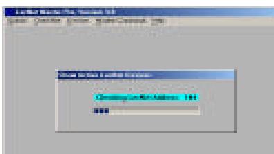
The LecNet program will run a check to see which devices are connected to your computer, thus automatically find the DFM4x4 you have linked to your computer.
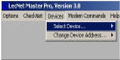
Fig. 2: Checking LecNet Addresses...
- In the Lecnet Master Pro screen that has popped up, click on "Devices/Select Device....". The addresses of all your connected devices will pop up.
- Click on the device you want to program. This will get you to an active programming screen for your DFM4x4.
Fig. 3: Programming screen for the DFM 4x4.
4.2.2 Input Gain
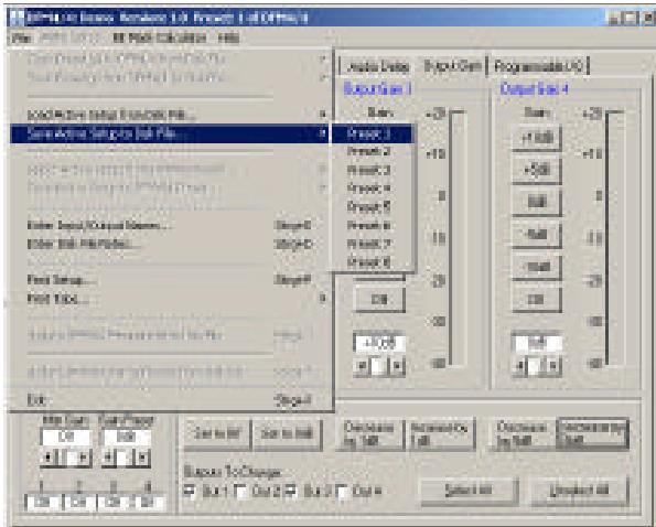
Fig. 4: Setting input gain, seting up the matrix, saving settings.
- In the "Input Gain" tab you can fine adjust your input gain and set the minimum and maximum values for remote control via the Programmable Inputs.
- When finished in a tab save your setting in a Preset by clicking on "File/Save Active Setup to Disk File...." to save it on your computer or "Save Active Setup to DFM4x4 Preset" to save it on the DFM4x4.
4.2.3 Matrix Setup
- Click on the "Matrix Setup" tab and set up your Matrix.
- Save your settings to a Preset.
4.2.4 Output Gain
- Click on the "Output Gain" tab and set your Output gains as well as the minimum and maximum values for remote control via the Programmable Inputs.
The "Master Output" section enables you to apply gain changes to several outputs at the same time. -
Save your settings to a Preset.
-
Click on the "Filter Setup" tab and select the output you want to work on.
- Click on the first filter. The filter will be highlighted in yellow.
- Select the type of filter you want to use from the "Filter Type" list.
All filters, except for the ADFE Notch, have adjustable frequencies from 20Hz to 20kHz . The bandwidth of the filters that support adjustable bandwidth are selectable from 0.5 octaves to 2.55 octaves. The scale of the Frequency Response screen is selectable between ± 15dB and ± 30dB .
- We advise you to carefully listen to the changes you have made and stop equalizing as soon as the sound is acceptable.
- Once the room is equalized, set an ADFE and start to turn up the volume to a point where feedback sets in. The ADFE will notch the frequency at which the first feedback occurs.
Repeat this until you have achieved an acceptable
volume level. Three or four fixed ADFEs, after having equalized the room, would still be OK. (Should you need more you may want to check if your problem should not be solved acoustically.)
- If you have some free filters left you can set these up as supplementary ADFEs: Click on the filter. The filter will be highlighted in yellow. Select "ADF E" from the "Filter Type" list. DO NOT turn up the volume so the frequency will not be determined.
In use, the ADFE will react on occurring feedback and reset itself when you switch power to the DFM4x4 off. - Save your settings to a Preset.
The compressors allow you to control the dynamic range of the audio signal.
- Click on the "Compressor" tab to access the compressor parameters.
- Start by selecting the desired "Compression Ratio". You can select the "Compression Ratio" from 1:1 (no compression) to 5:1 (heavy compression).
- Set "Threshold" (the level at which compression starts), "Attack Time" (determining how fast the compressor reacts when the signal is superior to the threshold level), and "Release Time" (the time within which compression stops as the signal level drops below threshold again).
Note: A short attack time, excessively long release time, and a high compression ratio may cause "pumping" effects. - Save your settings to a Preset.
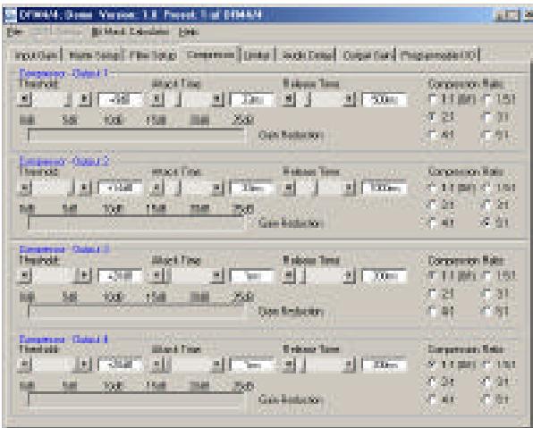
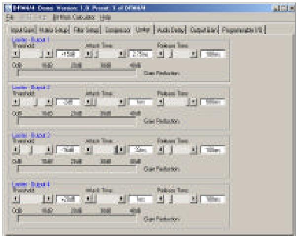
Fig. 7: "Limiter" screen.
4.2.5 Filters
Fig. 5: Setting up filters.
4.2.6 Compressors
Fig. 6: "Compressor" screen.
4.2.7 Limiter
The limiters allow you to set an absolute ceiling to the output level.
- Click on "Limiter". Except for Ratio, the limiters provide the same parameters as the compressors.
- Set "Threshold" (the level the output signal must never exceed), "Attack Time" (determining how fast you want the limiter to react when the signal reaches the threshold level), and "Release Time" (the time within which gain reduction stops as the signal level drops below threshold again).
- Save your settings to a Preset.
4.2.8 Delay
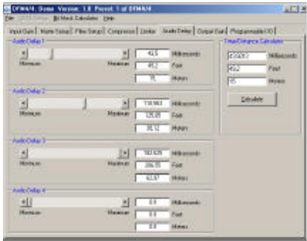
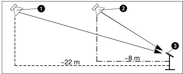
Fig. 8: "Delay" screen.
Fig. 9: Front speaker (1), delayed rear speaker (2), microphone (3).
4.2.9 Programmable Inputs
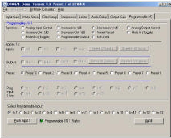
Fig. 10: "Programmable I/O" tab, Example 1.
4.2.10 Programmable Outputs
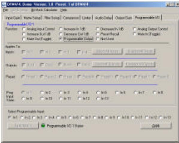
Fig. 11: "Programmable I/O" tab, Example 2.
To provide a consistent sound throughout a long and narrow hall, you will need a distributed speaker system. You can set up the delays required for the rear speakers as follows:
- Record a plop or a bang on a snare drum.
- Place a microphone roughly 8 meters from the first rear speakers (2).
- Measure the distance between the front (principal) speakers (1) and the first rear speakers (2).
- Click on "Audio Delay".
- Enter the distance you measured in the "Feet" field (or the "Meters" field if you measured in meters).
- Put on a pair of good headphones (e.g., AKG K 240 or K 270).
- Play the plop or snare drum beat you have recorded in a loop through the sound system and adjust "Audio Delay" to the point that the sounds coming from the front speakers (1) and the rear speakers (2) coincide (you hear only one plop).
- Repeat steps 1 through 7 for all other delayed speakers (2).
-
Save your settings to a Preset.
-
Click on "Programmable I/O".
- Select the Programmable Input you would like to program (In 1 to In 13) from the "Select Programmable Input" list on the bottom of the tab.
- Select the function you would like to execute, a "Preset Recall" in Example 1.
- In the "Preset" line, mark the Preset you want to recall. If your function is an analog input or output control, increase or decreases in volume, or a signal mute, select the corresponding input or output from "Applies To: Inputs" or "Applies To: Outputs".
- Click on "Apply".
-
Save your settings to a Preset. Note that a Programmable Input pin can have a different function in every Preset.
-
Click on "Programmable I/O".
- To select the Programmable Output you would like to program, click on a channel between In 1 and In 8 in the "Select Programmable Input" list on the bottom of the tab.
- In the "Function" field, click on "Programmable Output" to define the selected pin as a Programmable Output.
- Select the Programmable Input whose current state you want to indicate from the "Prog Input State" list.
In Example 2 (fig. 11), pin 1 is defined as a Programmable Output. Therefore, "In 1" in the "Prog Input State" list is gray.
Note: You cannot assign the same pin to two functions in the same Preset.
- Save your settings to a Preset.
As with the Programmable Inputs, you can assign a different function to each Programmable Output in each Preset.
The 13 Programmable Input pins can control a variety of DFM4x4 parameters. Each input can respond to either a contact closure or a continuous voltage. Figs. 12 to 14 show some common connections to the Programmable Input pins.
Each Programmable Input is internally pulled up though a 100K resistor to +5 VDC, so no external pull-ups are necessary. When using a continuous voltage with one of the Programmable Inputs, set the function of the Programmable Input to either "Analog Input Control" or "Analog Output Control" in the "Function" line on the "Programmable Input" tab in the control panel of the LecNet software.
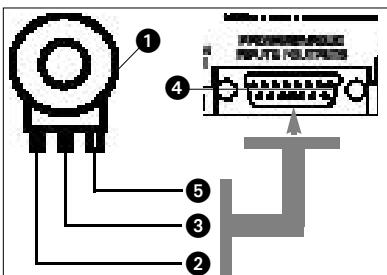
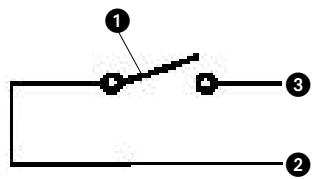
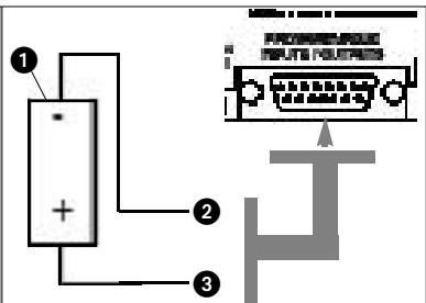
Fig. 14: DC voltage source (1), continuously adjustable from 0V to +5V .
4.3 Wiring
Programmable Input Pins
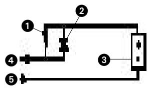
Fig. 12: Using a 10k linear pot (1) for analog gain control.
2 = CCW - > ground.
3 = Center pin -> Programmable Input pin (4).
5 = CW - > + 5V
Fig. 13: Contact closure (1).
2 = ground,
3 = connection to Programmable Input pin.
2 = ground,
3 = connection to Programmable Input pin.
Figs. 12 to 14.
The 8 Programmable Output pins of the DFM4x4 can indicate the current state of a Programmable Input.
Each Programmable Output is the electrical equivalent of a contact closure to ground. When a Programmable Output is "active", it conducts current to ground. The maximum acceptable voltage for each Programmable Output is 40V and they will safely conduct up to 100mA DC continuous.
You may run LEDs from the +5 VDC pin on the Programmable Input connector as long as the total LED current for all LEDs on does not exceed 100 mA.
Similarly, you may also run 5-V relay coils from the +5 VDC pin on the Programmable Input connector, as long as the total coil current does not exceed 100mA .
Note that fig. 17 shows an external DC source powering the relay coil. This will be necessary if coil voltages above 5V are needed.
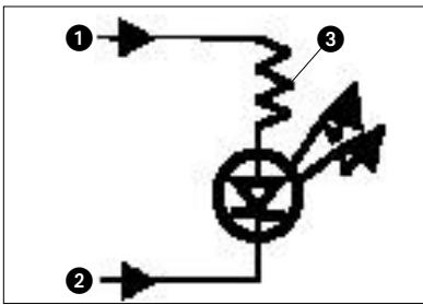
Figs. 15 to 17 show some common connections to Programmable Output pins.
Figs. 15 to 17.
4.4 Wiring
Programmable Output Pins
Fig. 15: LED is ON when the Programmable Output is active.
1 = +5 VDC from Programmable Input pin 14
2 = Programmable Output pin
3 = 380
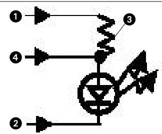
Fig. 16: LED is OFF when the Programmable Output is active.
1 = +5 VDC from Programmable Input pin 14
2 = Programmable Output pin
3 = 380
4 = Gnd (from programmable output pin 15)
Fig. 17: Relay is ON when the Programmable Output is active. Max. coil current is 100mA .
1 = Relay coil
2 = 1N001 diode or equivalent
3 = External DC voltage source (<40 VDC)
4 = Programmable Output pin
5 = Gnd (from programmable output pin 15)
1.1 Sécurité
3.5 Prese EXPANSION IN/OUT
Conecte as fontes de sinais com as conexões INPUT no lado traseiro do DFM4X4.
3.5 As tomas EXPANSION IN/OUT
914 Airpark Center Drive, Nashville, TN 37217, U.S.A., Tel: (615) 620-3800, Fax: (615) 620-3875, http://www.akgusa.com, e-mail: akgusa@harman.com
For other products and distributors worldwide visit http://www.akg.com
- Safety
- Environment
- Description
- Introduction
- Packing List
- Interfacing
- Audio Inputs
- Audio Outputs
- Connecting to the Computer
- Connecting to Power
- EXPANSION IN/OUT
- Operating Notes
- Installing the Software
- Setting Up your Software
- Selecting Devices
- Input Gain
- Matrix Setup
- Output Gain
- Filters
- Compressors
- Limiter
- Delay
- Programmable Inputs
- Programmable Outputs
- Wiring
- Programmable Input Pins
- Wiring
- Programmable Output Pins
- Sécurité
- Prese EXPANSION IN/OUT
- As tomas EXPANSION IN/OUT
Brand : AKG
Model : DFM 4X4
Category : Professional audio equipment