
GN30E - Microphone AKG - Free user manual and instructions
Find the device manual for free GN30E AKG in PDF.

| Product Type | Microphone mounting module (gooseneck) |
| Brand | AKG |
| Model | GN30E |
| Modular system | Discreet Acoustics Modular |
| Power | Phantom 9–52 V per IEC 61938 |
| Connectivity | Integrated DPA XLR adapter (3-pin XLR) |
| Gooseneck length | 380 mm |
| LED ring | LED (indicates operating status) |
| Bass attenuation | Switchable (-6 dB at 200 Hz) by removing jumper J2 |
| Capsule compatibility | CK31 (cardioid), CK32 (omnidirectional), CK33 (hypercardioid), CK47, CK80 |
| Polar pattern | Variable depending on capsule |
| Frequency response | Variable depending on capsule (20–20,000 Hz or 50–20,000 Hz) |
| Sensitivity | Variable depending on capsule (14–30 mV/Pa) |
| Electrical impedance | < 600 Ω |
| Rated load impedance | > 2000 Ω |
| Material | Metal and plastic |
| Color | Black |
| Approximate weight | 250 g |
| Recommended uses | Sound reinforcement, conferencing, recording (depending on capsule) |
| Optional accessories | PS 3 F-Lock base, H500/H600 elastic suspension, SA60 adapter |
Frequently Asked Questions - GN30E AKG
User questions about GN30E AKG
0 question about this device. Answer the ones you know or ask your own.
Ask a new question about this device
Download the instructions for your Microphone in PDF format for free! Find your manual GN30E - AKG and take your electronic device back in hand. On this page are published all the documents necessary for the use of your device. GN30E by AKG.
USER MANUAL GN30E AKG
Please read the manual before using the equipment!
MODE D'EMPLOI p. 42
natural_image
Line drawing of a hand gripping a vertical object with arrows indicating motion (no text or symbols)natural_image
Illustration of a traditional Chinese opera scene with two performers on stage and audience seated below (no text or symbols)natural_image
Illustration of a group of people standing on steps under a curved structure, possibly depicting a stage or presentation (no text or symbols present)line
| Angle (°) | Value | |---|---| | 120 | -15 | | 130 | -14 | | 140 | -13 | | 150 | -12 | | 160 | -11 | | 170 | -10 | | 180 | -9 | | 190 | -8 | | 200 | -7 | | 210 | -6 | | 220 | -5 | | 230 | -4 | | 240 | -3 | | 250 | -2 | | 260 | -1 | | 270 | 0 | | 280 | 1 | | 290 | 2 | | 300 | 3 | | 310 | 4 | | 320 | 5 | | 330 | 6 | | 340 | 7 | | 350 | 8 | | 360 | 9 | | 370 | 10 | | 380 | 11 | | 390 | 12 | | 400 | 13 | | 410 | 14 | | 420 | 15 | | 430 | 16 | | 440 | 17 | | 450 | 18 | | 460 | 19 | | 470 | 20 | | 480 | 21 | | 490 | 22 | | 500 | 23 | | 510 | 24 | | 520 | 25 | | 530 | 26 | | 540 | 27 | | 550 | 28 | | 560 | 29 | | 570 | 30 | | 580 | 31 | | 590 | 32 | | 600 | 33 | | 610 | 34 | | 620 | 35 | | 630 | 36 | | 640 | 37 | | 650 | 38 | | 660 | 39 | | 670 | 40 | | 680 | 41 | | 690 | 42 | | 700 | 43 | | 710 | 44 | | 720 | 45 | | 730 | 46 | | 740 | 47 | | 750 | 48 | | 760 | 49 | | 770 | 50 | | 780 | 51 | | 790 | 52 | | 800 | 53 | | 810 | 54 | | 820 | 55 | | 830 | 56 | | 840 | 57 | | 850 | 58 | | 860 | 59 | | 870 | 60 | | 880 | 61 | | 890 | 62 | | 900 | 63 | | 910 | 64 | | 920 | 65 | | 930 | 66 | | 940 | 67 | | 950 | 68 | | 960 | 69 | | 970 | 70 | | 980 | 71 | | 990 | 72 | |1000+ | -18 | The chart displays a single data series with 'Value' on the Y-axis and 'Angle' on the X-axis. The 'Range' values are explicitly labeled in the legend as '120-18' for the right side of the chart. The 'Range' values are explicitly labeled as '25-35' for the left side of the chart. The 'Range' values are explicitly labeled as '35-45' for the right side of the chart. The 'Range' values are explicitly labeled as '45-55' for the left side of the chart. The 'Range' values are explicitly labeled as '55-65' for the right side of the chart. The 'Range' values are explicitly labeled as '65-75' for the left side of the chart. The 'Range' values are explicitly labeled as '75-85' for the right side of the chart. The 'Range' values are explicitly labeled as '85-95' for the left side of the chart. The 'Range' values are explicitly labeled as '95-105' for the right side of the chart. The 'Range' values are explicitly labeled as '105-115' for the left side of the chart. The 'Range' values are explicitly labeled as '115-125' for the right side of the chart. The 'Range' values are explicitly labeled as '125-135' for the left side of the chart. The 'Range' values are explicitly labeled as '135-145' for the right side of the chart. The 'Range' values are explicitly labeled as '145-155' for the left side of the chart. The 'Range' values are explicitly labeled as '155-165' for the right side of the chart. The 'Range' values are explicitly labeled as '165-175' for the left side of the chart. The 'Range' values are explicitly labeled as '175-185' for the right side of the chart. The 'Range' values are explicitly labeled as '185-195' for the left side of the chart. The 'Range' values are explicitly labeled as '195-205' for the right side of the chart. The 'Range' values are explicitly labeled as '205-215' for the left side of the chart. The 'Range' values are explicitly labeled as '215-225' for the right side of the chart. The 'Range' values are explicitly labeled as '225-235' for the left side of the chart. The 'Range' values are explicitly labeled as '235-245' for the right side of the chart. The 'Range' values are explicitly labeled as '245-255' for the left side of the chart. The 'Range' values are explicitly labeled as '255-265' for the right side of the chart. The 'Range' values are explicitly labeled as '265-275' for the left side of the chart. The 'Range' values are explicitly labeled as '275-285' for the right side of the chart. The 'Range' values are explicitly labeled as '285-295' for the left side of the chart. The 'Range' values are explicitly labeled as '295-305' for the right side of the chart. The 'Range' values are explicitly labeled as '305-315' for the left side of the chart. The 'Range' values are explicitly labeled as '315-325' for the right side of the chart. The 'Range' values are explicitly labeled as '325-335' for the left side of the chart. The 'Range' values are explicitly labeled as '335-345' for the right side of the chart. The 'Range' values are explicitly labeled as '345-355' for the left side of the chart. The 'Range' values are explicitly labeled as '355-365' for the right side of the chart. The 'Range' values are explicitly labeled as '365-375' for the left side of the chart. The 'Range' values are explicitly labeled as '375-385' for the right side of the chart. The 'Range' values are explicitly labeled as '385-395' for the left side of the chart. The 'Range' values are explicitly labeled as '395-405' for the right side of the chart. The 'Range' values are explicitly labeled as '405-415' for the left side of the chart. The 'Range' values are explicitly labeled as '415-425' for the right side of the chart. The 'Range' values are explicitly labeled as '425-435' for the left side of the chart. The 'Range' values are explicitly labeled as '435-445' for the right side of the chart. The 'Range' values are explicitly labeled as '445-455' for the left side of the chart. The 'Range' values are explicitly labeled as '45-46'.
Table of Contents
Page
1 Safety and Environment 23
2 Description 23
2.1 Introduction 23
2.2 Capsule Modules 23
2.3 W 30 Windscreen ..... 24
2.4 Installation Modules 24
2.4.1 LED Ring 25
2.5 Optional Accessories 25
3 Microphone Applications ..... 26
4 Installation and Connection 27
4.1 Capsule Modules 27
4.2 GN 15/30/50 ESP Installation Modules ..... 27
4.2.1 ON/OFF Key, LED Ring, Bass Cut ..... 27
4.2.2 Installation and Connection....31
4.3 GN 15/30/50 E Installation Modules. 32
4.3.1 LED Ring 32
4.3.2 Bass Cut, Installation, Connection ..... 32
4.4 GN 15/30/50 E 5PIN Installation Modules ..... 33
4.4.1 LED Ring 33
4.4.2 Bass Cut, Installation, Connection 33
4.5 GN 15/30/50 Installation Modules ..... 33
4.5.1 MIC OPEN Indication 33
4.5.2 Tabletop Installation....34
4.6 GN 30/50 Minijack 35
4.6.1 LED Ring, Bass Cut 35
4.6.2 Installation and Connection....35
4.7 GN 155 SET Installation Module....36
4.7.1 Gooseneck Extension 36
4.8 HM 1000 Hanging Module ..... 37
4.8.1 Steadying the Microphone 37
4.8.2 Applications....38
4.8.3 Audio Connection 38
4.9 GN 15 HT Installation Module. 38
4.10 GN 30 OC Installation Module 39
4.11 Defeating the LED Ring 39
5 Specifications 40
Figs. 11 to 25....122
1 Safety and Environment
- Do not spill any liquids on the equipment and do not drop any objects through the ventilation slots in the equipment.
- Do not place the equipment near heat sources such as radiators, heating ducts, or amplifiers, etc. and do not expose it to direct sunlight, excessive dust, moisture, rain, mechanical vibrations, or shock.
- The packaging of the equipment is recyclable. To dispose of the packaging, make sure to use a collection/recycling system provided for that purpose and observe local legislation relating to waste disposal and recycling.
- Electrostatic charges may damage electronic circuits. Therefore, be sure to touch a bare, grounded metal part to discharge any static charge that may have built up on your body, before touching any electronic circuit board.
2 Description

Thank you for purchasing a Discreet Acoustics module! The Discreet Acoustics Modular Series comprises five Capsule Modules and eighteen Installation Modules. All modules are interchangeable so you can put together the ideal Discreet Acoustics Modular microphone for every application at any location.
CK 31 (Order no. 2765Z0020): Screw-on cardioid Capsule Module. With W 30 foam windscreen.
CK 32 (Order no. 2765Z0021): Screw-on omnidirectional Capsule Module. With W 30 foam windscreen.
CK 33 (Order no. 2765Z0022): Screw-on hypercardioid Capsule Module. With W 30 foam windscreen.
CK 47 (Order no. 2765Z0023): Screw-on hypercardioid Capsule Module. Acoustically equivalent to the proven AKG C 747. With W 70 foam windscreen.
CK 80 (Order no. 2765Z0024): Screw-on hypercardioid Capsule Module with speech-optimized frequency response. With W 80 foam windscreen.
2.1 Introduction
2.2 Capsule Modules

2 Description
2.3W30 Windscreen
The W 30 is a newly designed, two-layer windscreen. A special combination of two different materials provides optimum rejection of wind noise.
2.4 Installation Modules
GN 15 (Order no. 2765Z0001): 160-mm (6.3-in.) goose-neck with DPA external in-line XLR phantom power adapter for permanent screw-on installation.
GN 15 E (Order no. 2765Z0002): 235-mm (9.25-in.) gooseneck with integrated XLR phantom power adapter for temporary installation and PS 3 F-Lock panel mount socket.
GN 15 E 5PIN (Order no. 2765Z0039): 235-mm (9.25-in.) gooseneck with integrated phantom power adapter and 5-pin XLR connector, for external LED ring powering.
GN 15 ESP (Order no. 2765Z0045): 258-mm (10.2-in.) gooseneck module for temporary installation. With integrated DPA-P XLR phantom power adapter, programmable ON/OFF switch, switchable bass cut, defeatable LED ring, and PS 3 F-Lock panel mount socket.
GN 15 HT (Order no. 2765Z0017): The GN 15 HT Installation Module allows you to connect any Discreet Acoustics Capsule Module to the HT 4000 handheld transmitter from AKG. With 60-mm (2.4-in.) goose-neck for precise positioning of the Capsule Module and status indicator LED ring.
GN 30 (Order no. 2765Z0003): Identical to GN 15. 305 mm (12 in.) long.
GN 30 OC (Order no. 2765Z0005): 305-mm (12-in.) gooseneck with unterminated leads for permanent screw-on installation
GN 30 E (Order no. 2765Z0004): Identical to GN 15 E. 380 mm (15 in.) long.
GN 30 E 5PIN (Order no. 2765Z0040): Identical to GN 15 E 5PIN, 380 mm (15 in.) long.
GN 30 ESP (Order no. 2765Z0046): Identical to GN 15 ESP. 403 mm (15.9 in.) long.
GN 30 Minijack (Order no. 2765Z0036): 305-mm (12-in.) gooseneck with mini jack plug, HCS mounting flange, and permanently connected DPA phantom power adapter with 3-pin XLR connector.
GN 50 (Order no. 2765Z0008): Identical to GN 15. 500 mm (20 in.) long.
GN 50 E (Order no. 2765Z0004): Identical to GN 15 E. 572 mm (22.5 in.) long.
GN 50 E 5PIN (Order no. 2765Z0041): Identical to GN 15 E 5PIN, 572 mm (22.5 in.) long.
GN 50 ESP (Order no. 2765Z0047): Identical to GN 15 ESP. 598 mm (23.5 in.) long.
GN 50 Minijack (Order no. 2765Z0037): Identical to GN 30 Minijack. 500 mm (20 in.) long.
GN 155 SET (Order no. 2765Z0018): The GN 155 SET Installation Module comprises a 149-cm (61-in.) goose-neck with an LED ring, 10-m (33-ft.) cable, and DPA phantom power adapter, an ST 305 floor stand, and a 10-cm (4-in.) extension stub with protective sheath.
HM 1000 (Order no. 2765Z0010): Hanging module with 10-m (33-ft.) cable and DPA in-line XLR phantom power adapter.
All Installation Modules feature an LED ring that is lit to indicate the microphone is ready to operate.
B 18 battery power supply for all Installation Modules except GN 30 OC.
PS 3 F-Lock panel mount socket for GN 15 E, GN 30 E, and GN 50 E Installation Modules (see figs. 17 and 18).
MF-DA panel mount socket for GN 15, GN 30, and GN 50 Installation Modules (see fig. 13).
H 500 shock mount for GN 15 E, GN 30 E, and GN 50 E Installation Modules (see fig. 14).
H 600 + A608 shock mount for all Installation Modules except HM 1000 (see figs. 15 and 16).
SA 60 stand adapter for all Installation Modules except HM 1000 (see figs. 20, 21, and 22).
SA 80 clamp for GN 15/30/50 E/ESP Installation Modules (see figs. 23 and 24).
ST 1, ST 45, ST 46 table stands for all Installation Modules except HM 1000 (see figs. 19, 20, 21, and 22).
2.4.1 LEDRing
2.5Optional Accessories

3 Microphone Applications
Note that both the maximum working distance and the area covered by the microphone depend on the pickup angle. The smaller the pickup angle (hypercardioid), the longer the maximum distance between the talker and the microphone and the smaller the area covered by the microphone.
Whether an omnidirectional, cardioid, or hypercardioid capsule will give the best results therefore depends on the specific application situation (see Table 1).
Note: Omnidirectional capsules are primarily suited for recording use.
| Capsule | Polar Pattern | Loudspeaker Position Module Module | Working Distance with Gooseneck | Working Distance with Hanging |
| CK 31 | Cardioid Behind | the 30 to 60 cm 1 to 3 microphone only (1 to 2 ft) (3.5 to 10 ft.) | m | |
| Application: Sound systems | ||||
| CK 32 | Omni Not relevant | 30 to 200 cm 1 to 7 m(1 to 7 ft.) | (3.5 to 23 ft.) | |
| Application: Recording only | ||||
| CK 33 | Hypercardioid | 90° to 135° off microphone axis | 30 to 90 cm(1 to 3 ft.) | 2 to 4 m(7 to 14 ft.) |
| Application: Sound systems | ||||
| CK 47 | Hypercardioid | 90° to 135° off microphone axis | 30 to 90 cm(1 to 3 ft.) | 2 to 4 m(7 to 14 ft.) |
| Application: High quality sound reinforcement even in acoustically difficult locations | ||||
| CK 80 | Hypercardioid | 90° to 135° off microphone axis | 30 to 90 cm(1 to 3 ft.) | 2 to 4 m(7 to 14 ft.) |
| Application: Speech reinforcement | ||||
Table 1: Microphone applications
4 Installation and Connection

All Discreet Acoustics Modular Capsule Modules are condenser microphones and therefore require a power supply (phantom power). The Installation Modules have been designed for connection to microphone inputs with 9 to 52 V phantom power.
- Screw the Capsule Module onto the Installation Module.
The screw thread is relatively fine and therefore very smooth-running. Make sure not to tilt the capsule when placing it on the Installation Module thread because this would damage the thread. - To lock the capsule, use commercial minimum-tack screw locking adhesive that allows you to unscrew the capsule later if need be.
- Before replacing a Capsule Module, be sure to switch your sound system OFF in order to prevent unwanted noise.
Prior to using the GN 15/30/50 ESP, you may choose to program the functions of the ON/OFF key, LED ring, and bass cut filter as detailed in Tables 2/2a on pages 28/29.
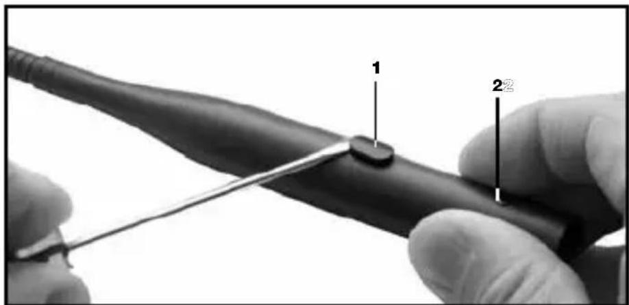
- Use a screwdriver to lever the ON/OFF button (1) out of the shell.
- Unscrew the fixing screw (2) CCW.
- Touch a bare, grounded metal part to discharge any static charge that may have built up on your body. (Electrostatic charges may damage electronic circuits.)
- Pull the circuit board out of the shell WITH EXTRA CARE.
4.1 Capsule Modules
Important:
4.2GN15/30/50ESP InstallationModules
4.2.1ON/OFFKey, LEDRing,Bass Cut
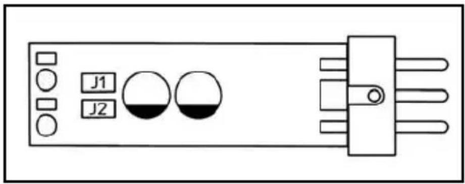
Fig. 1: Opening the DPA-P.
Refer to fig. 1.
Fig. 2: DPA-P jumpers and pinout (factory setting shown).
Refer to fig. 2.
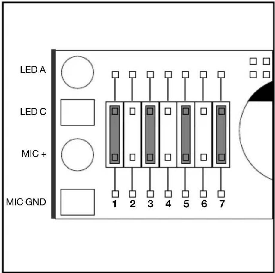
- At the factory, jumpers have been placed in positions 1, 3, 5, and 7:
- On powering up, the microphone will be muted and the LED ring will be dark.
- To open the microphone, press the ON/OFF key. The LED ring will be lit to indicate the microphone is open.
- To mute the microphone, press the ON/OFF key again. The LED ring will go out.
Positions 1 and 7 set the following functions:
Table 2: LED Ring and Bass Cut.
| Position Jumper in place No jumper | ||
| 1 Flat frequency response Bass rolloff: | -6 dB below 200 Hz | |
| 7 Mic on/off -> LED on/off LED off | ||
Note:
- Positions 1 and 7 will not affect the function of the ON/OFF key.
Positions 2 through 6 set the following functions:
| ON/OFF Key Functions Jumper Configurations | ||
| Microphone ON/OFF | Microphone OFF on system power-up | 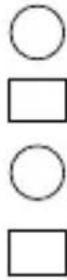 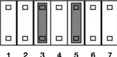 |
| Microphone ON on system power-up | 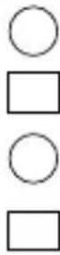 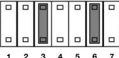 | |
| Push-to-mute | 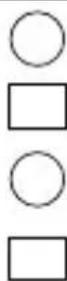 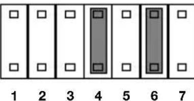 | |
| Push-to-talk | 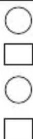 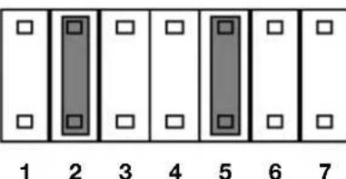 | |
| Microphone permanently ON. Key disabled. |  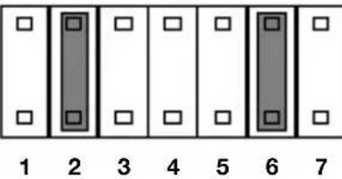 | |
Table 2a: ON/OFF Key
4 Installation and Connection
Important:
- Positions, 2, 3, 4: Be sure to place a jumper at one (but no more than one) of these three positions. If you place no jumper at any of these positions, pushing the ON/OFF button will have no effect.
- Positions 5, 6: Make sure there is a jumper placed at one of these positions at all times. With jumpers at both or none of these positions, the microphone status on power-up will be undefined.
- Never place two jumpers at positions 6 and 2 or 5 and 4 at the same time. This would effectively deactivate the ON/OFF button.
- Do not use any jumper configurations other than those given in Table 2a. Other configurations may cause malfunction.
- Push the circuit board into the shell. To make the circuit board slide more easily into the shell, turn the circuit board two or three times completely about its longitudinal axis as you push the circuit board in.
- Push the ON/OFF button into the opening in the shell to the point that the button clicks into place and tighten the fixing screw.
1 22
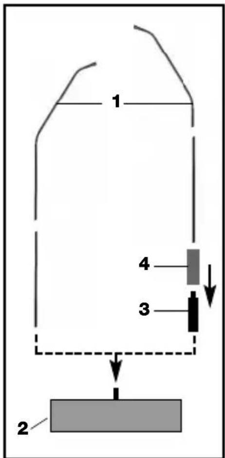
Fig. 3: Inserting the circuit board into the barrel.
Important: Refer to fig. 3.
- To prevent the circuit board from getting caught inside the barrel, make absolutely sure that the connecting wires (1) will not lie on top of the jumpers (2). You can double-check on that through the opening for the ON/OFF key as you push the circuit board home.
4 Installation and Connection
- Use the supplied PS 3 F-Lock panel mount socket to install the Installation Module in a tabletop or an optional SA 60 stand adapter to mount the Installation Module on a floor or table stand.
- For even better vibrational noise rejection, you can fix the Installation Module to the tabletop with an optional H 500 (see fig. 14) or H 600 + A 608 shock mount (see figs. 15 and 16).
- Use a shielded cable to connect the Installation Module to a microphone input with phantom power.
- If the phantom power on your mixing console is switchable, switch the phantom power on. (Refer to the instruction manual for your mixing console.) The Capsule Module and the LED ring will be powered from the phantom supply.
4.2.2 Installation and Connection
Note:
4 Installation and Connection
4.3GN15/30/50E Installation Modules 4.3.1 LEDRing
The LED rings on the GN 15/30/50 E operate off phantom power.
If you connected the microphone correctly, the LED will be lit at moderate intensity as soon as you switch the system and phantom power on. This indicates that the system is correctly wired and ready to operate but NOT that the microphone channel is open.
4.3.2 BassCut, Installation, Connection
Fig. 4: DPA circuit board
The DPA phantom power adapter provides a 6-dB/octave bass cut filter below 200 Hz to reduce low-frequency noise.
- Activating the Bass Cut Refer to fig. 4.
- Before grasping the circuit board, touch a bare, grounded metal part to discharge any static charge that may have built up on your body. (Electrostatic charges may damage electronic circuits.)
- Remove jumper J1 from the circuit board of the phantom power adapter.
• Installation and Connection
• Refer to Section 4.2.2.
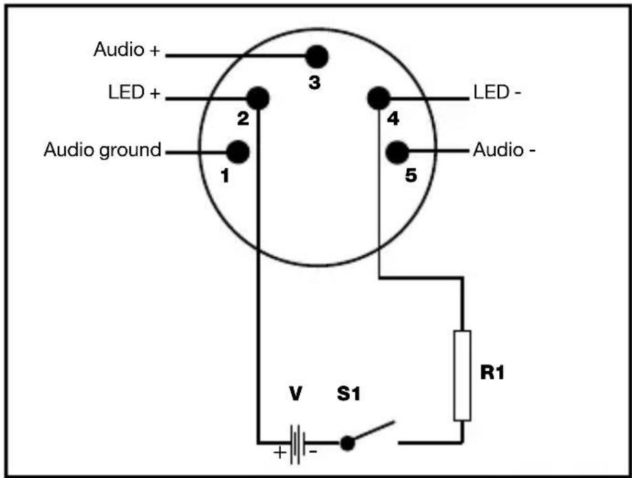
Pins 2 and 4 on the 5-pin XLR connector are available for powering the LED ring from an external source.
The specifications of resistor R1 depend on the available powering voltage V:
| V R1 Max. Power |
| 6 V 390 Ω0.1 W |
| 12 V 1000 Ω0.25 W |
| 24 V 2200 Ω0.25 W |
| 48 V 4700 Ω0.5 W |
Refer to Sections 4.2.2 and 4.3.2.
The LED rings on the GN 15/30/50 Installation Modules will be powered from the phantom supply. (See also Section 4.3.1.)
To obtain an open channel indication, the installation technician may connect the LED ring to an external power source. In this mode, the LED ring will light much more brightly to draw the required attention to the open microphone.
4.4GN15/30/50E 5PINInstallation Modules 4.4.1LEDRing
Fig. 5: LED ring external powering.
Refer to fig. 5.
Table 3: Electrical values for external powering of LED ring
4.4.2BassCut, Installation, Connection
4.5GN15/30 /50 Installation Modules
4.5.1 MICOPEN Indication

4 Installation and Connection
- Unsolder the black wire (LED +) and the outer shield (LED -) from the DPA phantom power adapter.
- Connect the black wire (LED +) and the outer shield (LED -) to a voltage source with an output voltage as per Table 4:
Table 4: Electrical values for external powering of LED ring
| Voltage Req'd resistor Max. power |
| 6 V 390 Ω0.1 W |
| 12 V 1k Ω0.25 W |
| 24 V 2.2 kΩ0.25 W |
| 48 V 4.7 kΩ0.5 W |
4.5.2 Tabletop Installation, Connection
- Drill an 11-mm (7/16") hole through the tabletop.
- Thread the connecting cable of the Installation Module through the opening and the supplied fixing screw.
- Screw the fixing screw into the Installation Module from below to fix the Installation Module in place.
Note:
- For even better vibrational noise rejection, you can fix the Installation Module to the tabletop with an optional H 600 + A 608 shock mount (see figs. 15 and 16).
•Audio Connection
- Plug the cable of the DPA phantom power adapter into the female mini XLR connector on the connecting cable of the Installation Module.
- Use a shielded cable to connect the DPA phantom power adapter to a microphone input with phantom power.
- If the phantom power on your mixing console is switchable, switch the phantom power on. (Refer to the instruction manual for your mixing console.) The Capsule Module and the LED ring will be powered from the phantom supply.
- Connectingtoa BodypackTrans- mitter
You may also connect the GN 15, GN 30, and GN 50 installation modules to a PT 40, PT 400, or PT 4000 body-pack transmitter from AKG. All you need to do is change the wiring of the mini XLR connector as shown in fig. 6 on page 35:
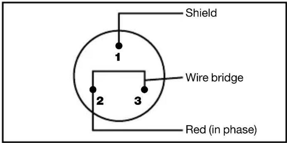
Pin 1: shield Black wire: unused
Pin 2: red wire (in phase) Outer shield: unused
Pin 3: bridge to pin 2
The LED rings on the GN 30/50 Minijack Installation Modules will be powered from the phantom supply. (See also Section 4.3.1.)
To obtain an open channel indication, the installation technician may connect the LED ring to an external power source. In this mode, the LED ring will light much more brightly to draw the required attention to the open microphone.
-
Unsolder the black wire (LED +) and the outer shield (LED -) from the HSC mounting flange and insulate the bare ends of the two wires.
-
Solder to the two contacts on the HSC that are now unused a two-conductor cable for powering the LED ring.
• To activate the bass cut, refer to Section 4.3.2.
- Drill a hole 40 to 42 mm (1.6 to 1.7 in.) in diameter into the tabletop.
- Use the supplied screws to fix the mounting flange in the hole.
- Use the supplied pipe clip to fix the phantom power adapter to the underside of the table.
- Use a shielded cable to connect the DPA phantom power adapter to a microphone input with phantom power.
Fig. 6: Connector pinout for connecting to bodypacks
4.6GN30/50Mini-jack
4.6.1 LEDRing, BassCut
Refer to fig. 25 on page 126.
4.6.2 Installation and Connection
Refer to fig. 25 on page 126.
4 Installation and Connection
- If the phantom power on your mixing console is switchable, switch the phantom power on. (Refer to the instruction manual for your mixing console.)
- External powering only: Connect the feeder cable for the LED ring to a suitable voltage source.
- Insert the jack plug on the gooseneck into the mini jack on the mounting flange and screw the gooseneck down.
4.7GN155SETIn-stallationModule
• To activate bass cut, refer to Section 4.3.2.
• For external powering of LED ring, refer to Section 4.5.1.
Refer to fig. 7 (left).
4.7.1 Gooseneck Extension
Refer to fig. 7 (right).
Fig. 7: GN 155 SET.
flowchart
graph TD
    A["1"] --> B["2"]
    B --> C["3"]
    C --> D["4"]
    D --> A
- Screw the desired Capsule Module onto the Installation Module (1) CW.
- Screw the Installation Module (1) onto the supplied floor stand (2) CW.
-
Connect the DPA phantom power adapter to a microphone input with phantom power.
-
Screw the desired Capsule Module onto the Installation Module (1) CW.
- Screw the extension stub (3) onto the supplied floor stand (2) CW.
-
Slide the protective sheath (4) over the extension stub (3).
-
Screw the Installation Module (1) onto the extension stub (3) CW.
4.8HM1000 HangingModule
- Prior to installing the HM 1000, straighten the cable by carefully pulling it through your fingers. Make sure not to buckle or twist the cable.
- Fasten a hook to the ceiling, use an existing hook, or stretch a line across the hall.
-
Pass the cable through the hook or over the line so that it will hang at the desired height.
-
Fix the cable in place with electrician's tape.
- Do not tie a knot into the cable to hang it on the hook.
Important:
natural_image
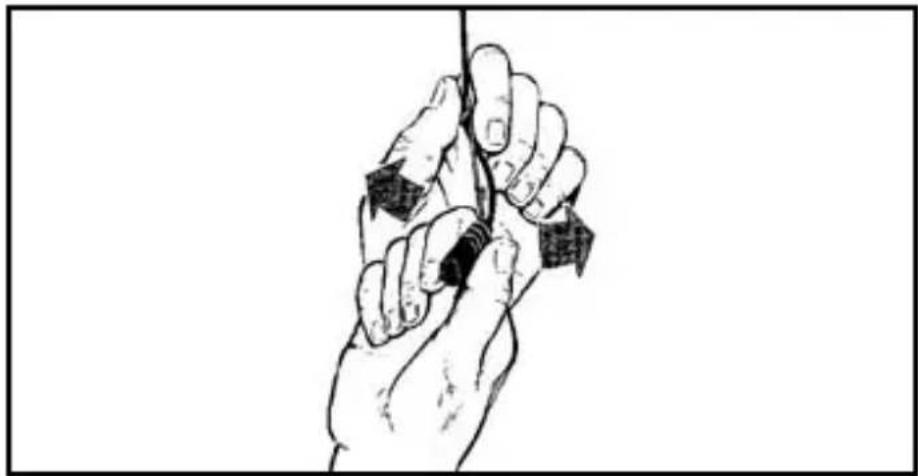
Line drawing of a hand gripping a vertical pole with arrows indicating force or movement (no text or symbols)- Hold the cable with one hand and turn the microphone carefully into the desired position.
Fig. 8: Aligning the microphone.
• To activate the bass cut, refer to Section 4.3.2.
- To power the LED ring from an external source, refer to Section 4.5.1.
Refer to fig. 8.
To keep the microphone steady even in a draft,
- Stretch a suitable length of fishing line horizontally across the room, passing the fishing line through the eye on the HM 1000.
- Fix the fishing line to two opposite walls so as to create just enough downward pull to steady the microphone laterally.
4.8.1 Steadying themicrophone
4 Installation and Connection
4.8.2Applications
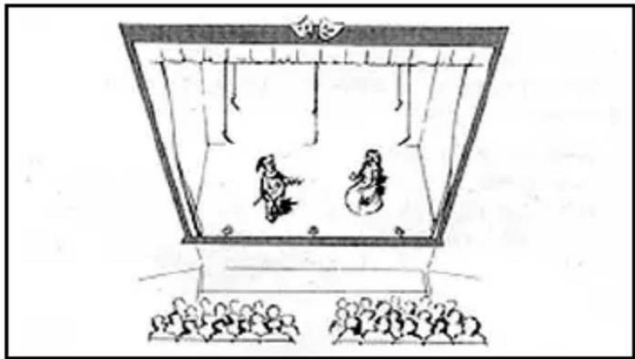
Fig. 9: Theater stage miking
natural_image
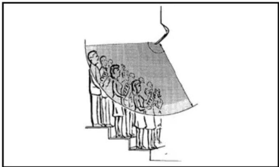
Illustration of a traditional Chinese opera scene with two performers on stage and audience seated below (no text or symbols)Fig. 10: Miking up a choir
natural_image
Illustration of a group of people standing on steps under a curved structure, possibly depicting a stage or presentation (no text or symbols present)4.8.3Audio Connection
Refer to section 4.5.2, Audio Connection
4.9GN15HT InstallationModule
Also read the instruction manual of the HT 4000 hand-held transmitter!
LED ring:
- Screw the desired Capsule Module onto the GN 15 HT Installation Module CW.
- Screw the Installation Module onto the HT 4000 hand-held transmitter CW.
- Use the SA 63 stand adapter supplied with the transmitter to mount the transmitter on an (optional) ST 45 table stand.
- Switch the transmitter ON. The LED ring on the Installation Module will illuminate to indicate the transmitter is ON.
4 Installation and Connection

- The LED ring will remain lit even if you press the MUTE button on the transmitter!
Remember that the LED ring does NOT necessarily indicate that the microphone is open and will not extinguish unless you switch the transmitter OFF.
- Of course, you may also use the microphone handheld, e.g., for questions from the audience.
The GN 30 OC Installation Modules has been designed for 1.5 V to 10 V a-b powering. The unterminated cable provides the following connections:
Red: microphone (hot), supply voltage +
Shield: Microphone (ground), supply voltage -
Black: LED +
Outer shield: LED -
- Connect the microphone wires to a microphone input with a-b powering.
- Connect the black wire (LED +) and the outer screen (LED -) to a voltage source with an output voltage as per Table 4 on page 30.
• GN 15/30/50 ESP: Referring to fig. 2 and Table 2 on page 28, remove the jumper from position 7.
• GN 15/30/50, GN 15/30/50 E, GN 30/50 Minijack, GN 155 SET, HM 1000: Referring to fig. 4 on page 32, remove jumper J2.
- GN 30 OC: Disconnect the LED feeder cable from the voltage source.
The unlit LED ring is nearly invisible because its color matches that of the case.
Important:
Note:
4.10GN30OC Installation Module
4.11 Defeating the LEDRing
5 Specifications
| Installation Module w/ CK 31 CK 32 CK 33 | |||
| Type Pre-polarized condenser microphone | |||
| Polar pattern Cardioid Omni Hypercardioid | |||
| Frequency range 50-20,000 Hz 20-20,000 Hz | 50-20,000 Hz | ||
| Sensitivity 20 mV/Pa 14 mV/Pa 20 mV/Pa -34 dBV* -37 | dBV* -34 dBV* | ||
| Electrical impedance | <600 Ω | <600 Ω | <600 Ω |
| Rated load impedance | >2000 Ω | >2000 Ω | >2000 Ω |
| Power requirement | 9-52 V phantom power to IEC 61938 -Requires DPA-P or DPA adapter (integrated in GN** and HM 1000 Installation Modules) | ||
| Size (dia. x length) | 13 x 25 mm(0.5 x 0.95 in.) | 13 x 25 mm(0.5 x 0.95 in.) | 13 x 25 mm(0.5. x 0.95 in.) |
| Connector** | XLR-3 or XLR-5 | XLR-3 or XLR-5 | XLR-3 or XLR-5 |
| Installation Module w/ CK 47 CK 80 | ||
| Type Pre-polarized condenser microphone | ||
| Polar pattern Hypercardioid | Hypercardioid | |
| Frequency range 20-20,000 Hz | 60-15,000 Hz | |
| Sensitivity 16.5 mV/Pa | 30 mV/Pa -35.5 dBV^* | -30 dBV^* |
| Electrical impedance | <600 Ω | <600 Ω |
| Rated load impedance | >2000 Ω | >2000 Ω |
| Power requirement | 9-52 V phantom power to IEC 61938 - Requires DPA-P or DPA adapter (integrated in GN** and HM 1000 Installation Modules) | |
| Size (dia. x length) | 13 x 154 mm(0.5 x 5.85 in.) | 13 x 128 mm(0.5 x 4.86 in.) |
| Connector** | XLR-3 or XLR-5 | XLR-3 or XLR-5 |
* Re 1 V/Pa
** Except GN 30 OC
This product conforms to the standards listed in the Declaration of Conformity. To order a free copy of the Declaration of Conformity, visit http://www.akg.com or contact sales@akg.com.
line
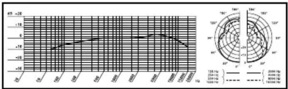
| Time (s) | Angle (°) | Value | |----------|-----------|-------| | 0 | 150 | -10 | | 30 | 160 | -8 | | 60 | 170 | -6 | | 90 | 180 | -4 | | 120 | 190 | -2 | | 150 | 200 | 0 | | 180 | 210 | 2 | | 210 | 220 | 4 | | 240 | 230 | 6 | | 270 | 240 | 8 | | 300 | 250 | 10 | | 330 | 260 | 12 | | 360 | 270 | 14 | | 390 | 280 | 16 | | 420 | 290 | 18 | | 450 | 300 | 20 | | 480 | 310 | 22 | | 510 | 320 | 24 | | 540 | 330 | 26 | | 570 | 340 | 28 | | 600 | 350 | 30 | | 630 | 360 | 32 | | 660 | 370 | 34 | | 690 | 380 | 36 | | 720 | 390 | 38 | | 750 | 400 | 40 | | 780 | 410 | 42 | | 810 | 420 | 44 | | 840 | 430 | 46 | | 870 | 440 | 48 | | 900 | 450 | 50 | | 930 | 460 | 52 | | 960 | 470 | 54 | | 990 | 480 | 56 | | 1020 | 490 | 58 | | 1050 | 500 | 60 | | 1080 | 510 | 62 | | 1110 | 520 | 64 | | 1140 | 530 | 66 | | 1170 | 540 | 68 | | 1200 | 550 | 70 | | | | +15 | | | | +16 | | | | +17 | | | | +18 | | | | +19 | | | | +20 | | | | +21 | | | | +22 | | | | +23 | | | | +24 | | | | +25 | | | | +26 | | | | +27 | | | | +28 | | | | +29 | | | | +30 | | | | +31 | | | | +32 | | | | +33 | | | | +34 | | | | +35 | | | | +36 | | | | +37 | | | | +38 | | | | +39 | | | | +40 | | | | +41 | | | | +42 | | | | +43 | | | | +44 | | | | +45 | | | | +46 | | | | +47 | | | | +48 | | | | +49 | | | | +50 | | | | +51 | | | | +52 | | | | +53 | | | | +54 | | | | +55 | | | | +56 | | | | +57 | | | | +58 | | | | +59 | | | | +60 | | | | +61 | | | | +62 | | | | +63 | | | | +64 | | | | +65 | | | | +66 | | | | +67 | | | | +68 | | | | +69 | | | | +70 | | | | +71 | | | | +72 | | | | +73 | | | | +74 | | | | +75 | | | | +76 | | | | +77 | | | | +78 | | | | +79 | | | | +80 | | | | +81 | | | | +82 | | | | +83 | | | | +84 | | | | +85 | | | | +86 | | | | +87 | | | | +88 | | | | +89 | | | | +90 | | | | +91 | | | | +92 | | | | +93 | | | | +94 | | | | +95 | | | | +96 | | | | +97 | | | | +98 | | | | +99 | | | | +100 | The chart displays the angle values (in degrees) of a single variable (P = -15 to -19) over time (seconds). The data is presented in a grid format with 'Time' as the index and 'Value' as the y-axis. The angle values are calculated using the formula 'P = -15'. The chart is divided into two sections: 'Before' (left) and 'After' (right), each divided into four quadrants (e.g., 'P = -15', 'P = -16', 'P = -17', 'P = -18', and 'P = -19'). The angle values are calculated using the formula 'P = -15', 'P = -16', 'P = -17', 'P = -18', and 'P = -19' respectively. The angle values are calculated using the formula 'P = -15', 'P = -16', 'P = -17', and 'P = -18' respectively. The angle values are calculated using the formula 'P = -15', 'P = -16', 'P = -17', and 'P = -18' respectively. The angle values are calculated using the formula 'P = -15', 'P = -16', 'P = -17', and 'P = -18' respectively. The angle values are calculated using the formula 'P = -15', 'P =-16', 'P =-17', and 'P =-18' respectively. The angle values are calculated using the formula 'P =-15', 'P =-16', 'P =-17', and 'P =-18' respectively. The angle values are calculated using the formula 'P =-15', 'P =-16', 'P =-17', and 'P =-18' respectively. The angle values are calculated using the formula 'P =-15', 'P =-16', 'P =-17', and 'P = -18'.CK31Frequency Response and PolarDiagrams
line
| Frequency (Hz) | Value | | -------------- | ----- | | 120 | +20 | | 300 | -10 | | 600 | -15 | | 900 | -20 | | 1200 | -25 | | 1500 | -30 | | 1800 | -35 |CK32Frequency Response and PolarDiagrams
line
| Frequency (Hz) | Amplitude (mA) | | -------------- | -------------- | | 125 | -10 | | 250 | -10 | | 300 | -10 | | 400 | -10 | | 500 | -10 | | 600 | -10 | | 700 | -10 | | 800 | -10 | | 900 | -10 | | 1000 | -10 | | 1100 | -10 | | 1200 | -10 | | 1300 | -10 | | 1400 | -10 | | 1500 | -10 | | 1600 | -10 | | 1700 | -10 | | 1800 | -10 | | 1900 | -10 | | 2000 | -10 |CK33Frequency Response and PolarDiagrams
line
| Time (s) | Value | |----------|-------| | 0 | -10 | | 5 | -15 | | 10 | -20 | | 15 | -25 | | 20 | -30 | | 25 | -35 | | 30 | -40 | | 35 | -45 | | 40 | -50 | | 45 | -55 | | 50 | -60 | | 55 | -65 | | 60 | -70 | | 65 | -75 | | 70 | -80 | | 75 | -85 | | 80 | -90 | | 85 | -95 | | 90 | -100 | | 95 | -105 | | 100 | -110 | | 105 | -115 | | 110 | -120 | | 115 | -125 | | 120 | -130 |CK47Frequency Response and PolarDiagrams
line
| Frequency (Hz) | Value | |---|---| | 0 | -15 | | 10 | -12 | | 20 | -10 | | 30 | -8 | | 40 | -6 | | 50 | -4 | | 60 | -2 | | 70 | 0 | | 80 | 2 | | 90 | 4 | | 100 | 6 | | 110 | 8 | | 120 | 10 | | 130 | 12 | | 140 | 14 | | 150 | 16 | | 160 | 18 | | 170 | 20 | | 180 | 22 | | 190 | 24 | | 200 | 26 | | 210 | 28 | | 220 | 30 | | 230 | 32 | | 240 | 34 | | 250 | 36 | | 260 | 38 | | 270 | 40 | | 280 | 42 | | 290 | 44 | | 300 | 46 | | 310 | 48 | | 320 | 50 | | 330 | 52 | | 340 | 54 | | 350 | 56 | | 360 | 58 | | 370 | 60 | | 380 | 62 | | 390 | 64 | | 400 | 66 | | 410 | 68 | | 420 | 70 | | 430 | 72 | | 440 | 74 | | 450 | 76 | | 460 | 78 | | 470 | 80 | | 480 | 82 | | 490 | 84 | | 500 | 86 | | 510 | 88 | | 520 | 90 | | 530 | 92 | | 540 | 94 | | 550 | 96 | | 560 | 98 | | 570 | 100 | | 580 | 102 | | 590 | 104 | | 600 | 106 | | 610 | 108 | | 620 | 110 | | 630 | 112 | | 640 | 114 | | 650 | 116 | | 660 | 118 | | 670 | 120 | | 680 | 122 | | 690 | 124 | | 700 | 126 | | 710 | 128 | | 720 | 130 | | 730 | 132 | | 740 | 134 | | 750 | 136 | | 760 | 138 | | 770 | 140 | | 780 | 142 | | 790 | 144 | | 800 | 146 | | 810 | 148 | | 820 | 150 | | 830 | 152 | | 840 | 154 | | 850 | 156 | | 860 | 158 | | 870 | 160 | | 880 | 162 | | 890 | 164 | | 900 | 166 | | 910 | 168 | | 920 | 170 | | 930 | 172 | | 940 | 174 | | 950 | 176 | | 960 | 178 | | 970 | 180 | | 980 | 182 | | 990 | 184 | | 1000 | 186 | | Note: The frequency values are estimated based on the chart's visual scale and the angle of the data points. The angle values are calculated based on the number of degrees. The chart is divided into two sections: 'Top section' (lower side) and 'Bottom section' (upper side).CK80Frequency Response and PolarDiagrams

Table des matières
Page
4.2.2 Montageet raccordement
Remarque:

4 Montage et raccordement
4.3Modulesde montage GN15/30/50E 4.3.1Anneau lumineux
4.4Modulesde
montage
GN15/30/50E5PIN
Fig. 5: Alimentation externe de l'anneau lumineux
Voir Fig. 5.
4.6.2 Montage, raccordement
Voir Fig. 25 page 126.
natural_image
Line drawing of a hand gripping a vertical pole with directional arrows indicating movement (no text or symbols)Fig. 8: Orientation du microphone
natural_image
Illustration of a traditional Chinese opera scene with two performers and a seated audience (no text or symbols)natural_image
Illustration of a group of people standing on steps under a curved platform, viewed from above (no text or symbols present)4.8.3 Raccordement audio
4.9Modulede montageGN15HT
line
| Angle (°) | Value | |---|---| | 120 | -15 | | 130 | -14 | | 140 | -13 | | 150 | -12 | | 160 | -11 | | 170 | -10 | | 180 | -9 | | 190 | -8 | | 200 | -7 | | 210 | -6 | | 220 | -5 | | 230 | -4 | | 240 | -3 | | 250 | -2 | | 260 | -1 | | 270 | 0 | | 280 | 1 | | 290 | 2 | | 300 | 3 | | 310 | 4 | | 320 | 5 | | 330 | 6 | | 340 | 7 | | 350 | 8 | | 360 | 9 | | 370 | 10 | | 380 | 11 | | 390 | 12 | | 400 | 13 | | 410 | 14 | | 420 | 15 | | 430 | 16 | | 440 | 17 | | 450 | 18 | | 460 | 19 | | 470 | 20 | | 480 | 21 | | 490 | 22 | | 500 | 23 | | 510 | 24 | | 520 | 25 | | 530 | 26 | | 540 | 27 | | 550 | 28 | | 560 | 29 | | 570 | 30 | | 580 | 31 | | 590 | 32 | | 600 | 33 | | 610 | 34 | | 620 | 35 | | 630 | 36 | | 640 | 37 | | 650 | 38 | | 660 | 39 | | 670 | 40 | | 680 | 41 | | 690 | 42 | | 700 | 43 | | 710 | 44 | | 720 | 45 | | 730 | 46 | | 740 | 47 | | 750 | 48 | | 760 | 49 | | 770 | 50 | | 780 | 51 | | 790 | 52 | | 800 | 53 | | 810 | 54 | | 820 | 55 | | 830 | 56 | | 840 | 57 | | 850 | 58 | | 860 | 59 | | 870 | 60 | | 880 | 61 | | 890 | 62 | | 900 | 63 | | 910 | 64 | | 920 | 65 | | 930 | 66 | | 940 | 67 | | 950 | 68 | | 960 | 69 | | 970 | 70 | | 980 | 71 | | 990 | 72 | |1000+ | -18 | The chart displays a single data series with 'Value' on the Y-axis and 'Angle' on the X-axis. The data series are labeled with 'Hα' as the index of the chart. The 'Hα' axis is labeled '120 Hα', and the 'Hβ' axis is labeled '25 Hβ'. The 'Hγ' axis is labeled '35 Hγ', and the 'Hβ' axis is labeled '45 Hβ'. The 'Hα' axis is labeled '55 Hα', and the 'Hβ' axis is labeled '65 Hβ'. The 'Hγ' axis is labeled '75 Hγ', and the 'Hβ' axis is labeled '85 Hβ'. The data points are plotted as solid lines connecting the lines to the right side of the chart. The chart is divided into four quadrants by selecting the angles in the top-right quadrant. The label 'Hα' appears twice: '120 Hα' and '25 Hα', indicating a specific measurement point for that region. The label 'Hβ' appears twice: '35 Hβ' and '45 Hβ'.Importante:
Vedi fig. 3.
natural_image
Line drawing of a hand gripping a vertical object with arrows indicating motion (no text or symbols)natural_image
Illustration of a traditional Chinese opera scene with two performers and a large audience (no text or symbols)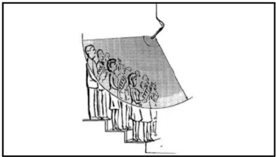
natural_image
Illustration of a group of people standing on steps under a curved structure (no text or symbols)line
| Frequency (Hz) | Voltage (mA) | Current (V) | | -------------- | ----------- | ----------- | | 0 | -15 | 3000 | | 10 | -12 | 6000 | | 20 | -10 | 7000 | | 30 | -8 | 6500 | | 40 | -6 | 6000 | | 50 | -4 | 5500 | | 60 | -2 | 5000 | | 70 | 0 | 4500 | | 80 | 2 | 4000 | | 90 | 4 | 3500 | | 100 | 6 | 3000 | | 110 | 8 | 2500 | | 120 | 10 | 2000 | | 130 | 12 | 1500 | | 140 | 14 | 1000 | | 150 | 16 | 500 | | 160 | 18 | 250 | | 170 | 20 | 100 | | 180 | 22 | 50 | | 190 | 24 | 25 | | 200 | 26 | 10 | | 210 | 28 | 5 | | 220 | 30 | 2 | | 230 | 32 | 1 | | 240 | 34 | 0.5 | | 250 | 36 | 0.2 | | 260 | 38 | 0.1 | | 270 | 40 | 0.05 | | 280 | 42 | 0.02 | | 290 | 44 | 0.01 | | 300 | 46 | 0.005 | | 310 | 48 | 0.002 | | 320 | 50 | 0.001 | | 330 | 52 | 0.0005 | | 340 | 54 | 0.0002 | | 350 | 56 | 0.0001 | | 360 | 58 | 0.00005 | | 370 | 60 | 0.00002 | | 380 | 62 | 0.00001 | | 390 | 64 | 0.000005 | | 400 | 66 | 0.000002 | | 410 | 68 | 0.000001 | | 420 | 70 | 0.0000005 | | 430 | 72 | 0.0000002 | | 440 | 74 | 0.0000001 | | 450 | 76 | 0.00000005 | | 460 | 78 | 0.00000002 | | 470 | 80 | 0.00000001 | | 480 | 82 | 0.000000005 | | 490 | 84 | 0.000000002 | | 500 | 86 | 0.000000001 | | Note: The frequency values are estimated based on the current value of the chart. The current value is calculated as the sum of the current and voltage values for each frequency point. The current value is calculated as the sum of the current and voltage values for each frequency point. The current value is calculated as the sum of the current and voltage values for each frequency point.Figs. 11 a 25....122
natural_image
Line drawing of a hand gripping a vertical object with arrows indicating motion (no text or symbols)natural_image
Illustration of a traditional Chinese opera scene with two performers and a large audience (no text or symbols)Fig. 10: Toma de coros
natural_image
Illustration of a group of people standing on steps under a curved structure (no text or symbols)line
| Time (s) | Value | | -------- | ----- | | 0 | -10 | | 10 | -5 | | 20 | 0 | | 30 | 5 | | 40 | 10 | | 50 | 15 | | 60 | 20 | | 70 | 25 | | 80 | 30 | | 90 | 35 | | 100 | 40 | | 110 | 45 | | 120 | 50 | | 130 | 55 | | 140 | 60 | | 150 | 65 | | 160 | 70 | | 170 | 75 | | 180 | 80 | | 190 | 85 | | 200 | 90 | | 210 | 95 | | 220 | 100 | | 230 | 105 | | 240 | 110 | | 250 | 115 | | 260 | 120 | | 270 | 125 | | 280 | 130 | | 290 | 135 | | 300 | 140 | | 310 | 145 | | 320 | 150 | | 330 | 155 | | 340 | 160 | | 350 | 165 | | 360 | 170 | | 370 | 175 | | 380 | 180 | | 390 | 185 | | 400 | 190 | | 410 | 195 | | 420 | 200 | | 430 | 205 | | 440 | 210 | | 450 | 215 | | 460 | 220 | | 470 | 225 | | 480 | 230 | | 490 | 235 | | 500 | 240 | | 510 | 245 | | 520 | 250 | | 530 | 255 | | 540 | 260 | | 550 | 265 | | 560 | 270 | | 570 | 275 | | 580 | 280 | | 590 | 285 | | 600 | 290 | | 610 | 295 | | 620 | 300 | | 630 | 305 | | 640 | 310 | | 650 | 315 | | 660 | 320 | | 670 | 325 | | 680 | 330 | | 690 | 335 | | 700 | 340 | | 710 | 345 | | 720 | 350 | | 730 | 355 | | 740 | 360 | | 750 | 365 | | 760 | 370 | | 770 | 375 | | 780 | 380 | | 790 | 385 | | 800 | 390 | | 810 | 395 | | 820 | 400 | | 830 | 405 | | 840 | 410 | | 850 | 415 | | 860 | 420 | | 870 | 425 | | 880 | 430 | | 890 | 435 | | 900 | 440 | | 910 | 445 | | 920 | 450 | | 930 | 455 | | 940 | 460 | | 950 | 465 | | 960 | 470 | | 970 | 475 | | 980 | 480 | | 990 | 485 | | 1000 | 490 | | ... | ... | The chart displays two sets of data: the left set represents a line graph with values ranging from -18 to +48, and the right set represents a polar plot with values ranging from -2 to +2. The x-axis is labeled 'Time' (seconds) and the y-axis is labeled 'Value'. The legend indicates 'Time' (Hz) and 'Value' (Hz). The dashed lines represent 'Time' (Hz) and 'Value' (Hz). The solid line represents 'Value' (Hz). The dotted lines represent 'Time' (Hz) and 'Value' (Hz). The solid line represents 'Time' (Hz) and 'Value' (Hz). The dashed line represents 'Time' (Hz) and 'Value' (Hz). The solid line represents 'Time' (Hz). The dotted line represents 'Time' (Hz). The solid line represents 'Value' (Hz). The dashed line represents 'Value' (Hz). The dotted line represents 'Value' (Hz). The solid line represents 'Value' (Hz). The dashed line represents 'Value' (Hz). The dotted line represents 'Value' (Hz). The solid line represents 'Value' (Hz). The dashed line represents 'Value' (Hz). The dotted line represents 'Value' (Hz). The solid line represents 'Value' (Hz). The dashed line represents 'Value' (Hz). The dotted line represents 'Value' (Hz). The solid line represents 'Number of Hours'. The dashed line represents 'Number of Hours'.natural_image
Line drawing of a hand holding a rope with directional arrows indicating movement (no text or symbols)natural_image
Illustration of a traditional Chinese opera scene with two performers and audience (no text or symbols)natural_image
Illustration of a group of people standing on steps under a curved structure, possibly depicting a stage or architectural scene (no text or symbols present)natural_image
Close-up of a black circular mechanical flange with a metallic threaded component and four mounting holes (no text or symbols visible)
natural_image
Black plastic mechanical component with flange and bolted head (no text or symbols)Fig.13Fig.14
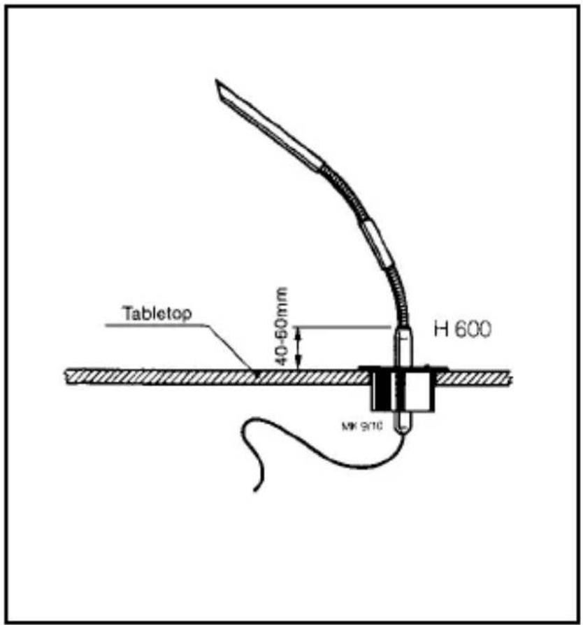
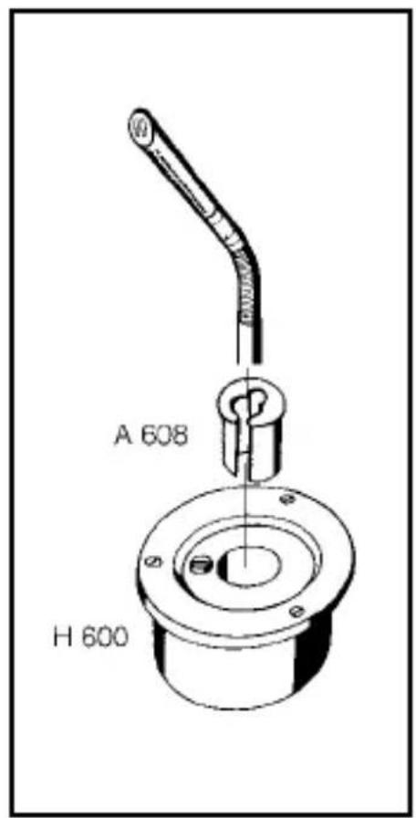
Fig.15Fig.16
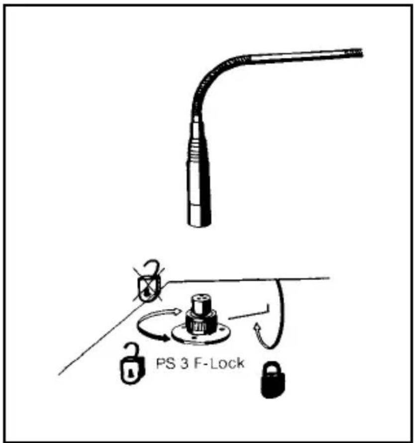
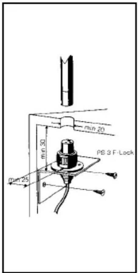
Fig.17 Fig.18
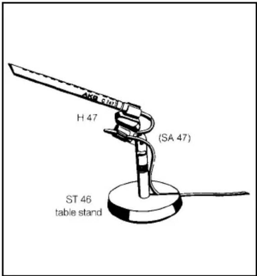

Fig.19Fig.20
Fig.21 Fig.22
Fig.23
Fig.24
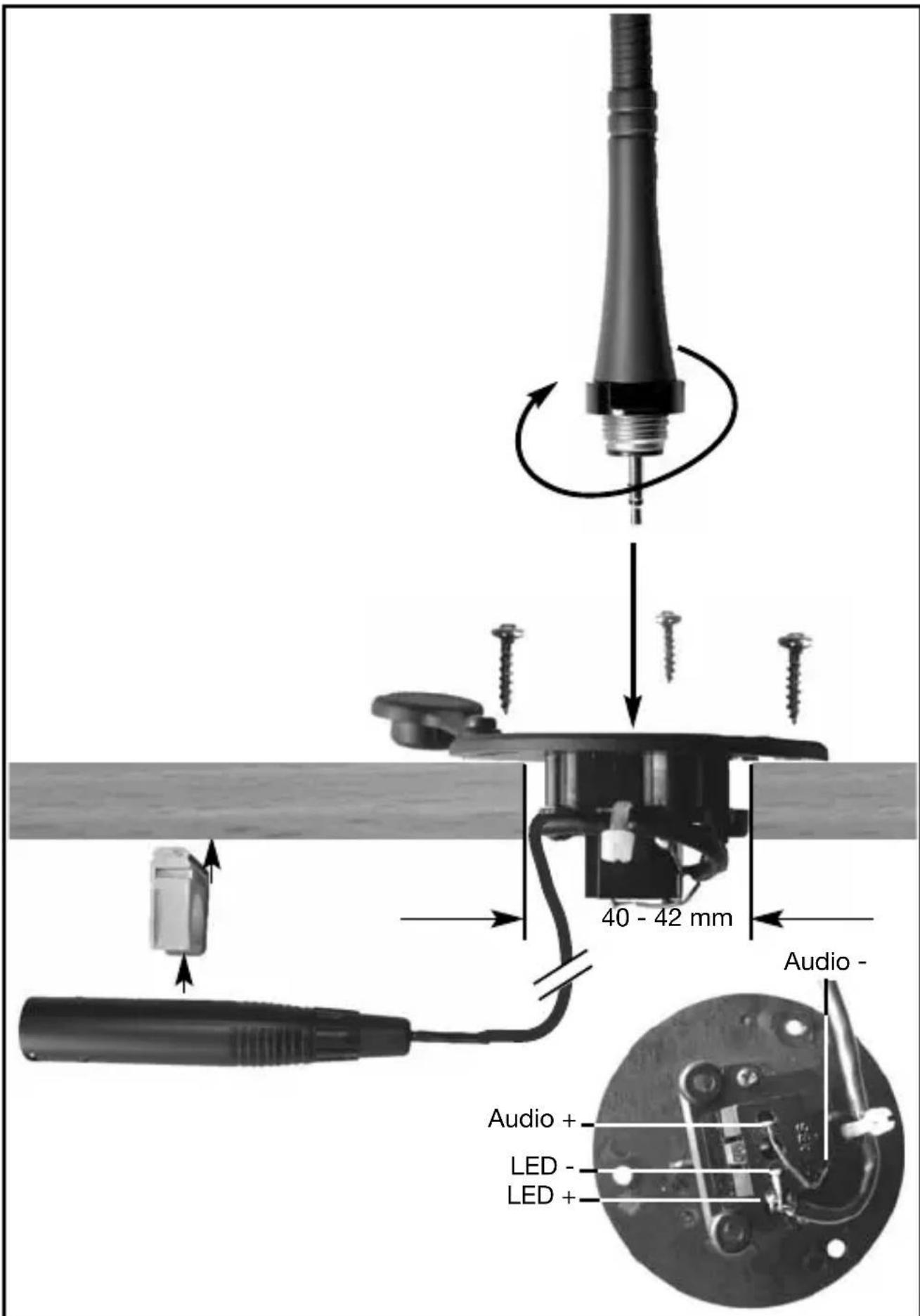
Fig.25
Mikrofone · Kopfhörer · Drahtlosmikrofone · Drahtloskopfhörer · Kopfsprechgarnituren · Akustische Komponenten Microphones · Headphones · Wireless Microphones · Wireless Headphones · Headsets · Electroacoustical Components Microphones · Casques HiFi · Microphones sans fil · Casques sans fil · Micros-casques · Composants acoustiques Microfoni · Cuffie HiFi · Microfoni senza filo · Cuffie senza filo · Cuffie-microfono · Componenti acustici Micrófonos · Auriculares · Micrófonos inalámbricos · Auriculares inalámbricos · Auriculares con micrófono · Componentes acústicos Microfones · Fones de ouvido · Microfones s/fios · Fones de ouvido s/fios · Microfones de cabeça · Componentes acústicos
AKG Acoustics GmbH
Lemböckgasse 21–25, A-1230 Vienna/AUSTRIA, phone: (+43-1) 86654-0*
e-mail: sales@akg.com
For other products and distributors worldwide visit www.akg.com


ROHS OK
H A Harman International Company
Technische Änderungen vorbehalten. Specifications subject to change without notice. Ces caractéristiques sont susceptibles de modifications. Ci riserviamo il diritto di effettuare modifiche tecniche. Nos reservamos el derecho de introducir modificaciones técnicas. Especificações sujeitas a mudanças sem aviso prévio.
Printed in Taiwan. 09/09/9100 U 12250


- Table of Contents
- Safety and Environment
- Description
- Introduction
- Capsule Modules
- 2.3W30 Windscreen
- Installation Modules
- LEDRing
- 2.5Optional Accessories
- Microphone Applications
- Installation and Connection
- Capsule Modules
- Important:
- 4.2GN15/30/50ESP InstallationModules
- 4.2.1ON/OFFKey, LEDRing,Bass Cut
- Note:
- Installation and Connection
- 4.3GN15/30/50E Installation Modules 4.3.1 LEDRing
- BassCut, Installation, Connection
- Tabletop Installation, Connection
- •Audio Connection
- - Connectingtoa BodypackTrans- mitter
- 4.6GN30/50Mini-jack
- LEDRing, BassCut
- Installation and Connection
- 4.7GN155SETIn-stallationModule
- Gooseneck Extension
- 4.8HM1000 HangingModule
- 4.8.2Applications
- 4.8.3Audio Connection
- 4.9GN15HT InstallationModule
- 4.10GN30OC Installation Module
- Defeating the LEDRing
- Specifications
- Table des matières
- Montageet raccordement
- Remarque:
- Montage et raccordement
- Montage, raccordement
- Raccordement audio
- 4.9Modulede montageGN15HT
- Importante:
- AKG Acoustics GmbH
Brand : AKG
Model : GN30E
Category : Microphone