
DHT800 - Microphone AKG - Free user manual and instructions
Find the device manual for free DHT800 AKG in PDF.

| Product type | Digital wireless microphone |
| Brand | AKG |
| Model | DHT800 |
| Carrier frequency range | Band 1: 548.1 – 697.9 MHz Band 2: 710.1 – 831.9 MHz (depending on country) |
| Switching bandwidth | ≤ 150 MHz (depending on country) |
| Transmit power | 10, 20, 30, 50 mW (max. ERP) adjustable via menu |
| Antenna | Integrated helical |
| Interchangeable microphone capsules | D5 WL1 (dynamic supercardioid), D7 WL1 (dynamic supercardioid), C5 WL1 (condenser cardioid) |
| Maximum sound pressure level | Up to 144 dB SPL (depending on capsule) |
| Audio input gain | 0 dB or +10 dB switchable |
| Power supply | 2 LR6 (AA) 1.5 V batteries or NiMH 1.2 V AA rechargeable batteries >2100 mAh |
| Battery life | Approx. 6.5 hours |
| Dimensions (without WL1 capsule) | 37 mm (⌀) x 170 mm (L) |
| Net weight (without capsule and batteries) | 129 g |
| Display | Alphanumeric with battery level indicator |
| Main functions | MUTE, infrared synchronization, 512-bit encryption, SILENT mode, power adjustment |
| Maintenance and cleaning | Clean with a soft damp cloth (not wet). Do not use solvents or abrasive detergents. |
| Safety | Use in a dry place. Do not open the device. Dispose of used batteries according to local regulations. |
| Spare parts and repairability | Maintenance operations are reserved for authorized professionals. Microphone capsules available as options. |
| Included accessories | SA63 stand adapter, W3004 windscreen, charging adapter for CU800/CU700, colored identification strips |
| Warranty | Manufacturer's warranty according to applicable terms. See manual for details. |
| Declaration of conformity | Available at www.akg.com |
Frequently Asked Questions - DHT800 AKG
User questions about DHT800 AKG
0 question about this device. Answer the ones you know or ask your own.
Ask a new question about this device
Download the instructions for your Microphone in PDF format for free! Find your manual DHT800 - AKG and take your electronic device back in hand. On this page are published all the documents necessary for the use of your device. DHT800 by AKG.
USER MANUAL DHT800 AKG
Read the manual before using the equipment!
MODE D'EMPLOI 117
DMS800
DIGITAL WIRELESS
MICROPHONE SYSTEM
Read the manual before using the equipment!
MODE D'EMPLOI 117
1.1 Purpose of the manual 63
1.2 Retention of the manual 63
1.3 Liability 63
1.4 Warranty 63
2 Package content 64
3 Safety and environment 66
3.1 Safety 66
3.2 Explanation of the symbols used 67
3.3 Correct use 67
3.4 Incorrect use 67
3.5 Environment 68
4 Declaration of Conformity 68
5 Equipment description 69
5.1 General description 69
5.2 Functions of the external MUTE switch (optional) 69
5.3 Technical data 69
5.4 DSR800: Description of the controls 72
5.5 DSR800: Description of the display elements 74
5.6 DPT800: Description of the controls 74
5.7 DPT800: Description of the display elements 75
5.8 DHT800: Description of the controls 75
5.9 DHT800: Description of the display elements 76
6 Commissioning 77
6.1 Insert batteries into the transmitter 77
6.2 Connecting the antennas 77
6.3 Position the receiver 78
6.4 Connecting the receiver to the mixing console/amplifier 79
6.4.1 Analog outputs 79
6.4.2 Digital output: Dante ^TM 79
6.4.3 Digital output: AES-EBU 80
6.5 Reposition the GROUND LIFT switch (optional) 80
6.6 Connecting the receiver to the power network 81
7 QUICK SETUP 82
8 Operating instructions 84
8.1 Setting the carrier frequency 84
8.1.1 Setting the transmitter to SILENT mode 84
8.1.2 Unlocking the receiver 84
8.2 Switch on MUTE LOCK 85
8.3 Programming the transmitter to the receiver settings 85
8.4 Carrying out a REHEARSAL 86
8.5 Selecting the country 86
8.6 Listening to the audio signal 87
9 Controls on the receiver 88
9.1 Functions of the SELECT wheel (5) 88
9.1.1 Functions in LOCK mode 88
9.1.2 Functions in SETUP mode 88
9.1.3 Possible functions in the main window 88
9.2 Functions of the CH1, CH2 (10, 12) buttons 89
9.2.1 Functions in LOCK mode 89
9.2.2 Functions in SETUP mode 89
9.3 Functions of the BACK button (4) 89
9.4 Functions of the DSP button (2) 89
9.5 Functions of the headphones
buttons CH1, CH2 (6) 90
12.5 REHEARSAL menu 101
12.6 UTILITY menu 102
10 Display of the receiver 91
10.1 Main window 91
10.2 Battery indicator 91
10.2.1 Audio level indicator (E) 91
10.2.2 MUTE indicator 92
10.2.3 Antenna indicator 92
10.3 Status and warning messages 92
10.3.1 Status and warning displays by urgency 93
10.4 Channel window 94
10.4.1 Opening the channel window 95
13 Menu structure of the transmitter 103
13.1 Preset mode 103
13.2 Frequency mode 103
13.3 Silent mode 104
14 Functional description 105
14.1 CHANNEL menu 105
15 Maintenance and cleaning 110
15.1 Maintenance 110
15.2 Cleaning 110
11 Display of the transmitter 96
11.1 Battery indicator 96
12 Menu structure of the receiver 97
12.1 QUICK SETUP menu 98
12.2 CHANNEL menu 99
12.3 AUDIO menu 100
12.4 ENVIR. menu SCAN 101
16 Troubleshooting 111
16.1 DSP profiles: Factory settings 114
17 DMS800: Controls 115
17.1 DSR800 115
17.2 DPT800 116
17.3 DHT800 116
| Publisher | AKG Acoustics GmbHLaxenburger Straße 2541230 WienAustriaTel: +43 (0)1 86654-0Fax: +43 (0)1 86654-8800sales@akg.com |
| Copyright | © 2015 AKG Acoustics GmbHAll rights reserved.The information contained in this manual, including any drawings and photos provided, are the intellectual property of AKG Acoustics GmbH.In accordance with copyright law, it is not permitted for this documentation or parts thereof to be reproduced or transmitted for any purpose in any form using any means, whether electronic or mechanical, by photocopying, recording or using information storage and information processing systems without the express, written consent of AKG Acoustics GmbH. Forwarding to third parties is not permitted. This manual should be returned to us on request. |
| Updates This manual may be modified without prior notice and does not represent any obligation on the part of AKG Acoustics GmbH. | |
| Version | 1.6 |
| Publication date | April 2016/EN |
1 General
1.1 Purpose of the manual
This manual is intended to enable you to:
• operate the equipment safely
- use the equipment correctly.
1.2 Retention of the manual
Print out this manual and keep it carefully or store it electronically at an easily accessible location.
Pass this manual on to subsequent owners.
This manual is an important part of the equipment.
Liability
1.3 Liability
AKG Acoustics GmbH accepts no liability, if:
- The equipment is used for purposes other than those described under correct usage.
- Damage is incurred due to incorrect operation
- Unauthorized or non-permitted modifications having been carried out.
- Damage due to out of date documentation.
Warranty
1.4 Warranty
AKG Acoustics GmbH accepts no liability for damage, if
- incorrect operation.
- Unauthorized or non-permitted modifications having been carried out.
- Damage due to out of date documentation.
2 Package content
Check that the package contains all the parts given below. If anything is missing, please contact your AKG dealer.
DSR800
DSR800
- 1 x DSR800 receiver
- 2 x BNC UHF antennas
- 2 x adapter cables for front antennas mounting 0110E01890
- 1 x mains cable conforming to EU standard
- 1 x mains cable conforming to US standard
DPT800
DPT800
- 1 x DPT800 bodypack transmitter
- 2 x LR6 batteries (size AA)
- 1 x MKG L instrument cable
DHT800
DHT800
• 1 x DHT800 handheld transmitter
- 2 x LR6 batteries (size AA)
- 1 x SA63 stand adapter
- 1 x W3004 – windscreen for D5 WL1, D7 WL1 and C5 WL1
- 1 x charging adapter for CU800 and CU700
- Colour marking tapes
Optional accessories
OPTIONAL ACCESSORIES
- CU800 and CU700 — charging unit for DPT800 and DHT800
• RMS4000 — external MUTE switch - Microphone heads D5 WL1, D7 WL1 and C5 WL1
- WLMA-US – adapter for Shure ^®1 microphone heads
• HUB4000 Q – network interface
Antenna
ANTENNA ACCESSORIES
- SRA2 W or SRA2 EW – passive directional antenna
- SRA2 B/W or SRA2 B/EW – active directional antenna
- RA4000 W or RA4000 EW – passive omnidirectional antenna
- RA4000 B/W or RA4000 B/EW – active omnidirectional antenna
- PS4000 W or APS4 – active antenna splitter
- AB4000 or AB4000 EW – antenna booster
- MK PS – antenna cable, 60 cm
- MKA5 – antenna cable, 5 m
- MKA20 – antenna cable, 20 m
- 0110E01890 – adapter cable for front antenna mounting

Other options and antenna accessories are available in the current AKG catalogue as a download from www.akg.com. Your dealer will be happy to advise.
3 Safety and environment
Safety
3.1 Safety
- Protect the equipment against
- direct sunlight
- the impact of significant dust and humidity
- rain
-
vibrations or knocks.
-
Do not spill any liquids on the equipment and do not allow any other objects to drop through the ventilation slits into the equipment.
- Do not place any containers filled with liquid on the equipment.
- The equipment must only be used in dry rooms.
- The equipment must only be opened, serviced and repaired by authorized personnel. The equipment contains no user-serviceable parts.
- Before connecting the equipment to power, check that the AC mains voltage stated on the integrated power adapter (DSR800) is identical to the AC mains voltage available where the equipment will be used.
- Only operate the equipment on a mains voltage between 100 and 240 V AC. Using adapters with different output voltage or current types may cause serious damage to the equipment.
- If any solid or liquid should get into the equipment, shut down the system immediately. Disconnect the power cable (DSR800) from the power outlet at once and have the equipment checked by our customer service department.
- If the equipment is not going to be used for a longer time, disconnect the mains cable (DSR800) from the power outlet. Please note that if you switch the equipment off while leaving the mains cable (DSR800) plugged in, it is not fully isolated from the power network.
-
Do not place the equipment near heat sources such as radiators, heating ducts, amplifiers, etc. and do not expose it to direct sunlight, excessive dust, moisture, rain, mechanical vibrations, or shock.
-
To avoid hum or interference, route all audio lines, particularly those connected to the microphone inputs, away from power lines of any type. If you use cable ducts, be sure to use separate ducts for the audio lines.
- Clean the equipment with a moistened (not wet) cloth only. Be sure to disconnect the power adapter (DSR800) from the power outlet before cleaning the equipment. Never use caustic or scouring cleaners or cleaning products containing alcohol or solvents since these may damage the enamel and plastic parts.
- Only use the equipment for the applications described in this manual. AKG cannot accept any liability for damages resulting from improper handling or misuse.
3.2 Explanation of the symbols used

Describes useful information and application notes for efficient operation of the equipment.

Provides reference to more in-depth information and downloads online.

Describes information on the correct disposal of the components described.
3.3 Correct use
The digital wireless system DMS800 has been designed exclusively for the wireless transmission of audio signals from the handheld transmitter DHT800 and from the bodypack transmitter DPT800 to the receiver DSR800.
3.4 Incorrect use
Any use not given under correct use is regarded as incorrect.
Disposal
3.5 Environment

- Always dispose of empty batteries in accordance with the relevant disposal regulations. Never throw batteries into naked flame (risk of explosion) or into the household waste under any circumstances.
- The packaging is recyclable. Dispose of the packaging in an appropriate recycling collection system.
- In case of scrapping the equipment, separate the housing, electronics and cables and dispose of all the components in accordance with the appropriate waste disposal regulations.
4 Declaration of Conformity

This product conforms to the standards listed in the Declaration of Conformity. You can download the Declaration of Conformity at www.akg.com or request it by email from sales@akg.com.
5 Equipment description
Description
5.1 General description
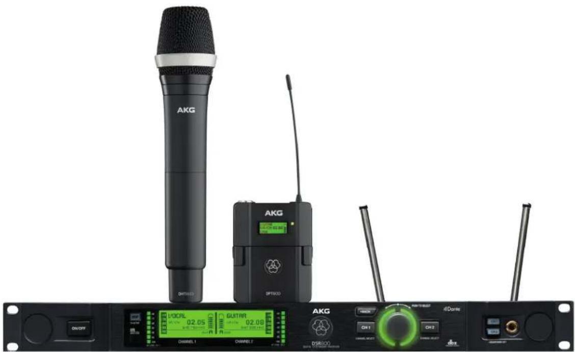
The DMS800 consists of the following parts:
- DSR800 digital stationary true diversity transmitter
• DHT800 handheld transmitter and/or DPT800 bodypack transmitter
There is the choice of AKG microphone heads with the handheld transmitter:
Both the receiver and the transmitter operate in a switching bandwidth of up to 150 MHz. The country-specific frequency bands work within a UHF band from 548 to 832 MHz.
This means you can select the receiver frequency from the preprogrammed frequency groups and channels (presets) of your receiver or set them directly in 25-kHz increments.
Both the handheld and the bodypack transmitters are programmed to the parameters set on the receiver via infrared transmission.
MUTE switch
5.2 Functions of the external MUTE switch (optional)
The optional, external MUTE switch RMS4000 allows the bodypack transmitter to be switched to mute even if the transmitter is fitted in a way that makes the integrated MUTE switch hard to access.
5.3 Technical data
System data
| Carrier frequency range (country-dependent) | Band 1: 548.1 – 697.9 MHzBand 2: 710.1 – 831.9 MHz |
| Switching bandwidth ≤ 150 MHz (country-dependent) | |
| Audio bandwidth | 30 Hz – 20 kHz (± 3 dB) |
| THD | typ. 0.08 % |
System data
| Signal-to-noise ratio (A-weighted) | analog: XLR symmetrical, typ. 112 dB (A) digital: AES-EBU, typ. 120 dB (A) digital: DanteTM Net. Interface, typ. 120 dB (A) |
| Audio sampling rate 24 Bit / 44.1 kHz | |
| Modulation | GFSK |
| Bit rate < 200 kbps | |
| Compressor AKG Premium Audio Compressor/dbx® technology | |
| Latency time | typ. 3.9 ms |
| Encryption | 512-Bit, switchable (no additional latency time) |
DSR800
Digital True Diversity receiver DSR800
| Carrier frequency range (country-dependent) | Band 1: 548.1 – 697.9 MHz |
| Band 2: 710.1 – 831.9 MHz | |
| Switching bandwidth ≤ 150 MHz (country-dependent) | |
| Channels 2 (dual receiver) | |
| Sensitivity 10 dBμV / -97 dBm | |
| Image frequency and spurious attenuation | ≥ 95 dB |
| Receiver design Super-Heterodyne | |
| Diversity system Digital True Diversity | |
| Antenna inputs 2 x 50 Ω BNC sockets | |
| Audio outputs 2 x analog: XLR symmetrical | |
| 2 x analog: 6.3 mm jack, unbalanced | |
| 1 x digital: AES-EBU XLR (48 kHz) with BNC Wordclock input | |
| 1 x digital: DanteTM (Ethernet) (48 kHz) | |
| Audio output level | XLR bal.: typ. +14 dBu (max.); 6.3 mm jack, un-balanced: typ. +8 dBu |
DSR800
Digital True Diversity receiver DSR800
| Bass roll off | 2nd order shelving filter, selectable betw. 10–300Hz |
| Equalizer 3-band (amplification or padding of the lows, mids and highs) | |
| Compressor dbx® (parameters: amplification, response threshold, ratio, attack, release) | |
| Limiter dbx® (parameter: usage threshold) | |
| Transmitter battery indicator | 7-segments |
| PC interface | Ethernet via HUB4000 Q (optional)Ethernet via DanteTM (100 Mbit/s)Software HiQnet Audio Architect |
| Power supply 100 - 240 V AC, 50 - 60 Hz, 0.4 A | |
| Dimensions | Standard housing for rack mounting, 1 RU480(W)x45(H)x230(D) mm/ 189(W)x18(H)x91(D) in |
| Net weight | 2.38 kg / 84 oz |
DPT800
Digital bodypack transmitter DPT800
| Carrier frequency range (country-dependent) | Band 1: 548.1 – 697.9 MHzBand 2: 710.1 – 831.9 MHz |
| Switching bandwidth ≤ 150 MHz (country-dependent) | |
| Transmission power 10, 20, 30, 50 mW (ERP max.), can be set via menu (country-dependent) | |
| Scatter ≤ -70 dBc | |
| Antenna | λ/4 antenna |
| Audio input | 3-pol. Mini-XLR socket (3.0 Vrms max.) |
| Audio input gain | 0 dB, +10 dB, +20 dB switchable |
| Operating time | typ. 6.5 hours (2 x 1.5 V LR6 AA batteries)typ. 6.5 hours (2 x 1.2 V AA NiMH rechargeable batteries >2100 mAh) |
| Dimensions | 65(W)x28(H)x82(D) mm/ 25.6(W)x11(H)x82.3(D) in |
| Net weight | 88 g / 3.10 oz without batteries |
DHT800
Digital handheld transmitter DHT800
| Carrier frequency range (country-dependent) | Band 1: 548.1 – 697.9 MHzBand 2: 710.1 – 831.9 MHz |
| Switching bandwidth ≤ 150 MHz (country-dependent) | |
| Transmission power 10, 20, 30, 50 mW (ERP max.), can be set via menu (country-dependent) | |
| Scatter ≤ -70 dBc | |
| Antenna Integrated helix antenna | |
| Optional microphone heads | D5 WL1: dynamic (supercardoid)D7 WL1: dynamic (supercardoid)C5 WL1: Condenser (cardoid) |
| Max. sound pressure level | DHT800 / D5 WL1 (0 dB gain): ≤ 144 dB SPLDHT800 / D7 WL1 (0 dB gain): ≤ 140 dB SPLDHT800 / C5 WL1 (0 db gain): ≤ 144 dB SPL |
| Audio input gain | 0 dB, +10 dB switchable |
| Operating time | typ. 6.5 hours (2 x 1.5-V LR6 AA batteries)typ. 6.5 hours (2 x 1.2-V AA NiMH rechargeable batteries >2100 mAh) |
| Dimensions | 37(ø)x170(L) mm/ 14.6(ø)x67(L) in (without WL1 head) |
| Net weight | 129 g / 4.6 oz (without WL1 head, no batteries) |
DSR800 controls
5.4 DSR800: Description of the controls
The following table describes the controls of the DSR800 (figure from 115):
No. Description
| 1 POWER: On/off switch |
| 2 DSP button |
| 3 Display |
| 4 BACK button |
| 5 SELECT wheel (turn left/right, press) |
No. Description
| 6 Headphone buttons (CH1, CH2) |
| 7 Headphone output: 6.3 mm jack socket |
| 8 Infrared receiver window for data synchronization |
| 9 HF level indicator |
| 10 Channel selector button for channel CH1 |
| 11 Light ring for status display for channel CH1 and CH2 (red = warning, green = OK) |
| 12 Channel selector button for channel CH2 |
| 13 Opening for antenna front mounting |
| 14 Antenna input A: BNC socket |
| 15 Antenna input B: BNC socket |
| 16 GROUND LIFT switch for XLR output from channel CH1 |
| 17 Balanced analog audio output, channel CH1, on XLR jack (male) |
| 18 Unbalanced analog audio output, channel CH1, on 6.3 mm jack socket |
| 19 GROUND LIFT switch for XLR output from channel CH2 |
| 20 Balanced analog audio output, channel CH2, on XLR socket (male) |
| 21 Unbalanced analog audio output, channel CH2, on 6.3 mm jack socket |
| 22 Data interface: RJ10 socket for connecting the receiver to a computer via HUB4000 Q |
| 23 DanteTM output: Ethernet socket |
| 24 AES-EBU WORDCLOCK IN (48 kHz): BNC socket |
| 25 Digital AES-EBU audio output, CH1 and CH2 (48 kHz), to XLR male socket) |
| 26 IEC mains connection (100 – 240 V AC) |
DSR800 display
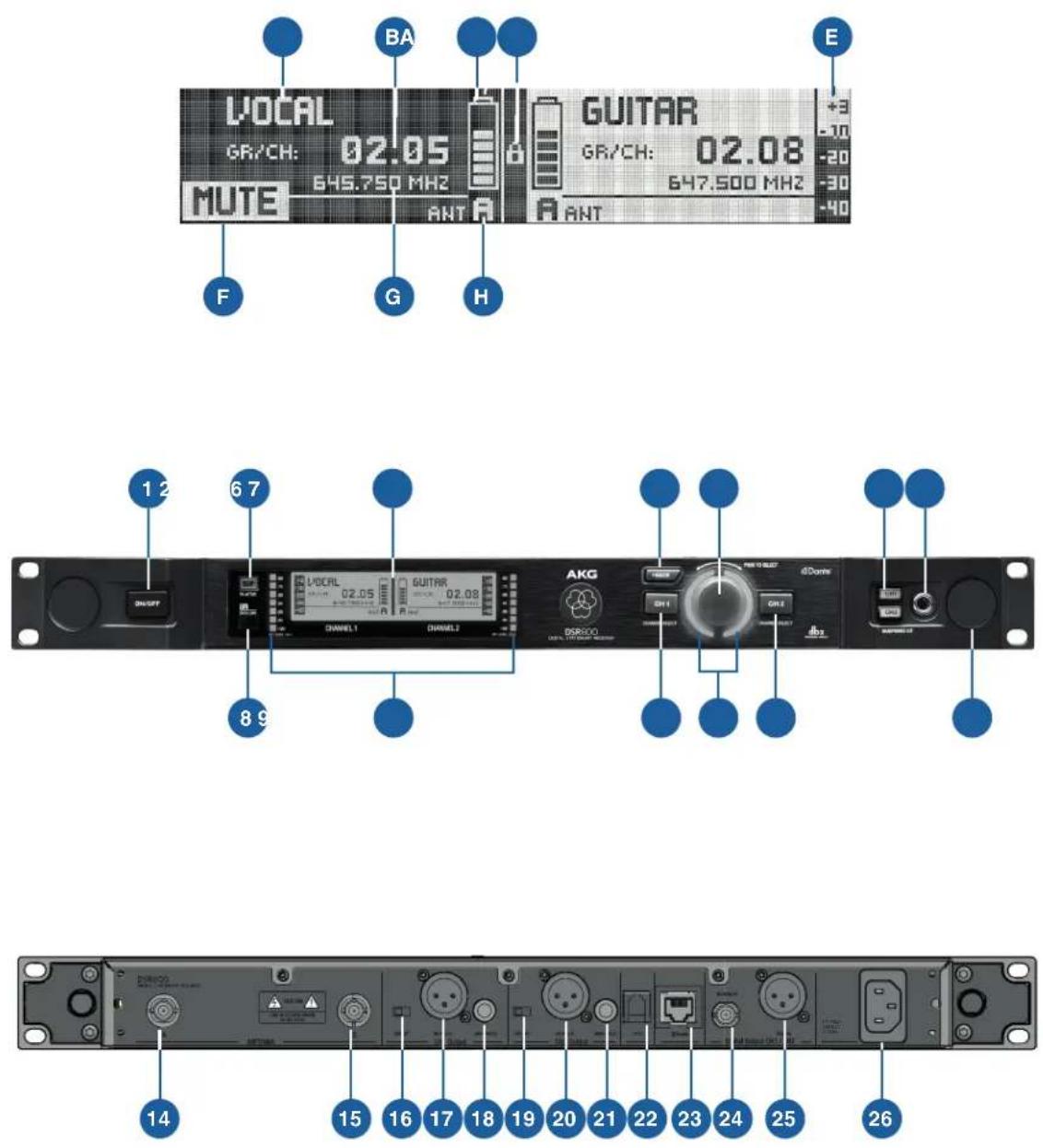
5.5 DSR800: Description of the display elements
The following table describes the displays of the DSR800
(figure from 115):
Letter Description
| A Alphanumeric name display |
| B Current group and channel number |
| C 7-part status display of the transmitter battery |
| D Symbol for LOCK mode (button lock) |
| E Audio level indicator |
| F MUTE symbol |
| G Current frequency |
| H Antenna currently active |
DPT800 controls
5.6 DPT800: Description of the controls
The following table describes the controls of the DPT800
(figure from 116):
No. Description
| 1 Display |
| 2 MUTE switch |
| 3 /4 antenna |
| 4 Infrared receiver diode for transmitter synchronization |
| 5 Status LED (red = warning, green = OK) |
| 6 On/off switch |
| 7 Battery compartment cover |
| 8 Audio input for microphone or instrument: 3-pole |
No. Description
9 Battery compartment for 2 LR6 (AA) 1.5 V batteries or 1.2 V NiMH rechargeable batteries, size AA (>2100 mAh)
10 2.5 mm jack socket for external MUTE switch
11 Charging contacts
12 Locking button for battery compartment cover
DPT800 display
5.7 DPT800: Description of the display elements
The following table describes the displays of the DPT800 (figure from 116):
Letter Description
A Alphanumeric name display
B Current group and channel number
C 7-part status display of the transmitter battery
D Country code or HF level
E Symbol for active encryption
F Symbol for activated muting
DHT800 controls
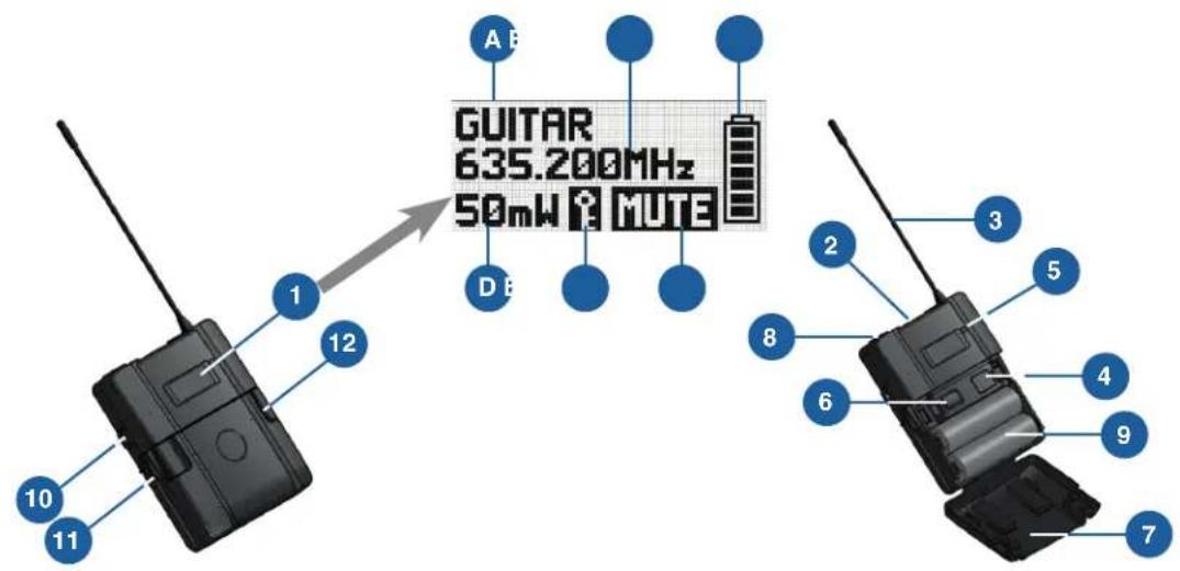
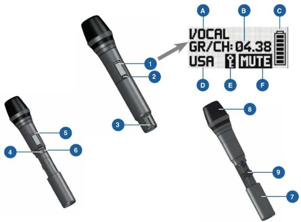
5.8 DHT800: Description of the controls
The following table describes the controls of the DHT800 (figure from 116):
No. Description
1 Display
2 MUTE switch
3 Charging contacts, helical antenna
4 Infrared receiver diode for transmitter synchronization
No. Description
5 Status LED (red = warning, green = OK)
6 On/off switch
7 Battery compartment cover
8 Microphone heads D5 WL1, D7 WL1 or C5 WL1
9 Battery compartment for 2 LR6 (AA) 1.5 V batteries or 1.2 V NiMH rechargeable batteries, size AA (>2100 mAh)
DHT800 display
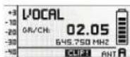
5.9 DHT800: Description of the display elements
The following table describes the displays of the DHT800 (figure from 116):
Letter Description
A Alphanumeric name display
B Current group and channel number
C 7-part status display of the transmitter battery
D Country code or HF level
E Symbol for active encryption
F Symbol for activated muting

6 Commissioning
Before commissioning your DMS800, check that the transmitter and receiver are set to the same frequency.
To commission the DMS800, proceed as follows:
- Insert batteries into the transmitter
- Connect the antennas
- Position the receiver
- Connect the receiver to the mixing console/amplifier
- Reposition the GROUND LIFT switch (optional)
- Connect the receiver to the power network
6.1 Insert batteries into the transmitter
Step Description

1 Open the battery compartment cover (9)
2 Insert batteries into the battery compartment.
When inserting the batteries, note the symbols in the battery compartment to ensure the power supply.
3 Close the battery compartment cover (9)
6.2 Connecting the antennas
The following antennas can be mounted on the receiver:
- / 4 antennas (included as standard)
For all applications where there is a line of sight between the transmitter and receiver antennas.
- Remote antennas
For applications where the reception conditions are not optimal at the receiver position.
To mount the /4 antennas, proceed as follows:
Step Description
1 Mount /4 antennas onto the front panel (13); use BNC front mounting cable (AKG part no. 0110E01890) to do this.
To mount the remote antennas, proceed as follows:
Step Description
1 Connect remote antennas with BNC sockets (14) and (15) to the rear of the receiver; use a RG58 cable to do this
More information on antennas, accessories and help on frequency planning can be found on our website at www.akg.com.
6.3 Position the receiver
Reflections of the transmitter signal on metal parts, walls, ceilings, etc. or shadows from human bodies can weaken or wipe out the direct transmitter signal.
For this reason, observe the following points when setting up the receiver or the remote antennas:
- Always position the receiver/antennas close to the action area (stage), ensuring a minimum distance between the transmitter and receiver/antennas of 3m to an optimal 5m
- Avoid shadows of the transmitter signal from persons or objects as these can interrupt the radio link. The requirement for optimal reception is the line of sight between the transmitter and receiver/antennas.
- Position the receiver/antennas at a distance greater than 1.5 m away from large metal objects, walls, platform structures, ceilings, etc.
The receiver can be set up either freestanding or in a 19" rack.
When installing one or more receivers in a 19" rack, the antennas supplied are mounted onto the receiver front panel or remote antennas are used. This is the only way to guarantee optimal reception quality.


6.4 Connecting the receiver to the mixing console/amplifier
The DSR800 receiver has the following outputs
- Analog outputs
- Digital outputs
XLR output
6.4.1 Analog outputs
Both analog XLR outputs (17, 20) and both analog 6.3 mm jack outputs (18, 21) can be connected at any time. The output level can be set accordingly in the AUDIO menu.
To connect the analog outputs, proceed as follows:
Step Description
1 BALANCED socket (XLR) to microphone input: Move the output level switch to the "-30 dB" position
2 BALANCED socket (XLR) on line input: Move the output level switch to the "0 dB" position
3 Connect the UNBALANCED socket (6.3 mm jack) to unbalanced microphone or line input to the 6.3 mm jack socket
Dante™
6.4.2 Digital output: Dante™
The Dante ^™ technology ^2 represents a digital audio network technology developed by Audinate that can mean up to 256 channels via standard IP-based components, such as Ethernet cables.
The Dante ^™ interface of the DSR800 has a data transfer speed of 100 Mbit/s.
The Dante ^™ Controller Software can be used to configure and manage all devices compatible with the Dante ^™ network.
The Dante™ Controller Software can be downloaded free of charge from www.audinate.com.
The Dante ^™ Controller Software automatically connects to the Dante ^™ network in the default setting.

CAUTION: If you set the IP address of the Dante™ network manually via the software, it is essential that you note down the IP address set.
Alternatively, before removing the device from the network, set the IP address to "Automatic" using the software so that the device is detected in a new network by the Dante™ Controller Software.
To connect the Dante ^TM digital output, proceed as follows:
Step Description
1 Connect the Dante ^TM digital output according to the Dante ^TM Controller Software with the required Dante ^TM digital input
AES-EBU
6.4.3 Digital output: AES-EBU
To connect the digital outputs, proceed as follows:
Step Description
1 Connect the balanced AES-EBU digital output on the XLR socket (25) to the required AES-EBU digital input
The integrated Wordclock Generator supports a sampling rate of 48 kHz. To synchronise all digital signals on the system, an external 48 kHz clock generator can be connected to the BNC socket Wordclock IN (24).
The receiver detects the external 48kHz clock signal automatically and uses the external clock signal from this time. The current clock status can be checked in the channel window.
GROUND LIFT
6.5 Reposition the GROUND LIFT switch (optional)
The GROUND LIFT switch (16, 19) is used to isolate the housing mass connection: This allows hum caused by earth loops to be removed.
To isolate the housing mass connection, proceed as follows:
Step Description
1 Move the GROUND LIFT switch (16, 19) in the LIFT position The switch position is displayed in the channel window.

6.6 Connecting the receiver to the power network
Check that the mains voltage on the rear of the receiver matches the mains voltage at the place of use to avoid damage to the equipment.
To connect the receiver to the power network, proceed as follows:
Step Description
1 Connect the mains cable to the AC IN socket (26) on the rear of the receiver and plug into a suitable mains socket
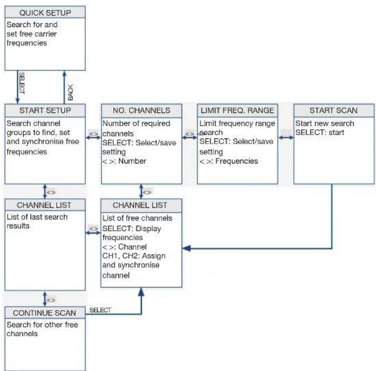
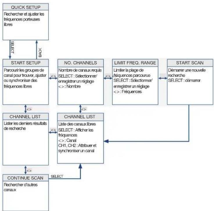
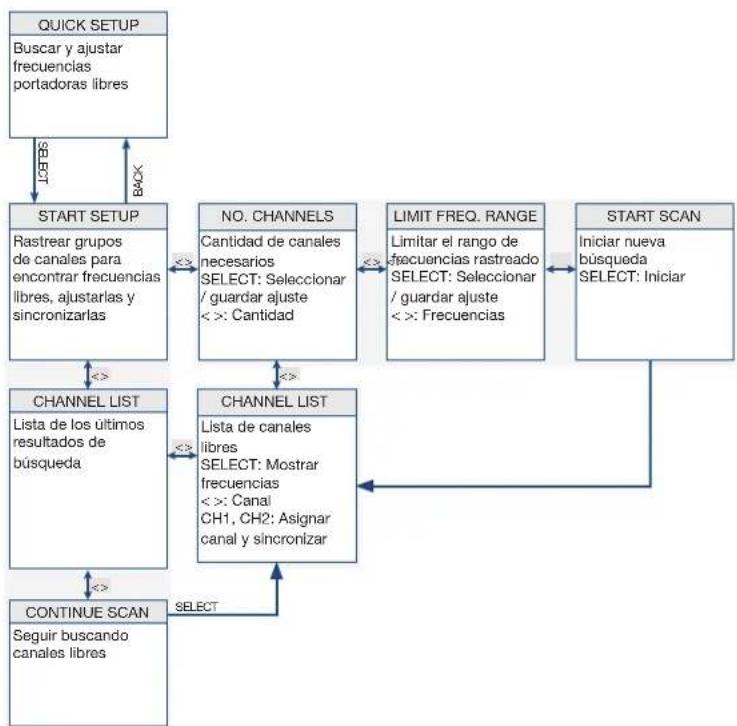
7 QUICK SETUP
The QUICK SETUP function allows intermodulation and interference-free carrier frequencies to be found for all channels quickly and easily.
To carry out a QUICK SETUP, proceed as follows:
Step Description
| 1 Switch on the receiver by pressing the ON/OFF switch |
| 2 Select the START SETUP menu by pressing the SELECT wheel three times |
| 3 Confirm the number of channels by pressing the SELECT wheel once |
| 4 Make frequency ranges unlimited by pressing the SELECT wheel once |
| 5 Start the search by pressing the SELECT wheel onceThe entry SCANNING appears on the display.The search can take up to one minute. After the search is complete, the channel list appears. |
| 6 Assign channel 1 by pressing CH1On the display, the question is shown as to whether or not to assign the channel. |
| 7 Confirm the channel assignment by pressing the SELECT wheel once |
| 8 Prepare the transmitter by inserting batteries and switching on |
| 9 Synchronise the receiver with the transmitter by pressing the SELECT wheel once |
Step Description
10 Keep the transmitter's infrared sensor at a distance of approx. 10 cm of the receiver's infrared sensor
The receiver display shows a message confirming the successful synchronization.
11 Return to the channel list by pressing the BACK wheel once
12 Select channel 2 by turning the SELECT wheel to the right
On the display, the question is shown as to whether or not to assign the channel.
13 Assign channel 2 by pressing CH2
14 Repeat steps 7 to 10
8 Operating instructions
Carrier frequency
8.1 Setting the carrier frequency
The following steps are required to set the carrier frequency:
- Set the transmitter to SILENT mode (recommendation)
- Unlock the receiver
SILENT mode
8.1.1 Setting the transmitter to SILENT mode
We recommend setting the carrier frequency in SILENT mode (no HF radiation). This is the only way to avoid "going to transmit" on an unauthorized frequency and potentially disrupt other radio services or wireless microphones.
To set the transmitter to SILENT mode, proceed as follows:
Step Description
1 When switching on the MUTE switch (2), press with the ON/OFF switch (6) held down at the same time
The entry RF-OFF is shown on the display.

Unlocking the receiver
8.1.2 Unlocking the receiver
The receiver is electronically locked to avoid any settings being changed accidentally. The receiver switches to LOCK mode after approx. 4 minutes with no button being pressed.
The "LOCK" symbol (D) lights up on the display.
The automatic lock function can be deactivated in the AUTOLOCK submenu.
To unlock the receiver, proceed as follows:
Step Description
1 Press SELECT wheel (5) for approx. 2 seconds
The "LOCK" symbol disappears from the display.
The receiver is in SETUP mode.
MUTE LOCK
8.2 Switch on MUTE LOCK
To avoid the MUTE switch on the transmitter being switched on accidentally, it can be locked via the receiver.
To lock the MUTE switch, proceed as follows:
Step Description
1 Switch on the receiver
2 Select the CHANNEL menu; to do this, turn the SELECT wheel to the right
3 Press SELECT
4 Select the MUTE LOCK menu; to do this, turn the SELECT wheel to the right
5 Press SELECT
The MUTE LOCK menu is opened.
MUTE LOCK is on OFF.
6 Press SELECT
MUTE LOCK is on ON and is activated.
Programming the transmitter to the receiver
8.3 Programming the transmitter to the receiver settings
During synchronization, the receiver monitors all previously selected transmitter settings (group/channel, frequency, name, input level of the bodypack transmitter, transmitter output, encryption and MUTE LOCK).
To program the transmitter to the receiver settings, follow the QUICK SETUP steps up to point 10.
REHEARSAL
8.4 Carrying out a REHEARSAL
To carry out a REHEARSAL, proceed as follows:
Step Description
| 1 Switch on the receiver |
| 2 Select the REHEARSAL menu; to do this, turn the SELECT wheel to the right |
| 3 Switch on synchronized transmitter |
| 4 Start REHEARSAL; to do this, press SELECT twiceThe display shows the receive signal level and the time advance in graphic form. |
| 5 Exit the action area with transmitter |
| 6 Mark individual positions; to do this, press the MUTE button on the transmitterThe corresponding marks will appear on the receiver display.Note that the receive level should never drop below -85 dBm.Reception can be improved by changing the position of the receiver antenna. |
| 7 Move the graphic to the left or right by turning the SELECT wheelEnlarge the graphic by pressing the SELECT wheel |

Selecting the country
8.5 Selecting the country
Use the frequencies of the sets preprogrammed for your country. However, ensure that you have the license for the transmission frequencies of the country, if required.
To select the country, proceed as follows:
Step Description
1 Switch on the receiver
Step Description
2 Select the UTILITY menu; to do this, press the SELECT wheel and turn to the right
3 Select the COUNTRY menu; to do this, press the SELECT wheel and turn to the right
4 Press the SELECT wheel
Select the country-specific frequency set.
If your country is not listed, select the SD (standard) setting.
Listening to the audio signal
8.6 Listening to the audio signal
To listen to the audio signal, proceed as follows:
Step Description
1 Plug headphones with 6.3 mm stereo jack plug into the headphones output (7)
2 Activate the audio signal; to do this, tap the Headphones CH1 or CH2 (6) button
3 Deactivate the audio signal; to do this, press the Headphones CH1 or CH2 (6) button for at least one second
DSR800 receiver
9 Controls on the receiver
The functions of the individual controls on the receiver vary depending on the receiver mode.
The following modes are possible:
- LOCK mode: Receiver is locked, no setting options
- SETUP mode: Receiver is unlocked, setting options available
SELECT wheel
9.1 Functions of the SELECT wheel (5)
9.1.1 Functions in LOCK mode
Long press Unlock the receiver (switch to SETUP mode)
Tap Confirm status and warning messages
Turn to the left or right No function
9.1.2 Functions in SETUP mode
Long press Lock the receiver (switch to LOCK mode)
Tap Open the selected menu or confirm selected setting
Turn to the left or right Select a menu or change the selected setting
Main window
9.1.3 Possible functions in the main window
QUICK SETUP menu Directly select and synchronise every free channel in the list of channels
CHANNEL menu Open the submenu (Frequency, Group/Channel, Name...) with the required channel Select another channel in the channel sub-menu
AUDIO menu Select the receiver channel CH1 or
CH2 in the submenus GAIN, DSP and
ATTENUATION PAD.
REHEARSAL menu Scroll through the HF level
CH1, CH2 buttons
9.2 Functions of the CH1, CH2 (10, 12) buttons
9.2.1 Functions in LOCK mode
In the main window Channel window for parameter overview, no changes possible
9.2.2 Functions in SETUP mode
In the main window Channel window for parameter setting, no changes possible
BACK-Taste
9.3 Functions of the BACK button (4)
Tap Close current menu
All unconfirmed values are deleted
Long press Close all menus
All unconfirmed values are deleted
The main window is displayed
DSP button
9.4 Functions of the DSP button (2)
The factory settings of the DSP button can be found in section "16.1 DSP profiles: Factory settings" on page 114.
In the main window Deactivate the LOW CUT, EQ, COMPRESSOR and LIMITER functions for the corresponding channel
In the AUDIO submenu Set the parameters of the digital signal processor
Headphones
CH1
CH2
9.5 Functions of the headphones buttons CH1, CH2 (6)
Tap Put the audio signal on the headphones output
The volume can be set by turning the SELECT wheel.
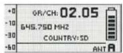
10 Display of the receiver
Main window
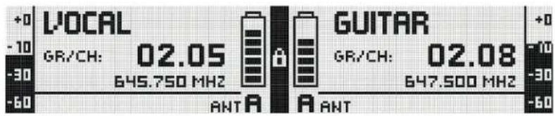
10.1 Main window
After the DSR800 receiver is switched on, the main window is displayed.
The main window displays all parameters required for operation:
- Name
- Current frequency
- Current frequency group
- Current channel
- Audio level
• Active antenna - Remaining operating time of the transmitter battery
With critical operating conditions (low reception level, battery almost empty, audio clipping), a warning message appears.
Battery indicator
10.2 Battery indicator
The battery indicator on transmitter (C) and receiver (C) allow the remaining capacity of the transmitter battery to be checked.
Each segment corresponds to approx. 1 hour remaining playback time. If no battery voltage is measured or the information is invalid, there is no indicator on the display. Around 1 hour before the battery is empty, the warning message "LOW BATT" and the light ring on the SELECT wheel turns red.
Audio level
10.2.1 Audio level indicator (E)
The audio level indicator (E) displays the audio input level of the receiver.
To modify the output level of the receiver to the connected mixing console, the output level can be adjusted in the GAIN submenu in the AUDIO menu.
MUTE indicator
10.2.2 MUTE indicator

The audio output is muted. The light ring (11) lights up red.
As the power supply and the HF section remain switched on, no interference is audible.
Antenna indicator
10.2.3 Antenna indicator
The DSR800 receiver is a specially developed, digital True Diversity receiver with integrated antenna splitter. The antenna field (H) displays the antenna currently active.
Messages
10.3 Status and warning messages
This function draws attention to critical operating conditions of the system using optical warning messages.
Which warning messages are displayed can be set in the UTILITY → STATUS menu. If one of the selected operating conditions occurs, the light ring on the receiver changes from green to red and a corresponding status display is shown on the display. The warning messages appear in order of urgency.
Depending on the type of warning, the top field of the display continuously displays a large warning for at least 5 seconds. A small warning remains in the bottom display line until the warning is confirmed. The selected warning functions are active in LOCK mode and in SETUP mode.
The corresponding warning messages can be cleared by tapping the SELECT wheel.
Warning displays
10.3.1 Status and warning displays by urgency
Display Symbol Meaning
LOW BATT

The capacity of the transmitter battery will soon be depleted. The light ring changes to red and the display shows a large warning continuously.
AF CLIP

The audio signal overrides the A/D converter of the transmitter.
The light ring changes to red and the display shows a large warning for the duration of the error status, but for at least 5 seconds.
A small warning remains in the main window until the warning is confirmed.
LOW RF

The field strength of the reception signal is so low that the receiver is automatically muted to avoid interference noise.

The light ring changes to red and the display shows a large warning for the duration of the error status, but for at least 5 seconds.
A small warning remains in the main window until the warning is confirmed.
ANT ERROR

The same antenna has already been active for more than two minutes.

The light ring changes to red and the display shows a large warning for the duration of the error status, but for at least 5 seconds.
A small warning remains in the main window until the warning is confirmed.
Display Symbol Meaning
INTERFERE

Interference signals from other radio microphones, TV, broadcasting equipment, radio transceivers or harmful electrical equipment or electrical installations have been received.

ENCRYPTION

The encryption is not set correctly.
Channel window
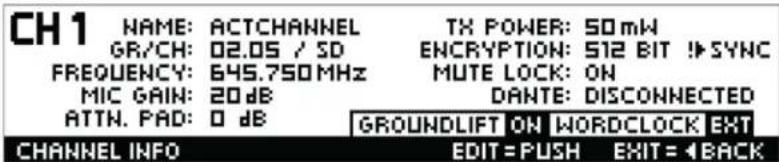
10.4 Channel window
The channel window offers a rapid overview of the following tuning parameters:
- Group/channel
- Frequency
- Name
- Country
• Audio input level of the handheld or bodypack transmitter - Padding (PAD)
• Transmission power - Encryption
- MUTE LOCK
All parameters can be changed and sent to the transmitter.
A gain of +0 dB or +10 dB can be set on the DHT800 handheld transmitter.
The DPT800 bodypack transmitter supports a gain of the audio input signal by +0 dB, +10 dB or +20 dB. The GROUNDLIFT and WORDCLOCK fields display the corresponding current operating condition.
10.4.1 Opening the channel window
To open the channel window, proceed as follows:
Step Description
1 In the main window, press the CH1 (10) or CH2 (12) buttons for the required channel
Transmitter display
11 Display of the transmitter
11.1 Battery indicator
The battery indicator on transmitter (C) and receiver (C) allow the remaining capacity of the transmitter battery to be checked at a glance.
Each segment corresponds to approx. 1 hour remaining playback time. If no battery voltage is measured or the information is invalid, there is no indicator on the display.
Around 1 hour before the battery is empty, the warning message "LOW BATT" appears on the receiver and the light ring on the receiver turns red.
12 Menu structure of the receiver
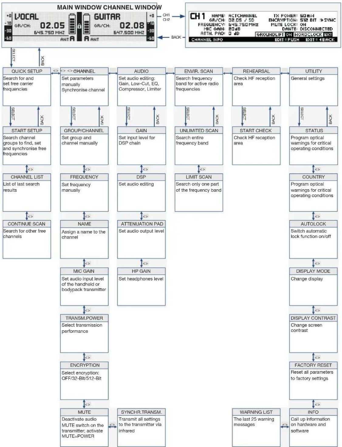
flowchart
graph TD
    A["MAIN WINDOW CHANNEL WINDOW"] --> B["QUICK SETUP"]
    B --> C["CHANNEL"]
    C --> D["AUDIO"]
    D --> E["ENVIR. SCAN"]
    E --> F["REHEARSAL"]
    F --> G["UTILITY"]
    G --> H["STATUS"]
    H --> I["COUNTRY"]
    I --> J["AUTOLOCK"]
    J --> K["DISPLAY MODE"]
    K --> L["CHANGE DISPLAY"]
    L --> M["FACTORY RESET"]
    M --> N["WARNING LIST"]
    N --> O["INFO"]

    subgraph ChannelWindow
        P["LOCAL 02.05 645.750 MHz 02.08 647.500 MHz"]
        Q["GR/CH: -30 645.750 MHz 02.08 647.500 MHz"]
        R["GUITAR 02.08 647.500 MHz"]
        S["ANT A ANT"]
        T["CH1 CH2"]
        U["CH1 NAME: ACTCHANNEL TX POWER: 50MHz ENCRYPTION: 512 BIT SYNC MUTE LOCK: ON DATN PAD: 0 dB DANTE: DISCONNECTED"]
        V["CH1 INFO: GROUNDLIFT ON HORDCLOCK EXT EDIT=PUSH EXIT=1BACK"]
        W["CH1 ACTION: 645.750 MHz 02.08 647.500 MHz"]
        X["CH1 ACTION: 645.750 MHz 02.08 647.500 MHz"]
        Y["CH1 ACTION: 645.750 MHz 02.08 647.500 MHz"]
        Z["CH1 ACTION: 645.750 MHz 02.08 647.500 MHz"]
        AA["CH1 ACTION: 645.750 MHz 02.08 647.500 MHz"]
        AB["CH1 ACTION: 645.750 MHz 02.08 647.500 MHz"]
        AC["CH1 ACTION: 645.750 MHz 02.08 647.500 MHz"]
        AD["CH1 ACTION: 645.750 MHz 02.08 647.500 MHz"]
        AE["CH1 ACTION: 645.750 MHz 02.08 647.500 MHz"]
        AF["CH1 ACTION: 645.750 MHz 02.08 647.500 MHz"]
        AG["CH1 ACTION: 645.750 MHz 02.08 647.500 MHz"]
        AH["CH1 ACTION: 645.750 MHz 02.08 647.500 MHz"]
        AI["CH1 ACTION: 645.750 MHz 02.08 647.500 MHz"]
        AJ["CH1 ACTION: 645.750 MHz 02.08 647.500 MHz"]
        AK["CH1 ACTION: 645.750 MHz 02.08 647.500 MHz"]
        AL["CH1 ACTION: 645.750 MHz 02.08 647.500 MHz"]
        AM["CH1 ACTION: 645.750 MHz 02.08 647.500 MHz"]
        AN["CH1 ACTION: 645.750 MHz 02.08 647.500 MHz"]
        AO["CH1 ACTION: 645.750 MHz 02.08 647.500 MHz"]
        AP["CH1 ACTION: 645.750 MHz 02.08 647.500 MHz"]
        AQ["CH1 ACTION: 645.750 MHz 02.08 647.500 MHz"]
        AR["CH1 ACTION: 645.750 MHz 02.08 647.500 MHz"]
        AS["CH1 ACTION: 645.750 MHz 02.08 647.500 MHz"]
        AT["CH1 ACTION: 645.750 MHz 02.08 647.500 MHz"]
        AU["CH1 ACTION: 645.750 MHz 02.08 647.500 MHz"]
        AV["CH1 ACTION: 645.750 MHz 02.08 647.500 MHz"]
        AW["CH1 ACTION: 645.750 MHz 02.08 647.500 MHz"]
        AX["CH1 ACTION: 645.750 MHz 02.08 647.500 MHz"]
        AY["CH1 ACTION: 645.750 MHz 02.08 647.500 MHz"]
        AZ["CH1 ACTION: 645.750 MHz 02.08 647.500 MHz"]
        BA["CH1 ACTION: 645.750 MHz 02.08 647.500 MHz"]
        BB["CH1 ACTION: 645.750 MHz 02.08 647.500 MHz"]
        BC["CH1 ACTION: 645.750 MHz 02.08 647.500 MHz"]
        BD["CH1 ACTION: 645.750 MHz 02.08 647.500 MHz"]
        BE["CH1 ACTION: 645.750 MHz 02.08 647.500 MHz"]
        BF["CH1 ACTION: 645.750 MHz 02.08 647.500 MHz"]
        BG["CH1 ACTION: 645.750 MHz 02.08 647.500 MHz"]
        BH["CH1 ACTION: 645.750 MHz 02.08 647.500 MHz"]
        BI["CH1 ACTION: 645.750 MHz 02.08 647.500 MHz"]
        BJ["CH1 ACTION: 645.750 MHz 02.08 647.500 MHz"]
        BK["CH1 ACTION: 645.750 MHz 02.08 647.500 MHz"]
        BL["CH1 ACTION: 645.75O MAX"]
    end

    %% Labels for each section of the main window
    direction TB
12.1 QUICK SETUP menu
flowchart
graph TD
    A["QUICK SETUP\nSearch for and set free carrier frequencies"] -->|LICTS| B["START SETUP\nSearch channel groups to find, set and synchronise free frequencies"]
    B -->|<<| C["CHANNEL LIST\nList of last search results"]
    C -->|<<| D["CONTINUE SCAN\nSearch for other free channels"]
    D -->|SELECT| E["CHANNEL LIST\nList of free channels SELECT: Display frequencies\n<> Channel CH1, CH2: Assign and synchronise channel"]
    E -->|<<| F["NO. CHANNELS\nNumber of required channels SELECT: Select/save setting\n<> Number"]
    F -->|<<| G["LIMIT FREQ. RANGE\nLimit frequency range search SELECT: Select/save setting\n<> Frequencies"]
    G -->|<<| H["START SCAN\nStart new search SELECT: start"]
    H -->|Back| B
12.2 CHANNEL menu
flowchart
graph TD
    A["CHANNEL\nSet parameters manually\nSynchronise channel"] -->|BACK| B["GROUP/CHANNEL\nSet group and channel manually"]
    B -->|SELECT CH1/CH2| C["CH1/CH2\nSelect receiver part SELECT: Select/save setting < : CH1/CH2"]
    B -->|BACK| D["FREQUENCY\nSet frequency manually"]
    D -->|SELECT CH1/CH2| E["CH1/CH2\nSelect receiver part SELECT: Select/save setting < : CH1/CH2"]
    D -->|BACK| F["NAME\nAssign a name to the channel"]
    F -->|SELECT CH1/CH2| G["CH1/CH2\nSelect receiver part SELECT: Select/save setting < : CH1/CH2"]
    F -->|BACK| H["MIC GAIN\nSet audio input level of the handheld or bodypack transmitter"]
    H -->|SELECT CH1/CH2| I["CH1/CH2\nSelect receiver part SELECT: Select/save setting < : CH1/CH2"]
    H -->|BACK| J["TRANSM.POWER\nSelect transmission performance"]
    J -->|SELECT CH1/CH2| K["CH1/CH2\nSelect receiver part SELECT: Select/save setting < : CH1/CH2"]
    J -->|BACK| L["ENCRIPTION\nSelect encryption: OFF/32-Bit/512-Bit"]
    L -->|SELECT CH1/CH2| M["MUTE\nDeactivate audio MUTE switch on the transmitter; activate MUTE=POWER"]
    M -->|SELECT CH1/CH2| N["CH1/CH2\nSelect receiver part SELECT: Select/save setting < : CH1/CH2"]
    M -->|BACK| O["SYNCHR.TRANSM.\nTransmit all settings to the transmitter via infrared"]
    C --> P["GROUP\nSelect group SELECT: select < : Group"]
    P --> Q["CHANNEL\nSelect channel SELECT: select/save < : Channel"]
    Q --> R["SYNC\nSynchronise transmitter SELECT: Start synchronization"]
    R --> S["KHZ\nSelect frequency SELECT: select < : MHz"]
    S --> T["SYNC\nSynchronise transmitter SELECT: Start synchronization"]
    T --> U["PT GAIN\nSet audio input level SELECT: select/save < : 0, +10, +20 dB"]
    U --> V["TRANSM.POWER\nSelect transmission power SELECT: select/save < : Transmission power"]
    V --> W["ENCRIPTION\nSelect encryption: Select/save < : OFF/32-Bit/512-Bit"]
    W --> X["MUTE LOCK\nDeactivate MUTE button on the transmitter SELECT: select/save < : ON/OFF"]
    X --> Y["SYNCR\nSynchronise transmitter SELECT: Start synchronization"]
12.3 AUDIO menu
flowchart
graph TD
    A["AUDIO\nSet audio editing: Gain, bass roll off, EQ, compressor, limiter"] --> B["GAIN\nSet input level for DSP chain"]
    B --> C["CH1/CH2\nSELECT receiver part\nSELECT: Select/save setting\n< : CH1/CH2"]
    C --> D["GAIN\nSet input level for DSP (audio) chain SELECT: select/save\n< : Gain"]
    D --> E["DSP\nSet audio editing"]
    E --> F["PROFILE\nSelect profile\nSELECT: select/save\n< : Profile"]
    F --> G["SAVE\nSave DSP settings in profile with name\nSELECT: select/save\n< : Profile and characters"]
    G --> H["LOW CUT\nSet usage frequency for bass roll off\nSELECT: select/save\n< : Frequency"]
    H --> I["EQ\nSet 3-band equalizer\nSELECT: select/save\n< : Level and frequency"]
    I --> J["COMPRESSOR\nSet gain, trigger threshold, ratio, attack and release\nSELECT: select/save\n< : Value"]
    J --> K["LIMITER\nSet usage threshold\nSELECT: select/save\n< : Value"]
    K --> L["ATTENUATION PAD\nSet audio output level"]
    L --> M["CH1/CH2\nSelect receiver part\nSELECT: Select/save setting\n< : CH1/CH2"]
    M --> N["ATTENUATION PAD\nSet audio input level\nSELECT: Select/save setting\n< : 0 dB/-30 dB"]
    N --> O["HP GAIN\nSet headphones level"]
    O --> P["HP LEVEL\nSet headphones volume\nSELECT: Select/save setting\n< : Level"]
    P --> Q["ATTENUATION PAD\nSET audio output level"]
    Q --> R["CAPS"]
    R --> S["CONTENTS"]
    S --> T["BACK"]
    T --> U["RESET"]
    U --> V["RESET CH1/CH2"]
    V --> W["RESET CH1/CH2"]
    W --> X["RESET CH1/CH2"]
    X --> Y["RESET CH1/CH2"]
    Y --> Z["RESET CH1/CH2"]
    Z --> AA["RESET CH1/CH2"]
    AA --> AB["RESET CH1/CH2"]
    AB --> AC["RESET CH1/CH2"]
    AC --> AD["RESET CH1/CH2"]
    AD --> AE["RESET CH1/CH2"]
    AE --> AF["RESET CH1/CH2"]
    AF --> AG["RESET CH1/CH2"]
12.4 ENVIR. menu SCAN
flowchart
graph TD
    A["ENVIR. SCAN\nSearch frequency band for active radio frequencies"] -->|DEF βS| B["UNLIMITED SCAN\nSearch entire frequency band"]
    B -->|SELECT CH1.CH2| C["GRAPH\nInterference frequencies are searched\nSELECT: Enlarge display\n< : move to the left or right"]
    B -->|BACK| D["LIMIT SCAN\nSearch only part of frequency band"]
    C -->|INTERference frequencies are searched\nSELECT: Enlarge display\n< : move to the left or right]
    D -->|SELECT CH1.CH2| E["LOWER LIMIT\nSet lower limit in MHz\nSELECT: Select/save setting\n< : Frequencies"]
    E -->|< >| F["UPPER LIMIT\nSet upper limit in MHz\nSELECT: Select/save setting\n< : Frequencies"]
    F -->|< >| G["START SCAN\nStart new search SELECT: start"]
    G -->|SELECT| H["GRAPH\nSearch interference frequencies\nSELECT: Enlarge display\n< : move to the left or right"]
    H -->|BACK| D
12.5 REHEARSAL menu
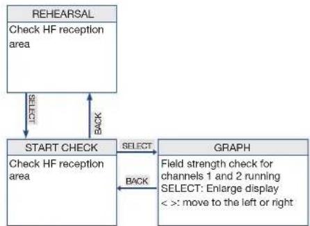
flowchart
graph TD
    A["REHEARSAL"] -->|CHECK| B["START CHECK"]
    B -->|SELECT| C["GRAPH"]
    C -->|BACK| B
    C -->|FIELD strength check for channels 1 and 2 running SELECT: Enlarge display < : move to the left or right]
    B -->|Check HF reception area| A
12.6 UTILITY menu
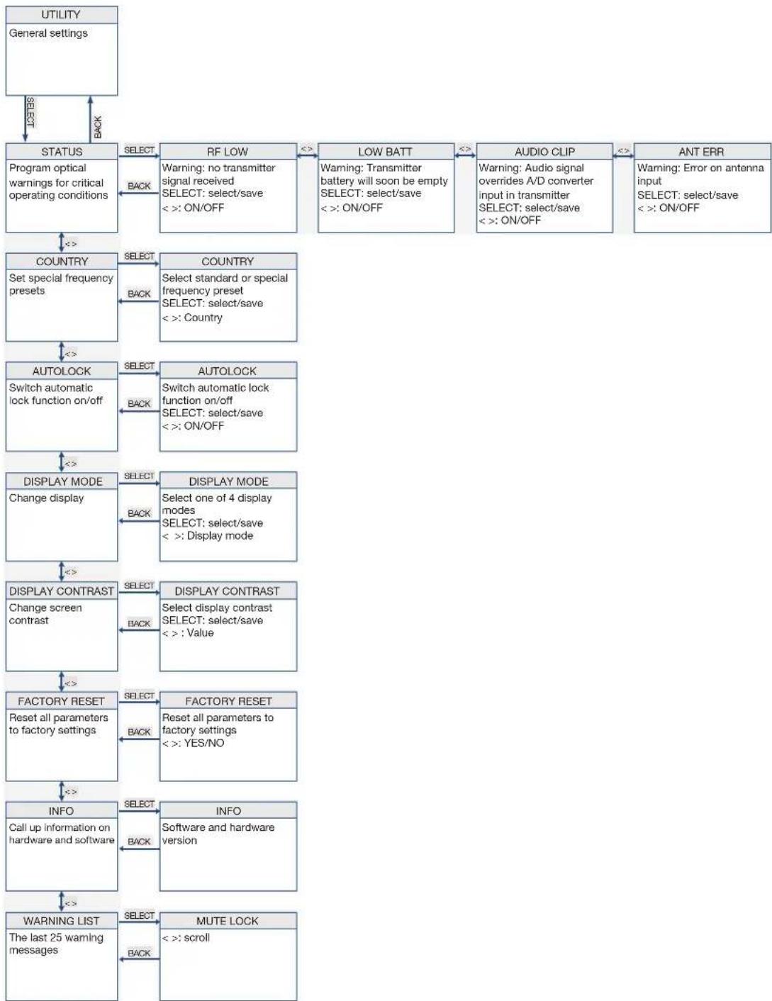
flowchart
graph TD
    A["UTILITY\nGeneral settings"] -->|LAST/BACK| B["STATUS\nProgram optical warnings for critical operating conditions"]
    B -->|SELECT| C["RF LOW\nWarning: no transmitter signal received\nSELECT: select/save\n< : ON/OFF"]
    C -->|<<=>| D["LOW BATT\nWarning: Transmitter battery will soon be empty\nSELECT: select/save\n< : ON/OFF"]
    D -->|<<=>| E["AUDIO CLIP\nWarning: Audio signal overrides A/D converter input in transmitter\nSELECT: select/save\n< : ON/OFF"]
    E -->|<<=>| F["ANT ERR\nWarning: Error on antenna input\nSELECT: select/save\n< : ON/OFF"]
    F -->|<<=>| G["COUNTRY\nSet special frequency presets"]
    G -->|SELECT| H["COUNTRY\nSelect standard or special frequency preset\nSELECT: select/save\n< : Country"]
    H -->|<<=>| I["AUTOLOCK\nSwitch automatic lock function on/off"]
    I -->|SELECT| J["AUTOLOCK\nSwitch automatic lock function on/off\nSELECT: select/save\n< : ON/OFF"]
    J -->|<<=>| K["DISPLAY MODE\nChange display"]
    K -->|SELECT| L["DISPLAY MODE\nSelect one of 4 display modes\nSELECT: select/save\n< : Display mode"]
    L -->|<<=>| M["DISPLAY CONTRAST\nChange screen contrast"]
    M -->|SELECT| N["DISPLAY CONTRAST\nSelect display contrast\nSELECT: select/save\n< : Value"]
    N -->|<<=>| O["FACTORY RESET\nReset all parameters to factory settings"]
    O -->|SELECT| P["FACTORY RESET\nReset all parameters to factory settings\n< : YES/NO"]
    P -->|<<=>| Q["INFO\nCall up information on hardware and software"]
    Q -->|SELECT| R["INFO\nSoftware and hardware version"]
    R -->|<<=>| S["WARNING LIST\nThe last 25 warning messages"]
    S -->|SELECT| T["MUTE LOCK\n< : scroll"]
    T -->|Back| U["BACK"]
13 Menu structure of the transmitter
To switch on the transmitter, proceed as follows:
Step Description
1 Press the ON/OFF button for 2 seconds
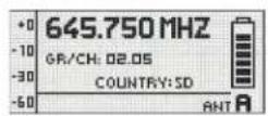
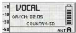
13.1 Preset mode
After synchronization of a group and a channel, the group (GR), channel (CH) and country appear on the display.
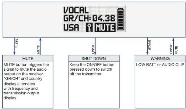
flowchart
graph TD
    A["VOCAL GR/CH:04.38 USA MUTE"] -->|MUTE| B["MUTE"]
    A -->|MUTE| C["SHUT DOWN"]
    A -->|MUTE| D["WARNING"]
    B -->|MUTE button triggers the signal to mute the audio output on the receiver. 'GR/CH' and country display alternates with frequency and transmission output display.| E
    C -->|Keep the ON/OFF button pressed down to switch off the transmitter.| F
    D -->|ON/OFF MUTE| G
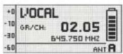
13.2 Frequency mode
After synchronization of a manually set frequency, the frequency and transmitter output appear on the display
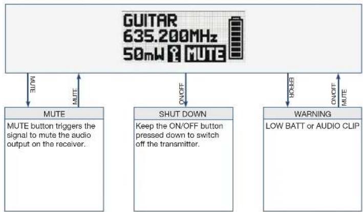
flowchart
graph TD
    A["GUITAR 635.200MHz 50mW MUTE"] -->|MUTE| B["MUTE button triggers the signal to mute the audio output on the receiver."]
    A -->|ON/OFF| C["SHUT DOWN: Keep the ON/OFF button pressed down to switch off the transmitter."]
    A -->|ON/OFF| D["WARNING: LOW BATT or AUDIO CLIP"]
13.3 Silent mode
To switch on the transmitter in silent mode, proceed as follows:
Step Description
1 When switching on the MUTE switch (2), press with the ON/OFF switch (6) held down at the same time The entry RF-OFF is shown on the display.
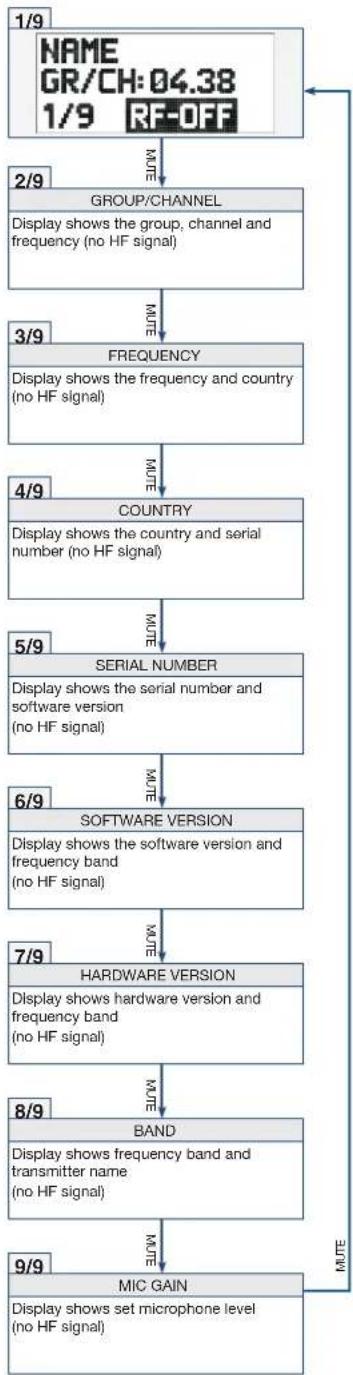
flowchart
graph TD
    A["1/9 NAME GR/CH:04.38 1/9 RF-OFF"] -->|NOTE| B["2/9 GROUP/CHANNEL"]
    B --> C["Display shows the group, channel and frequency (no HF signal)"]
    C -->|NOTE| D["3/9 FREQUENCY"]
    D -->|NOTE| E["4/9 COUNTRY"]
    E -->|NOTE| F["5/9 SERIAL NUMBER"]
    F -->|NOTE| G["6/9 SOFTWARE VERSION"]
    G -->|NOTE| H["7/9 HARDWARE VERSION"]
    H -->|NOTE| I["8/9 BAND"]
    I -->|NOTE| J["9/9 MIC GAIN"]
    J -->|NOTE| K["Display shows set microphone level (no HF signal)"]
14 Functional description
The DSR800 has been developed for operation in large multi-channel systems.
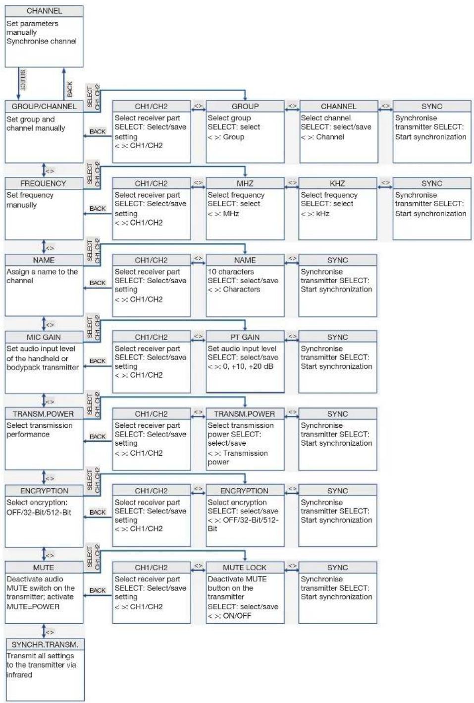
14.1 CHANNEL menu
This menu can be used to manually set all parameters relevant for a channel such as group/channel, frequency, name, input level of the bodypack transmitter, encryption and MUTE LOCK.
The DSR800 receiver provides frequency groups with specially calculated frequencies. The required channel (frequency) can be manually set and synchronized in this menu.
Ensure that all channels are selected from the same group within the same presets. To search for free channels, we recommend the QUICK SETUP function
The following table describes the functions of the submenus in the CHANNEL menu.
Submenu Function
FREQUENCY Set the frequency directly in 25 kHz increments
NAME Assign any name for each channel (name of a musician, instrument, or similar)
MIC GAIN Adjust the audio input level of the transmitter to the connected microphone
TRANSM. POWER Set the transmission power of the synchronized transmitter

Submenu Function
ENCRYPTION Activate the encryption function
When the encryption function is activated, the receiver calculates a one-off key every time a transmitter is synchronized. This key is sent to the transmitter during the synchronization process. The key is not displayed and it is not possible to send the same key to two transmitters.
Note:
For transmitters with firmware versions lower than 2.0, choose the 32-Bit encryption. (These transmitters do not function with 512 Bit encryption.)
For transmitters with firmware version 2.0 or higher you can achieve the highest possible security with 512 Bit encryption.
If you use a replacement transmitter for a channel, the encryption must be deactivated.

MUTE The MUTE LOCK function deactivates the MUTE switch on the transmitter
The transmitter synchronized with the receiver cannot be muted with the MUTE button.
The MUTE=POWER function allows the MUTE button of the transmitter to be used as the on/off switch as well.
SYNCHR. TRANSMITTER
Programming the transmitter to the receiver settings
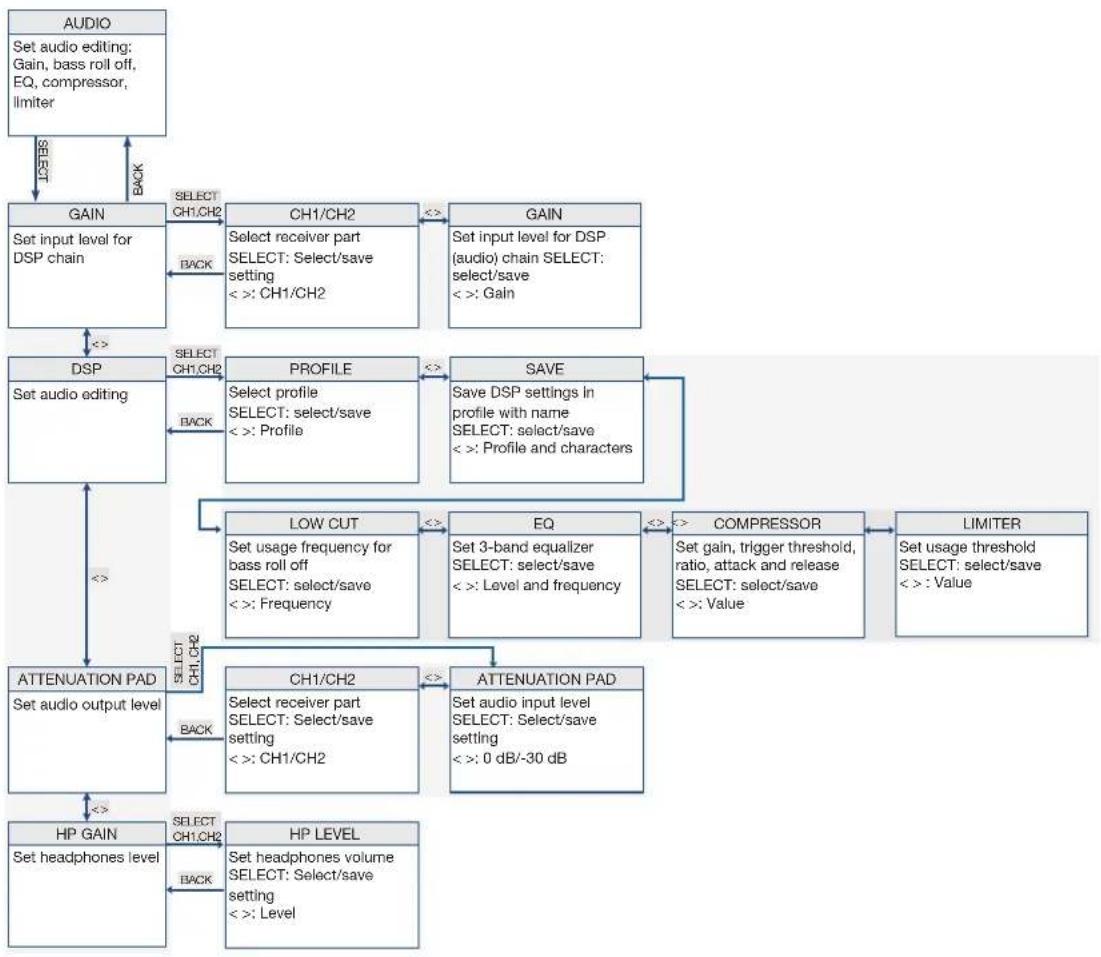
GAIN Set input level of the DSP chain
Submenu Function

| DSP Edit audio signal directly on the receiver | |
| Settings can be stored in one of the nine DSP profiles in a freely selectable name.The digital signal processor offers the following dynamic editing functions:Low Cut (frequency: 10 – 300 Hz)3-band equalizer (low: ±20 dB, 80 Hz shelving; parametric mid: ±20 dB, 100 Hz to 10 kHz, Q = 2; high: ±20 dB, 8 kHz shelving)dbx® compressor (threshold: -60 - +9 dBV, ratio: 1:1 - 1:10, gain: 0 – 20 dB, attack: 1 – 100 ms, release: 1 – 2000 ms)dbx® limiter (threshold: -20 – +9 dBV)Changes to a profile always affect both channels. All previous settings of a profile are overwritten. | |
| ATTENUATION PAD | Modify the level of the balanced audio output to the input sensitivity of the connected equipmentWith microphone inputs, the setting 0 dB can result in overloads.If the receiver is connected to a microphone input, it is recommended to select -30 dB.The unbalanced line output cannot be controlled. |
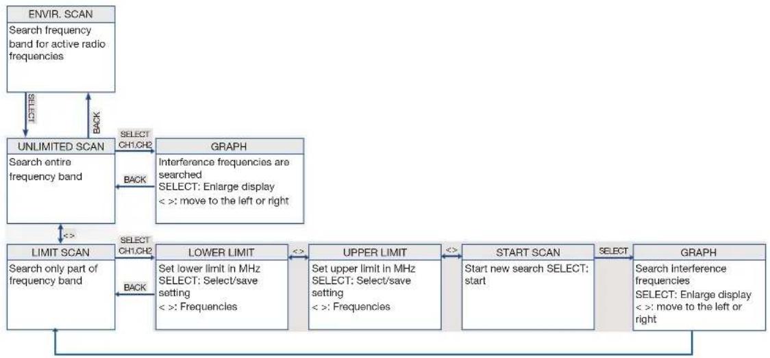
| ENVIRONMENT SCAN | This function works in a similar way to a spectrum analyser.UNLIMITED SCAN: the entire frequency band of the receiver is searched for active radio frequenciesLIMIT SCAN: only a part of the frequency band is searched for active radio frequenciesDuring the search process, the audio output remains muted and the display shows the result graphically.Turn the SELECT wheel: Move the curve to the left or rightPress SELECT: Enlarge curve |
Submenu Function
REHEARSAL Sound check
Check HF level of the transmitter in the action area
The maximum recording time is four minutes
UTILITY STATUS Activate optical warning function for specific critical operating conditions
If one of these operating conditions occurs, the light ring around the SELECT wheel on the receiver changes from green to red and a corresponding status display is shown on the display.
The light ring changes to red and the display shows a large warning for 5 seconds. A small warning remains on the display until the warning is cleared by pressing the SELECT wheel.
The warning messages appear in order of urgency.
The selected warning functions are active in LOCK mode and in ACTIVE mode.
COUNTRY Selecting the country
A country must be selected when switching on the receiver for the first time.
DISPLAY MODE Change the appearance of the display
The following display modes are available
MAIN
FREQUENCY
NAME GROUP/CHANNEL
DISPLAY CONTRAST
Modify the contrast of the display to the current lighting conditions
Submenu Function
FACTORY RESET Reset parameters to factory settings
INFO Call up information on the receiver software and the transmitters synchronized with it
WARNING LIST Calling up warning messages
This function saves the last 25 warning messages.
15 Maintenance and cleaning
15.1 Maintenance
The equipment must only be opened, serviced and repaired by authorized personnel. The equipment contains no user-serviceable parts.
15.2 Cleaning
Caution: Unplug the DSR800 receiver mains cable from the socket!
Clean the surfaces of the equipment with a soft cloth moistened with water, but not wet.
Never use caustic or scouring cleaners or cleaning products containing alcohol or solvents since these may damage the enamel and plastic parts.

16 Troubleshooting
ERROR POSSIBLE CAUSE CORRECTION
| No sound Errors due to other wireless systems, TV, radio, wireless devices or harmful electrical equipment or installations. | Switch off other wireless systems |
| Transmitter set to a frequency different from the receiver. | Set transmitter to the frequency |
| Transmitter switch or MUTE switch on "MUTE". | Switch on transmitter or press the MUTE switch |
| Mains cable is not plugged into the receiver and/or mains socket. | Plug mains cable into the receiver and/ or mains socket |
| Receiver is switched off. Switch on the receiver | |
| Receiver is not connected to the PA system. | Connect receiver to the PA system |
| Microphone or instrument is not connected to the bodypack transmitter. | Connect microphone or instrument to the bodypack transmitter |
| Batteries incorrectly inserted in the transmitter. | Check the insertion direction of the batteries in the transmitter |
| Transmitter batteries or rechargeable batteries empty. | Replace transmitter batteries or rechargeable batteries |
| Transmitter is too far away from the receiver. | Move the transmitter to the receiver |
| Barriers between the transmitter and receiver are creating shadows on the transmitter signal. | Remove the barriers between the transmitter and receiver |
| No line of sight between the transmitter and receiver. | Ensure a clear line of sight between the transmitter and receiver |
| Receiver too close to metallic objects. Remove receiver from metallic objects | |
| Software on the transmitter and receiver does not match. | Check the software |
| Distortions GAIN set too high or too low. | |
| Suboptimal DSP settings. Check the DSP settings | |
ERROR POSSIBLE CAUSE CORRECTION
| Brief dropouts at some points of the action area. | Receiver or antennas incorrectly positioned Reposition receiver or remote antennas.If dropouts remain, mark and avoid critical points. | |
| Transmitter is too far away from the receiver. | Move the transmitter to the receiver | |
| RF LOW The field strength of the reception signal is so low that the receiver is automatically muted to avoid interference noise. | Reposition receiver or use remote antennas. | |
| AF CLIP The audio signal overrides the A/D converter of the transmitter. | Reduce audio input level. | |
| ANT ERROR The same antenna has already been active for more than two minutes. | Check if the antenna cable is faulty or incorrectly connected. | |
| LOW BATT The capacity of the transmitter battery will soon be depleted. | Insert new batteries. | |
| SYSTEM ERROR Internal error. Switch off receiver and switch back on after approx. 10 seconds. If the error occurs again, contact your AKG service centre. | ||
| RF ERROR, PLL ERROR | Receiver cannot be synchronized to the set frequency. | Tap the SELECT wheel to confirm errors and set another frequency. If the error occurs again, contact your AKG service centre. |
| UPDATE FIRMWARE | System is ready for software updates. Switch off receiver and switch back on after approx. 10 seconds. If the error occurs again, contact your AKG service centre. | |
| INTERFERE ERROR | Errors due to other wireless systems, TV, radio, wireless devices or harmful electrical equipment or installations. | Change frequency or switch off device creating the interference. |
| ENCRYPTION! Encryption not set correctly. Synchronise transmitter. | ||
| Errors due to other DMS800 transmitters. Change carrier frequency (resynchronise) | ||
ERROR POSSIBLE CAUSE CORRECTION
| WRONG DEVICE Transmitter and receiver work in different frequency bands | Ensure that the transmitter and receiver are working on the same frequency band | |
| ERROR DEVICE Transmitter data contains errors. If the error occurs frequently, contact your AKG service centre. | ||
| TIMEOUT No infrared data detected. Align the IR window of the transmitter and receiver with one another and resynchronise. | ||
| The remaining battery life time on the display of the transmitter shows a question mark. | The transmitter cannot detect the charge status of the dry batteries. | Insert new batteries. |
| The transmitter cannot detect the charge status of the rechargeable batteries. | Fully charge the rechargeable batteries. | |
16.1 DSP profiles: Factory settings
LOW CUT EQ COMPRESSOR LIMITER
| No. | Profile Name Application | Freq. [Hz] | Low[dB] | Mid[dB] | Mid Freq[kHz] | High[dB] | Threshold[dB] | Ratio | Gain[dB] | Attack[ms] | Release[ms] | Threshold[dB] | |||
| 1 | Presenter | Handheld transmitter | Present HT | Beginners,MS Powerpoint,religious institutions,presenters | 77 0 0 1 | 30 2.1:1 | 3 | 1 | 71 | 0 | |||||
| 2 | Headset | Present PT | 40 | OFF | -25 | 1.5:1 | 5 | 6 | 207 | ||||||
| 3 | Music | Handheld transmitter | Music HT | Experienced users,vocalists, rock bands, karaoke,musical | 40 | OFF | OFF | 9 | |||||||
| 4 | Headset | Music PT | |||||||||||||
| 5 | Instrument | Instrument microphone with bodypack transmitter | Instru PT | Beginners and experts, trumpet,tuba, drums | OFF | OFF | OFF | 9 | |||||||
| 6 | Guitar with bodypack transmitter | Guitar PT | Electric guitar,electric bass, active acoustic guitar | ||||||||||||
| 7-9 UserUser 1-3 | - | ||||||||||||||
17 DMS800: Controls
17.1 DSR800
17.2 DPT800
17.3 DHT800
DMS800
SYSTÈME DE MICROPHONE SANS FIL NUMÉRIQUE
Read the manual before using the equipment!
MODE D'EMPLOI
3.5 Evvironnement 126
flowchart
Ecran principal Ecran de Canal flowchart detailing key components from VOCAL to INFO, including quick setup, audio, scanning, and utility stages.12.1 Menu QUICK SETUP
Read the manual before using the equipment!
MODE D'EMPLOI 117
Menú CHANNEL Abrir el submenú (Frequency, Group/Channel,
10.1 Pantalla principal
flowchart
```mermaid
graph TD
    A["PANTALLA PRINCIPAL VENTANA DE CANALES"] --> B["CH1"]
    B --> C["CH2"]
    C --> D["CH 1 NAME: ACTCHANNEL TX POWER: 50MHz ENCRYPTION: 512 BIT SYNC MUTE LOCK ON DATN: DISCONNECTED"]
    D --> E["CHANNEL INFO GROUNDLIFT ON HORDOCLOCK EXT EDIT=PUSH EXIT=1BACK"]
    E --> F["QUICK SETUP"]
    F --> G["START SETUP"]
    G --> H["CHANNEL LIST"]
    H --> I["CONTINUE SCAN Seguir buscando canales libres"]
    F --> J["FREQUENCY"]
    J --> K["NOMBRE Asignar un nombre al canal"]
    J --> L["MIC GAIN"]
    L --> M["TRANSM.POWER Seleccionar la potencia de transmisión"]
    J --> N["ENCRIPTION Seleccionar la encriptación: OFF/32 bits/512 bits"]
    J --> O["MUTE Desactivar interruptor MUTE en el transmisor; activar MUTE=POWER"]
    F --> P["AUDIO"]
    P --> Q["GAIN"]
    Q --> R["DSP"]
    R --> S["ATTENUATION PAD"]
    S --> T["HP GAIN"]
    T --> U["REHEARSAL Comprobar área de recepción de HF"]
    U --> V["LIMIT SCAN Rastrear sólo una parte de la banda de frecuencias"]
    V --> W["UNLIMITED SCAN Rastrear toda la banda de frecuencias"]
    W --> X["ENVIR. SCAN Buscar frecuencias de radio activas en la banda de frecuencias"]
    X --> Y["STATUS Ajustes generales"]
    Y --> Z["COUNTRY Programar advertencias visuales para estados de funcionamiento críticos"]
    Z --> AA["AUTOLOCK Activar/desactivar función de bloqueo automática"]
    AA --> AB["DISPLAY MODE Cambiar la imagen de pantalla"]
    AB --> AC["DISPLAY CONTRAST Modificar el contraste de la pantalla"]
    AC --> AD["FACTORY RESET Restablecer todos los parámetros a sus ajustes de fábrica"]
    AD --> AE["INFO Acceso a información sobre hardware y software"]

    subgraph CANALES
        F
        Q
        R
        S
        V
        W
        X
        Y
        Z
        AA
        AC
        AD
        AE
        AF
        AG
        AH
        AI
        AJ
        AK
        AL
        AM
        AN
        AO
        AP
        AQ
        AR
        AS
        AT
        AU
        AV
        AW
        AX
        AY
        AZ
        BA
        BB
        BC
        BD
        BE
        BF
        BG
        BH
        BI
        BJ
        BK
        BL
        BM
        BN
        BO
        BP
        BPB
        BPB
        BPB
        BPB
        BPB
        BPB
        BPB
        BPB
    end

    %% Labels on the diagram are non-textual elements; the diagram is structured as a hierarchical structure with labels for each character. The diagram is labeled 'CANALES' and 'CHANNEL' in the top left corner. The diagram is labeled 'CANCE' in the bottom left corner. The diagram is labeled 'UPT' in the bottom right corner. The diagram is labeled 'UPT' in the bottom left corner. The diagram is labeled 'UPT' in the bottom right corner. The diagram is labeled 'UPT' in the bottom left corner. The diagram is labeled 'UPT' in the bottom right corner. The diagram is labeled 'UPT' in the bottom left corner. The diagram is labeled 'UPT' in the bottom right corner. The diagram is labeled 'UPT' in the bottom left corner. The diagram is labeled 'UPT' also contains an arrow pointing to the diagram's top left corner. The diagram is labeled 'UPT' also contains an arrow pointing to the diagram's bottom left corner. The diagram is labeled 'UPT' also contains an arrow pointing to the diagram's bottom right corner. The diagram is labeled 'UPT' also contains an arrow pointing to the diagram's bottom left corner. The diagram is labeled 'UPT' also contains an arrow pointing to the diagram's bottom right corner. The diagram is labeled 'UPT' also contains an arrow pointing to the diagram's bottom left corner. The diagram is labeled 'UPT' also contains an arrow pointing to the diagram's bottom right corner. The diagram is labeled 'UPT' also contains an arrow pointing out to the bottom left corner. The diagram is labeled 'UPT' also contains an arrow pointing out to the bottom right corner. The diagram is labeled 'UPT' also contains an arrow pointing out to the bottom left corner. The diagram is labeled 'UPT' also contains an arrow pointing out to the bottom right corner. The diagram is labeled 'UPT' also contains an arrow pointing out to the bottom left corner. The diagram is labeled 'UPT' also contains an arrow pointing out to the bottom right corner. The diagram is labeled 'UPT' also contains an arrow pointing out to out to the bottom left corner. The diagram is labeled 'UPT' also contains an arrow pointing out to out to the bottom right corner. The diagram is labeled 'UPT' also contains an arrow pointing out to out to the bottom left corner. The diagram is labeled 'UPT' also contains an arrow pointing out to out to the bottom right corner. The diagram is labeled 'UPT' also contains an arrow pointing out to out to the bottom left corner. The diagram is labeled 'UPT' also contains an arrow pointing out to out to the bottom right corner. The diagram is labeled "UPT" also contains an arrow pointing out to out to the bottom left corner. The diagram is labeled "UPT" also contains an arrow pointing out to out to the bottom right corner. The diagram is labeled "UPT" also contains an arrow pointing out to out to the bottom left corner. The diagram is labeled "UPT" also contains an arrow pointing out to out to the bottom right corner. The diagram is labeled "UPT" also contains an arrow pointing out to out to the bottom left corner. The diagram is labeled "UPT" also contains an arrow pointing out to out to the bottom left corner. The diagram is labeled "UPT" also contains an arrow pointing out to out to the bottom right corner. The diagram is labeled "UPT" also contains an arrow pointing out to out to the bottom left corner. The diagram is labeled "UPT" also contains an arrow pointing out to out to the bottom right corner. The diagram is labeled "UPT" also includes a label at the bottom edge of the chart (e.g., “QUICK SETUP” or “CHANNEL”).
12.1 Menú QUICK SETUP
flowchart
graph TD
    A["UTILITY\nAjustes generales"] -->|10% 5% 3% 2% 1% 0% 0% 0% 0% 0% 0% 0% 0% 0% 0% 0% 0% 0% 0% 0% 0% 0% 0% 0% 0% 0% 0% 0% 0% 0% 0% 0% 0% 0% 0% 0% 0% 0% 0.5% 1.5% 2.5% 3.5% 4.5% 5.5% 6.5% 7.5% 8.5% 9.5% 10.5% 11.5% 12.5% 13.5% 14.5% 15.5% 16.5% 17.5% 18.5% 19.5% 20.5% 21.5% 22.5% 23.5% 24.5% 25.5% 26.5% 27.5% 28.5% 29.5% 30.5% 31.5% 32.5% 33.5% 34.5% 35.5% 36.5% 37.5% 38.5% 39.5% 40.5% 41.5% 42.5% 43.5% 44.5% 45.5% 46.5% 47.5% 48.5% 49.5% 50.5% 51.5% 52.5% 53.5% 54.5% 55.5% 56.5% 57.5% 58.5% 59.5% 60.5% 61.5% 62.5% 63.5% 64.5% 65.5% 66.5% 67.5% 68.5% 69.5% 70.5% 71.5% 72.5% 73.5% 74.5% 75.5% 76.5% 77.5% 78.5% 79.5% 80.5% 81.5% 82.5% 83.5% 84.5% 85.5% 86.5% 87.5% 88.5% 89.5% 90.5% 91.5% 92.5% 93.5% 94.5% 95.5% 96.5% 97.5% 98.5% 99.5%.]
    A -->|100%,100%,100%,100%,100%,100%,100%,100%,100%,100%,100%,100%,100%,100%,100%,100%,100%,100%,100%,100%,100%,100%,100%,100%,100%,100%.]
    B["STATUS\nProgramar advertencias visuales para estados de funcionamiento críticos"] -->|10%,11%,12%,13%,14%,15%,16%,17%,18%,19%,20%,21%,22%,23%,24%,25%,26%,27%,28%,29%,30%,31%,32%,33%,34%,35%,36%,37%,38%,39%,40%,41%,42%,43%,44%,45%,46%,47%,48%,49%,50%,51%,52,53,54,55,56,57,58,59,60,61,62,63,64,65,66,67,68,69,70,71,72,73,74,75,76,77,78,79,80,81,82,83,84,85,86,87,88,89,90,91,92,93,94,95,96,97,98,99|
    C["COUNTRY\nAjustar preajustes de frecuencia especiales"] -->|10%,11%,12%,13%,14%,15%,16%,17%,18%,19%,20%,21%,22%,23%,24%,25%,26%,27%,28%,29%,30%,31%,32%,33%,34%,35%,36%,37%,38%,39%,40%,41,42|
    D["AUTOLOCK\nActivar / desactivar función de bloqueo automático"] -->|10%,11%,12%,13%,14%,15%,16%;|
    E["DISPLAY MODE\nCambiar la imagen de pantalla"] -->|10%,11%,12%;|
    F["DISPLAY MODE\nDisplay contrast"] -->|10%,11%;|
    G["DISPLAY MODE\nModificar el contraste de la pantalla"] -->|10%,11%;|
    H["FACTORY RESET\nRestablecer todos los parámetros a sus ajustes de fábrica"] -->|10%,11%;|
    I["FACTORY RESET\nINFO\nAccedar a información sobre hardware y software"] -->|10%,11%;|
    J["WARNING LIST\nLos últimos 25 mensajes de advertencia"] -->|10%,11%;|
    K["MUTE LOCK\nBack Back"] -->|10%,11%;|
    style A fill:#f9f,stroke:#333
    style B fill:#f9f,stroke:#333
    style C fill:#ccf,stroke:#333
    style D fill:#ccf,stroke:#333
    style E fill:#ccf,stroke:#333
    style F fill:#ccf,stroke:#333
    style G fill:#ccf,stroke:#333
    style H fill:#ccf,stroke:#333
    style I fill:#ccf,stroke:#333
    style J fill:#ccf,stroke:#333
    style K fill:#ccf,stroke:#333

- DMS800
- Package content 64
- Safety and environment 66
- Declaration of Conformity 68
- Equipment description 69
- Commissioning 77
- QUICK SETUP 82
- Operating instructions 84
- Controls on the receiver 88
- General
- Purpose of the manual
- Retention of the manual
- Liability
- Liability
- Warranty
- Warranty
- Package content
- DSR800
- DPT800
- DHT800
- Optional accessories
- Antenna
- ANTENNA ACCESSORIES
- Safety and environment
- Safety
- Safety
- Explanation of the symbols used
- Correct use
- Incorrect use
- Disposal
- Environment
- Declaration of Conformity
- Equipment description
- Description
- General description
- MUTE switch
- Functions of the external MUTE switch (optional)
- Technical data
- DSR800 controls
- DSR800: Description of the controls
- DSR800 display
- DSR800: Description of the display elements
- DPT800 controls
- DPT800: Description of the controls
- No. Description
- DPT800 display
- DPT800: Description of the display elements
- Letter Description
- DHT800 controls
- DHT800: Description of the controls
- DHT800 display
- DHT800: Description of the display elements
- Commissioning
- Insert batteries into the transmitter
- Connecting the antennas
- Step Description
- Position the receiver
- Connecting the receiver to the mixing console/amplifier
- XLR output
- Analog outputs
- Dante™
- Digital output: Dante™
- AES-EBU
- Digital output: AES-EBU
- GROUND LIFT
- Reposition the GROUND LIFT switch (optional)
- Connecting the receiver to the power network
- QUICK SETUP
- Operating instructions
- Carrier frequency
- Setting the carrier frequency
- SILENT mode
- Setting the transmitter to SILENT mode
- Unlocking the receiver
- Unlocking the receiver
- MUTE LOCK
- Switch on MUTE LOCK
- Programming the transmitter to the receiver
- Programming the transmitter to the receiver settings
- REHEARSAL
- Carrying out a REHEARSAL
- Selecting the country
- Selecting the country
- Listening to the audio signal
- Listening to the audio signal
- DSR800 receiver
- Controls on the receiver
- SELECT wheel
- Functions of the SELECT wheel (5)
- Functions in LOCK mode
- Functions in SETUP mode
- Main window
- Possible functions in the main window
- Display of the receiver
- Main window
- Battery indicator
- Battery indicator
- Audio level
- Audio level indicator (E)
- MUTE indicator
- MUTE indicator
- Antenna indicator
- Antenna indicator
- Messages
- Status and warning messages
- Warning displays
- Status and warning displays by urgency
- Display Symbol Meaning
- LOW BATT
- AF CLIP
- LOW RF
- ANT ERROR
- INTERFERE
- ENCRYPTION
- Channel window
- Channel window
- Opening the channel window
- Transmitter display
- Display of the transmitter
- Battery indicator
- Menu structure of the transmitter
- Preset mode
- Frequency mode
- Silent mode
- Functional description
- CHANNEL menu
- Submenu Function
- Note:
- Maintenance and cleaning
- Maintenance
- Cleaning
- Troubleshooting
- DSP profiles: Factory settings
- DMS800: Controls
- DSR800
- Pantalla principal
Brand : AKG
Model : DHT800
Category : Microphone