VT770 - Projector NEC - Free user manual and instructions
Find the device manual for free VT770 NEC in PDF.
User questions about VT770 NEC
0 question about this device. Answer the ones you know or ask your own.
Ask a new question about this device
Download the instructions for your Projector in PDF format for free! Find your manual VT770 - NEC and take your electronic device back in hand. On this page are published all the documents necessary for the use of your device. VT770 by NEC.
USER MANUAL VT770 NEC
Please read this manual carefully before using your NEC VT770 Projector and keep the manual handy for future reference. Your serial number is located on the bottom of your projector. Record it here:
CAUTION

To turn off main power, be sure to remove the plug from power outlet.
The power outlet socket should be installed as near to the equipment as possible, and should be easily accessible.
CAUTION

TO PREVENT SHOCK, DO NOT OPEN THE CABINET.
NO USER-SERVICEABLE PARTS INSIDE.
REFER SERVICING TO QUALIFIED NEC SERVICE PERSONNEL.

This symbol warns the user that uninsulated voltage within the unit may be sufficient to cause electrical shock. Therefore, it is dangerous to make any kind of contact with any part inside of the unit.

This symbol alerts the user that important information concerning the operation and maintenance of this unit has been provided.
The information should be read carefully to avoid problems.
WARNING: TO PREVENT FIRE OR SHOCK, DO NOT EXPOSE THIS UNIT TO RAIN OR MOISTURE.
DO NOT USE THIS UNIT'S PLUG WITH AN EXTENSION CORD OR IN AN OUTLET UNLESS ALL THE PRONGS CAN BE FULLY INSERTED.
DO NOT OPEN THE CABINET. THERE ARE HIGH-VOLTAGE COMPONENTS INSIDE. ALL SERVICING MUST BE DONE BY QUALIFIED NEC SERVICE PERSONNEL.
DOC Compliance Notice
This Class B digital apparatus meets all requirements of the Canadian Interference-Caising Equipment Regulations.
Acoustic Noise Information Ordinance-3. GSGV:
The sound pressure level is less than 70 dB (A) according to ISO 3744 or ISO 7779.
CAUTION
- Avoid displaying stationary images for a prolonged period of time. Doing so can result in these images being temporarily sustained on the surface of the LCD panel. If this should happen, continue to use your projector. The static background from previous images will disappear.
- Do not put the projector on its side when the lamp is turned on. Doing so may cause damage to the projector.
WARNING TO CALIFORNIA RESIDENTS:
Handling the cables supplied with this product, will expose you to lead, a chemical known to the State of California to cause birth defects or other reproductive harm. Wash hands after handling.
RF Interference
WARNING
The Federal Communications Commission does not allow any modifications or changes to the unit EXCEPT those specified by NEC Solutions (America), Inc. in this manual. Failure to comply with this government regulation could void your right to operate this equipment. This equipment has been tested and found to comply with the limits for a Class B digital device, pursuant to Part 15 of the FCC Rules. These limits are designed to provide reasonable protection against harmful interference in a residential installation. This equipment generates, uses, and can radiate radio frequency energy and, if not installed and used in accordance with the instructions, may cause harmful interference to radio communications. However, there is no guarantee that interference will not occur in a particular installation.
If this equipment does cause harmful interference to radio or television reception, which can be determined by turning the equipment off and on, the user is encouraged to try to correct
the interference by one or more of the following measures:
- Reorient or relocate the receiving antenna.
- Increase the separation between the equipment and receiver.
- Connect the equipment into an outlet on a circuit different from that to which the receiver is connected.
- Consult the dealer or an experienced radio / TV technician for help.
In UK, a BS approved power cable with moulded plug has a Black (five Amps) fuse installed for use with this equipment. If a power cable is not supplied with this equipment please contact your supplier.
Important Safeguards
These safety instructions are to ensure the long life of your projector and to prevent fire and shock. Please read them carefully and heed all warnings.
Installation
- For best results, use your projector in a darkened room.
- Place the projector on a flat, level surface in a dry area away from dust and moisture.
- Do not place your projector in direct sunlight, near heaters or heat radiating appliances.
- Exposure to direct sunlight, smoke or steam can harm internal components.
- Handle your projector carefully. Dropping or jarring can damage internal components.
- Do not place heavy objects on top of the projector.
- If you wish to have the projector installed on the ceiling:
a. Do not attempt to install the projector yourself.
b. The projector must be installed by qualified technicians in order to ensure proper operation and reduce the risk of bodily injury.
c. In addition, the ceiling must be strong enough to support the projector and the installation must be in accordance with any local building codes.
d. Please consult your dealer for more information.
Fire and Shock Precautions
- Ensure that there is sufficient ventilation and that vents are unobstructed to prevent the build-up of heat inside your projector. Allow at least 4 inches (10 cm) of space between your projector and a wall.
- Prevent foreign objects such as paper clips and bits of paper from falling into your projector.
Do not attempt to retrieve any objects that might fall into your projector.
Do not insert any metal objects such as a wire or screwdriver into your projector. If something should fall into your projector, disconnect it immediately and have the object removed by a qualified NEC service personnel.
- Do not place any liquids on top of your projector.
- Do not look into the lens while the projector is on. Serious damage to your eyes could result.
- Keep any items such as magnifying glass out of the light path of the projector. The light being projected from the lens is extensive, therefore any kind of abnormal objects that can redirect light coming out of the lens, can cause unpredictable outcome such as fire or injury to the eyes.
- Do not cover the lens with the supplied lens cap or equivalent while the projector is on. Doing so can lead to melting of the cap and possibly burning your hands due to the heat emitted from the light output.
- The projector is designed to operate on a power supply of 100-240 V 50/60 Hz AC. Ensure that your power supply fits this requirement before attempting to use your projector.
- Handle the power cable carefully and avoid excessive bending.
A damaged cord can cause electric shock or fire.
- If the projector is not to be used for an extended period of time, disconnect the plug from the power outlet.
- Do not touch the power plug during a thunderstorm. Doing so can cause electrical shock or fire.
CAUTION
- Do not try to touch the ventilation outlet on the left side (when seen from the front) as it can become heated while the projector is turned on.
- Do not use the tilt-foot for purposes other than originally intended. Misuses such as gripping the tilt-foot or hanging on the wall can cause damage to the projector.
- Do not send the soft carrying case by parcel delivery service or cargo shipment. The projector inside the soft carrying case could be damaged. (However, it is possible to use it as a carriercase on board.)
- Enable High-Speed Fan mode if you continue to use the projector for consecutive days. (From the menu, select [Setup] [Page 4] [Fan Mode].)
-
Do not unplug the power cable from the wall outlet under any one of the following circumstances. Doing so can cause damage to the projector:
-
While the Hour Glass icon appears.
- While the cooling fans are running. (The cooling fans continue to work for 10 seconds after the projector is turned off).
Lamp Replacement
To replace the lamp, follow all instructions provided on page 109.
- Be sure to replace the lamp when the message "The lamp has reached the end of its usable life. Please replace the lamp." appears. If you continue to use the lamp after the lamp has reached the end of its usable life, the lamp bulb may shatter, and pieces of glass may be scattered in the lamp case. Do not touch them as the pieces of glass may cause injury.
If this happens, contact your NEC dealer for lamp replacement.
- Allow a minimum of 10 seconds to elapse after turning off the projector.
Then turn off the main power switch, disconnect the power cable and allow 60 minutes to cool the projector before replacing the lamp.
Table of Contents
Important Information 2
1. Introduction 8
1 What's in the Box? 9
2 Introduction to the Projector 10
3 Part Names of the Projector 12
Carrying the Projector 13
Top Features 14
Terminal Panel Features 15
Part Names of the Remote Control 17
2. Installation and Connections 20
1 Setting Up the Screen and the Projector 21
Selecting a Location 21
Throw Distance and Screen Size 22
2 Making Connections 23
Enabling the computer's external display 23
Connecting Your PC or Macintosh Computer 23
To connect SCART output (RGB) 24
Connecting an External Monitor 25
Connecting Your DVD Player with Component Output 26
Connecting Your VCR or Laser Disc Player 27
Connecting the Supplied Power Cable 28
3. Projecting an Image (Basic Operation) 29
1 Turning on the Projector 30
2 Selecting a Source 32
3 Adjusting the Picture Size and Position 33
4 Correcting Keystone Distortion 35
5 Optimizing RGB Picture Automatically 37
6 Turning Up or Down Volume 37
7 Turning off the Projector 38
8 After Use 38
4. Convenient Features 39
Switching Operation Mode between Computer and Projector 40
2Turning Off the Image and Sound 40
3 Freezing a Picture 40
4 Using the Pointer 41
5 Enlarging and Moving a Picture 41
Getting the On-line Help 42
Using a USB Mouse 42
8 Using the Remote Mouse Function 43
9 Correcting Horizontal and Vertical Keystone Distortion (Cornerstone) 44
10 Making Freehand Drawings on a Projected Image (ChalkBoard) 47
1 Storing Images Displayed on the Projector on the PC card or USB Memory (Capture) 48
12 Preventing the Unauthorized Use of the Projector 49
13 Using a USB Memory Device or USB Memory Card Reader 54
5. Using the Viewer 55
1 Making the Most out of the Viewer Function 56
Operating the Viewer Function from the Projector 58
3 Changing Background Logo 64
6. Using Dynamic Image Utility 2.0 on the supplied CD-ROM 65
1 End User License Agreement 66
Introduction 67
3 Operating Environment 68
4 Equipment Connections and Settings 69
Software Installation 69
6 Starting/Exiting the Software 70
7 Troubleshooting 72
7. Using On-Screen Menu 73
Using the Menus 74
2 Menu tree 75
3 Menu Elements 77
4 Menu Descriptions & Functions [Adjust] 78
5 Menu Descriptions & Functions [Image] 82
Menu Descriptions & Functions [Setup] 85
7 Menu Descriptions & Functions [Information] 102
8 Menu Descriptions & Functions [Reset] 103
9 Entry List 104
8. Maintenance 106
1 Cleaning the Filters 107
Cleaning the Cabinet 107
3 Cleaning the Lens 108
4 Replacing the Lamp and Filters 109
9. Appendix 112
1 Troubleshooting 113
2 Specifications 116
3 Cabinet Dimensions 118
4 Pin Assignments of D-Sub COMPUTER 1/2 Input Connector 119
5 Compatible Input Signal List 120
PC Control Codes and Cable Connection 121
7 Using Software Keyboard 122
TravelCare Guide 123
1
Introduction
What's in the Box? 9
Introduction to the Projector 10
Part Names of the Projector 12
Carrying the Projector 13
Top Features 14
Terminal Panel Features 15
Part Names of the Remote Control 17
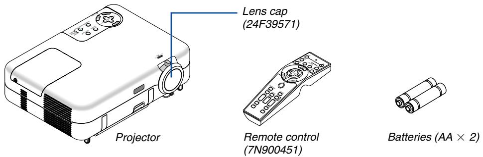
What's in the Box?
Make sure your box contains everything listed. If any pieces are missing, contact your dealer.
Please save the original box and packing materials if you ever need to ship your VT770 Projector.
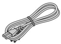
Power cable
(US: 7N080212)
(EU: 7N080005)
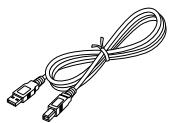
USB cable
(7N520013)
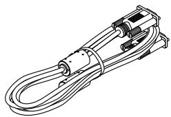
RGB signal cable
(7N520012)
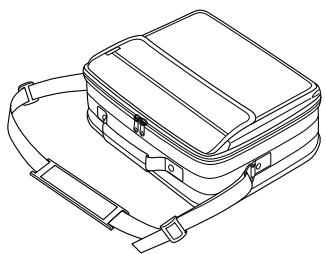
Soft carrying case
(24BS7311)
(7N8P4101)
(7N8P4111)
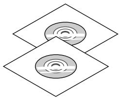
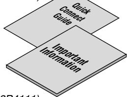
CD-ROM
- User's manual (7N950422)
- User Supportware (7N950431)
For North America only
Registration card
Limited warranty
For Europe only
Guarantee policy
Introduction to the Projector
This section introduces you to the VT770 Projector and describes key features and controls.
Congratulations on Your Purchase of the VT770 Projector
The VT770 is a sophisticated three panel LCD XGA projector that produces an enhanced display in less than an 8-pound (4kg) design. With the VT770 you will be able to project images up to 300" (measured diagonally). Enjoy crisp and sharp large screen display from your DVD player, VCR, satellite hookup, HDTV source, PC, Workstation or Macintosh computer (desktop or notebook) and images from your digital camera PC Card, compact flash memory or USB storage device. The VT770 provides for enhanced security options to help deter projector theft and provides for full projector control through RS232 support. With input and output flexibility, long lamp life and a full function remote, the VT770 lets you enjoy larger than life viewing from a compact and easy to setup and use projector.
Features you'll enjoy on the VT770:
Automatic vertical keystone correction for fast and easy application setup
- Built-in Wall Color Correction presets provide for adaptive color correction when projecting onto non-white screen material.
- 3D Reform™ enhanced image technology for increased projector versatility that provides for horizontal, vertical and diagonal keystone correction (allows for positioning the projector in off center locations in the room and still get aligned images)
- USB memory or PC card interfaces provide for computerless presentations
- Enhanced smart security settings for password protection, control panel lock, menu lock and PC card protection key to help prevent unauthorized access, adjustments and theft deterrence
UXGA compatible, XGA native resolution
Variable audio out control of external amplified speakers via the projector
- Extensive user adjustable picture and color management settings
- Core technologies - Advanced AccuBlend™, Advanced AutoSense™, VORTEX Technology Plus™ for highest quality of image display and ease of use
- Display 16:9 or 4:3 aspect ratio information and fill the screen
HDTV (1080i, 720p) and SDTV (480p, 480i) compatibility
- Digital photo viewer to display larger than life images from your digital cameras PC card, compact flash card or USB storage device
- Easy set up, use and operation
- Manual zoom and manual focus lens
- Eco-mode™ lamp technology for increased lamp life, reduced energy consumption and overall total cost of ownership savings
- Wireless remote control operation
External control via RS232
- NEC's exclusive Advanced AccuBlend intelligent pixel blending technology provides for extremely accurate image compression and HDTV (1920x1080 and 1280x720) display resolution*.
Supports most IBM VGA, SVGA, XGA, Macintosh, component signal (YCbCr/YPbPr) or other RGB signals within a horizontal frequency range of 15 to 100kHz and a vertical frequency range of 50 to 120Hz . This includes NTSC, NTSC4.43, PAL, PAL-M, PAL-N, PAL60 and SECAM standard video signals
NOTE: Composite video standards are as follows:
NTSC: U.S. TV standard for video in U.S. and Canada.
PAL: TV standard used in Western Europe.
PAL-N: TV standard used in Argentine, Paraguay and Uruguay.
PAL-M: TV standard used in Brazil.
PAL60: TV standard used for NTSC playback on PAL TVs.
SECAM: TV standard used in France and Eastern Europe.
NTSC4.43: TV standard used in Middle East countries.
1 Do not attempt to mount the projector on the ceiling yourself. To ensure proper operation and reduce the risk of bodily injury a qualified technician must install the projector. In addition, the ceiling must be strong enough to support the projector and the installation must be in accordance with any local building codes. Please consult your dealer for more information.
2 HDTV 1080i (1920 × 1080) and HDTV 720 p (1280 × 720) are displayed with NECs Advanced AccuBlend technology.
Thank you for your purchase of the NEC VT770 projector.
For additional information, please visit our website at:
US: http://www.necvisualsystems.com
Europe: http://www.nec-europe.com/
Global: http://www.nec-pj.com/
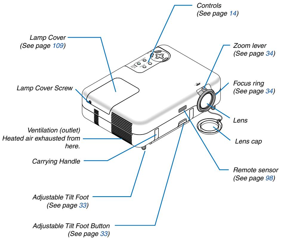
Part Names of the Projector
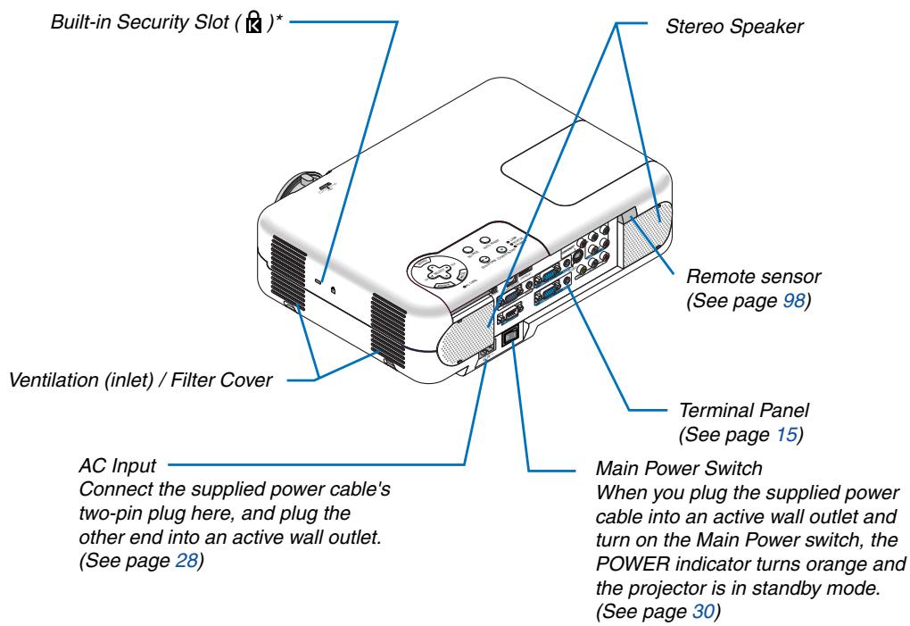
* This security slot supports the MicroSaver ® Security System. MicroSaver ® is a registered trademark of Kensington Microwave Inc. The logo is trademarked and owned by Kensington Microwave Inc.
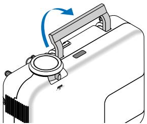
Carrying the Projector
Always carry your projector by the handle.
Ensure that the power cable and any other cables connecting to video sources are disconnected before moving the projector.
When moving the projector or when it is not in use, cover the lens with the lens cap.
Top Features
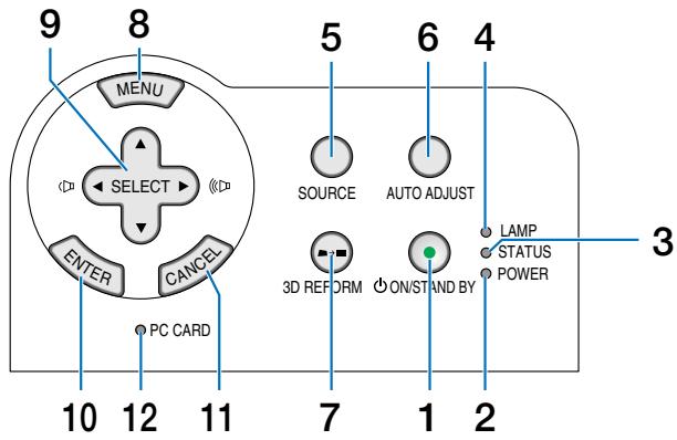
1. POWER Button (ON / STAND BY) ( ⊙ )
Use this button to turn the power on and off when the main power is supplied.
To turn on or off the projector, press and hold this button for a minimum of two seconds.
2. POWER Indicator
When this indicator is green, the projector is on; when this indicator is orange, it is in standby mode. See the Power Indicator section on page 113 for more details.
3. STATUS Indicator
If this light blinks red rapidly, it indicates that an error has occurred, the lamp cover is not attached properly or the projector has overheated.
If this light remains orange, it indicates that you have pressed a cabinet button while the Cabinet Button is locked. See the Status Indicator section on page 113 for more details.
4. LAMP Indicator
If this light blinks red rapidly, it's warning you that the lamp has reached the end of its usable life. After this light appears, replace the lamp as soon as possible (See page 109). If this is lit green continually, it indicates that the lamp mode is set to Eco. See the Lamp Indicator section on page 113 for more details.
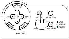
5. SOURCE Button
Use this button to select a video source such as a PC, VCR, DVD player or Viewer (PC card).
Press and release this button quickly to display the Source List.
Each time this button is pressed for a minimum of ONE second, the input source will change as follows:
Computer1 Computer2 Component Video S-Video Viewer Entry List Computer1 ... If no input signal is present, the input will be skipped.
6. AUTO ADJ. Button
Use this button to adjust Position-H/V and Pixel Clock/ Phase for an optimal picture (See page 37). Available for the RGB signal only.
7. 3D REFORM Button
Press this button to enter 3D Reform mode to correct the keystone (trapezoidal) distortion, and make the image square. See pages 35 and 44.
8. MENU Button
Displays the menu.
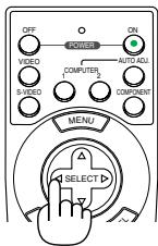
9. SELECT ▲▼▲ / Volume Buttons
: Use these buttons to select the menu of the item you wish to adjust.
: Use these buttons to change the level of a selected menu item.
A press of the button executes the selection. When no menus appear, these buttons work as a volume control.
When an image is magnified, the SELECT button moves the image.
10. ENTER Button
Executes your menu selection and activates items selected from the menu.
11. CANCEL Button
Pressing this button will return to the previous menu. While you are in the main menu, pressing this button will close the menu.
12. PC CARD Access Indicator
Lights while accessing a PC card.
Terminal Panel Features
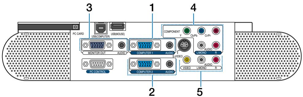
1. COMPUTER 1 Input Connector (Mini D-Sub 15 Pin)
Connect your computer or other analog RGB equipment such as IBM compatible or Macintosh computers. Use the supplied RGB cable to connect to your computer.
COMPUTER 1 AUDIO Input Mini Jack (Stereo Mini)
This is where you connect the audio output from your computer when connected to the COMPUTER 1 input. A commercially available audio cable is required.
2. COMPUTER 2 Input Connector (Mini D-Sub 15 Pin)
Connect your computer or other analog RGB equipment such as IBM compatible or Macintosh computers. Use the supplied RGB cable to connect to your computer.
This connector also supports SCART output signal.
The SCART cable is sold separately.
See page 24 for more details.
NOTE: The COMPUTER 2 Input does not support Plug & Play.
COMPUTER 2 AUDIO Input Mini Jack (Stereo Mini)
This is where you connect the audio output from your computer when connected to the COMPUTER 2 input. A commercially available audio cable is required.
3. MONITOR OUT Connector (Mini D-Sub 15 Pin)
You can use this connector to loop your computer image to an external monitor from the COMPUTER 1/2 or component video input source.
This connector also outputs a COMPUTER signal or component signal in Idle mode.
AUDIO OUT Mini Jack (Stereo Mini)
You can use this jack to output sound from the currently selected source (COMPUTER 1/2, COMPO- NENT,VIDEO or S-VIDEO).The current or last displayed source's audio will be sent to the audio output even in Idle mode.
Output sound level (volume, bass/treble and mute) can be adjusted in accordance with the sound level of the internal speaker.
Output sound level (volume, bass/treble and mute) cannot be adjusted in Idle mode.
Note that this cannot be used as a headphone jack. (When audio equipment is connected, the projector speaker is disabled.)
4. COMPONENT (Y, Cb/Pb, Cr/Pr) Input Connectors (RCA)
Connect component video outputs (Y/Cb/Cr, Y/Pb/Pr) of the external equipment such as DVD player.
NOTE: The "Y" connector accepts Video signal.
COMPONENT AUDIO Input Jacks R/L (RCA)
These are your left and right channel audio inputs for stereo sound from your DVD player or component equipment connected to COMPONENT Input Connectors.
5. VIDEO Input Connector (RCA)
Connect a VCR, DVD player, laser disc player, or document camera here to project video.
VIDEO/S-VIDEO AUDIO Input Jacks R/L (RCA)
These are your left and right channel audio inputs for stereo sound from a Video or S-Video source.
Terminal Panel Features
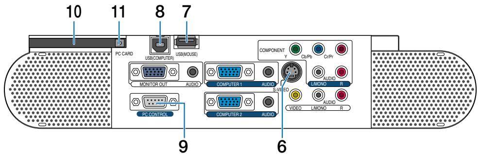
6. S-VIDEO Input Connector (Mini DIN 4 Pin)
Here is where you connect the S-Video input from an external source like a VCR.
NOTE: S-Video provides more vivid color and higher resolution than the traditional composite video format.
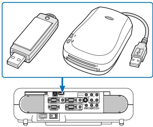
7. USB (MOUSE) Port (Type A)
Connect a commercially available USB mouse. You can operate the menu or Viewer with the USB mouse via this port.
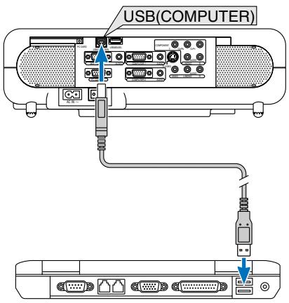
8. USB (COMPUTER) Port (Type B)
Connect this port to the USB port (type A) of your PC using the supplied USB cable. You can operate your computer's mouse functions from the remote control.
9. PC CONTROL Port (D-Sub 9 Pin)
Use this port to connect your PC to control your projector via a serial cable. This enables you to use your PC and serial communication protocol to control the projector. A commercially available RS232C cross cable is required to use this port. You can also control the projector by using Dynamic Image Utility 2.0 included on the supplied CD-ROM.
To do so you must first have Dynamic Image Utility 2.0 installed on your PC. If you are writing your own program, typical PC control codes are on page 121.
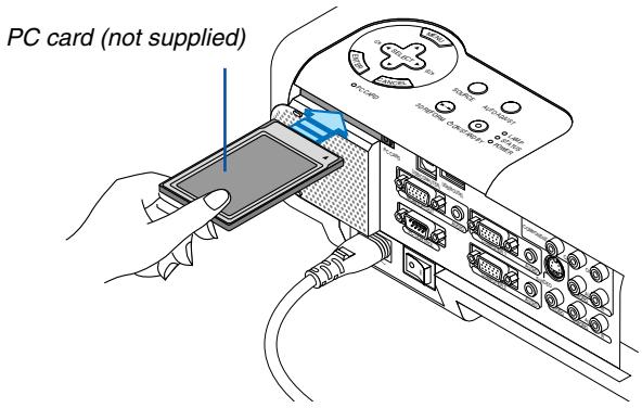
10. PC CARD Slot
Insert a PC card here.
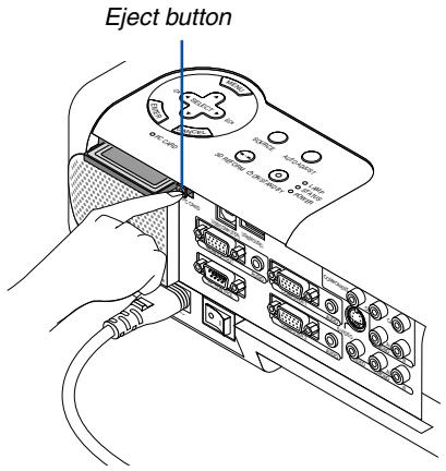
11. PC CARD Eject Button
Press to partially eject a PC card partially.
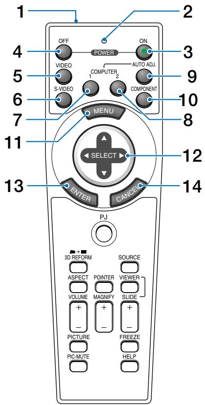
Part Names of the Remote Control
NOTE: If you are using a Macintosh computer, you can click either the CANCEL (right-click) or ENTER (left-click) button to activate the mouse.
- Infrared Transmitter
Direct the remote control toward the remote sensor on the projector cabinet.
- LED
Flashes when any button is pressed.
- POWER ON Button
When the main power is on, you can use this button to turn your projector on.
NOTE: To turn on the projector, press and hold the POWER ON button for a minimum of two seconds.
- POWER OFF Button
You can use this button to turn your projector off.
NOTE: To turn off the projector, press and hold the POWER OFF button for a minimum of two seconds.
5.VIDEO Button
Press this button to select a video source from a VCR, DVD player, laser disc player or document camera.
- S-VIDEO Button
Press this button to select an S-Video source from a VCR.
- COMPUTER 1 Button
Press this button to select COMPUTER 1 input.
- COMPUTER 2 Button
Press this button to select COMPUTER 2 input.
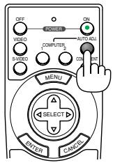
- AUTO ADJ. Button
Use this button to adjust an RGB source for an optimal picture. See page 37.
- COMPONENT Button
Press this button to select a video source from component equipment connected to your COMPONENT input.
- MENU Button
Displays the menu for various settings and adjustments.
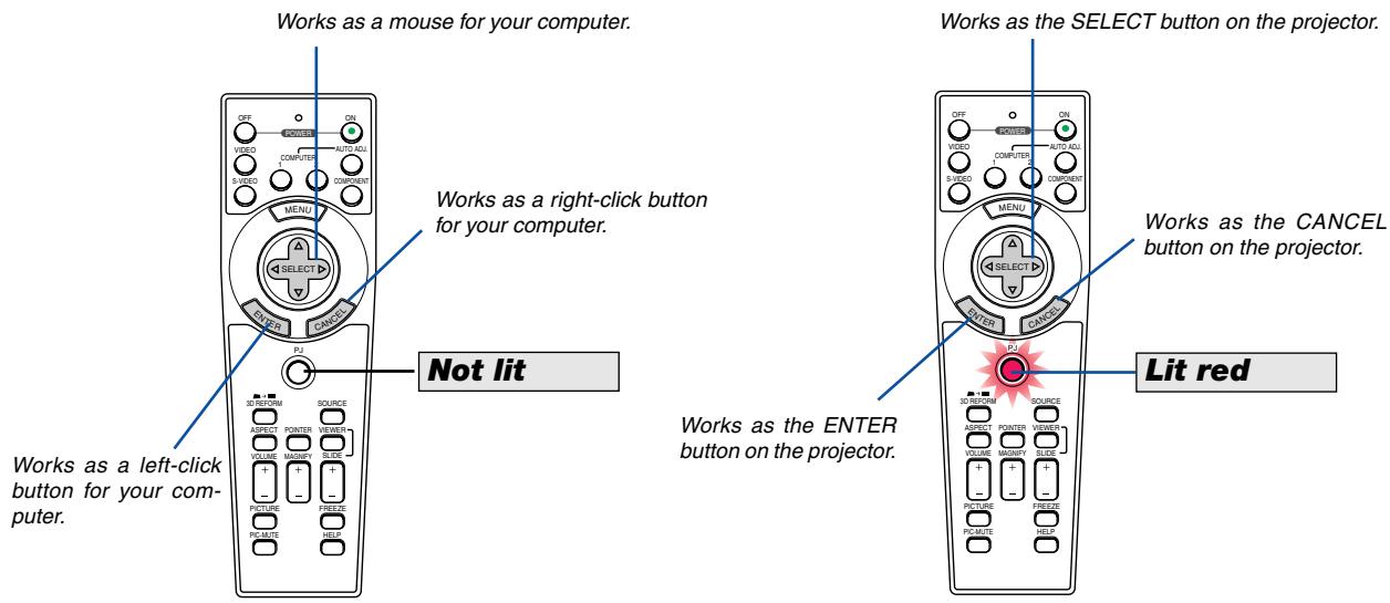
- SELECT (Mouse) Button
When you are in the Computer mode, these buttons work as a computer mouse.
When you are in the Projector mode, which is indicated by lighting the PJ button. See page 40.
: Use these buttons to select the menu of the item you wish to adjust.
Use these buttons to change the level of a selected menu item. A press of the button executes the selection. When no menus appear, these buttons work as a volume control.
When an image is magnified, the SELECT button moves the image.
- ENTER (Left Click) Button
When you are in the Computer mode, this button works as the mouse left button. When this button is pressed and held for a minimum of 2 seconds, the drag mode is set. When you are in the Projector mode, which is indicated by lighting the PJ button: Use this button to enter your menu selection. It works the same way as the ENTER button on the cabinet. See page 40.
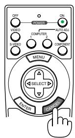
- CANCEL (Right Click) Button
When you are in the Computer mode, this button works as the mouse right button. When you are in the Projector mode, which is indicated by lighting the PJ button: It works the same way as the CANCEL button on the cabinet. See page 40.
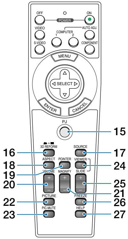
15.PJ Button
Press this button to switch the SELECT, CANCEL, and ENTER buttons between the Projector mode (lit red) and the Computer mode.
Press this button or any one of the POWER ON/OFF, MENU, 3D REFORM, ASPECT, POINTER, HELP, MAGNIFY, VIEWER or PICTURE buttons to switch to the Projector mode and the PJ button lights red. To switch back to the Computer mode, press the PJ button again. See page 40.
16.3D REFORM Button
Press this button to enter 3D Reform to correct the keystone (trapezoidal) distortion, and make the image square. See pages 35 and 44.
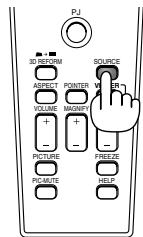
17. SOURCE Button
Use this button to select a video source such as a PC, VCR, DVD player or Viewer (PC card).
Press and release this button quickly to display the Source List.
Each time this button is pressed for a minimum of ONE second, the input source will change as follows:
Computer1 Computer2 Component Video S-Video Viewer Entry List Computer1 ...
If no input signal is present, the input will be skipped.
18. ASPECT Button
Press this button to display the Aspect Ratio select screen. See page 82.
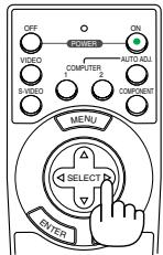
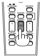
19. POINTER Button
Press this button to display one of the nine pointers; press again to hide the pointer. You can move your pointer icon to the area you want on the screen using the SELECT button. See page 41.
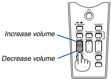
20. VOLUME (+)(-) Button
Press (+) to increase the volume and (-) to decrease it.
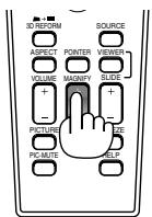
21. MAGNIFY (+) (-) Button
Use this button to adjust the image size up to 400% . The image is magnified about the center of the screen. See page 41.
22. PICTURE Button
Press this button to display the Picture window. Each time this button is pressed, the option will be changed. See page 78.
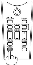
23. PIC-MUTE Button
This button turns off the image and sound for a short period of time.
Press again to restore the image and sound.
24. VIEWER Button
Press this button to select the Viewer source.
25. SLIDE (+)(-) Button
Press (+) to select the next folder or slide and (-) to select the previous folder or slide. See page 58.
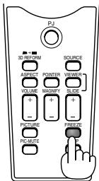
26. FREEZE Button
This button will freeze a picture. Press again to resume motion.
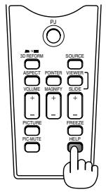
27. HELP Button
Provides suitable HELP information.
NOTE: The default is the Computer mode, which allows you to use the SELECT, CANCEL, and ENTER buttons as your computer mouse. When the POWER ON/OFF, MENU, 3D REFORM, ASPECT, POINTER, HELP, MAGNIFY, VIEWER or PICTURE button is pressed, the PJ button lights red to indicate that you are in the Projector mode. If no buttons are pressed within 60 seconds, the light goes out and the Projector mode is canceled.
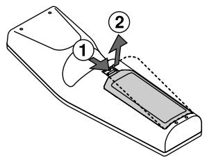
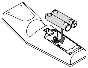
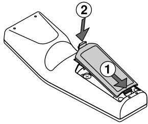
Battery Installation
1 Remove the battery cover.
2 Remove both old batteries and install new ones (AA). Ensure that you have the batteries' polarity (+/-) aligned correctly.
3 Slip the cover back over the batteries until it snaps into place. Do not mix different types of batteries or new and old batteries.
Note on Remote Control Operation
If you press and hold the SELECT button while installing new batteries, the remote control may fail to work properly.
Should this happen, remove the batteries and then install them again without touching the SELECT button.
Remote Control Precautions
- Handle the remote control carefully.
- If the remote control gets wet, wipe it dry immediately.
- Avoid excessive heat and humidity.
- If you will not be using the remote control for a long time, remove the batteries.
- Do not place the batteries upside down.
- Do not use new and old batteries together, or use different types of batteries together.
Operating Range for Wireless Remote Control
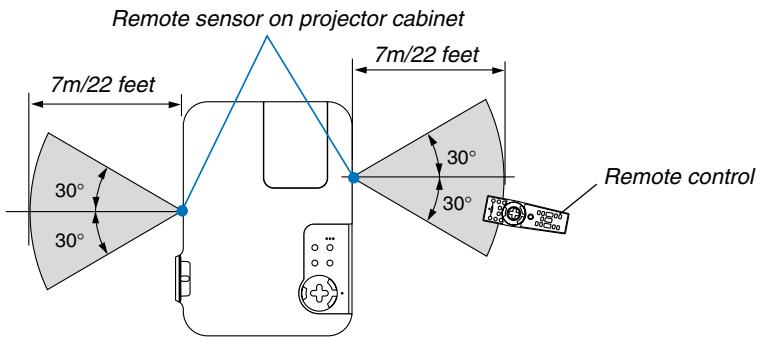
- The infrared signal operates by line-of-sight up to a distance of about 22 feet/7 m and within a 60-degree angle of the remote sensor on the projector cabinet.
- The projector will not respond if there are objects between the remote control and the sensor, or if strong light falls on the sensor.
Weak batteries will also prevent the remote control from properly operating the projector.
2
Installation and Connections
Setting Up the Screen and the Projector 21
Selecting a Location 21
Throw Distance and Screen Size 22
2 Making Connections 23
Enabling the computer's external display 23
Connecting Your PC or Macintosh Computer 23
To connect SCART output (RGB) 24
Connecting an External Monitor 25
Connecting Your DVD Player with Component Output 26
Connecting Your VCR or Laser Disc Player 27
Connecting the Supplied Power Cable 28
This section describes how to set up your projector and how to connect PCs, video and audio sources.
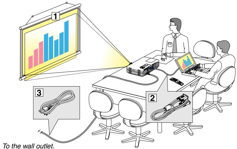
Your projector is simple to set up and use. But before you get started, you must first:
1 Set up a screen and the projector.
2 Connect your computer or video equipment to the projector. See pages 23 - 27.
3 Connect the supplied power cable. See page 28.
NOTE: Ensure that the power cable and any other cables are disconnected before moving the projector. When moving the projector or when it is not in use, cover the lens with the lens cap.
1 Setting Up the Screen and the Projector
Selecting a Location
The further your projector is from the screen or wall, the larger the image. The minimum size the image can be is approximately 25^ (0.64 m) measured diagonally when the projector is roughly 31.5 inches (0.8 m) from the wall or screen. The largest the image can be is 300^ (7.6 m) when the projector is about 393.7 inches (10 m) from the wall or screen. Use the drawing below as a guide.
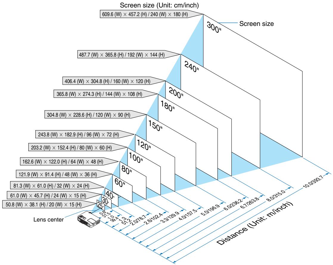
Throw Distance and Screen Size
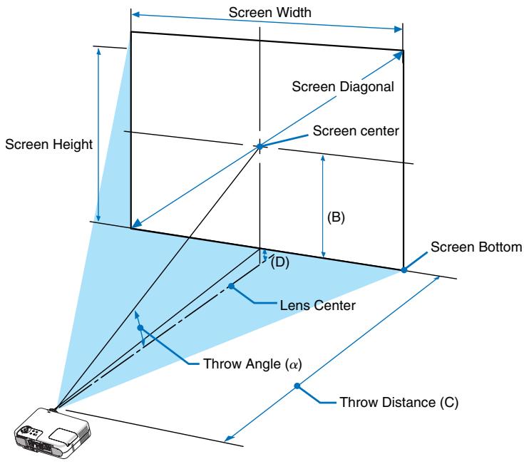
The following shows the proper relative positions of the projector and screen. Refer to the table to determine the position of installation.
Distance Chart
B = Vertical distance between lens center and screen center
C = Throw distance
D = Vertical distance between lens center and bottom of screen (top of screen for ceiling application)
= Throw angle
NOTE: Distances may vary +/-5%.
| Screen Size | B | C Wide – Tele | D | α Wide – Tele | |||
| Diagonal | Width | Height | |||||
| inch | inch | inch | inch | inch | inch | degree | |
| 25 | 20.0 | 15.0 | 6.0 | 28.0 - 34.0 | -2.0 | 12.1 - 9.9 | |
| 30 | 24.0 | 18.0 | 7.0 | 34.0 - 41.0 | -2.0 | 12.0 - 9.9 | |
| 40 | 32.0 | 24.0 | 10.0 | 46.0 - 56.0 | -2.0 | 11.8 - 9.7 | |
| 60 | 48.0 | 36.0 | 14.0 | 70.0 - 85.0 | -4.0 | 11.7 - 9.6 | |
| 67 | 54.0 | 40.0 | 16.0 | 78.0 - 95.0 | -4.0 | 11.6 - 9.6 | |
| 72 | 58.0 | 43.0 | 17.0 | 84.0 - 102.0 | -4.0 | 11.6 - 9.6 | |
| 80 | 64.0 | 48.0 | 19.0 | 94.0 - 114.0 | -5.0 | 11.6 - 9.6 | |
| 84 | 67.0 | 50.0 | 20.0 | 98.0 - 120.0 | -5.0 | 11.6 - 9.6 | |
| 90 | 72.0 | 54.0 | 22.0 | 106.0 - 128.0 | -5.0 | 11.6 - 9.6 | |
| 100 | 80.0 | 60.0 | 24.0 | 118.0 - 143.0 | -6.0 | 11.5 - 9.6 | |
| 120 | 96.0 | 72.0 | 29.0 | 141.0 - 172.0 | -7.0 | 11.5 - 9.5 | |
| 150 | 120.0 | 90.0 | 36.0 | 177.0 - 215.0 | -9.0 | 11.5 - 9.5 | |
| 180 | 144.0 | 108.0 | 43.0 | 213.0 - 258.0 | -11.0 | 11.5 - 9.5 | |
| 200 | 160.0 | 120.0 | 48.0 | 237.0 - 287.0 | -12.0 | 11.4 - 9.5 | |
| 220 | 176.0 | 132.0 | 53.0 | 261.0 - 316.0 | -13.0 | 11.4 - 9.5 | |
| 240 | 192.0 | 144.0 | 58.0 | 285.0 - 345.0 | -14.0 | 11.4 - 9.5 | |
| 260 | 208.0 | 156.0 | 62.0 | 309.0 - 374.0 | -16.0 | 11.4 - 9.5 | |
| 280 | 224.0 | 168.0 | 67.0 | 333.0 - 403.0 | -17.0 | 11.4 - 9.5 | |
| 300 | 240.0 | 180.0 | 72.0 | 356.0 - 431.0 | -18.0 | 11.4 - 9.5 | |
WARNING
- Installing your projector on the ceiling must be done by a qualified technician. Contact your NEC dealer for more information.
- Do not attempt to install the projector yourself.
- Only use your projector on a solid, level surface. If the projector falls to the ground, you can be injured and the projector severely damaged.
- Do not use the projector where temperatures vary greatly. The projector must be used at temperatures between 32^ (0^) and 95^ (35^) .
- Do not expose the projector to moisture, dust, or smoke. This will harm the screen image.
| Screen Size | B | C Wide – Tele | D | α Wide – Tele | |||
| Diagonal | Width | Height | |||||
| mm | mm | mm | mm | mm | mm | degree | |
| 635 | 508 | 381 | 152 | 710 - 870 | -38 | 12.1 - 9.9 | |
| 762 | 610 | 457 | 183 | 860 - 1050 | -46 | 12.0 - 9.9 | |
| 1016 | 813 | 610 | 244 | 1170 - 1420 | -61 | 11.8 - 9.7 | |
| 1524 | 1219 | 914 | 366 | 1770 - 2160 | -91 | 11.7 - 9.6 | |
| 1702 | 1361 | 1021 | 408 | 1990 - 2410 | -102 | 11.6 - 9.6 | |
| 1829 | 1463 | 1097 | 439 | 2140 - 2600 | -110 | 11.6 - 9.6 | |
| 2032 | 1626 | 1219 | 488 | 2380 - 2890 | -122 | 11.6 - 9.6 | |
| 2134 | 1707 | 1280 | 512 | 2500 - 3040 | -128 | 11.6 - 9.6 | |
| 2286 | 1829 | 1372 | 549 | 2680 - 3260 | -137 | 11.6 - 9.6 | |
| 2540 | 2032 | 1524 | 610 | 2990 - 3620 | -152 | 11.5 - 9.6 | |
| 3048 | 2438 | 1829 | 732 | 3590 - 4360 | -183 | 11.5 - 9.5 | |
| 3810 | 3048 | 2286 | 914 | 4500 - 5460 | -229 | 11.5 - 9.5 | |
| 4572 | 3658 | 2743 | 1097 | 5410 - 6560 | -274 | 11.5 - 9.5 | |
| 5080 | 4064 | 3048 | 1219 | 6020 - 7290 | -305 | 11.4 - 9.5 | |
| 5588 | 4470 | 3353 | 1341 | 6630 - 8030 | -335 | 11.4 - 9.5 | |
| 6096 | 4877 | 3658 | 1463 | 7230 - 8760 | -366 | 11.4 - 9.5 | |
| 6604 | 5283 | 3962 | 1585 | 7840 - 9490 | -396 | 11.4 - 9.5 | |
| 7112 | 5690 | 4267 | 1707 | 8450 - 10230 | -427 | 11.4 - 9.5 | |
| 7620 | 6096 | 4572 | 1829 | 9050 - 10960 | -457 | 11.4 - 9.5 | |
- Ensure that you have adequate ventilation around your projector so heat can dissipate. Do not cover the vents on the side of the projector.
Reflecting the Image
Using a mirror to reflect your projector's image enables you to enjoy a much larger image. Contact your NEC dealer if you need a mirror. If you're using a mirror and your image is inverted, use the MENU and SELECT buttons on your projector cabinet or your remote control to correct the orientation. See page 86.
Making Connections
NOTE: When using with a notebook PC, be sure to connect between the projector and the notebook PC before turning on the power to the notebook PC. In most cases signal cannot be output from RGB output unless the notebook PC is turned on after connecting with the projector.
- If the screen goes blank while using your remote control, it may be the result of the computer's screen-saver or power management software.
- If you accidentally hit the POWER button on the remote control, wait 60 seconds and then press the POWER button again to resume.
Enabling the computer's external display
Displaying an image on the notebook PC's screen does not necessarily mean it outputs a signal to the projector. When using a PC compatible laptop, a combination of function keys will enable/disable the external display. Usually, the combination of the 'Fn" key along with one of the 12 function keys gets the external display to come on or off. For example, NEC laptops use Fn + F3, while Dell laptops use Fn + F8 key combinations to toggle through external display selections.
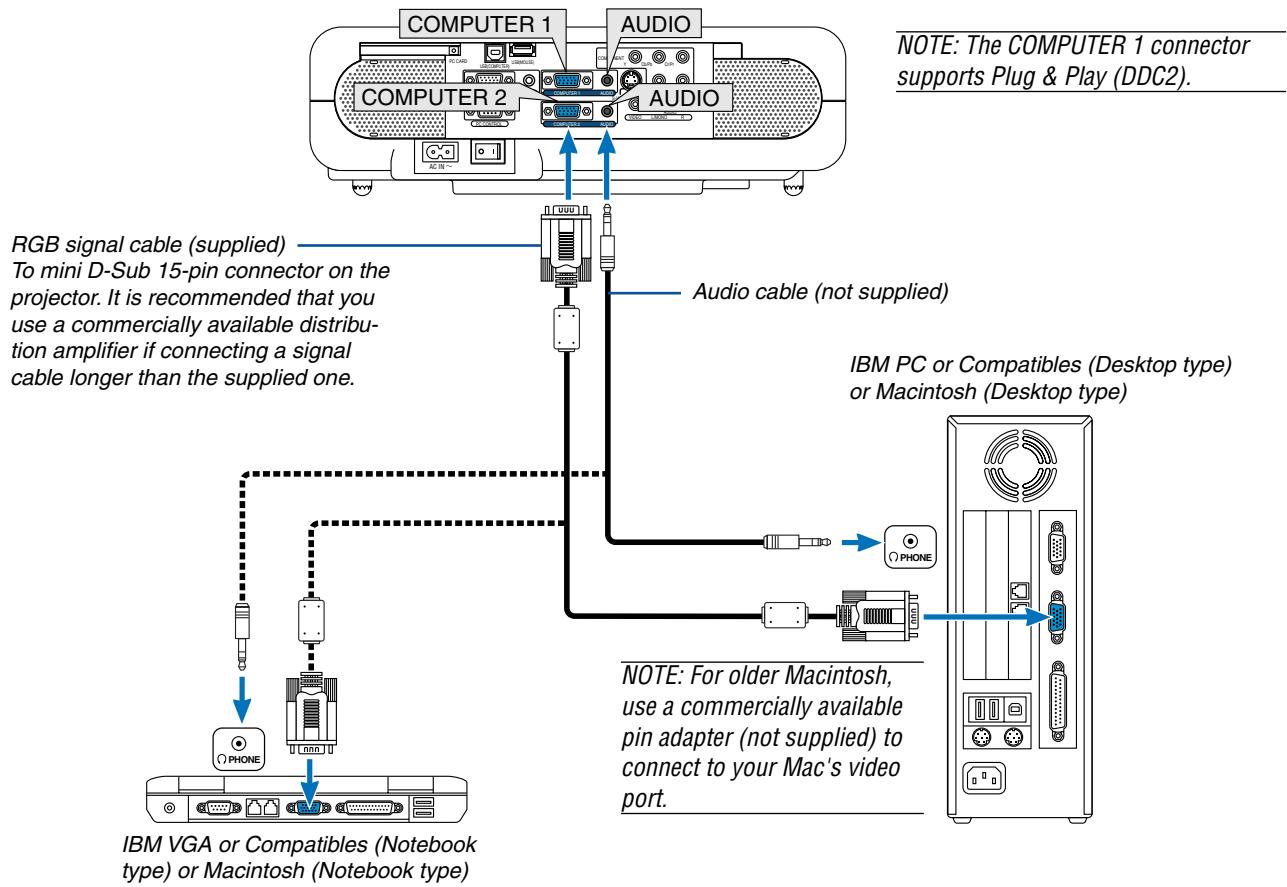
Connecting Your PC or Macintosh Computer
Connecting your PC or Macintosh computer to your projector will enable you to project your computer's screen image for an impressive presentation.
To connect to a PC or Macintosh, simply:
- Turn off the power to your projector and computer.
- Use the supplied signal cable to connect your PC or Macintosh to the projector.
- Connect the supplied power cable. See page 28.
- Turn on the projector and the computer.
- If the projector goes blank after a period of inactivity, it may be caused by a screen saver installed on the computer you've connected to the projector.
NOTE: The VT770 is not compatible with video decoded outputs of either the NEC ISS-6020 and ISS-6010 switchers.
NOTE: An image may not be displayed correctly when a Video or S-Video source is played back via a commercially available scan converter.
This is because the projector will process a video signal as a computer signal at the default setting. In that case, do the following.
- When an image is displayed with the lower and upper black portion of the screen or a dark image is not displayed correctly: Project an image to fill the screen and then press the AUTO ADJ button on the remote control or the AUTO ADJUST button on the projector cabinet.
- When noise appears on the sides of the screen: Use the Overscan feature to display the image correctly. Be sure to change the Overscan to 0% before pressing the AUTO ADJ or AUTO ADJUST button, otherwise an image may be displayed with its sides cut off.
To connect SCART output (RGB)
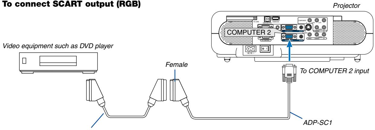
Commercially available SCART cable
Before connections: An exclusive SCART adapter (ADP-SC1) and a commercially available SCART cable are required for this connection.
NOTE: Audio signal is not available for this connection.
- Turn off the power to the projector and your video equipment.
- Use the NEC ADP-SC1 SCART adapter and a commercially available SCART cable to connect the RGB input of your projector and a SCART output (RGB) of your video equipment.
- Connect the supplied power cable. See page 28.
- Turn on the power to the projector and your video equipment.
- Use the COMPUTER 2 button on the remote control to select the COMPUTER 2 input.
- Press the MENU button on the remote control to display the menu.
- From the menu, select [Setup] [Page3] [Signal Select] [Computer 2] [Scart]. SCART is a standard European audio-visual connector for TVs, VCRs and DVD players. It is also referred to as Euro-connector.
NOTE: The ADP-SC1 SCART adapter is obtainable from your NEC dealer in Europe. Contact your NEC dealer in Europe for more information.
Connecting an External Monitor
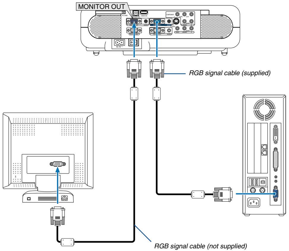
You can connect a separate, external monitor to your projector to simultaneously view on a monitor the RGB analog image you're projecting.
To do so:
- Turn off the power to your projector, monitor and computer.
- Use a 15-pin cable to connect your monitor to the MONITOR OUT (Mini D-Sub 15 pin) connector on your projector.
- Connect the supplied power cable. See page 28.
- Turn on the projector, monitor and the computer.
NOTE:
- The MONITOR OUT connector outputs RGB signal during Idle mode. When the projector goes into standby mode, the image on an external monitor disappears for a moment.
- When the projector is in the standby mode, the image may not be correctly displayed while the cooling fans are running immediately after turning on or off the power.
- Daisy chain connection is not possible.
Connecting Your DVD Player with Component Output
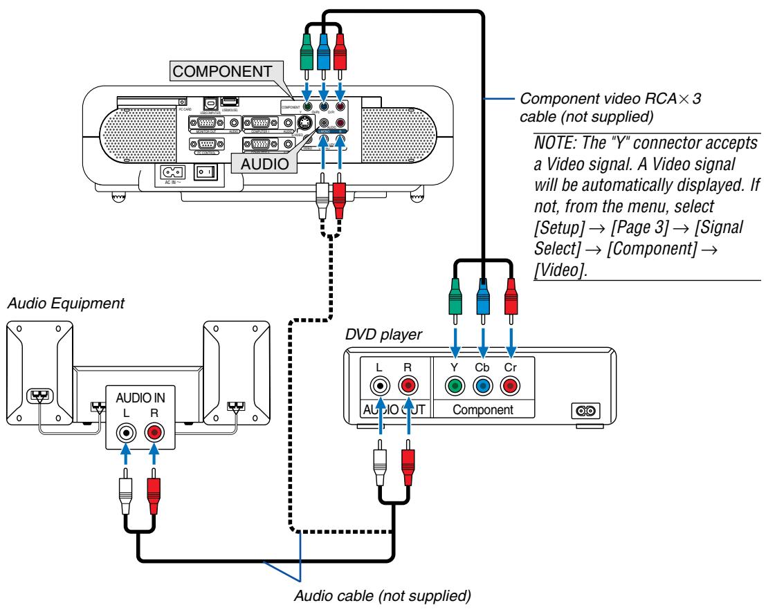
You can connect your projector to a DVD player with component output or Video output. To do so, simply:
NOTE: For a DVD player without component video (Y,Cb,Cr/Y, Pb, Pr) output, use an S-Video cable (not provided) to connect an S-Video output of the DVD player to the S-VIDEO input of the projector.
- Turn off the power to your projector and DVD player.
- If your DVD player has the component video (Y,Cb,Cr/Y, Pb, Pr) output, use a commercially available component video cable (RCA× 3) to connect your DVD player to the COMPONENT input connectors on the projector.
Use an audio cable (not supplied) to connect the audio from your DVD player to your audio equipment (if your DVD player has this capability). Be careful to keep your right and left channel connections correct for stereo sound.
- Connect the supplied power cable. See page 28.
- Turn on the projector and DVD player.
NOTE: Refer to your DVD player's owner's manual for more information about your DVD player's video output requirements.
Connecting Your VCR or Laser Disc Player
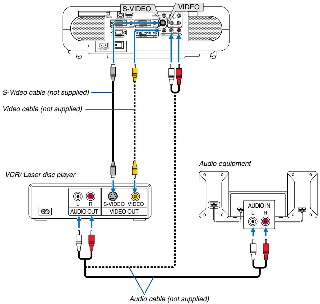
Use an RCA or S-Video cable (not provided) to connect the video and use RCA cables (not provided) to connect the audio from your VCR, laser disc player or document camera to your projector.
To make these connections, simply:
- Turn off the power to the projector and VCR, laser disc player or document camera.
- Connect one end of an RCA cable to the video output (or one end of an S-Video cable to the S-Video output connector) on the back of your VCR or laser disc player, connect the other end to the appropriate video input on your projector. Connect one end of a pair RCA cables (not supplied) to the audio output on the back of your VCR or laser disc player, connect the other end to your audio equipment or to the appropriate audio input on the projector.
Be careful to keep the right and left channel connections correct for stereo sound.
- Connect the supplied power cable. See page 28.
- Turn on the projector and the VCR or laser disc player.
NOTE: Refer to your VCR or laser disc player owner's manual for more information about your equipment's video output requirements.
NOTE: An image may not be displayed correctly when a Video or S-Video source is played back in fast-forward or fast-rewind via a scan converter.
Connecting the Supplied Power Cable
Connect the supplied power cable to the projector.
First connect the supplied power cable's two-pin plug to the AC IN of the projector, and then connect the other plug of the supplied power cable in the wall outlet.
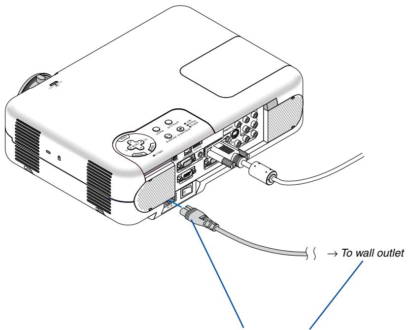
Make sure that the prongs are fully inserted into both the AC IN and the wall outlet.
3
Projecting an Image
(Basic Operation)
1 Turning on the Projector 30
2 Selecting a Source 32
3 Adjusting the Picture Size and Position 33
4 Correcting Keystone Distortion 35
Optimizing RGB Picture Automatically 37
6 Turning Up or Down Volume 37
7 Turning off the Projector 38
8 After Use 38
This section describes how to turn on the projector and to project a picture onto the screen.
1 Turning on the Projector
NOTE:
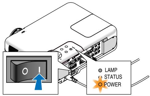
- The projector has two power switches: a main power switch and a POWER (ON/STAND BY) button (POWER ON and OFF on the remote control).
- When plugging in or unplugging the supplied power cable, make sure that the main power switch is pushed to the off (O) position. Failure to do so may cause damage to the projector.
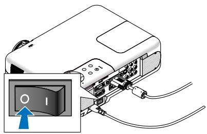
To turn on the main power to the projector, press the Main Power switch to the on position (I).
- If you turn on the projector immediately after cooling down, it may take longer than usual for the lamp to light.
After you turn on your projector, ensure that the computer or video source is turned on and that your lens cap is removed.
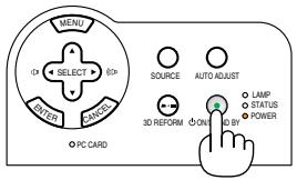
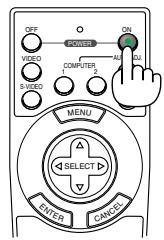
Only after you press the POWER (ON/STAND BY) button on the projector cabinet or POWER ON button on the remote control for a minimum of 2 seconds will the power indicator turn to green and the projector become ready to use.
NOTE: When no signal is available, a blue, black or logo screen is displayed.
When the projector displays a blue or a black screen (not logo), the Eco mode will be automatically selected in "Lamp Mode."
Note on Startup screen (Menu Language Select screen)
When you first turn on the projector, you will get the Startup screen. This screen gives you the opportunity to select one of the 19 menu languages.
To select a menu language, follow these steps:
1. Use the SELECT or button to select one of the 19 languages for the menu.
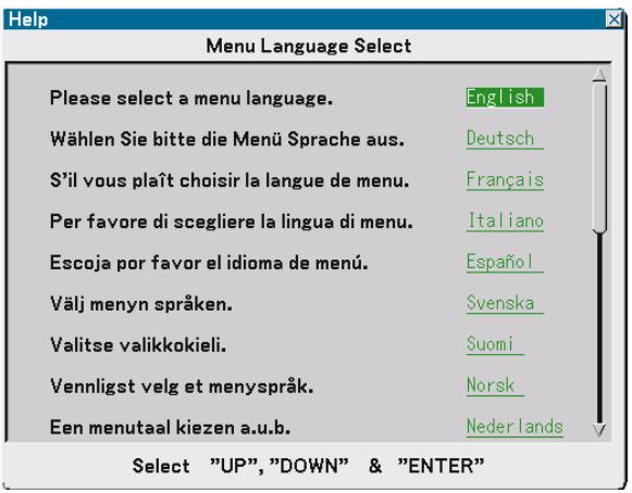
2. Press the ENTER button to execute the selection.
After this has been done, you can proceed to the menu operation.
If you want, you can select the menu language later.
See "Language" on page 86.
NOTE: Immediately after turning on the projector, screen flicker may occur. This is not a fault. Wait 3 to 5 minutes until the lamp lighting is stabilized.
When the Lamp mode is set to Eco, the Lamp indicator will light green.
If one of the following things happens, the projector will not turn on.
- If the internal temperature of the projector is too high, the projector detects abnormal high temperature. In this condition the projector will not turn on to protect the internal system. If this happens, wait for the projector's internal components to cool down.
- When the lamp reaches its end of usable life, the projector will not turn on. If this happens, replace the lamp. See page 109.
- If the lamp fails to light, and if the STATUS indicator flashes on and off in a cycle of six times, wait a full minute and then turn on the power.
Selecting a Source
Selecting the computer or video source
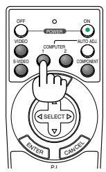
Using the Remote Control
Press any one of the COMPUTER 1/2, COMPONENT,VIDEO, S-VIDEO or VIEWER buttons.
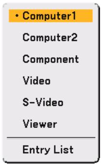
Selecting from Source List
Press and quickly release the SOURCE button on the projector cabinet to display the Source list. Each time the SOURCE button is pressed, the input source will change as follows: "Computer 1/2", "Component" (DVD player), "Video" (VCR or laser disc player), "S-Video" or "Viewer" (slides on a PC card). To display the selected source, press the ENTER button.
Detecting the Signal Automatically
Press and hold the SOURCE button for a minimum of 1 second, the projector will search for the next available input source. Each time you press and hold the SOURCE button for a minimum of 1 second, the input source will change as follows:
Computer1 Computer2 Component Video S-Video Viewer Computer1 ...
If no input signal is present, the input will be skipped. When the input source you wish to project is displayed, release the button.

Adjusting the Picture Size and Position
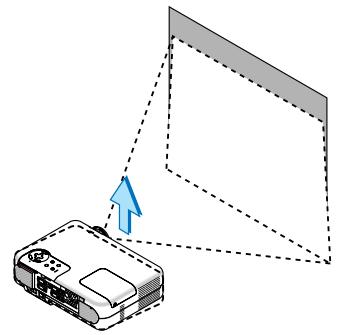
Place your projector on a flat level surface and ensure that the projector is square to the screen.
Lift the front edge of the projector to center the image vertically.
If the projected image does not appear square to the screen then use the Keystone feature for proper adjustment. See pages 35 and 44.
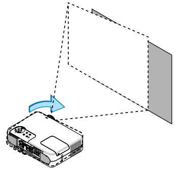
Rotate the projector's front right or left (to the right in this example) to center the image horizontally on the screen.
Adjust the Tilt Foot
- Lift the front edge of the projector.
- Push up and hold the Adjustable Tilt Foot Button on the front of the projector to extend the adjustable tilt feet (maximum height: 30mm/1.2").
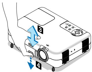
- Lower the front of the projector to the desired height.
- Release the Adjustable Tilt Foot Button to lock the Adjustable tilt foot.
There is approximately 10 degrees of up and down adjustment for the front of the projector.
Adjusting the height of a projected image or changing projection angle will run the Auto Keystone correction function to quickly correct the vertical distortion. The "Keystone" screen will be displayed.
For operating the "Keystone" screen, see "Correcting Vertical Keystone Distortion" on page 35.
NOTE: Your "Keystone" correction data can be reset by pressing and holding the 3D REFORM button for a minimum of 2 seconds.
CAUTION
Do not use the tilt-foot for purposes other than originally intended.
Misuses such as gripping the tilt-foot or hanging on the wall can cause damage to the projector.
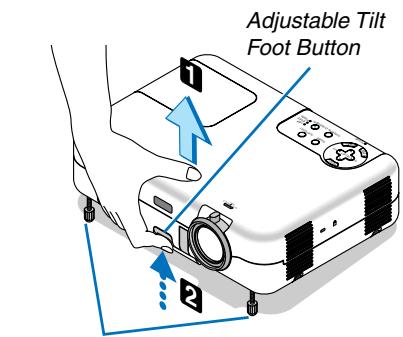
Adjustable Tilt Foot
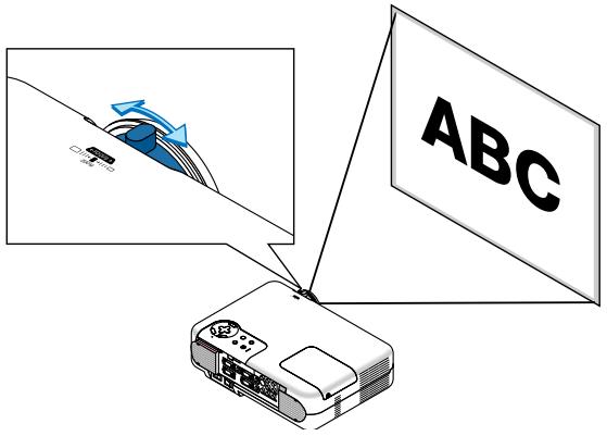
Zoom
Use the ZOOM lever to finely adjust the image size on the screen.
You can use the ZOOM lever to enlarge or reduce an image size.
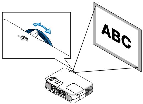
Focus
Use the FOCUS ring to obtain the best focus.
4 Correcting Keystone Distortion
Auto Keystone Correction
The Auto Keystone correction feature will correct vertical distortion of a projected image on the screen. No special operation required. Just put the projector on a flat surface.
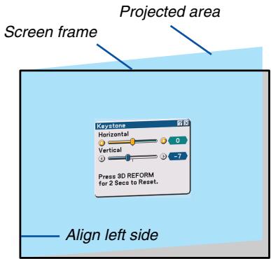
Manual Keystone Correction
You can also correct keystone distortion manually.
To do so:
1. Extend the Adjustable Tilt Foot to adjust the height of a projected image. See page 33.
The Keystone screen will be displayed on the screen.
- If the Keystone screen disappears, press the MENU button or ENTER button once to display the Keystone screen again.
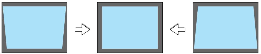
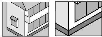
2. Align the left (or right) side of the screen with the left (or right) side of the projected image.
- Use the shorter side of the projected image as the base.
- In the right example, use the left side as the base.
NOTE: When "Manual" is selected in "Keystone" from the menu, project an image adjusting projector position so that the screen is smaller than the area of the projected image. See page 87 for selecting "Manual" in "Keystone".
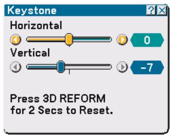
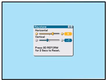
3. Use the SELECT or button to select "Horizontal".
Perform the keystone correction.
4. If the right and left sides of the projected image are not parallel to each other, use the SELECT button to select "Vertical" and use the SELECT button.
Fine adjust so that both sides are parallel to each other.
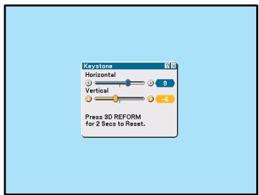
- Repeat steps 3 and 4 to correct keystone distortion.
- After completing Keystone correction, press the ENTER button.
The Keystone screen will disappear.
- To perform Keystone correction again, press the 3D REFORM button to display the Keystone screen and repeat above steps 1 to 6.

NOTE:
- Turning on the projector will reset the previous correction setting values if the projection angle is changed from the last use. If the projection angle is the same as in the last use, the previous correction setting values are retained in the memory. To use the previous correction setting values after changing projection angle, select "Manual" in "Keystone" from the menu. See page 87. To return the 3D Reform correction setting values to the factory preset, press and hold the 3D REFORM button for a minimum of 2 seconds.
Each time the 3D REFORM button is pressed, the item will change as follows: Keystone Cornerstone None Keystone ... For information on "Cornerstone", see "Correcting Horizontal and Vertical Keystone Distortion (Cornerstone) on page 44. - You can zoom in or out, while keeping an image that was corrected using "Keystone", without again having to make those adjustments.
Optimizing RGB Picture Automatically
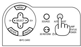
Adjusting the Image Using Auto Adjust
Optimizing an RGB image automatically.
Press the Auto Adjust button to optimize an RGB image automatically.
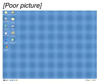

[Normal picture]
Press the Auto Adjust button to fine-tune the computer image or to remove any vertical banding that might appear and to reduce video noise, dot interference or cross talk (this is evident when part of your image appears to be shimmering). This function adjusts the clock frequencies that eliminate the horizontal banding in the image. This function also adjusts the clock phase to reduce video noise, dot interference or cross talk. (This is evident when part of your image appears to be shimmering.)
This adjustment may be necessary when you connect your computer for the first time.
NOTE:
- Some signals may not be displayed correctly or take time.
- The Auto Adjust function does not work for component or video signals.
- If the Auto Adjust operation cannot optimize the RGB signal, try to adjust Clock and Phase manually. See page 84.
Turning Up or Down Volume
Sound level from the speaker and the AUDIO OUT jack (Stereo mini) on the projector can be adjusted.
7 Turning off the Projector
To turn off the projector:
First, press the POWER (ON/STAND BY) button on the projector cabinet or the POWER OFF button on the remote control for a minimum of two seconds.
The power indicator will glow orange. After the projector turns off, the cooling fans keep operating for 10 seconds (Cooling-off time).
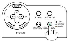
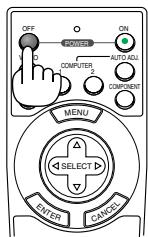
Secondly, turn off the Main Power switch. The power indicator will go out.
Finally unplug the power cable.
CAUTION
Do not unplug the power cable from the wall outlet or do not turn off the main power under any one of the following circumstances.
Doing so can cause damage to the projector:
- While the Hour Glass icon appears.
- While the cooling fans are running. (The cooling fans continue to work for 10 seconds after the projector is turned off).
After Use
Preparation: Make sure that the projector is not turned on.
- Unplug the power cable.
- Disconnect any other cables.
- Retract adjustable tilt feet if extended.
- Cover the lens with the lens cap.
- Put the projector and its accessories in the supplied soft carrying case.
4
Convenient Features
Switching Operation Mode between Computer and Projector 40
Turning Off the Image and Sound 40
3 Freezing a Picture 40
4 Using the Pointer 41
5 Enlarging and Moving a Picture 41
Getting the On-line Help 42
Using a USB Mouse 42
8 Using the Remote Mouse Function 43
Correcting Horizontal and Vertical Keystone Distortion (Cornerstone) 44
10 Making Freehand Drawings on a Projected Image (ChalkBoard) 47
11 Storing Images Displayed on the Projector on the PC card or USB Memory (Capture) 48
Preventing the Unauthorized Use of the Projector .... 49
Using a USB Memory Device or USB Memory Card Reader 54
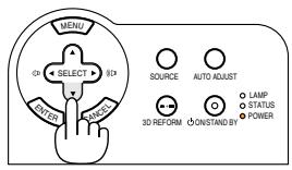
Switching Operation Mode between Computer and Projector
The three shaded buttons shown on the drawing work as a computer mouse in the Computer mode. In the Computer mode the PJ button is not lit.
- When the MENU button is pressed, the PJ button lights red to indicate that you are in the Projector mode, which allows the projector menu operation using the three buttons.
- If no buttons are pressed within 60 seconds, the PJ button's light goes out to indicate that you are in the Computer mode. To enable the projector menu operation again, press the PJ button to light red.
- When the PJ button is lit, if you want to use the mouse function immediately, press the PJ button to return to the Computer mode (not lit).
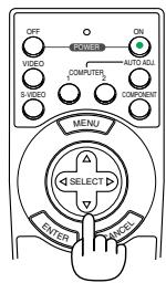
During Computer mode
In Computer mode, by pressing the ENTER button for 2 seconds or more then releasing, the drag mode is set and the drag operation can be performed simply by pressing the SELECT (mouse) button. To drop the item, press the ENTER (left click) button again or press the CANCEL (right click) button.
② Turning Off the Image and Sound
Press the PIC-MUTE button to turn off the image and sound for a short period of time. Press again to restore the image and sound.
NOTE: When a picture is muted, the Eco mode will be automatically selected in "Lamp Mode."
Freezing a Picture
Press the FREEZE button to freeze a picture. Press again to resume motion.
NOTE: Pressing the FREEZE button will display the Capture menu that allows you to capture a freezed image. See page 48 for more information.
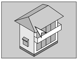
Using the Pointer
You can use one of nine pointers to draw your audience's attention to the portion of a projected image you want.
NOTE: You can select one pointer from the menu. See page 100.
Press the POINTER button to display the pointer.
Use the SELECT button to move the pointer. Press the POINTER buton again. The pointer will disappear.
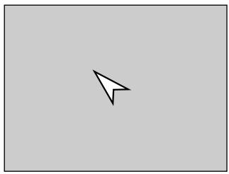

Press the Pointer button to display the pointer.
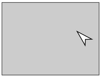
Use the Select button to move the pointer.
Enlarging and Moving a Picture
You can enlarge the area you want up to 400 percent.
To do so:
- Press the POINTER button to display the pointer.
- Move the pointer to the area you want to enlarge.
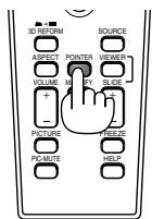
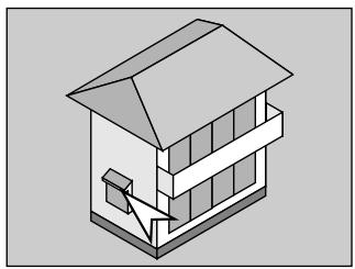
- Enlarge the selected area.
When the MAGNIFY (+) button is pressed, the image is magnified and the magnify icon will be displayed. To magnify the selected area, use the SELECT button to move the magnify icon and press the MAGNIFY (+) button.
- Return the image to the original size.
Press the MAGNIFY (-) button until the magnify icon changes to the pointer.
Getting the On-line Help
You get the contents about Help.
Display Help
Exit Help
Using a USB Mouse
Using a USB mouse gives you a smooth operation. A commercially available USB mouse can be used.
NOTE: There may be some brands of a USB mouse that the projector does not support.
Operate the Menu using the USB mouse
Mouse Cursor
When connecting a USB mouse to the projector, you get a mouse cursor on the screen.
Unless you use your USB mouse within 10 seconds, the mouse cursor disappears.
Menu Display
Clicking with the right mouse button displays the menu.
To close the menu, click anywhere in the background.
Source List Display
Click with the left button anywhere on the screen except on the menu to display the Source list.
Adjusting and Setting Display
You can select a menu item and click with the left mouse button to make adjustments and settings.
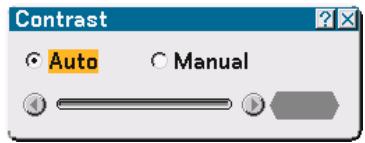
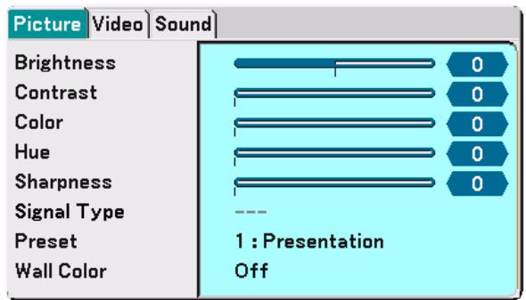
Examples
Click (or press and hold) the left mouse button or to adjust the brightness. Or click and drag the left mouse button on the slide bar horizontally to adjust it.
To save the adjustments, click X. The display is closed.
- Click with the left mouse button to display a description of the selected menu item.
- Click and drag the title bar with the left mouse button to move the adjustment or setting dialog box.
- Use the right mouse button (right-click) on the adjustment or setting dialog box to return to the previous screen with storing changes.
Using the Remote Mouse Function
The built-in remote mouse function enables you to operate your computer's mouse functions from the remote control (Computer mode).
It is very convenient for clicking through your computer-generated presentations. To return to the projector operation mode (Projector mode), press the PJ button (lit red).
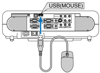
Connecting to your computer for the remote mouse function
If you wish to use the remote mouse function, use the supplied USB cable to connect the USB port (COMPUTER) of the projector and the USB port (type A) of your computer.
NOTE: Depending on the type of connection or OS installed on your computer, you may have to restart your computer or change your computer settings.
When using the USB Port
The remote mouse function can only be used with a Windows 98, Windows Me, Windows XP, Windows 2000 or Mac OS operating system.
NOTE: Wait at least 5 seconds after disconnecting the USB cable before reconnecting it and vice versa. The computer may not identify the built-in mouse receiver if it is repeatedly connected and disconnected in rapid intervals.
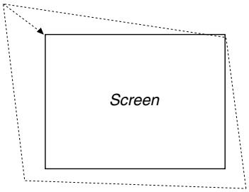
Correcting Horizontal and Vertical Keystone Distortion (Cornerstone)
Use the 3D Reform feature to correct keystone (trapezoidal) distortion to make the top or bottom and the left or right side of the screen longer or shorter so that the projected image is rectangular.
Cornerstone
- Press and hold the 3D REFORM button for a minimum of 2 seconds to reset current adjustments.
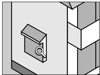
Current adjustments for "Keystone" or "Cornerstone" will be cleared. - Project an image so that the screen is smaller than the area of the raster.
- Pick up any one of the corners and align the corner of the image with a corner of the screen.
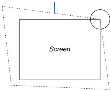
Projected image
The drawing shows the upper right corner.
- Press the 3D REFORM button on the remote control twice.
The Cornerstone adjustment screen is displayed.
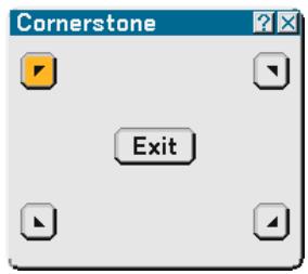
- Use the SELECT button to select one icon which points in the direction you wish to move the projected image frame.
- Press the ENTER button.
- Use the SELECT button to move the projected image frame as shown on the example.
8. Press the ENTER button.
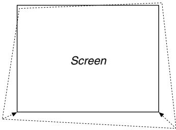
9. Use the SELECT button to select another icon which points in the direction.
On the Cornerstone adjustment screen, select "Exit" or press the CANCEL button on the remote control.
The confirmation screen is displayed.
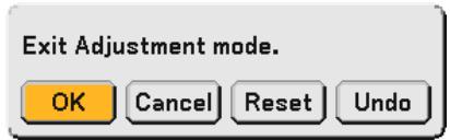
10. Press the SELECT or button to highlight the [OK] and press the ENTER button.
This completes the keystone correction.
Selecting "Cancel" will return to the adjustment screen without saving changes (Step 3).
Selecting "Reset" will return to the factory default.
Selecting "Undo" will exit without saving changes.
NOTE: To return the 3D Reform correction setting values to the factory default, press and hold the 3D REFORM button for a minimum of 2 seconds.
NOTE: During 3D Reform adjustment, "Aspect Ratio" and "Screen" may not be available. Should this happen, first reset the 3D Reform data and then do each setting. Second repeat the 3D Reform adjustment. Changing Aspect Ratio and/or Screen setting can limit 3D Reform in its adjustable range.
The adjustable ranges for 3D Reform are as follows:
| Horizontal | Vertical | |
| Cornerstone | Max. +/- 35° approx. | Max. +/- 40° approx. |
| Keystone | Max. +/- 27° approx. |
-
The following are conditions under which the maximum angle is achieved:
-
Image (100") is projected in Wide (Zoom lever)
- Resolution is XGA
Higher resolution than XGA narrows the adjustable range.
- Menu items should be set as follows:
Aspect Ratio 4:3
Screen Type 4:3
Horizontal and Vertical are adjusted separately.
A combination of both adjustments narrows the adjustable range.
- When "4:3 Fill" is selected in Aspect Ratio, "Cornerstone" and "Horizontal Keystone" are not available.
NOTE:
- If the Cornerstone screen is unavailable (grayed), press and hold the 3D REFORM button for a minimum of 2 seconds to reset the current correction data. The Cornerstone function becomes available.
- Turning on the projector will reset the previous correction setting values if the projection angle is changed from the last use. If the projection angle is the same as in the last use, the previous correction setting values are retained in the memory. To use the previous correction setting values after changing projection angle, select "Manual" in "Keystone" from the menu. See page 87.
NOTE: The 3D Reform feature can cause an image to be slightly blurred because the correction is made electronically.
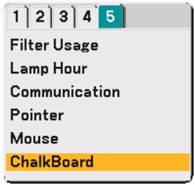
Making Freehand Drawings on a Projected Image (ChalkBoard)
The ChalkBoard feature allows you to write and draw messages on a projected image.
NOTE: The ChalkBoard feature is available only when a USB mouse is used.
To display the ChalkBoard tool bar, click the middle button on your mouse or select "ChalkBoard" from the menu. The tool bar contains the following icons.
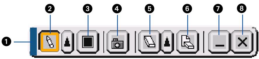
Drag ........ Drags to move the tool bar.
Pen Left-click and drag to draw. Left-click or right-click the pen icon to display the pen palette containing four lines of different thickness from which you can select a line you prefer by left-clicking.
Color .... Selects a color. Left-click to display the color palette from which you can select a color you prefer by leftclicking.
Capture. Left-click to capture a drawing on the ChalkBoard screen and save it to your PC-card inserted into the PC card slot of the projector.
Eraser Left-click and drag to erase part of a drawing. Left-click or right-click the eraser icon to display the eraser palette containing four eraser of different thickness from which you can select an eraser you prefer by left-clicking.
Clear ......... Left-click to clear the drawing completely from the ChalkBoard screen.
7 Hide............ Hides the tool bar by left-clicking. Right-clicking anywhere on the screen displays the ChalkBoard tool bar again.
Exit .... Creaks the complete drawing and exits the ChalkBoard.
NOTE:
- The menu is not available while you display the ChalkBoard screen.
- Selecting another source or switching slides in the Viewer clears a drawing completely.
Storage Images Displayed on the Projector on the PC card or USB memory (Capture)
The Capture features allows you to capture an image from a source that is currently being displayed. The image is saved as JPEG in the PC card or USB memory.
NOTE:
- Unless a PC card or USB memory is inserted into the PC Card slot or USB (MOUSE) port of the projector, the Capture feature is not available.
- The "Card Error" display means that the free space of the PC card or USB memory is insufficient for saving images. Make more space available on the card by erasing unwanted images with your PC. The number of images that can be captured depends on the size of the PC card.
- Be sure not to turn off the power or remove the PC card or USB memory while capturing an image. Doing so could cause a loss of the data in the PC card or USB memory or damage to the card itself.
Preparations:
Insert the PC card into the PC card slot or USB (MOUSE) port of the projector.
Insert the PC card so that the end with the insertion direction arrow on the top goes in first.
-
Press the eject button to eject the card.
-
Project the image you wish to store on the projector.
- Press the FREEZE button on the remote control.
- Press the MENU button to display the Capture menu.
Capture....... Captures an image and save it as a JPEG file in a PC card or USB memory.
Drive......... Select the PC Card or USB memory. You can capture an image and save it to your PC card or USB memory.
Exit ........ Exits the Capture function. Another option to exit the Capture function is to press MENU or CANCEL button on the remote control or projector cabinet.
NOTE:
Captured images with higher resolution than the projector's native resolution cannot be displayed correctly.
- File size of the captured image varies depending on the resolution of an input signal.
- An hourglass indicating that an image is being captured appears on the projector's display. Do not eject the PC card or turn off the projector's power while this icon is displayed. Doing so will damage the PC card data. If the PC card data is damaged, use a computer to repair the data.
Preventing the Unauthorized Use of the Projector
Assigning a keyword prevents the projector from being used by unauthorized individuals.
Assigning a Keyword for the first time
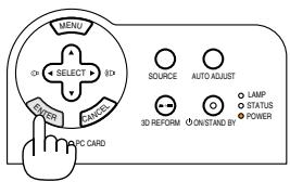
- Press the MENU button.
The menu will be displayed.

- Press the SELECT button twice to highlight the Setup menu and press the ENTER button. The page tab "1" will be highlighted.
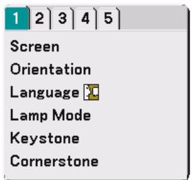

- Press the SELECT button once to highlight the page tab "2".
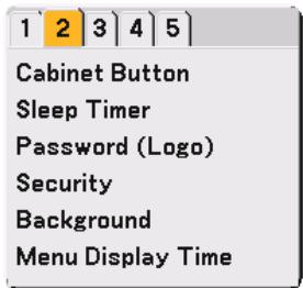

- Press the SELECT button four times to highlight "Security".
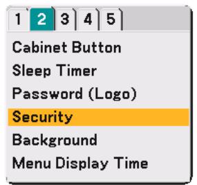

- Press the ENTER button to display the Security screen.
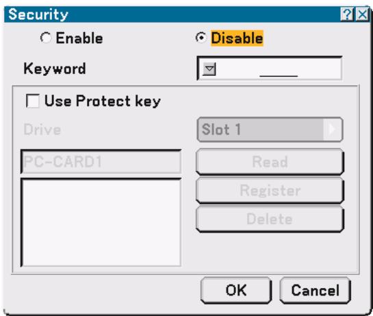
- Press the ENTER button once to highlight the Keyword entry box and press the ENTER button.
The Software keyboard will be displayed.
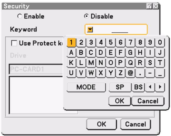
- Enter an alphanumeric keyword using the Software keyboard For example, to enter "1234", follow the steps 7-1 to 7-4 below.
NOTE:
- Please make a note of your keyword.
- Do not use spaces (SP) in your keyword.
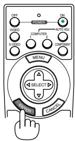
7-1. Highlight the number "1" and press the ENTER button.
The number "1" will be displayed in the Keyword entry box.
7-2. Press the SELECT button once to highlight "2" and press the ENTER button.
The number "12" will be displayed in the Keyword entry box.
7-3. For "3" and "4", use the same procedure as step 7-2.
The number "1234" will be displayed in the Keyword entry box.
7-4. Press the SELECT button to highlight "OK" and press the ENTER button.
The Software keyboard will disappear.
- Press the SELECT button once to highlight "Disable" and press the SELECT button to highlight "Enable".
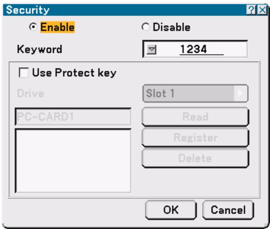
- Press the SELECT button to highlight "OK" and press the ENTER button. The confirmation screen will be displayed.
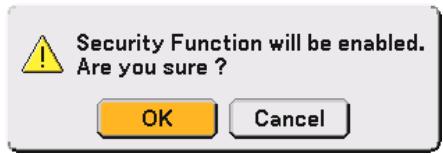
- Press the ENTER button. The Security Function is now enabled.
NOTE: A PC card can be used as a protect key. You can skip the keyword entry by inserting a registered PC card when turning on the projector. See page 91.
Checking If Security is enabled
Turn off the projector and turn it back on to check if the Security function is enabled.
- Press and hold the POWER (ON/STANDBY) button for a minimum of two seconds.
The lamp lights off and the POWER indicator flashes orange. Please wait until the POWER indicator changes from flashing to steady light. - When the POWER indicator lights steady orange, push the Main POWER switch to the off position (O).
The projector will turn off. - Push the Main POWER switch to the on position (I).
The POWER indicator lights orange. The projector is in standby condition. - Press and hold the POWER (ON/STANDBY) button for a minimum of two seconds.
The projector will turn on. The "Projector is locked! Enter your keyword." message will be displayed at the bottom of the screen. - Press the MENU button.
The on-screen menu will be displayed. - Press the SELECT button to highlight "Setup" and press the ENTER button.
The page tab "1" will be highlighted. - Press the SELECT button once to highlight the page tab "2".
- Press the SELECT button four times to highlight "Security" and press the ENTER button.
The Keyword entry screen will be displayed
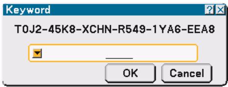
- Press the ENTER button.
The Software keyboard will be displayed.
- Use the same procedures as steps 1 to 7 described in the "Assigning a Keyword for the first time" section to enter "1234".
Each time one number is entered, an “**” (asterisk) will appear. Keyword appears as asterisks so the real keyword is hidden.
- After entering your keyword, highlight "OK" and press the ENTER button.
The Software keyboard will disappear. This will allow you to operate the projector.
Disabling the Security
- Press the MENU button. The on-screen menu will be displayed.
- Press the SELECT button to highlight "Setup" and press the ENTER button. The page tab "1" will be highlighted.
- Press the SELECT button once to highlight the page tab "2".
- Press the SELECT button four times to highlight "Security" and press the ENTER button. The Keyword entry screen will be displayed
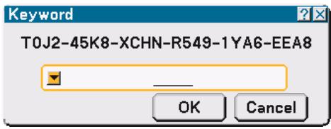
- Press the ENTER button. The Software keyboard will be displayed.
- Use the same procedures as steps 1 to 7 described in the "Assigning a Keyword for the first time" section to enter "1234".
Each time one number is entered, an “**” (asterisk) will appear. Keyword appears as asterisks so the real keyword is hidden.
- After entering your keyword, highlight "OK" and press the ENTER button. The Software keyboard will disappear. The Security screen will be displayed.
- Highlight "Enable" and press the SELECT button to highlight "Disable".
- Press the SELECT button to highlight "OK" and press the ENTER button. The Security Function is now disabled.
NOTE: To enable the Security again, enter your keyword again. Make sure that your keyword is correct.
Using a USB Memory Device or USB Memory Card Reader
The projector is compatible with either a USB memory device or USB memory card reader which supports the viewer and security features.
- To use a USB memory device or USB memory card reader, connect the device to the USB (MOUSE) port (type A).
- Select one of the drive icons for your USB memory in a pane on the left side of the Viewer window.
- To use a USB memory device as a Protect key for Security function, select one from the Drive icons in the Security setting screen. See page 91.
NOTE:
- Some USB memory devices (brands) or USB memory card readers may not work.
- The projector does not support FAT32 or NTFS formatted flash memory card or USB memory device.
Be sure to use a flash memory card or USB memory device formatted with the FAT16 or FAT file system.
To format your flash memory card or USB memory device in your computer, refer to the document or help file that comes with your Windows.
- You cannot use a USB memory device and a USB memory card reader when connecting a USB mouse to the projector.
-
Do not do the following while the USB memory device or USB memory card reader's access indicator is lit or flashing (while data is being accessed.) Doing so can damage your USB memory device or USB memory card in the reader. Back up your data in case it will need to be restored.
-
Pulling out the USB memory device or USB memory card reader from the USB port of the projector.
- Pulling out the memory card from the USB memory card reader
-
Turning off the main power switch or unplugging the power cable.
-
The drive for "USB 1-4" is displayed only when the USB memory device or USB memory card reader is connected to the projector. The drive for "USB 1-4" may be displayed differently from the one in the USB memory card reader.
- Some USB memory devices (brands) or USB memory cards cannot be used as Protect key for the projector's Security function.
5
Using the Viewer
Making the Most out of the Viewer Function 56
Operating the Viewer Function from the Projector..... 58
Changing Background Logo 64
Making the Most out of the Viewer Function
Features
You can view presentation data, capture and play images on the projector. A PC card is used to view presentation data prepared on the computer and to capture and play images projected with the projector.
The Viewer feature allows you to view slides stored on a PC memory card (referred to as PC card in this manual) or USB memory on the projector. Even if no computer is available, presentations can be conducted simply with the projector. This feature is convenient for holding presentations at meetings and in offices, as well as for playing images taken on digital cameras.
NOTE:
- To use the Viewer, first you need to create presentation materials on your PC (JPEG, BMP, Index* files).
For creating presentation materials using the Dynamic Image Utility 2.0.
* "Index" file is a file created using the Dynamic Image Utility 2.0 contained on the supplied NEC Projector User Supportware CD-ROM.
See "Using Dynamic Image Utility 2.0 on the supplied CD-ROM" for installing the Dynamic Image Utility 2.0 on your computer.
Easy to use
- Presentations can be started immediately simply by inserting a PC card or USB memory (not supplied)
- Easy slide switching
Remote control operation - Jumping to a list of slides or any specific slide
High quality images
High resolution up to 1024 x 768 dots
24-bit full color playback
Viewing of digital camera images
Simple utility software (for computer)
- Dynamic Image Utility 2.0 operable on Windows 98/Windows Me/Windows XP/Windows 2000
- Slides can be created by capturing the currently displayed image
Control screen for displaying lists of slides and editing - Microsoft, Windows and PowerPoint are registered trademarks of Microsoft Corporation.
Inserting and Removing a PC Card
NOTE:
- Do not try to force the PC card into the slot.
- A dummy card is inserted into the PC CARD slot at the time of shipment. First remove the dummy card before use.
Inserting the PC Card
- Hold the PC card horizontally and insert it slowly into the PC card slot with its top facing up.
Removing the PC Card
NOTE: Do not eject the PC card while its data is being accessed.
Press the eject button twice. The PC card pops out a little. Grasp the edges of the PC card and pull it out.
Direction for Inserting the PC Card
The PC card has a top and bottom and must be inserted into the PC card slot in a specific direction. It cannot be inserted backwards or upside-down. Attempting to force it into the slot in the wrong direction may break the internal pin and damage the card slot. Refer to the PC card's operating instructions for the proper direction of insertion.
PC Card Type
The PC Card slot accepts PCMCIA Type II only.
NOTE: The projector does not support FAT32 or NTFS formatted flash memory card or USB memory device.
Be sure to use a flash memory card or USB memory device formatted with the FAT16 or FAT file system.
To format your flash memory card or USB memory device in your computer, refer to the document or help file that comes with your Windows.
Operating the Viewer Function from the Projector (playback)
This section describes the operation for showing slides created using the Viewer function with the projector. It is also possible to make slides directly from the images projected with the projector.
Projecting slides (Viewer)
Preparation: Use the Capture feature to store JPEG or BMP files in a PC card or USB memory inserted into the projector's slot. Or store JPEG or BMP files in a PC card or USB memory inserted into your PC.
- Insert a PC card into the PC card slot of the projector.
- Press the VIEWER button on the remote control or select the "Viewer" from the source list.
An image stored in the PC card will be displayed.
- Press the MENU button to display the Viewer menu.
The Viewer menu will appear when you press the MENU button on the remote control or the projector cabinet.
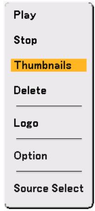
The Viewer menu includes the following commands:
Play ....... Plays back automatically or manually depending on the setting in Option. This allows you to move on to the next slide when "Manual Play" is selected in the "Play Mode".
Stop ........ This allows you to stop Auto Play while you are playing back and to resume playing from the selected slide or folder when "Auto Play" is selected in the "Play Mode".
Thumbs... Displays a list of thumbnails of JPEG or BMP files stored in the PC card inserted into the projector.
Delete ........ deletes a captured slide(s) or all the captured slides in the Capture - specific folder.
Logo Replace the default background logo with another logo in JPEG or BMP format.
Option......... Displays the Viewer setting options.
Source Select .... Displays the Source list.
- Select "Play" and then press the ENTER button to display the first slide or to start playing slides automatically.
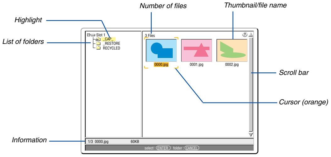
Viewer Window Elements
Highlight Indicates the selected folder or drive.
List of folders Indicates folders contained on a PC card or USB memory.
Information.. Indicates information of the selected file or folder
Folder: folder name, creation date, creation time
File: slide number/number of displayable slides in a folder, file name, creation date, creation time, file size
Number of files ........ Indicates number of displayable slides in the selected folder. The maximum number of images recognized as slides within one directory is 128.
Thumbnail/file name Indicates thumbnails and names contained in a folder.
Cursor Indicates the selected slide.
Scroll bar. Uses to view folders or files not visible in the window.
Setting Option for Viewer
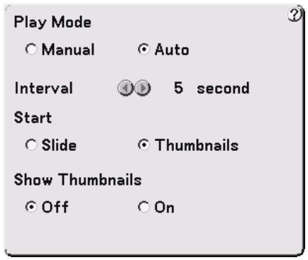
Play Mode:
Manual . Views a slide manually when the Viewer source is selected.
Auto Plays back slides automatically when the Viewer source is selected.
Interval:
Specifies interval time between 5 and 300 seconds.
Start:
Specifies start screen when the Viewer source is selected.
Show Thumbs:
Selecting the Viewer source will display a list of thumbnails of JPEG or BMP files stored in the PC card or USB memory when "On" is selected.
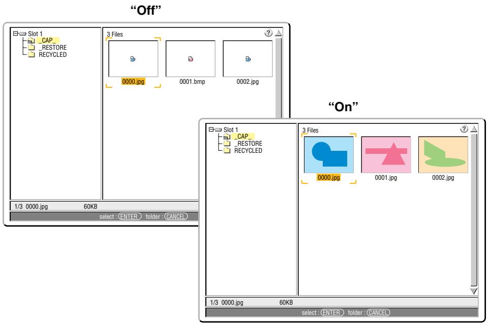
NOTE: If no memory card is inserted in the PC CARD slot, there is no signal, and a black, blue or logo background is displayed, depending on the setting. Playback is stopped when button on the cabinet or remote control is pressed in Auto Play mode.
Switching to Slides Directly from Other Input Modes
With this function it is possible to switch directly to a slide when the picture of a VCR or computer is being projected. Example: When conducting presentations using a combination of slides and moving pictures from a VCR, etc., it is possible to switch from a Viewer slide to the video picture then back to the Viewer slide simply by using the Viewer button.
NOTE: Even if you switch the current Viewer source to another source, the current slide is retained. When you return back to the Viewer, you will get the slide that has been retained.
Viewing Digital Images
Digital images can be played with the Viewer if the following conditions are met:
If the image can be stored on an MS-DOS format PC card.
- If the image can be stored in a format supported by the Viewer. With the Viewer, images on the card are searched for in directories and images in JPEG or BMP format are recognized as slides. Searchable directories are directories within two steps from the root directory, and searchable images are images within the first 12 files in the directory. Only file and slide switching are possible.
NOTE: The maximum number of images recognized as slides within one directory is 128.
Deleting Captured Images
Using the Delete command on the Viewer menu allows you to delete captured images.
To delete captured images:
Preparation: Make sure that the PC card is inserted into the PC card slot of the projector.
- Press the VIEWER button on the remote control to display an image.
- Press the MENU button to display the Viewer menu.
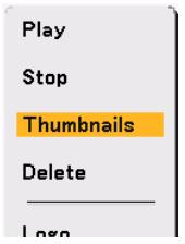
- Use the button to select "Thumbs nails" and then press the ENTER button. The Thumbnail screen will be displayed.
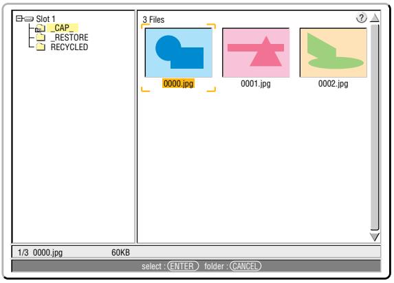
NOTE: To change highlight from the Thumbsills screen (pane on the right) to a directory tree (pane on the left), press the CANCEL button. To return highlight to the Thumbsills screen, press the ENTER button.
- Use the buttons to select an image you wish to delete.
- Press the MENU button to display the Viewer menu.
- Use the button to select "Delete" and then press the ENTER button.
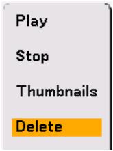
A confirmation message will be displayed.
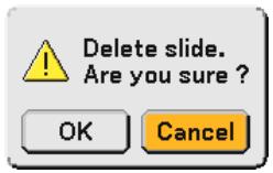
- Use the button to select "OK" and then press the ENTER button.
This completes deleting.
To delete all the captured images:
- Repeat steps 1 to 3 in the above described procedure.
- Press the CANCEL button to select the "CAP" folder in the directory (pane on the left).
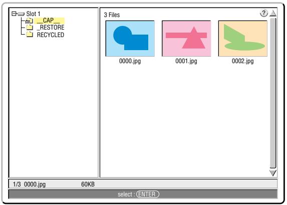
- Press the MENU button to display the Viewer menu.
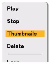
- Use the button to select "Delete" and then press the ENTER button.
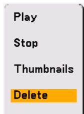
A confirmation message will be displayed.
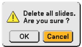
- Use the button to select "OK" and then press the ENTER button.
This completes deleting.
NOTE: The vacant "CAP" folder stays even after you delete all the captured images.