MT850 - Projector NEC - Free user manual and instructions
Find the device manual for free MT850 NEC in PDF.
User questions about MT850 NEC
0 question about this device. Answer the ones you know or ask your own.
Ask a new question about this device
Download the instructions for your Projector in PDF format for free! Find your manual MT850 - NEC and take your electronic device back in hand. On this page are published all the documents necessary for the use of your device. MT850 by NEC.
USER MANUAL MT850 NEC
natural_image
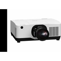
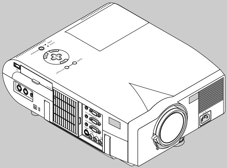
Exterior view of a projector labeled MT1050 (no additional text or symbols visible)LIMITED WARRANTY (USA and Canada only)
NEC SOLUTIONS' PROJECTOR PRODUCTS
NEC Solutions (America), Inc. (hereafter NEC Solutions) warrants this product to be free from defects in material and workmanship under the following terms.
HOW LONG IS THE WARRANTY
NEC Solutions' MT1055, MT1050 and MT850 projectors are covered by a two (2) year limited parts and labor warranty from the date of the first customer purchase. The lamp when used under normal operating conditions is warranted for 1000 hours or six months, whichever comes first.
WHO IS PROTECTED
This warranty may be enforced only by the first purchaser, and is not transferable.
WHAT IS COVERED AND WHAT IS NOT COVERED
Except as specified below, this warranty covers all defects in material or workmanship in this product.
NEC SOLUTIONS' LIABILITY FOR ANY DEFECTIVE PRODUCT IS LIMITED TO THE REPAIR OR REPLACEMENT OF THE PRODUCT AT NEC SOLUTIONS' OPTION. REPLACEMENT PRODUCTS MAY BE NEW OR 'LIKE NEW'. The following are not covered by the limited warranty and NEC Solutions shall not be liable for:
- Any product which is not distributed in the U.S.A. or Canada by NEC Solutions or which is not purchased, installed, and operated in the U.S.A or Canada.
- Any product on which the serial number has been defaced, modified or removed.
- Normal decrease in lamp light output over time.
- Damage, deterioration or malfunction resulting from:
a. Accident, misuse, abuse, neglect, improper ventilation, fire, dust, smoke, water, lightning or other acts of nature, unauthorized product modification, or failure to follow instructions supplied with the product.
b. Repair or attempted repair by anyone other than a NEC Solutions authorized service center.
c. Any shipment of the product (claims must be presented to the carrier).
d. Removal or installation of the product.
e. Any other cause which does not relate to a product defect.
f. Use of the product beyond normal operating conditions. Normal operating conditions are defined as product use not in excess of 5 hours per day and 260 days per year.
-
Cartons, carrying cases, shipping cases, batteries, external cabinets, magnetic tapes, or any accessories used in connection with the product.
-
Service required as a result of third party components.
WHAT NEC SOLUTIONS WILL PAY FOR
NEC Solutions will pay labor and material expenses for covered items, but NEC Solutions will not pay for the following:
- Removal or installation charges.
- Costs of technical adjustments, set-up, maintenance, or adjustment of user controls.
- Payment of shipping and related charges incurred in returning the product for warranty repair.
HOW YOU CAN GET WARRANTY SERVICE
- To obtain service on your product, consult the dealer from whom you purchased the product.
- Whenever warranty service is required, the original dated invoice (or a copy) must be presented as proof of warranty coverage. In order to obtain warranty service, you may be required to describe and demonstrate the problem to your dealer or to NEC Solutions.
- All products returned to NEC Solutions for service MUST have prior approval. To receive approval or for the name of the nearest NEC Solutions authorized service center, call NEC Solutions at 800-836-0655.
- It shall be your obligation and expense to ship the product, freight prepaid, or to deliver it to a NEC Solutions authorized service center, in either the original package or a similar package affording an equal degree of protection.
- In the event a product is returned to NEC Solutions for warranty service, and it is determined that there is no product defect or that the product condition is not covered by this limited warranty, a diagnostic service fee may be charged to the customer.
LIMITATION OF IMPLIED WARRANTIES
EXCEPT AS EXPRESSLY SET FORTH IN THIS LIMITED WARRANTY, NEC SOLUTIONS MAKES NO OTHER WARRANTIES, EXPRESS OR IMPLIED, INCLUDING BUT NOT LIMITED TO ANY IMPLIED WARRANTIES OR CONDITIONS OF MERCHANTABILITY AND FITNESS FOR A PARTICULAR PURPOSE. ANY IMPLIED WARRANTIES THAT MAY BE IMPOSED BY LAW ARE LIMITED TO THE TERMS AND DURATION OF THIS LIMITED WARRANTY.
EXCLUSION OF DAMAGES
NEC SOLUTIONS' LIABILITY FOR ANY DEFECTIVE PRODUCT IS LIMITED TO THE REPAIR OR REPLACEMENT OF THE PRODUCT AT NEC SOLUTIONS' OPTION. NEC SOLUTIONS SHALL NOT BE LIABLE FOR:
- DAMAGE TO OTHER PROPERTY CAUSED BY ANY DEFECTS IN THIS PRODUCT, DAMAGES BASED UPON INCONVENIENCE, LOSS OF USE OF THE PRODUCT, LOSS OF TIME, COMMERCIAL LOSS; OR
- ANY OTHER DAMAGES, WHETHER INCIDENTAL, CONSEQUENTIAL OR OTHERWISE.
HOW STATE LAW RELATES TO THE WARRANTY
SOME STATES DO NOT ALLOW LIMITATIONS ON HOW LONG AN IMPLIED WARRANTY LASTS AND/OR DO NOT ALLOW THE EXCLUSION OR LIMITATION OF INCIDENTAL OR CONSEQUENTIAL DAMAGES, SO THE ABOVE LIMITATIONS AND EXCLUSIONS MAY NOT APPLY TO YOU. THIS LIMITED WARRANTY GIVES YOU SPECIFIC LEGAL RIGHTS, AND YOU MAY HAVE OTHER RIGHTS WHICH VARY FROM STATE TO STATE.
FOR MORE INFORMATION, CONTACT:
NEC SOLUTIONS (AMERICA), INC.
1250 N. Arlington Heights Road, Suite 500
Itasca, Illinois 60143-1248
TELEPHONE 800-836-0655
www.necvisualsystems.com
Customers are cautioned that product performance is affected by system configuration, software, the application, customer data, and operator control, among other factors. While NEC Solutions' products are considered to be compatible with many systems, the specific functional implementation by the customers of the product may vary. Therefore, the suitability of a product for a specific purpose or application must be determined by the customer and is not warranted by NEC Solutions.
DECLARATION OF CONFORMITY
This device complies with Part 15 of FCC Rules. Operation is subject to the following two conditions. (1) This device may not cause harmful interference, and (2) this device must accept any interference received, including interference that may cause undesired operation.
U.S. Responsible Party: NEC Technologies, Inc.
Address: 1250 N. Arlington Heights Road Itasca, Illinois 60143
Tel. No.: (630) 467-5000
Type of Product: LCD Projector
Equipment Classification: Class B Peripheral
Models: MT1055, MT1050 and MT850

We hereby declare that the equipment specified above conforms to the technical standards as specified in the FCC Rules.
MultiSync MT1055/MT1050/MT850
LCD Projector
User's Manual
English
natural_image
Line drawing of a projector with labeled ports and control panel (no text or symbols beyond basic labels)IMPORTANT INFORMATION
Precautions
Please read this manual carefully before using your NEC MultiSync MT1055/MT1050/MT850 Projector and keep the manual handy for future reference.
Your serial number is located under the name plate label on the left side of your MultiSync MT1055/MT1050/MT850. Record it here:
CAUTION

To turn off main power, be sure to remove the plug from power outlet.
The power outlet socket should be installed as near to the equipment as possible, and should be easily accessible.
CAUTION

TO PREVENT SHOCK, DO NOT OPEN THE CABINET. NO USER-SERVICEABLE PARTS INSIDE.
REFER SERVICING TO QUALIFIED NEC SERVICE PERSONNEL.

This symbol warns the user that uninsulated voltage within the unit may be sufficient to cause electrical shock. Therefore, it is dangerous to make any kind of contact with any part inside of the unit.

This symbol alerts the user that important information concerning the operation and maintenance of this unit has been provided. The information should be read carefully to avoid problems.
WARNING
TO PREVENT FIRE OR SHOCK, DO NOT EXPOSE THIS UNIT TO RAIN OR MOISTURE.
DO NOT USE THIS UNIT'S GROUNDED PLUG WITH AN EXTENSION CORD OR IN AN OUTLET UNLESS ALL THREE PRONGS CAN BE FULLY INSERTED.
DO NOT OPEN THE CABINET. THERE ARE HIGH-VOLTAGE COMPONENTS INSIDE. ALL SERVICING MUST BE DONE BY QUALIFIED NEC SERVICE PERSONNEL.
DOC Compliance Notice
This Class B digital apparatus meets all requirements of the Canadian Interference-Causing Equipment Regulations.
3. GSGV Acoustic Noise Information Ordinance:
The sound pressure level is less than 70 dB (A) according to ISO 3744 or ISO 7779.
| CAUTIONLASER RADIATION-DO NOT STATE INTO BEAMWAVE LENGTH: 650nmMAX. OUTPUT: 1mWCLASS 2 LASER PRODUCTレーザー光 ビームをのぞき込まないこと最大出力:1mW レーザーダイオード:650nm | RADIACION LASERNO MIRE AL RAYOPRODUCTO LASER CLASSE2 | REMOTECONTROLMODEL:RD-367E7N900011 |
| LASER-STRAHLUNGNICHT IN DEN STRAHLBLICKEN ! LASER KLASSE2 | ||
| RAYONNEMENT LASER NE PASREGARDER DANS LE FAISCEAUAPPAREIL A LASER DE CLASSE2 | ||
| EN60825-1 : 1994 + A11 : 1996 MADE IN CHINA | ||
This label is located on the back of the remote control.
RF Interference
WARNING
The Federal Communications Commission does not allow any modifications or changes to the unit EXCEPT those specified by NEC Technologies in this manual. Failure to comply with this government regulation could void your right to operate this equipment.
This equipment has been tested and found to comply with the limits for a Class B digital device, pursuant to Part 15 of the FCC Rules. These limits are designed to provide reasonable protection against harmful interference in a residential installation. This equipment generates, uses, and can radiate radio frequency energy and, if not installed and used in accordance with the instructions, may cause harmful interference to radio communications. However, there is no guarantee that interference will not occur in a particular installation. If this equipment does cause harmful interference to radio or television reception, which can be determined by turning the equipment off and on, the user is encouraged to try to correct the interference by one or more of the following measures:
- Reorient or relocate the receiving antenna.
- Increase the separation between the equipment and receiver.
- Connect the equipment into an outlet on a circuit different from that to which the receiver is connected.
- Consult the dealer or an experienced radio / TV technician for help.
In UK, a BS approved power cable with moulded plug has a Black (five Amps) fuse installed for use with this equipment. If a power cable is not supplied with this equipment please contact your supplier.
- IBM is a registered trademark of International Business Machines Corporation.
• Macintosh and PowerBook are registered trademarks of Apple Computer, Inc. - Other product and company names mentioned in this user's manual may be the trademarks of their respective holders.
Important Safeguards
These safety instructions are to ensure the long life of your projector and to prevent fire and shock. Please read them carefully and heed all warnings.
Installation
- For best results, use your projector in a darkened room.
- Place the projector on a flat, level surface in a dry area away from dust and moisture.
- Do not place your projector in direct sunlight, near heaters or heat radiating appliances.
- Exposure to direct sunlight, smoke or steam can harm internal components.
- Handle your projector carefully. Dropping or jarring can damage internal components.
- Do not place heavy objects on top of the projector.
- If you wish to have the projector installed on the ceiling:
a. Do not attempt to install the projector yourself.
b. The projector must be installed by qualified technicians in order to ensure proper operation and reduce the risk of bodily injury.
c. In addition, the ceiling must be strong enough to support the projector and the installation must be in accordance with any local building codes.
d. Please consult your dealer for more information.
Power Supply
- The projector is designed to operate on a power supply of 100-120 or 200-240 V 50/60 Hz AC. Ensure that your power supply fits this requirement before attempting to use your projector.
- Handle the power cable carefully and avoid excessive bending. A damaged cord can cause electric shock or fire.
- If the projector is not to be used for an extended period of time, disconnect the plug from the power outlet.
Cleaning
- Unplug the projector before cleaning.
- Clean the cabinet periodically with a damp cloth. If heavily soiled, use a mild detergent. Never use strong detergents or solvents such as alcohol or thinner.
- Use a blower or lens paper to clean the lens, and be careful not to scratch or mar the lens.
CAUTION
Do not unplug the power cable from the wall outlet under any one of the following circumstances. Doing so can cause damage to the projector:
- While the Hour Glass icon appears.
- While the message "Please wait a little." appears. This message will be displayed after the projector is turned off.
- Immediately after the power cable is plugged into the wall outlet (the POWER indicator has not changed to a steady amber glow).
- Immediately after the cooling fan stops working (The cooling fan continues to work for ONE minute after the projector is turned off with the POWER button).
- While the POWER and the STATUS indicators are alternately flashing.
CAUTION
Do not put the projector on its side when the lamp is turned on. Doing so may cause damage to the projector.
Lamp Replacement
- To replace the lamp, follow all instructions provided on page E-47.
- Be sure to replace the lamp when the message "The Lamp has reached the end of its usable life. Please replace the lamp." appears. If you continue to use the lamp after the lamp has reached the end of its usable life, the lamp bulb may shatter, and pieces of glass may be scattered in the lamp case. Do not touch them as the pieces of glass may cause injury. If this happens, contact your NEC dealer for lamp replacement.
- Allow a minimum of ONE minute to elapse after turning off the projector. Then disconnect the power cable and allow 60 minutes to cool the projector before replacing the lamp.
Fire and Shock Precautions
- Ensure that there is sufficient ventilation and that vents are unobstructed to prevent the build-up of heat inside your projector. Allow at least 3 inches (10 cm) of space between your projector and a wall.
- Prevent foreign objects such as paper clips and bits of paper from falling into your projector. Do not attempt to retrieve any objects that might fall into your projector. Do not insert any metal objects such as a wire or screwdriver into your projector. If something should fall into your projector, disconnect it immediately and have the object removed by a qualified NEC service personnel.
- Do not place any liquids on top of your projector.
- Do not look into the lens while the projector is on. Serious damage to your eyes could result.
- Keep any items such as magnifying glass out of the light path of the projector. The light being projected from the lens is extensive, therefore any kind of abnormal objects that can redirect light coming out of the lens, can cause unpredictable outcome such as fire or injury to the eyes.
- Do not cover the lens with the supplied lens cap or equivalent while the projector is on. Doing so can lead to melting of the cap and possibly burning your hands due to the heat emitted from the light output.
- Do not look into the laser pointer while it is on and do not point the laser beam at another person. Serious injury could result.
TABLE OF CONTENTS
1. INTRODUCTION
Introduction to the MultiSync MT1055/MT1050/MT850 Projector ...... E-5
Getting Started.... E-5
What's in the Box ...... E-6
Getting to Know Your MultiSync MT1055/MT1050/MT850 Projector ..... E-7
Front / Side Features ...... E-7
Rear / Side Features.... E-7
Top Features ...... E-8
Terminal Panel Features ...... E-9
Remote Control Features E-10
Remote Control Battery Installation ...... E-12
Operating Range ...... E-12
Remote Control Precautions E-12
Switching Operation mode between mouse and projector ..... E-13
2. INSTALLATION
Setting Up Your Projector E-14
Selecting a Location E-14
Using a Tabletop or Cart E-14
Adjusting the Tilt Foot.... E-15
Distance Chart ...... E-16
Ceiling Installation E-16
Reflecting the Image ...... E-16
Wiring Diagram E-18
Connecting Your PC E-19
Connecting Your Macintosh Computer .... E-20
Connecting Your Computer to the Mouse Output Port ...... E-21
Connecting an External Monitor E-21
Connecting Your DVD Player E-22
Connecting Your VCR or Laser Disc Player ...... E-23
About Startup screen (Menu Language Select screen) ...... E-24
3. OPERATION
General Controls ...... E-25
Using the Menus E-25
Using a USB Mouse E-25
Basic Operation ...... E-26
Adjust the Image Using Auto Adjust E-26
Using Pointer E-27
Enlarging and Moving a Picture E-27
Correcting Keystone Distortion E-28
Freezing a Picture E-28
Customizing Basic/Custom Menu E-28
Menu Tree E-30
Menu Elements ...... E-31
Menu Descriptions & Functions ...... E-32
Source Select E-32
RGB1&2/Video/S-Video/PC Card Viewer
Picture E-32
Brightness/Contrast/Color/Hue/Sharpness
Volume E-32
Image Options ...... E-33
Keystone E-33
Color Temperature E-33
Lamp Mode E-33
Gamma Correction E-33
Aspect Ratio E-33
Noise Reduction E-34
Color Matrix E-34
White Balance E-34
Position/Clock E-34
Resolution E-34
Factory Default E-35
Projector Options ...... E-35
Menu E-35
Menu Mode ...... E-35
Advanced Menu, Basic/Custom Menu ...... E-35
Language E-35
Projector Pointer E-35
Source Display E-35
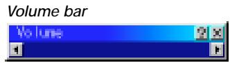
Direct Button (Volume Bar and Keystone Bar) ...... E-35
Menu Display Time E-35
Setup E-36
Orientation E-36
Background E-36
Mouse Settings E-36
Button/Sensitivity E-36
PC Card Viewer Options ...... E-36
Capture Options ...... E-36
Signal Select E-36
Auto Adjust (RGB only) E-37
Auto Start E-37
Power Management E-37
Power Off Confirmation E-37
Keystone Save E-37
Fan High Speed Mode E-37
Auto Mute for Built-in Speaker E-37
Clear Lamp Hour Meter E-37
Remote Sensor E-37
S-Video Mode Select E-37
RGBOUT Terminal E-37
Communication Speed E-38
Default Source Select E-38
Tools E-38
Capture E-38
PC Card Files ...... E-38
Changing Background Logo E-39
Chalk Board E-39
Help E-39
Contents E-39
Information E-39
Using the PC Card Viewer Function.... E-40
Features E-40
Inserting and Ejecting a PC Card ...... E-40
Installing the PC Card Viewer Software ...... E-41
Starting Up the PC Card Viewer Software on your PC (PC Card Viewer Utility 10) ...... E-41
Operating the PC Card Viewer Function from the Projector ( playback) ...... E-42
Capturing Images Displayed on the Projector ...... E-44
Viewing Digital Images E-44
Uninstalling the PC Card Viewer Software ...... E-45
Terminology E-46
4. MAINTENANCE
Replacing the Lamp E-47
Cleaning or Replacing the Filters E-48
5. TROUBLESHOOTING
Power / Status Light Messages ...... E-49
Common Problems & Solutions ...... E-49
6. SPECIFICATIONS
Optical/Electrical/Mechanical E-51
Cabinet Dimensions ...... E-52
D-Sub Pin Assignments E-54
Timing Chart E-55
PC Control Codes ...... E-56
Cable Connection.... E-56
1. INTRODUCTION
Introduction to the MultiSync MT1055/MT1050/MT850 Projector
This section introduces you to your new MultiSync MT1055 and MT1050 (XGA)/MT850 (SVGA) Projector and describes the features and controls.
Congratulations on Your Purchase of The MultiSync MT1055/MT1050/MT850 Projector
The MultiSync MT1055/MT1050/MT850 is one of the very best projectors available today. The MultiSync MT1055/MT1050/MT850 enables you to project precise images up to 300 inches across (measured diagonally) from your PC or Macintosh computer (desktop or notebook), VCR, DVD player, document camera, a laser disc player or PC Card Viewer.
You can use the projector on a tabletop or cart, you can use the projector to project images from behind the screen, and the projector can be permanently mounted on a ceiling ^*1 . The remote control can be used wirelessly.
Features you'll enjoy:
- Simple set up and operation.
- Hot air blown from the vents does not bother the audience during your presentation since the vents are located on the side.
• A high-performance 200 watt NSH lamp.
- The supplied wireless remote control that operates the projector from any angle.
- The image can be projected between 30 and 300 inches (measured diagonally).
- Keystone correction allows you to correct trapezoidal distortion so that the image is square.
- You can choose between video modes depending on your source: "normal" for a typical picture, "natural" for true color reproduction.
- The built-in PC Card Viewer allows you to start your presentation even when a PC is not available at the site.
- The "Capture" enables you to capture the current projected image.
- An image can be projected from in front or behind a screen, and the projector can even be installed on the ceiling.
- NEC Technologies' exclusive Advanced AccuBlend intelligent pixel blending technology - an extremely accurate image compression technology - offers a crisp image with UXGA (1600×1200) resolution ^*3 .
- Supports most IBM VGA, SVGA, XGA*2, SXGA/UXGA(with Advanced AccuBlend)*3, Macintosh, component signal (YCbCr/YPbPr) or any other RGB signals within a horizontal frequency range of 15 to 100kHz and a vertical frequency range of 50 to 120Hz . This includes NTSC, PAL, PAL60, SECAM and NTSC4.43 standard video signals.
NOTE: Composite video standards are as follows:
NTSC: U.S. TV standard for video in U.S. and Canada.
PAL: TV standard used in Western Europe.
PAL60: TV standard used for NTSC playback on PAL TVs.
SECAM: TV standard used in France and Eastern Europe.
NTSC4.43: TV standard used in Middle East countries.
- The supplied remote control can be used without a cable, and you can even use the remote control and mouse adapter to operate your PC or Macintosh mouse wirelessly from across the room with the built-in remote mouse receiver.
- You can control the projector with a PC using the PC Control port*4.
- USB terminal allows USB mouse operation *5.
- The contemporary cabinet design is light, compact, easy to carry, and complements any office, boardroom or auditorium.
- Eight pointers are available for your presentation.
*1 Do not attempt to mount the projector on a ceiling yourself. The projector must be installed by qualified technicians in order to ensure proper operation and reduce the risk of bodily injury. In addition, the ceiling must be strong enough to support the projector and the installation must be in accordance with any local building codes. Please consult your dealer for more information.
*2 An XGA image (1024×768) is converted into an 800×600 crisp image with NEC technology's Advanced AccuBlend on MT850.
*3 A UXGA (1600 × 1200) and SXGA image (1280 × 1024) is converted into a 1600 × 1200 and 1024 × 768 crisp image respectively with NEC technology's Advanced AccuBlend on MT1055/MT1050.
*4 The PC Control Utility 1.0 is required. This program is included on the supplied CD-ROM.
*5 The USB terminal meets the USB1.1 specification and accepts a USB mouse only.
Getting Started
The fastest way to get started is to take your time and do everything right the first time. Take a few minutes now to review the user's manual. This may save you time later on. At the beginning of each section of the manual you'll find an overview. If the section doesn't apply, you can skip it.
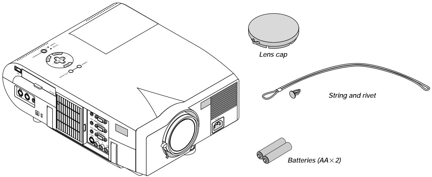
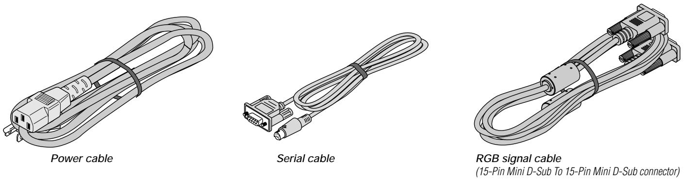
What's in the Box?
Make sure your box contains everything listed. If any pieces are missing, contact your dealer.
Please save the original box and packing materials if you ever need to ship your MultiSync MT1055/MT1050/MT850 Projector.
text_image
Lens cap String and rivet Batteries (AA × 2)NEC MultiSync MT1055, MT1050 or MT850 projector
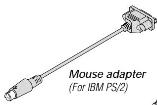
text_image
Mouse adapter (For IBM PS/2)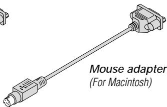
text_image
Mouse adapter (For Macintosh)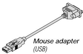
text_image
Mouse adapter (USB)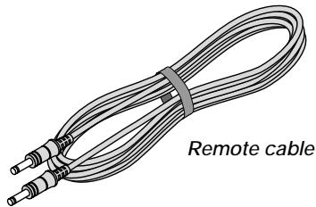
natural_image
Illustration of a flexible cable with two connectors and a labeled 'Remote cable' (no other text or symbols)
natural_image
Illustration of a CD-ROM drive with a square top and circular head (no text or symbols on the diagram itself)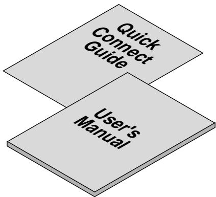
flowchart
graph TD
    A["Quick Connect Guide"] --> B["User's Manual"]
text_image
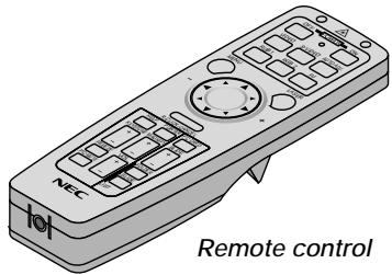
NEC Remote controlGetting to Know Your MultiSync MT1055/MT1050/MT850 Projector
Front/Side Features
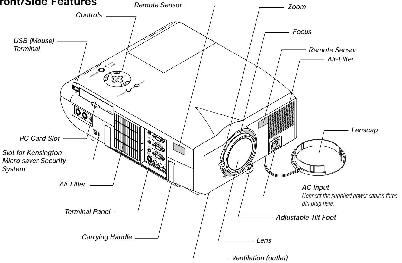
text_image
Front/Side Features Controls USB (Mouse) Terminal PC Card Slot Slot for Kensington Micro saver Security System Air Filter Terminal Panel Carrying Handle Remote Sensor Zoom Focus Remote Sensor Air-Filter Lenscap AC Input Connect the supplied power cable's three- pin plug here. Adjustable Tilt Foot Lens Ventilation (outlet)Rear/Side Features
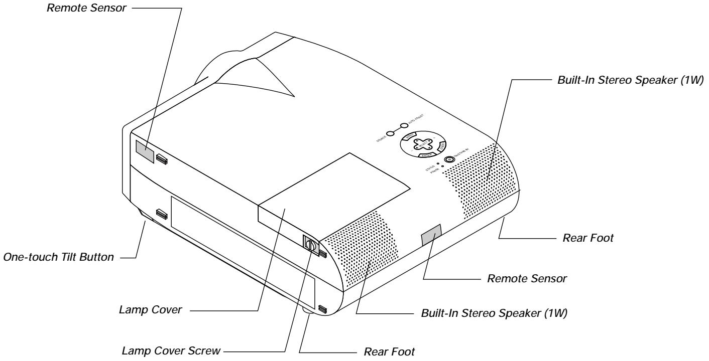
text_image
Remote Sensor Built-In Stereo Speaker (1W) One-touch Tilt Button Lamp Cover Lamp Cover Screw Rear Foot Remote Sensor Built-In Stereo Speaker (1W) Rear FootTop Features
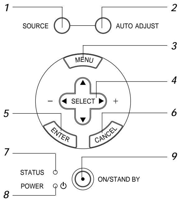
text_image
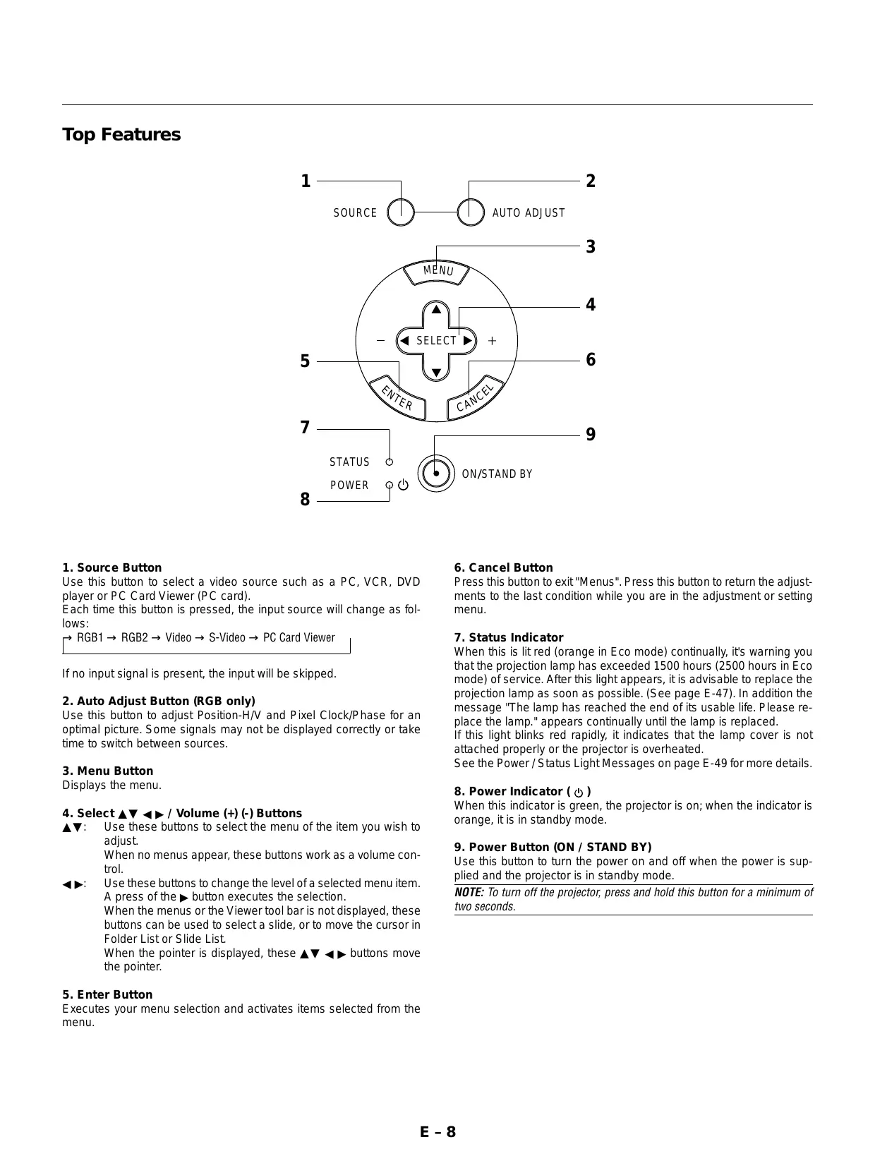
1 SOURCE AUTO ADJUST MENU - SELECT + ENTER CANCEL 5 6 7 STATUS POWER ON/STAND BY 81. Source Button
Use this button to select a video source such as a PC, VCR, DVD player or PC Card Viewer (PC card).
Each time this button is pressed, the input source will change as follows:

If no input signal is present, the input will be skipped.
2. Auto Adjust Button (RGB only)
Use this button to adjust Position-H/V and Pixel Clock/Phase for an optimal picture. Some signals may not be displayed correctly or take time to switch between sources.
3. Menu Button
Displays the menu.
4. Select ▲▼ ◀▶ / Volume (+) (-) Buttons
▲▼: Use these buttons to select the menu of the item you wish to adjust.
When no menus appear, these buttons work as a volume control.
◀▶: Use these buttons to change the level of a selected menu item. A press of the ▶ button executes the selection.
When the menus or the Viewer tool bar is not displayed, these buttons can be used to select a slide, or to move the cursor in Folder List or Slide List.
When the pointer is displayed, these ▲▼ ◀▶ buttons move the pointer.
5. Enter Button
Executes your menu selection and activates items selected from the menu.
6. Cancel Button
Press this button to exit "Menus". Press this button to return the adjustments to the last condition while you are in the adjustment or setting menu.
7. Status Indicator
When this is lit red (orange in Eco mode) continually, it's warning you that the projection lamp has exceeded 1500 hours (2500 hours in Eco mode) of service. After this light appears, it is advisable to replace the projection lamp as soon as possible. (See page E-47). In addition the message "The lamp has reached the end of its usable life. Please replace the lamp." appears continually until the lamp is replaced.
If this light blinks red rapidly, it indicates that the lamp cover is not attached properly or the projector is overheated.
See the Power / Status Light Messages on page E-49 for more details.
8. Power Indicator ( ⏻ )
When this indicator is green, the projector is on; when the indicator is orange, it is in standby mode.
9. Power Button (ON / STAND BY)
Use this button to turn the power on and off when the power is supplied and the projector is in standby mode.
NOTE: To turn off the projector, press and hold this button for a minimum of two seconds.
Terminal Panel Features
text_image
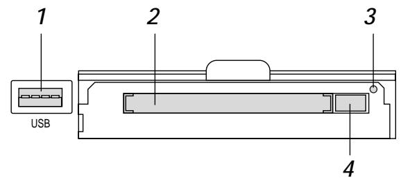
1 2 3 USB 4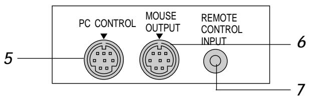
text_image
PC CONTROL MOUSE OUTPUT REMOTE CONTROL INPUT 5 6 71. USB Terminal
Connect a commercially available mouse that supports USB. You can operate the menu or PC Card Viewer with the USB mouse via this terminal.
Note that this terminal is not used with a computer and that there may be some brands of USB mouse that the projector does not support.
2 PC Card Slot
Insert a PC card here.
3. PC Card Access Indicator
Lights while accessing a PC card.
4. PC Card Eject Button
Press to eject a PC card.
5. PC Control Port (Mini DIN 8 Pin)
Use this port to connect your PC to control your projector via a serial cable. This enables you to use your PC and serial communication protocol to control the projector. The NEC optional serial cable is required to use this port. Also PC Control Utility 1.0 included in the supplied CD-ROM must be installed on your PC.
If you are writing your own program, typical PC control codes are on page E-56.
A cap is put on the port at the factory. Remove the cap when using the port.
6. Mouse Output Port (Mini DIN 8 Pin)
Use this port to operate your computer's mouse functions from the remote control.
7. Remote Control Input Jack
Connect your remote control cable here for wired operation.
8. Audio Monitor Output Mini Jack
Connect additional external speakers here to listen to audio coming from your computer, Video or S- Video input.
RGB Monitor Output Connector (Mini D-Sub 15 pin)
You can use this connector to loop your computer image to an external monitor from the RGB input source.
9. RGB Audio Input 1 Connector
This is where you connect RGB audio output from a computer or another RGB source.
RGB Input 1 Connector (Mini D-Sub 15 pin)
Connect your PC or other RGB equipment. Use the signal cable that's supplied to connect to a PC.
text_image
AUDIO RGB MONITOR OUTPUT 8 AUDIO RGB INPUT 1 9 AUDIO RGB INPUT 2 10 S-VIDEO L/MONO R VIDEO 11 12 13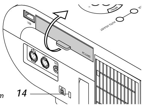
text_image
USB PC-CARD JSSOCK GLAW 14Slot for Kensington
MicroSaver Security System
10. RGB Audio Input 2 Connector
This is where you connect RGB audio output from a computer or another RGB source.
RGB Input 2 Connector (Mini D-Sub 15 pin)
Connect your PC or other RGB equipment. Use the signal cable that's supplied to connect to a PC.
11. S-Video Input Port
Here is where you connect the S-Video input from an external source like a VCR.
12. Left Channel/Mono Audio Input Jack (RCA)
This is the left channel audio input for stereo sound coming from video equipment or audio system. This also serves as your monaural audio input. (Video and S-video only)
Right Channel Audio Input Jack (RCA)
This is the right channel audio input for stereo sound. (Video and S-video only)
NOTE: When using two Video sources simultaneously, the Left Channel Audio Input jack is available for the S-Video source only and the Right Channel Audio Input jack is available for the composite video source only.
13. Video Input
Connect a VCR, DVD player, laser disc player, or document camera here to project video.
14. Built-in Security Slot ( ☑ )
This security slot supports the MicroSaver ^® Security System. MicroSaver ^® is a registered trademark of Kensington Microwave Inc. The logo is trademarked and owned by Kensington Microwave Inc.
Remote Control Features
NOTE: If you are using a Macintosh computer, you can click either the right-click or left-click button to activate the mouse.
NOTE: If any one of the buttons is pressed and held for 60 seconds or more, the button operations will cease to operate. This is not a malfunction, rather it is a feature used to prolong battery power. To cancel this feature, press any one of the buttons other than the Mouse button.
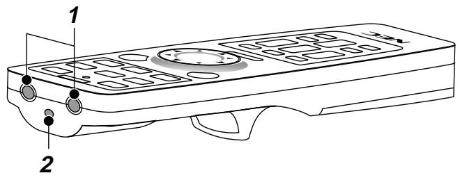
1. Infrared Transmitter
Direct the remote control toward the remote sensor on the projector cabinet.
2. Laser Pointer
Beams a laser light when "Laser" button is pressed.
text_image
1 2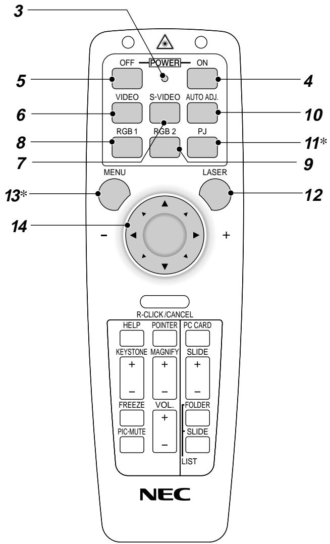
text_image
3 OFF POWER ON 5 VIDEO S-VIDEO AUTO ADJ. 6 RGB 1 RGB 2 PJ 7 MENU LASER 13* 14 - + R-CLICK/CANCEL HELP POINTER PC CARD KEYSTONE MAGNIFY SLIDE + + - - FREEZE VOL. FOLDER PIC-MUTE + SLIDE - LIST NEC3. LED
Flashes when any button is pressed.
4. Power On Button
If the main power is applied, you can use this button to turn your projector on.
5. Power Off Button
If the main power is applied, you can use this button to turn your projector off.
NOTE: To turn off the projector, press and hold the POWER OFF button for a minimum of two seconds.
6. Video Button
Press this button to select an NTSC, PAL, SECAM or NTSC4.43 compatible video source from a VCR, DVD player, laser disc player or document camera.
7. S-Video Button
Press this button to select an S-Video source from a VCR.
8. RGB 1 Button
Press this button to select a video source from computer or component equipment connected to your RGB 1 port.
9. RGB 2 Button
Press this button to select a video source from computer or component equipment connected to your RGB 2 port.
10. Auto Adjust Button (RGB only)
Press this button to automatically adjust the vertical/horizontal position, clock frequency/phase and resolution if the projected picture is not centered, if there are vertical stripes on the picture or if the picture is flickering.
11. PJ Button
Press this button to switch the Mouse, Cancel/Right Click, and Enter/Left Click buttons between the Projector mode (lit red) and the Computer mode. Press this button or any one of the Menu, Help, Pointer, PC Card, Folder List or Slide List buttons to switch to the Projector mode and the PJ button lights red. To switch back to the Computer mode, press the PJ button again.
12. Laser Button
Press and hold this button to activate the laser pointer. When lit, you can use the laser to draw your audience's attention to a red dot that you can place on any object.
13. Menu Button
Displays the menu for various settings and adjustments.
14. Mouse (▲▼◀▶) / (+) (-) Button
When you are in the Computer mode, these buttons work as a computer mouse.
When you are in the Projector mode, which is indicated by lighting the PJ button:
▲▼: Use these buttons to select the menu of the item you wish to adjust.
◀▶: Use these buttons to change the level of a selected menu item. A press of the ▶ button executes the selection.
When the pointer is displayed, these ▲▼◀▶ buttons move the pointer.
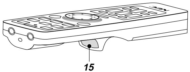
15. Enter / Left Click Button
When you are in the Computer mode, this button works as the mouse left button.
When you are in the Projector mode, which is indicated by lighting the PJ button:
Use this button to enter your menu selection. It works the same way as the "Enter" button on the cabinet.
text_image
15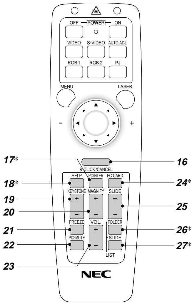
text_image
OFF POWER ON VIDEO S-VIDEO AUTO ADJ. RGB 1 RGB 2 PJ MENU LASER - + 17* R-CLICK/CANCEL 18* HELP POINTER PC CARD KEYSTONE MAGNIFY SLIDE 20 - - FREEZE VOL. FOLDER 21 PIC-MUTE SLIDE 22 - LIST 23 NEC 16 24* 25 26* 27*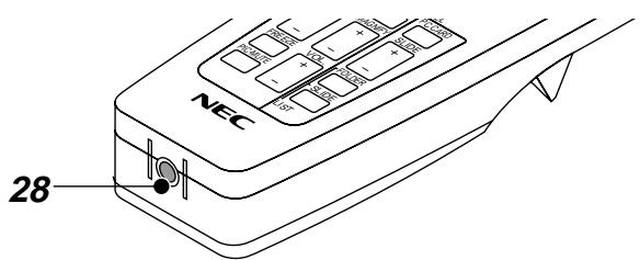
text_image
NEC 2816. Cancel/ Right Click Button
When you are in the Computer mode, this button works as the mouse right button.
When you are in the Projector mode, which is indicated by lighting the PJ button:
Press this button to exit "Menus". It works the same way as the "Cancel" button on the cabinet.
17. Pointer Button
Press this button to display one of the eight pointers; press again to hide the pointer. You can move your pointer icon to the area you want on the screen using the Mouse button.
18. Help Button
Provides information about operation and adjustment procedures or the set information for the current menu or adjustment during menu operation.
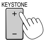
19. Keystone (+) (-) Button
Press the (+) or (−) button to correct the keystone (trapezoidal) distortion, and make the image square.
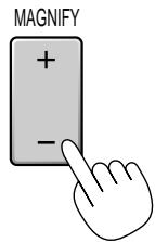
20. Magnify (+) (-) Button
Use this button to adjust the image size up to 400%.
When the pointer is displayed, the image is magnified about the center of the pointer. When the pointer is not displayed, the image is magnified about the center of the screen.
When the image is magnified, the pointer is changed to the magnifying icon.
21. Freeze Button
This button will freeze a picture. Press again to resume motion.
22. Picture Mute Button
This button turns off the image and sound for a short period of time. Press again to restore the image and sound.
NOTE: When the menu is displayed, a press of this button mutes an image and sound without turning off the menu.
23. Volume (+) (-) Button
Press (+) to increase the volume and (−) to decrease it.
24. PC Card Button
Press this button to select the PC Card Viewer source.
25. Slide (+) (-) Button
Press (+) to select the next folder or slide and (−) to select the previous folder or slide.
26. Folder List Button
Press this button to select PC Card Viewer source to display a list of folders included in a PC card.
27. Slide List Button
Press this button to select PC Card Viewer source to display a list of slides included in a PC card.
28. Remote Jack
Connect your remote control cable here for wired operation.
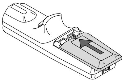
Remote Control Battery Installation
- Press firmly and slide the battery cover off.
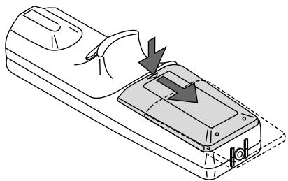
natural_image
Diagram of a device with arrows indicating movement or force, no text or symbols present- Remove both old batteries and install new ones (AA). Ensure that you have the batteries' polarity (+/-) aligned correctly.
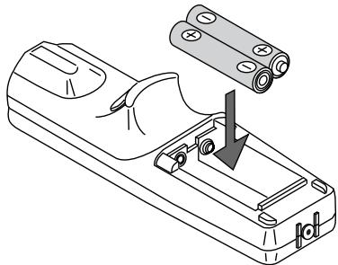
natural_image
Line drawing of a remote control device with a handle and internal components, showing no text or symbols- Slip the cover back over the batteries until it snaps into place.
natural_image
Line drawing of a remote control device with an arrow indicating the internal component (no text or symbols present)Do not mix different types of batteries or new and old batteries.
Operating Range
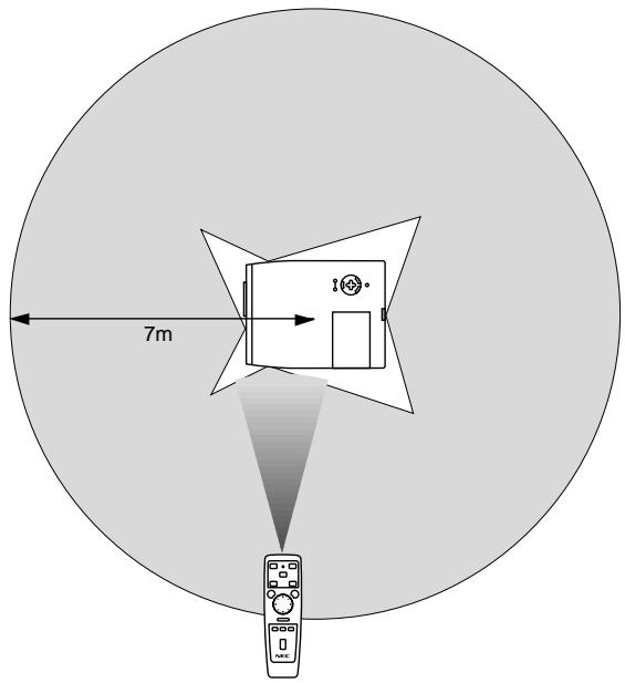
text_image
7m 10°Remote Control Precautions
- Handle the remote control carefully.
- If the remote control gets wet, wipe it dry immediately.
- Avoid excessive heat and humidity.
- If you will not be using the remote control for a long time, remove the batteries.
- Do not place the batteries upside down.
- Do not look into the laser pointer while it is on.
- Do not point the laser beam at a person.
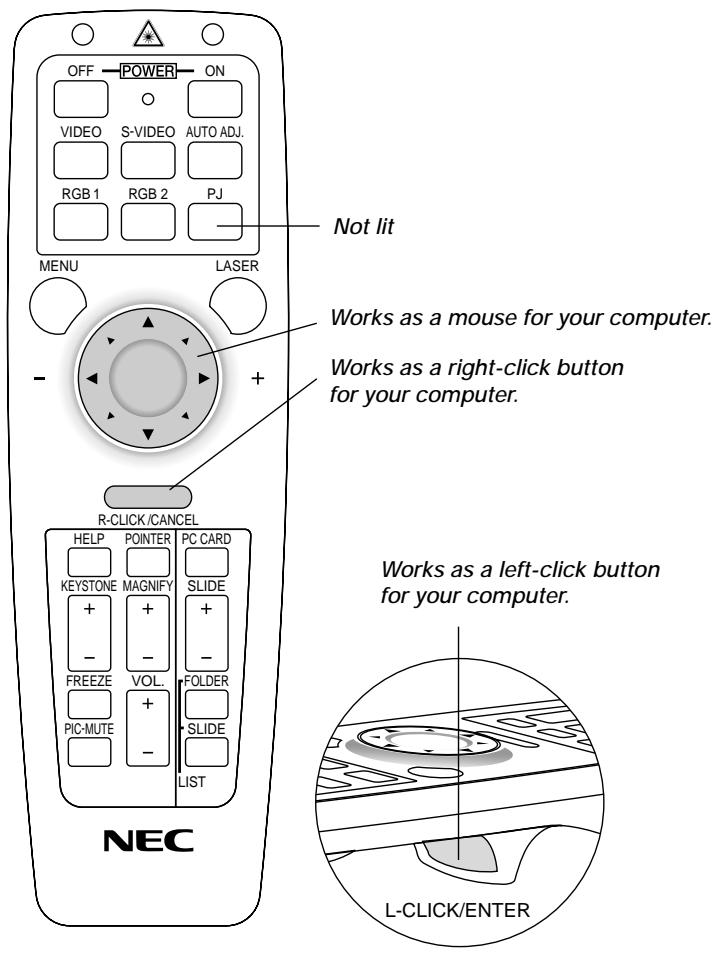
Switching operation mode between mouse and projector
The three shaded buttons shown on the drawing work as a computer mouse in the Computer mode. In the Computer mode the PJ button is not lit.
- When the MENU button is pressed, the PJ button lights red to indicate that you are in the Projector mode, which allows the projector menu operation using the three buttons.
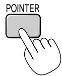
- When the POINTER button is pressed, the PJ button lights red to indicate that you are in the Projector mode and that the MOUSE ▲▼◀▶ button works as a moving button for the POINTER or magnified image.
- If no buttons are pressed within 10 seconds, the PJ button's light goes out to indicate that you are in the Computer mode. To enable the projector menu operation again, press the PJ button to light red. To move the pointer or a magnified image again, turn off the pointer and then turn on the pointer (press the POINTER button two times).
- When the PJ button is lit, if you want to use the mouse function immediately, press the PJ button to return to the Computer mode (not lit).
text_image
OFF POWER ON VIDEO S-VIDEO AUTO ADJ. RGB 1 RGB 2 PJ MENU LASER Not lit Works as a mouse for your computer. Works as a right-click button for your computer. R-CLICK/CANCEL HELP POINTER PC CARD KEystone MAGNIFY SLIDE + - FREEZE VOL. FOLDER PIC-MUTE + - LIST NEC Works as a left-click button for your computer. L-CLICK/ENTER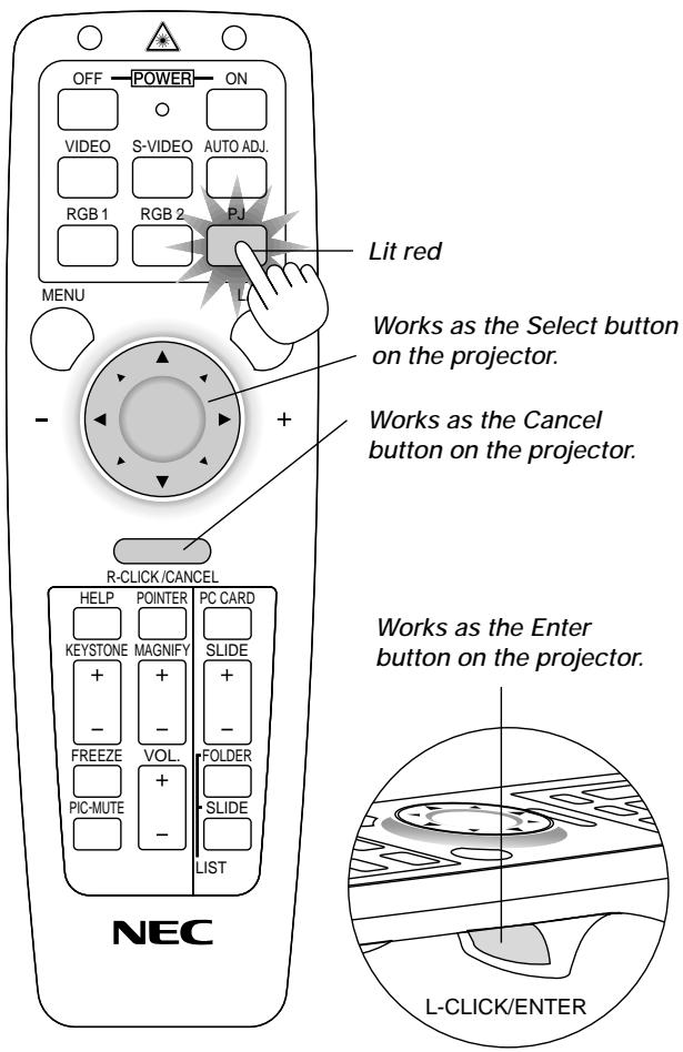
text_image
OFF POWER ON VIDEO S-VIDEO AUTO ADJ. RGB 1 RGB 2 PJ LIT red MENU - + Works as the Select button on the projector. Works as the Cancel button on the projector. R-CLICK/CANCEL HELP POINTER PC CARD KEystone MAGNIFY SLIDE + - FREEZE VOL FOLDER PIC-MUTE SLIDE LIST NEC Works as the Enter button on the projector. L-CLICK/ENTER2. INSTALLATION
This section describes how to set up your MultiSync MT1055/MT1050/MT850 projector and how to connect video and audio sources.
Setting up Your Projector
Your MultiSync MT1055/MT1050/MT850 Projector is simple to set up and use. But before you get started, you must first:
- Determine the image size.
- Set up a screen or select a non-glossy white wall onto which you can project your image.
Carrying the Projector: Always carry your projector by the handle. Ensure that the power cable and any other cables connecting to video sources are disconnected before moving the projector.
When moving the projector or when it is not in use, cover the lens with the lens cap.
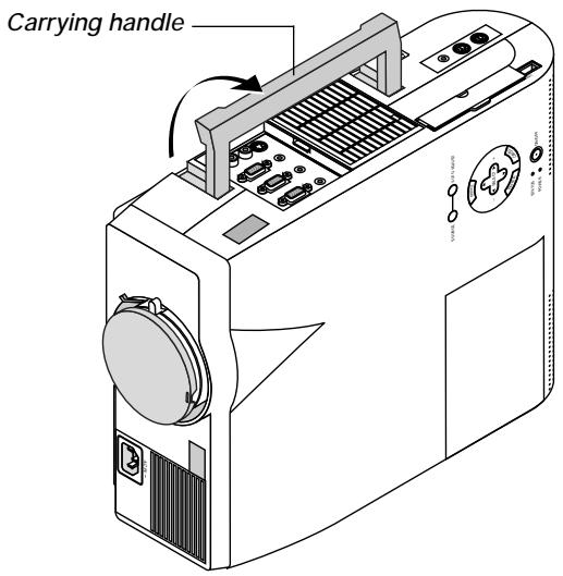
text_image
Carrying handleAttaching the lens cap to the lens hood with the supplied string and rivet.
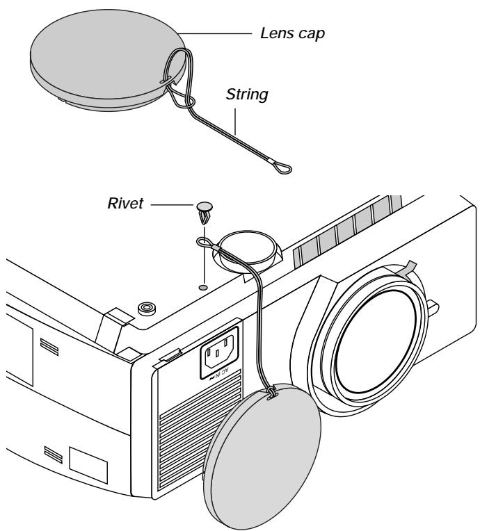
text_image
Lens cap String RivetSelecting a Location
The further your projector is from the screen or wall, the larger the image. The minimum size the image can be is approximately 30" (0.76 m) measured diagonally when the projector is roughly 4 feet (1.3 m) from the wall or screen. The largest the image can be is 300" (7.6 m) when the projector is about 36.8 feet (11.2 m) from the wall or screen.
Using a Tabletop or Cart
- Place your projector on a flat level surface at the optimal distance from the screen or wall so you realize the size image you want. (Avoid having bright room lighting or sun light directly on the screen or wall where you'll be projecting the image.)
-
Connect the power cable, remove the lens cap and turn the projector on. (If no input signal is available, the projector will display a background image.)
-
Ensure that the projector is square to the screen.
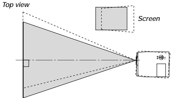
text_image
Top view Screen-
Move the projector left or right to center the image horizontally on the screen.
-
To center the image vertically, lift the front edge of the projector and press the One-Touch Tilt button on the front-left side of the projector to release the Front Adjustable foot.
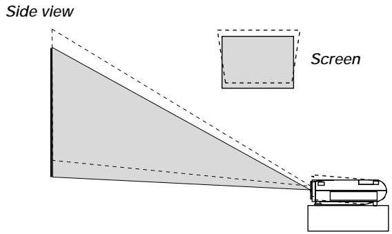
text_image
Side view Screen(There is approximately 5 degrees of up and down adjustment for the front of the projector.)
-
If the projected image does not appear square to the screen then use keystone correction for proper adjustment.
-
Adjust the size of the image using the Zoom ring on the lens.
Adjusting the Tilt Foot
Press and hold the Tilt button on the left side of the projector.
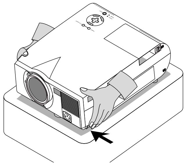
natural_image
Illustration of a projector with hands operating it, showing no text or symbols on the device itselfLift the front edge of the projector to the height you want, and release the button to lock the Adjustable Tilt Foot.
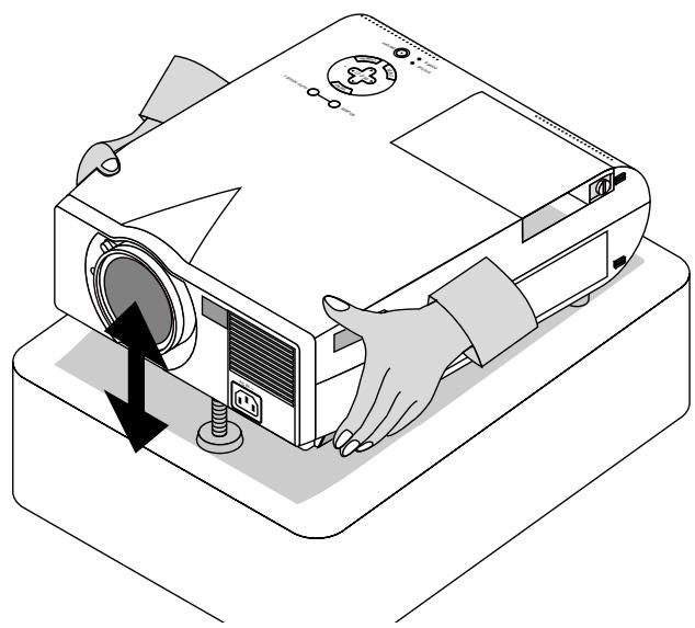
natural_image
Illustration of a projector with a hand operating the base and a black arrow indicating motion (no text or symbols)To fine-tune the image's position vertically on the screen, rotate the foot. Each of the rear feet height can be changed up to 0.6" (4mm).
Distance Chart
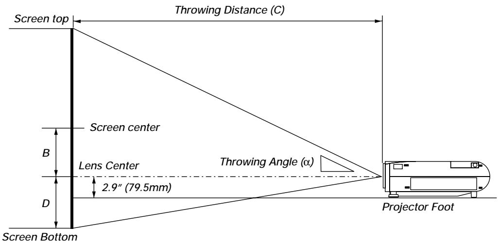
text_image
Screen top Throwing Distance (C) Screen center B Lens Center D 2.9" (79.5mm) Throwing Angle (α) Projector Foot Screen BottomB=Vertical distance between lens center and screen center
C=Throw distance
D=Vertical distance between lens center and screen bottom (screen top for ceiling installation)
Ceiling Installation
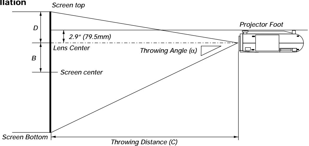
text_image
Iulation Screen top D 2.9" (79.5mm) Lens Center B Screen center Throwing Angle (α) Projector Foot Screen Bottom Throwing Distance (C)WARNING
- Installing your projector on the ceiling must be done by a qualified technician. Contact your NEC dealer for more information.
* Do not attempt to install the projector yourself. - Only use your projector on a solid, level surface. If the projector falls to the ground, you can be injured and the projector severely damaged.
- Do not use the projector where temperatures vary greatly. The projector must be used at temperatures between 32^ F ( 0^ C) and 104^ F ( 40^ C).
- Do not expose the projector to moisture, dust, or smoke. This will harm the screen image.
- Ensure that you have adequate ventilation around your projector so heat can dissipate. Do not cover the vents on the side or the front of the projector.
If your projector is mounted on the ceiling and your image is upside down, use the "Menu" and "Select" buttons on your projector cabinet or ▲▼ button on your remote control to correct the orientation. (See page E-36.)
Reflecting the Image
Using a mirror to reflect your projector's image enables you to enjoy a much larger image. Contact your NEC dealer if you need a mirror. If you're using a mirror and your image is inverted, use the "Menu" and "Select" buttons on your projector cabinet or ▲▼ buttons on your remote control to correct the orientation. (See page E-36.)
MT1055
| Screen Size | B | C | D | α | ||||||||||||
| Diagonal | Width | Height | wide | telephoto | wide | telephoto | ||||||||||
| 40 | inch | 32 | inch | 24 | inch | 10.2 | inch | 56.3 | inch | - | 68.6 | inch | 1.8 | inch | 10.3 degree | - 8.5 degree |
| 1016 | mm | 812.8 | mm | 609.6 | mm | 259.5 | mm | 1430.3 | mm | 1743.7 | mm | 45.3 | mm | |||
| 60 | inch | 48 | inch | 36 | inch | 15.3 | inch | 86.1 | inch | - | 104.3 | inch | 2.7 | inch | 10.1 degree | - 8.4 degree |
| 1524 | mm | 1219.2 | mm | 914.4 | mm | 389.2 | mm | 2185.8 | mm | 2649.9 | mm | 68.0 | mm | |||
| 67 | inch | 53.6 | inch | 40.2 | inch | 17.1 | inch | 96.5 | inch | - | 116.8 | inch | 3.0 | inch | 10.1 degree | - 8.3 degree |
| 1701.8 | mm | 1361.44 | mm | 1021.08 | mm | 434.7 | mm | 2450.2 | mm | 2967.1 | mm | 75.9 | mm | |||
| 72 | inch | 57.6 | inch | 43.2 | inch | 18.4 | inch | 103.9 | inch | - | 125.7 | inch | 3.2 | inch | 10.0 degree | - 8.3 degree |
| 1828.8 | mm | 1463.04 | mm | 1097.28 | mm | 467.1 | mm | 2639.0 | mm | 3193.7 | mm | 81.5 | mm | |||
| 84 | inch | 67.2 | inch | 50.4 | inch | 21.5 | inch | 121.7 | inch | - | 147.1 | inch | 3.7 | inch | 10.0 degree | - 8.3 degree |
| 2133.6 | mm | 1706.88 | mm | 1280.16 | mm | 544.9 | mm | 3092.3 | mm | 3737.4 | mm | 95.1 | mm | |||
| 90 | inch | 72 | inch | 54 | inch | 23.0 | inch | 130.7 | inch | - | 157.8 | inch | 4.0 | inch | 10.0 degree | - 8.3 degree |
| 2286 | mm | 1828.8 | mm | 1371.6 | mm | 583.9 | mm | 3318.9 | mm | 4009.3 | mm | 101.9 | mm | |||
| 100 | inch | 80 | inch | 60 | inch | 25.5 | inch | 145.5 | inch | - | 175.7 | inch | 4.5 | inch | 10.0 degree | - 8.3 degree |
| 2540 | mm | 2032 | mm | 1524 | mm | 648.7 | mm | 3696.6 | mm | 4462.4 | mm | 113.3 | mm | |||
| 120 | inch | 96 | inch | 72 | inch | 30.6 | inch | 175.3 | inch | - | 211.4 | inch | 5.4 | inch | 9.9 degree | - 8.3 degree |
| 3048 | mm | 2438.4 | mm | 1828.8 | mm | 778.5 | mm | 4452.1 | mm | 5368.7 | mm | 135.9 | mm | |||
| 150 | inch | 120 | inch | 90 | inch | 38.3 | inch | 219.9 | inch | - | 264.9 | inch | 6.7 | inch | 9.9 degree | - 8.2 degree |
| 3810 | mm | 3048 | mm | 2286 | mm | 973.1 | mm | 5585.2 | mm | 6728.0 | mm | 169.9 | mm | |||
| 180 | inch | 144 | inch | 108 | inch | 46.0 | inch | 264.5 | inch | - | 318.4 | inch | 8.0 | inch | 9.9 degree | - 8.2 degree |
| 4572 | mm | 3657.6 | mm | 2743.2 | mm | 1167.7 | mm | 6718.4 | mm | 8087.4 | mm | 203.9 | mm | |||
| 210 | inch | 168 | inch | 126 | inch | 53.6 | inch | 309.1 | inch | - | 371.9 | inch | 9.4 | inch | 9.8 degree | - 8.2 degree |
| 5334 | mm | 4267.2 | mm | 3200.4 | mm | 1362.3 | mm | 7851.5 | mm | 9446.8 | mm | 237.9 | mm | |||
| 240 | inch | 192 | inch | 144 | inch | 61.3 | inch | 353.7 | inch | - | 425.4 | inch | 10.7 | inch | 9.8 degree | - 8.2 degree |
| 6096 | mm | 4876.8 | mm | 3657.6 | mm | 1557.0 | mm | 8984.7 | mm | 10806.2 | mm | 271.8 | mm | |||
| 270 | inch | 216 | inch | 162 | inch | 69.0 | inch | 398.3 | inch | - | 479.0 | inch | 12.0 | inch | 9.8 degree | - 8.2 degree |
| 6858 | mm | 5486.4 | mm | 4114.8 | mm | 1751.6 | mm | 10117.8 | mm | 12165.5 | mm | 305.8 | mm | |||
| 300 | inch | 240 | inch | 180 | inch | 76.6 | inch | 443.0 | inch | - | 532.5 | inch | 13.4 | inch | 9.8 degree | - 8.2 degree |
| 7620 | mm | 6096 | mm | 4572 | mm | 1946.2 | mm | 11251.0 | mm | 13524.9 | mm | 339.8 | mm | |||
MT1050
| Diagonal | Screen Size | B | C | D | α | |||||||||||||
| Width | Height | wide | telephoto | wide | telephoto | |||||||||||||
| 40 | inch | 32 | inch | 24 | inch | 10.2 | inch | 56.5 | inch | - | 68.2 | inch | 1.8 | inch | 10.3 | degree | - | 8.5 degree |
| 1016 | mm | 812.8 | mm | 609.6 | mm | 259.5 | mm | 1434.7 | mm | 1732.7 | mm | 45.3 | mm | |||||
| 60 | inch | 48 | inch | 36 | inch | 15.3 | inch | 85.8 | inch | - | 103.4 | inch | 2.7 | inch | 10.1 | degree | - | 8.4 degree |
| 1524 | mm | 1219.2 | mm | 914.4 | mm | 389.2 | mm | 2179.8 | mm | 2626.7 | mm | 68.0 | mm | |||||
| 67 | inch | 53.6 | inch | 40.2 | inch | 17.1 | inch | 96.1 | inch | - | 115.7 | inch | 3.0 | inch | 10.1 | degree | - | 8.4 degree |
| 1701.8 | mm | 1361.44 | mm | 1021.08 | mm | 434.7 | mm | 2440.5 | mm | 2939.7 | mm | 75.9 | mm | |||||
| 72 | inch | 57.6 | inch | 43.2 | inch | 18.4 | inch | 103.4 | inch | - | 124.5 | inch | 3.2 | inch | 10.1 | degree | - | 8.4 degree |
| 1828.8 | mm | 1463.04 | mm | 1097.28 | mm | 467.1 | mm | 2626.8 | mm | 3163.2 | mm | 81.5 | mm | |||||
| 84 | inch | 67.2 | inch | 50.4 | inch | 21.5 | inch | 121.0 | inch | - | 145.7 | inch | 3.7 | inch | 10.1 | degree | - | 8.4 degree |
| 2133.6 | mm | 1706.88 | mm | 1280.16 | mm | 544.9 | mm | 3073.8 | mm | 3699.6 | mm | 95.1 | mm | |||||
| 90 | inch | 72 | inch | 54 | inch | 23.0 | inch | 129.8 | inch | - | 156.2 | inch | 4.0 | inch | 10.0 | degree | - | 8.4 degree |
| 2286 | mm | 1828.8 | mm | 1371.6 | mm | 583.9 | mm | 3297.3 | mm | 3967.8 | mm | 101.9 | mm | |||||
| 100 | inch | 80 | inch | 60 | inch | 25.5 | inch | 144.5 | inch | - | 173.8 | inch | 4.5 | inch | 10.0 | degree | - | 8.4 degree |
| 2540 | mm | 2032 | mm | 1524 | mm | 648.7 | mm | 3669.8 | mm | 4414.8 | mm | 113.3 | mm | |||||
| 120 | inch | 96 | inch | 72 | inch | 30.6 | inch | 173.8 | inch | - | 209.0 | inch | 5.4 | inch | 10.0 | degree | - | 8.3 degree |
| 3048 | mm | 2438.4 | mm | 1828.8 | mm | 778.5 | mm | 4414.9 | mm | 5308.9 | mm | 135.9 | mm | |||||
| 150 | inch | 120 | inch | 90 | inch | 38.3 | inch | 217.8 | inch | - | 261.8 | inch | 6.7 | inch | 10.0 | degree | - | 8.3 degree |
| 3810 | mm | 3048 | mm | 2286 | mm | 973.1 | mm | 5532.4 | mm | 6649.9 | mm | 169.9 | mm | |||||
| 180 | inch | 144 | inch | 108 | inch | 46.0 | inch | 261.8 | inch | - | 314.6 | inch | 8.0 | inch | 10.0 | degree | - | 8.3 degree |
| 4572 | mm | 3657.6 | mm | 2743.2 | mm | 1167.7 | mm | 6650.0 | mm | 7991.0 | mm | 203.9 | mm | |||||
| 210 | inch | 168 | inch | 126 | inch | 53.6 | inch | 305.8 | inch | - | 367.4 | inch | 9.4 | inch | 9.9 | degree | - | 8.3 degree |
| 5334 | mm | 4267.2 | mm | 3200.4 | mm | 1362.3 | mm | 7767.6 | mm | 9332.0 | mm | 237.9 | mm | |||||
| 240 | inch | 192 | inch | 144 | inch | 61.3 | inch | 349.8 | inch | - | 420.2 | inch | 10.7 | inch | 9.9 | degree | - | 8.3 degree |
| 6096 | mm | 4876.8 | mm | 3657.6 | mm | 1557.0 | mm | 8885.1 | mm | 10673.1 | mm | 271.8 | mm | |||||
| 270 | inch | 216 | inch | 162 | inch | 69.0 | inch | 393.8 | inch | - | 473.0 | inch | 12.0 | inch | 9.9 | degree | - | 8.3 degree |
| 6858 | mm | 5486.4 | mm | 4114.8 | mm | 1751.6 | mm | 10002.7 | mm | 12014.1 | mm | 305.8 | mm | |||||
| 300 | inch | 240 | inch | 180 | inch | 76.6 | inch | 437.8 | inch | - | 525.8 | inch | 13.4 | inch | 9.9 | degree | - | 8.3 degree |
| 7620 | mm | 6096 | mm | 4572 | mm | 1946.2 | mm | 11120.3 | mm | 13355.2 | mm | 339.8 | mm | |||||
MT850
| T850 | Screen Size | B | C | D | α | |||||||||||||
| Diagonal | Width | Height | wide | telephoto | wide | telephoto | ||||||||||||
| 40 | inch | 32 | inch | 24 | inch | 10.3 | inch | 57.0 | inch | - | 68.8 | inch | 1.7 | inch | 10.2 | degree | - | 8.5 degree |
| 1016 | mm | 812.8 | mm | 609.6 | mm | 261.6 | mm | 1446.5 | mm | 1746.9 | mm | 43.2 | mm | |||||
| 60 | inch | 48 | inch | 36 | inch | 15.4 | inch | 86.5 | inch | - | 104.3 | inch | 2.6 | inch | 10.1 | degree | - | 8.4 degree |
| 1524 | mm | 1219.2 | mm | 914.4 | mm | 392.3 | mm | 2197.5 | mm | 2648.0 | mm | 64.9 | mm | |||||
| 67 | inch | 53.6 | inch | 40.2 | inch | 17.2 | inch | 96.9 | inch | - | 116.7 | inch | 2.9 | inch | 10.1 | degree | - | 8.4 degree |
| 1701.8 | mm | 1361.44 | mm | 1021.08 | mm | 438.1 | mm | 2460.3 | mm | 2963.4 | mm | 72.4 | mm | |||||
| 72 | inch | 57.6 | inch | 43.2 | inch | 18.5 | inch | 104.3 | inch | - | 125.5 | inch | 3.1 | inch | 10.1 | degree | - | 8.4 degree |
| 1828.8 | mm | 1463.04 | mm | 1097.28 | mm | 470.8 | mm | 2648.1 | mm | 3188.7 | mm | 77.8 | mm | |||||
| 84 | inch | 67.2 | inch | 50.4 | inch | 21.6 | inch | 122.0 | inch | - | 146.8 | inch | 3.6 | inch | 10.1 | degree | - | 8.4 degree |
| 2133.6 | mm | 1706.88 | mm | 1280.16 | mm | 549.3 | mm | 3098.6 | mm | 3729.4 | mm | 90.8 | mm | |||||
| 90 | inch | 72 | inch | 54 | inch | 23.2 | inch | 130.9 | inch | - | 157.5 | inch | 3.8 | inch | 10.0 | degree | - | 8.4 degree |
| 2286 | mm | 1828.8 | mm | 1371.6 | mm | 588.5 | mm | 3323.9 | mm | 3999.7 | mm | 97.3 | mm | |||||
| 100 | inch | 80 | inch | 60 | inch | 25.7 | inch | 145.6 | inch | - | 175.2 | inch | 4.3 | inch | 10.0 | degree | - | 8.4 degree |
| 2540 | mm | 2032 | mm | 1524 | mm | 653.9 | mm | 3699.4 | mm | 4450.3 | mm | 108.1 | mm | |||||
| 120 | inch | 96 | inch | 72 | inch | 30.9 | inch | 175.2 | inch | - | 210.7 | inch | 5.1 | inch | 10.0 | degree | - | 8.3 degree |
| 3048 | mm | 2438.4 | mm | 1828.8 | mm | 784.7 | mm | 4450.4 | mm | 5351.4 | mm | 129.7 | mm | |||||
| 150 | inch | 120 | inch | 90 | inch | 38.6 | inch | 219.6 | inch | - | 263.9 | inch | 6.4 | inch | 10.0 | degree | - | 8.3 degree |
| 3810 | mm | 3048 | mm | 2286 | mm | 980.8 | mm | 5576.8 | mm | 6703.1 | mm | 162.2 | mm | |||||
| 180 | inch | 144 | inch | 108 | inch | 46.3 | inch | 263.9 | inch | - | 317.1 | inch | 7.7 | inch | 10.0 | degree | - | 8.3 degree |
| 4572 | mm | 3657.6 | mm | 2743.2 | mm | 1177.0 | mm | 6703.2 | mm | 8054.8 | mm | 194.6 | mm | |||||
| 210 | inch | 168 | inch | 126 | inch | 54.1 | inch | 308.3 | inch | - | 370.3 | inch | 8.9 | inch | 9.9 | degree | - | 8.3 degree |
| 5334 | mm | 4267.2 | mm | 3200.4 | mm | 1373.2 | mm | 7829.6 | mm | 9406.5 | mm | 227.0 | mm | |||||
| 240 | inch | 192 | inch | 144 | inch | 61.8 | inch | 352.6 | inch | - | 423.6 | inch | 10.2 | inch | 9.9 | degree | - | 8.3 degree |
| 6096 | mm | 4876.8 | mm | 3657.6 | mm | 1569.3 | mm | 8956.1 | mm | 10758.2 | mm | 259.5 | mm | |||||
| 270 | inch | 216 | inch | 162 | inch | 69.5 | inch | 396.9 | inch | - | 476.8 | inch | 11.5 | inch | 9.9 | degree | - | 8.3 degree |
| 6858 | mm | 5486.4 | mm | 4114.8 | mm | 1765.5 | mm | 10082.5 | mm | 12109.9 | mm | 291.9 | mm | |||||
| 300 | inch | 240 | inch | 180 | inch | 77.2 | inch | 441.3 | inch | - | 530.0 | inch | 12.8 | inch | 9.9 | degree | - | 8.3 degree |
| 7620 | mm | 6096 | mm | 4572 | mm | 1961.7 | mm | 11208.9 | mm | 13461.6 | mm | 324.3 | mm | |||||
NOTE: Distances may vary +/-5%.
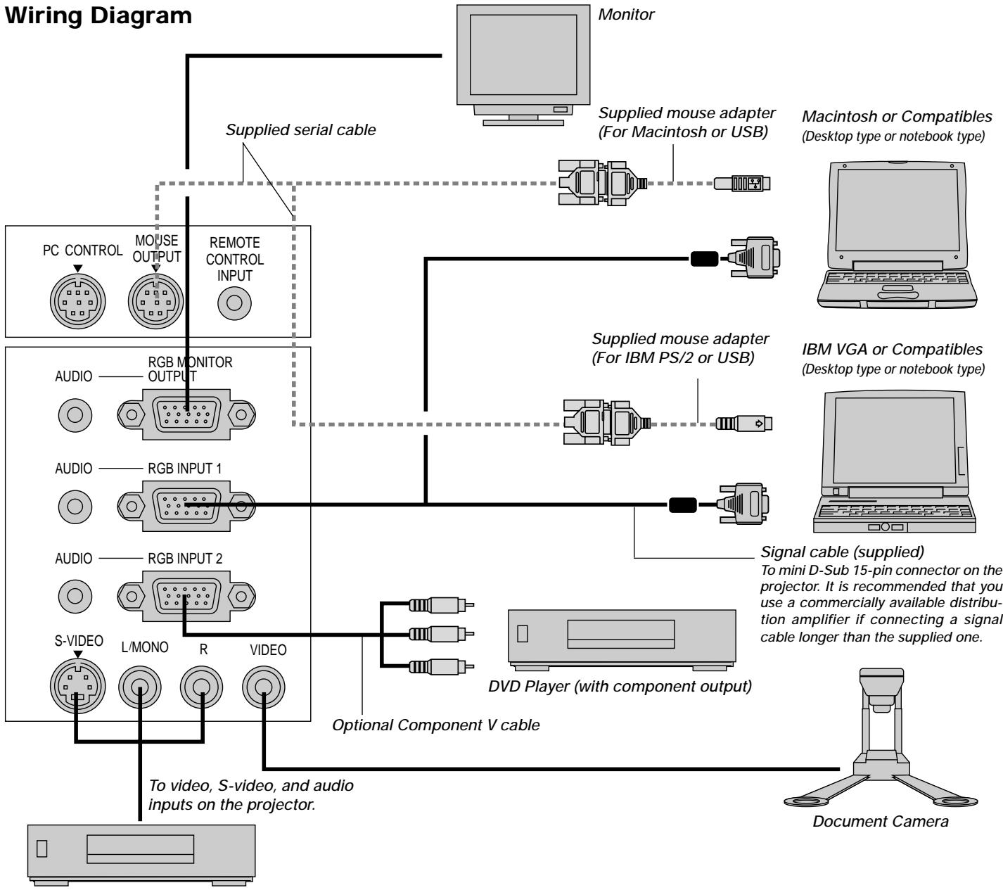
flowchart
graph TD
    A["PC CONTROL"] --> B["MOUSE OUTPUT"]
    B --> C["REMOTE CONTROL INPUT"]
    C --> D["RGB MONITOR OUTPUT"]
    D --> E["AUDIO"]
    E --> F["RGB INPUT 1"]
    F --> G["AUDIO"]
    G --> H["RGB INPUT 2"]
    H --> I["S-VIDEO"]
    I --> J["L/MONO"]
    J --> K["R"]
    K --> L["VIDEO"]
    L --> M["Document Camera"]
    N["Monitor"] --> O["Supplied mouse adapter (For Macintosh or USB)"]
    O --> P["Macintosh or Compatibles (Desktop type or notebook type)"]
    P --> Q["IBM VGA or Compatibles (Desktop type or notebook type)"]
    Q --> R["Signal cable (supplied)"]
    R --> S["To mini D-Sub 15-pin connector on the projector. It is recommended that you use a commercially available distribution amplifier if connecting a signal cable longer than the supplied one."]
    T["DVD Player (with component output)"] --> U["Optional Component V cable"]
    U --> V["Video Inputs on the projector. To video, S-video, and audio inputs on the projector."]
VCR, DVD Player or LaserDisc Player
NOTE: When using with a notebook PC, be sure to connect between the projector and the notebook PC before turning on the power to the notebook PC. In most cases signal cannot be output from RGB output unless the notebook PC is turned on after connecting with the projector.
NOTE: If using video, S-video, or audio cables, the cables should be 3 m (9.8 feet) or shorter.
Remote Control Guideline for the Remote Control
- Plug the supplied serial cable with the mouse output port of the projector into your computer's mouse port and restart your computer to gain remote mouse control.
- When using the remote control's built-in infrared mouse on a laptop computer, the laptop's mouse, trackball or trackpad will be disabled. Disconnect the serial cable from the mouse output port and restart your computer to regain trackball or trackpad mouse control.
- If the screen goes blank while using your remote control, it may be the result of the computer's screen-saver or power management software.
- If you accidentally hit the OFF button on the remote control, wait one full minute and then press the ON button to resume.
Connecting Your PC or Macintosh Computer
Connecting your PC or Macintosh computer to your MultiSync MT1055 and MT1050 (XGA) / MT850 (SVGA) projector will enable you to project your computer's screen image for an impressive presentation.
To connect to a PC or Macintosh, simply:
- Turn off the power to your projector and computer.
- Use the signal cable that's supplied to connect your PC or Macintosh computer to the projector.
NOTE: The new Macintosh computer such as G3 will have the 15 pin HD connector. The MT1055/MT1050/MT850's "Plug and Play" data will be downloaded to the Macintosh. Therefore, the Mac adapter will not be necessary. - Turn on the projector and the computer.
- If the projector goes blank after a period of inactivity, it may be caused by a screen saver installed on the computer you've connected to the projector.
Connecting Your PC
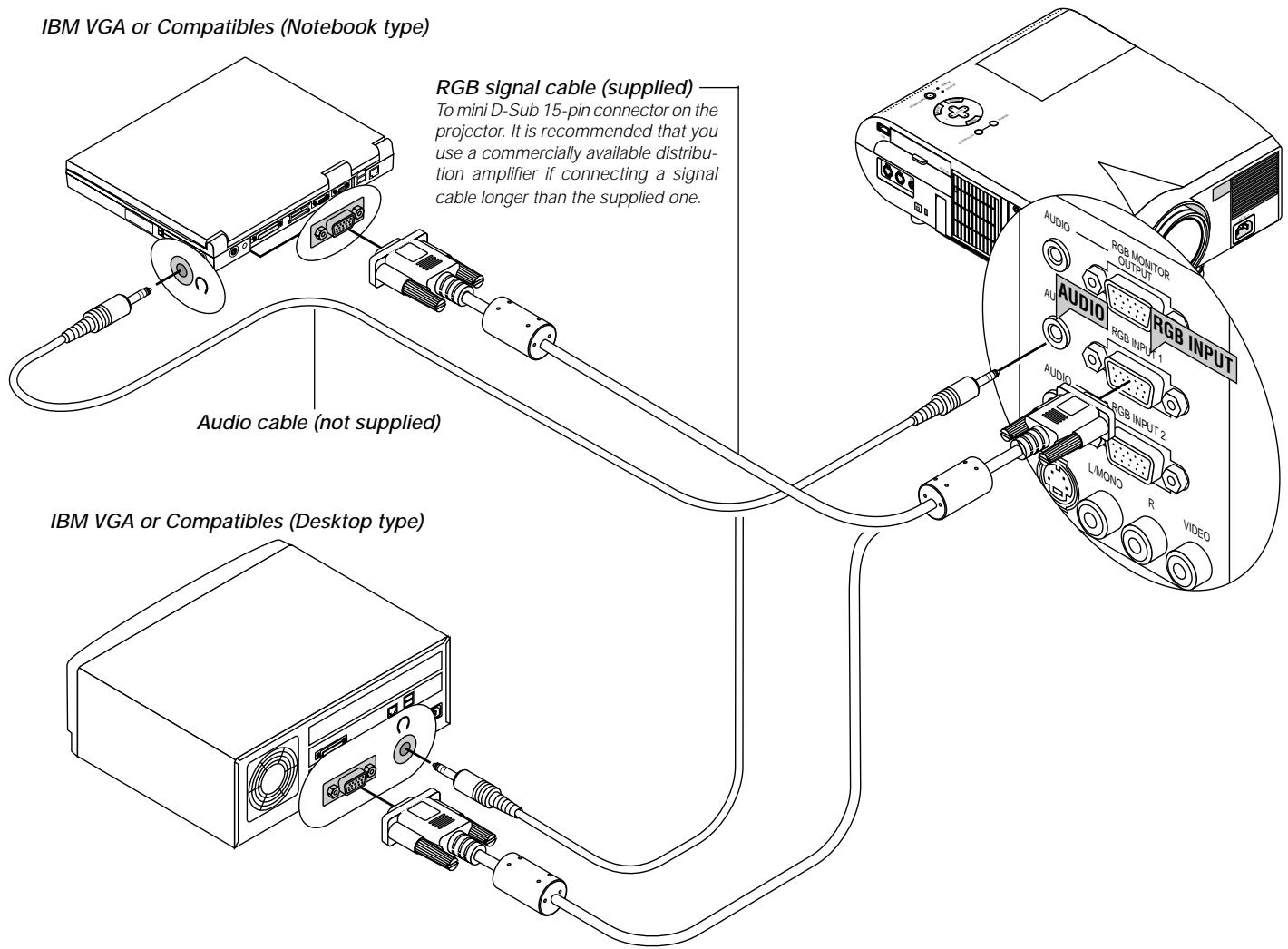
text_image
IBM VGA or Compatibles (Notebook type) RGB signal cable (supplied) To mini D-Sub 15-pin connector on the projector. It is recommended that you use a commercially available distribu- tion amplifier if connecting a signal cable longer than the supplied one. Audio cable (not supplied) IBM VGA or Compatibles (Desktop type)Connecting your PC to your MultiSync MT1055 and MT1050 (XGA)/MT850 (SVGA) projector will enable you to project your computer's screen image for an impressive presentation.
To connect to a PC, simply:
- Turn off the power to your projector and computer.
- Use the supplied signal cable to connect your PC to the projector.
- Turn on the projector and the computer.
- If the projector goes blank after a period of inactivity, it may be caused by a screen saver installed on the computer you've connected to the projector.
Connecting Your Macintosh Computer
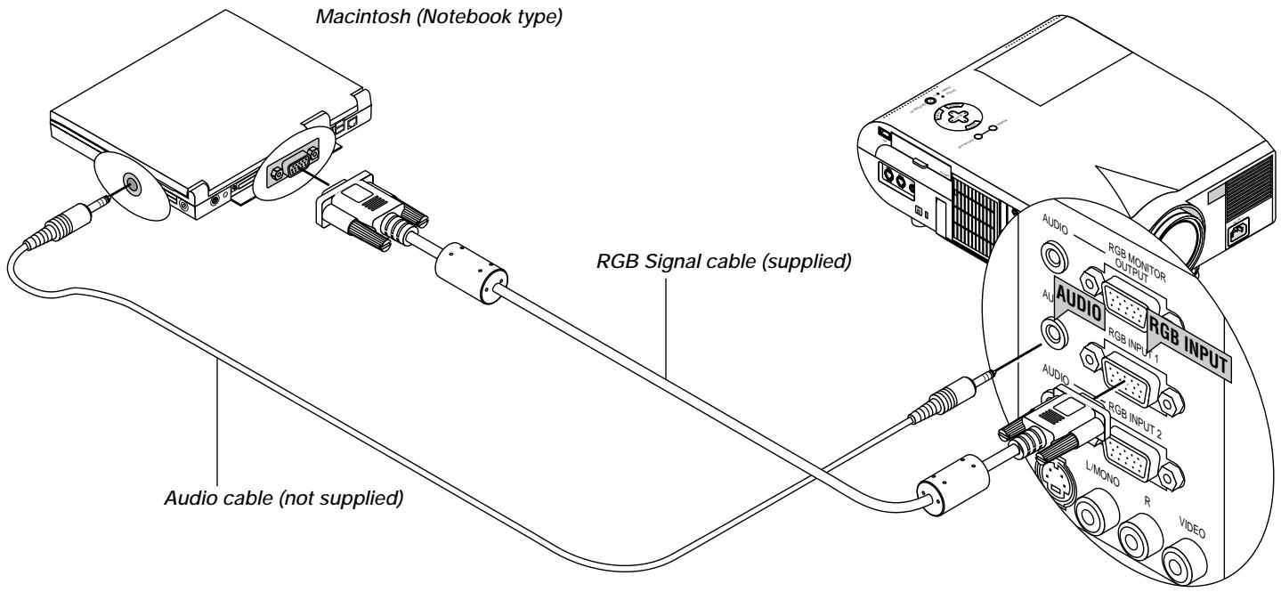
text_image
Macintosh (Notebook type) RGB Signal cable (supplied) Audio cable (not supplied) AUDIO RGB MONITOR OUTPUT AUDIO RGB INPUT 1 AUDIO RGB INPUT 2 L/MONO R VIDEOMacintosh (Desktop type)
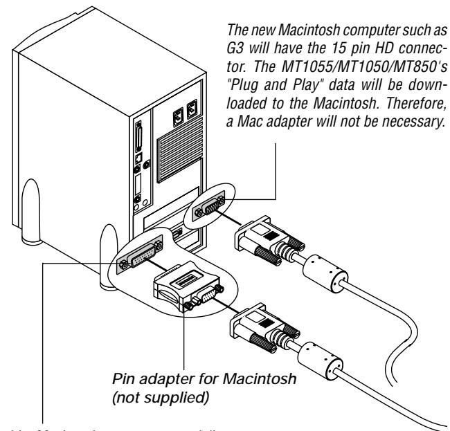
text_image
The new Macintosh computer such as G3 will have the 15 pin HD connector. The MT1055/MT1050/MT850's "Plug and Play" data will be downloaded to the Macintosh. Therefore, a Mac adapter will not be necessary. Pin adapter for Macintosh (not supplied)For older Macintosh, use a commercially available pin adapter to connect to your Mac's video port.
To connect to a Macintosh, simply:
- Turn off the power to your projector and your Macintosh computer.
- Use the supplied signal cable to connect your Macintosh computer to the projector.
- Turn on the projector and the Macintosh computer.
Connecting Your Computer to the Mouse Output Port
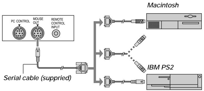
flowchart
graph TD
    A["PC CONTROL"] --> B["Mouse OUT"]
    B --> C["Remote CONTROL INPUT"]
    D["Serial cable (supplied)"] --> E["Macintosh"]
    D --> F["IBM PS2"]
    E --> G["Output"]
    F --> H["Output"]
The built-in remote mouse receiver enables you to operate your computer's mouse functions from the remote control. It is a great convenience for clicking through your computer-generated presentations.
To connect the mouse output port:
-
Turn off your computer.
-
For PCs: Remove your current mouse and connect the supplied serial cable from the mouse output to your PC's mouse port. (Use the 6-pin adapter for connecting to a PS/2 computer or the supplied USB adapter.)
For Macintosh: Remove your current mouse from your computer, attach the Macintosh adapter or the supplied USB adapter to the mouse output port's serial cable, and connect the projector to your mouse port.
- When the built-in remote mouse receiver is available, it will disable your regular mouse, disconnect the serial cable and restart your computer.
NOTE: The mouse adapter for USB is not compatible with the USB terminal on the projector.
Connecting an External Monitor
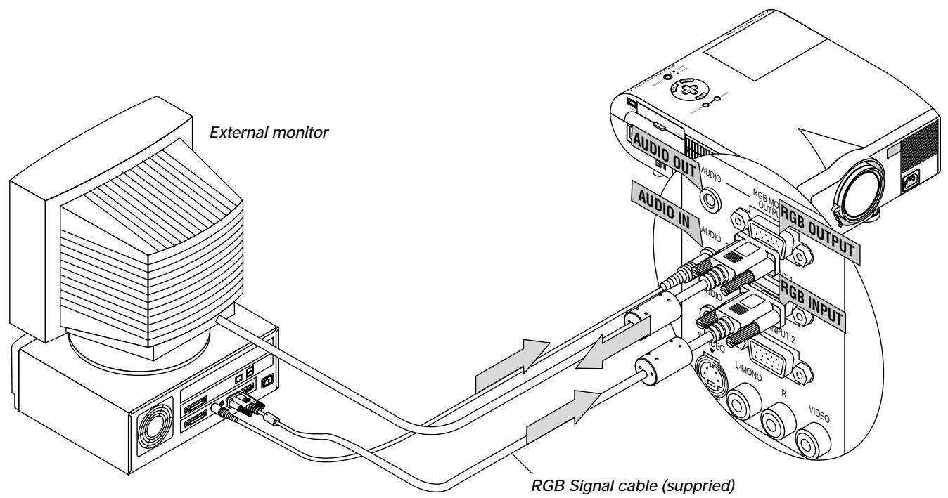
text_image
External monitor AUDIO OUT AUDIO RGB MC OUTPUT AUDIO IN AUDIO RGB OUTPUT RGB INPUT OUTPUT 2 L/MONO R VIDEO RGB Signal cable (suppried)You can connect a separate, external monitor to your MT1055/MT1050/MT850 to simultaneously view on a monitor the image you're projecting. To do so:
- Turn off the power to your projector, monitor and computer.
- Use a 15-pin cable to connect your monitor to the RGB Monitor Output (Mini D-Sub 15 pin) connector on your projector.
- Turn on the projector, monitor and the computer.
Connecting Your DVD Player
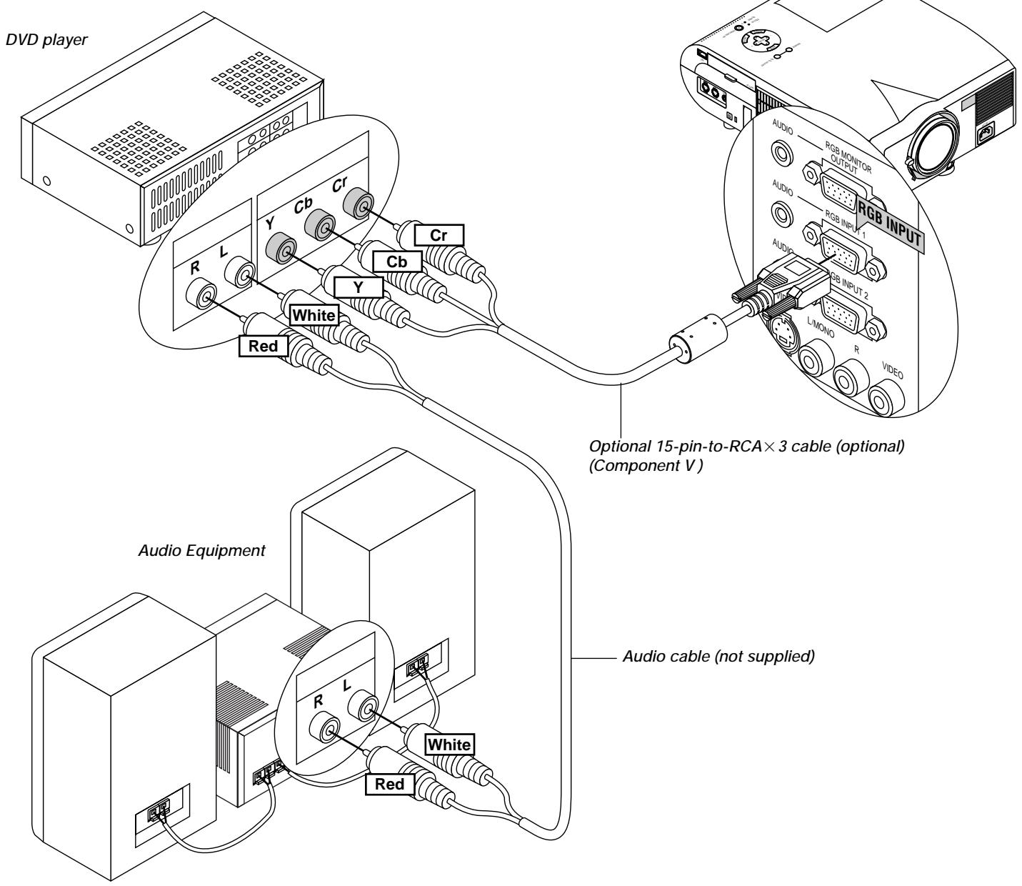
text_image
DVD player Cb Cr Cr Y Cb Y White Red Audio Equipment Audio cable (not supplied) Optional 15-pin-to-RCA×3 cable (optional) (Component V)You can connect your projector to a DVD player with component outputs or Video output. To do so, simply:
- Turn off the power to your projector and DVD player.
- If your DVD player has the component video (Y,Cb,Cr) output, use the optional 15-pin-to-RCA×3 cable to connect your DVD player to the RGB INPUT connector on the projector.
For a DVD player without component video (Y,Cb,Cr) outputs, use common RCA cables (not provided) to connect a composite VIDEO output of the DVD player to the Video Input of the projector. - Turn on the projector and DVD player.
NOTE: Refer to your DVD player's owner's manual for more information about your DVD player's video output requirements,
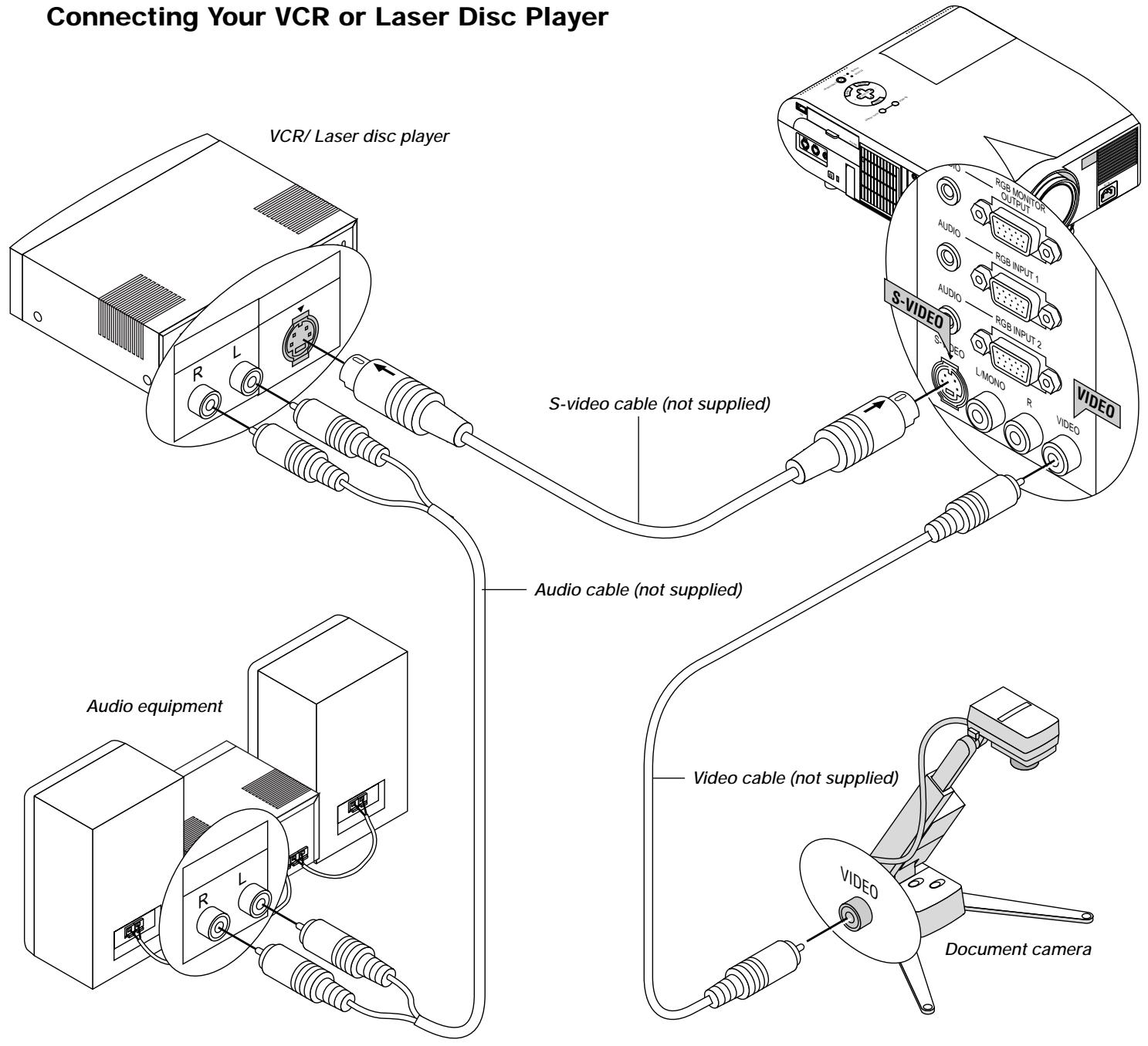
text_image
Connecting Your VCR or Laser Disc Player VCR/ Laser disc player S-video cable (not supplied) Audio cable (not supplied) Audio equipment Video cable (not supplied) Document cameraUse common RCA cables (not provided) to connect your VCR, laser disc player or document camera to your projector.
To make these connections, simply:
- Turn off the power to the projector and VCR, laser disc player or document camera.
- Connect one end of your RCA cable to the video output connector on the back of your VCR or laser disc player, connect the other end to the Video input on your projector. Use an audio cable (not supplied) to connect the audio from your VCR or laser disc player to your audio equipment (if your VCR or laser disc player has this capability). Be careful to keep your right and left channel connections correct for stereo sound.
- Turn on the projector and the VCR or laser disc player.
NOTE: Refer to your VCR or laser disc player owner's manual for more information about your equipment's video output requirements.
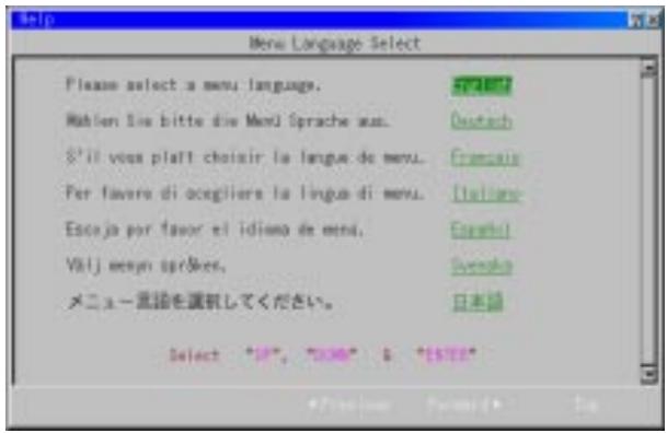
About Startup screen
(Menu Language Select screen)
When you first turn on the projector, you will get the Startup screen. This screen gives you the opportunity to select one of the seven menu languages: English, German, French, Itilan, Spanish, Swedish and Japanese.
To select a menu language, follow these steps:
- Use the Select ▲ or ▼ button to select one of the seven languages for the menu.
text_image
Menu Language Select Please select a menu language. Mahlen Sie bitte die Menji Sprache aus. S'il vous plaît choisir la langue de menu. Per favoro di ocegliere la lingua di menu. Escola por favor el idismo de menu. Välj mesen spr&es. メニュー言語を選択してください。 Select "IP", "BID" & "BID"- Press the Enter button to execute the selection.
- The Basic/Custom menu will be displayed in the language you have selected.
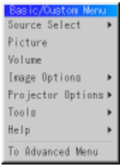
text_image
Basic/Custom Menu Source Select Picture Volume Image Options Projector Options Tools Help To Advanced MenuTo close the menu, press the Cancel button.
After this has been done, you can proceed to the advanced menu operation.
If you want, you can select the menu language later. See “Language” on page E-35.
3. OPERATION
This section describes how to select a computer or video source, how to adjust the picture, and how to customize the menu or projector settings.
General Controls
Before you turn on your projector, ensure that the computer or video source is turned on and that your lens cap is removed.
1. Turn on the Projector
Plug the supplied power cable in the wall outlet. The projector will go into its standby mode and the power indicator will glow orange.
Only after you press the “On” button on the remote control (“ON/STAND BY” button on the projector cabinet) will the power indicator turn to green and the projector become ready to use.
NOTE: To turn the projector on by plugging in the power cable, use the menu and enable the "Auto Start" feature. (See page E-37.)
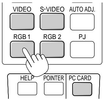
2. Select the Computer, Video Source or PC Card Viewer
Press a source button on the remote control or the projector cabinet to select “Video” (VCR, document camera, or laser disc player), S-Video”, “RGB 1 or 2” (computer or DVD with component output) or “PC Card Viewer” to display the image.
Or press the “Menu” button on the remote control or the cabinet and use the menu to select your video source: “Video”, “S-Video”, “RGB1 or 2”, or “PC Card Viewer”.
3. Adjust the Image Size and the Focus
Use the Zoom ring to adjust the image size, then use the Focus ring to obtain the best focus.
Use the “Magnify” button (+) or (-) on the remote control to make the image larger up to 400%.
4. Turning off the Projector
First press the “off” button on the remote control (“ON/STAND BY” button on the projector cabinet) for a minimum of two seconds. The power indicator will glow orange. Then, unplug the power cable. The power indicator will go out.
IMPORTANT:
- The projector should be unplugged if it will not to be used for an extended period.
- To turn off the image and sound briefly (five minutes or less), use the "Picture Mute" button instead of turning the projector off and on.
- The projector will display a black, blue image or logo if no input signal is present.
- Do not turn the projector off and then immediately back on. The projector needs to cool for a minute before it can be restarted.
After the projector turns off, the cooling fans keep operating for a full minute.
Do not disconnect the power cable during this time.
Using the Menus
NOTE: The on-screen menu may not be displayed correctly while interlaced motion video image is projected.
- Press the "Menu" button on the remote control or projector cabinet to display the Main Menu.
NOTE: When using a USB mouse, click the mouse button to display the main menu. For other operations, do the same way as you use your PC mouse.
-
Press the ▲▼ buttons on the remote control or the projector cabinet to highlight the menu for the item you want to adjust or set.
-
Press the ▶ button or the “Enter” button on the projector cabinet or the “Left Click” button on the remote control to select a submenu or item.
- Adjust the level or turn the selected item on or off by using "Select" ▶or▶ buttons on the cabinet, or the "Mouse button" on the remote control. The on-screen slide bar will show you the amount of increase or decrease.
- Changes are stored until you adjust it again.
ENTER ...... Stores the setting or adjustments.
CANCEL...... Return to the previous screen without storing settings or adjustments.
NOTE: You can close the main and sub menus simultaneously by pressing the PJ button to cancel the Projector mode.
- Repeat steps 2-5 to adjust an additional item, or press "Cancel" on the projector cabinet or the remote control to quit the menu display.
Using a USB Mouse
Using a USB mouse gives you a smooth operation. A commercially available USB mouse is required.
NOTE: There may be some brands of USB mouse that the projector does not support.
Operate the Menus using the USB mouse:
Mouse Cursor:
When connecting a USB mouse to the projector, you get a mouse cursor on the screen.
Unless you use your USB mouse within 10 seconds, the mouse cursor disappears.
Menu Display:
Clicking with a mouse button displays the main menu.
Clicking ▶ displays the pull-down menu.
To close the menu, click anywhere in the background.
Adjusting and Setting Display:
You can select a menu item and click with a mouse button to make adjustments and setting.
Examples:
Click (or press and hold) the mouse button ◀ or ▶ to adjust the brightness.
Or click and drag the mouse button on the slide bar horizontally to adjust it.
To save the adjustments, click ✗. The display is closed.
If you click anywhere in the background while displaying adjustment and setting menu or dialog box, you will get the main menu at the clicking point.
NOTE: The MOUSE OUTPUT port on the projector is not compatible with the USB mouse.
Basic Operation
Selecting the computer or video source:

flowchart
graph TD
    A["SOURCE"] --> B["○"]
    B --> C["AUTO ADJUST"]
Each time the Source button is pressed, the input source will change as follows:

If no input signal is present, the input will be skipped.
text_image
VIDEO S-VIDEO AUTO ADJ. RGB 1 RGB 2 PJ HELP POINTER PC CARD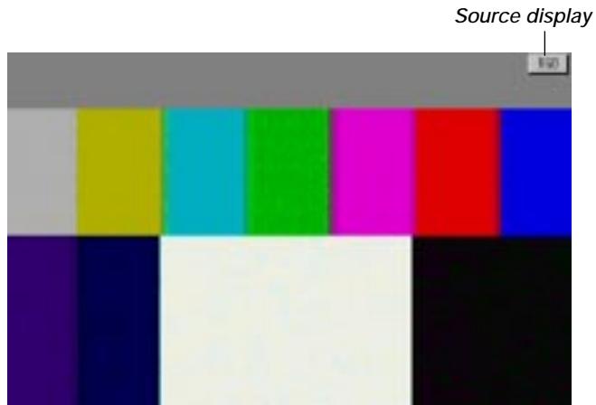
text_image
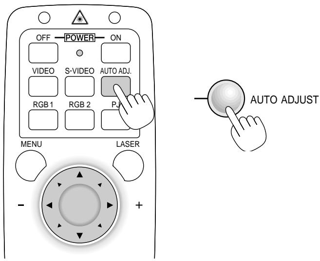
Source displayAdjust the Image Using Auto Adjust
The Auto Adjust function automatically optimizes the image in RGB mode.
text_image
OFF POWER ON VIDEO S-VIDEO AUTO ADJ. RGB 1 RGB 2 PJ MENU LASER AUTO ADJUST - +[Poor picture]
natural_image
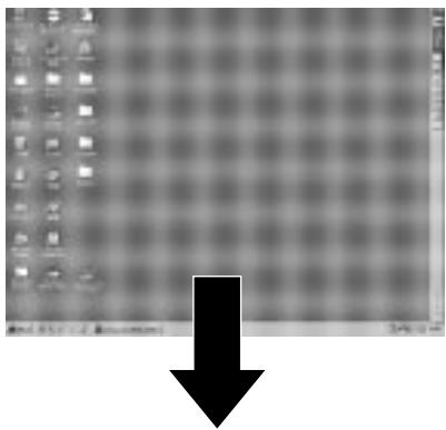
Computer desktop with a grid background and a large black downward arrow overlay (no readable text or symbols)[Normal picture]
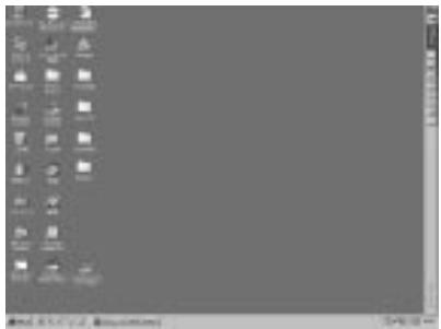
text_image
Scanned screenshot of a desktop computer interface with icons and system status bar at bottomPress the Auto Adjust button to fine-tune the computer image or to remove any vertical banding that might appear and to reduce video noise, dot interference or cross talk (this is evident when part of your image appears to be shimmering). This function adjusts the clock frequencies that eliminate the horizontal banding in the image. This function also adjusts the clock phase to reduce video noise, dot interference or cross talk. (This is evident when part of your image appears to be shimmering.)
This adjustment may be necessary when you connect your computer for the first time.
NOTE: The Auto Adjust function does not work for component signal.
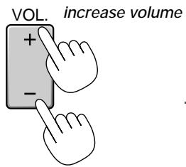
Volume control:
Sound level from the speaker on the projector can be adjusted.
text_image
VOL. increase volume + - -decrease volume
Turning off picture and sound:
Press the Picture Mute button to turn off the image and sound for a short period of time. Press again to restore the image and sound.

Getting Help about how to operate the projector:
You get the contents about Help.

text_image
HELP Display Help MENU LASER - + R-CLICK/CANCE Exit Help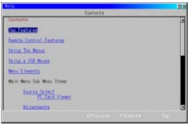
text_image
Help Contents Contents Up Features Remote Control Features Using The Menu Using a USB Mouse Menu Elements Main Menu Sub Menu Items Source Select PC Card Viewer AdjustmentsUsing Pointer
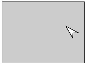
You can use one of eight pointers to draw your audience's attention to the portion of a projected image you want.
Press the Pointer button to display the pointer.
natural_image
Simple black arrow pointing diagonally upward on a gray background (no text or symbols)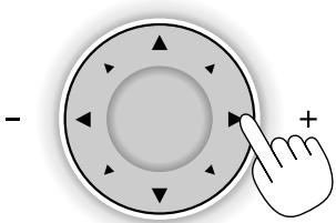
natural_image
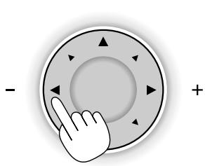
Hand pointing at a circular button with directional arrows (no text or symbols)Use the Select button to move the pointer.
natural_image
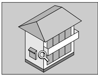
Simple gray rectangle with a white paper airplane icon in the top-right corner (no text or symbols)Enlarging and Moving a Picture
You can enlarge the area you want up to 400 percent.
To do so:
- Press the Pointer button to display the pointer.
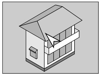
natural_image
Isometric illustration of a house with a roof and window (no text or symbols)- Move the pointer to the area you want to enlarge.
natural_image
Hand cursor clicking a circular button with directional arrows (no text or symbols)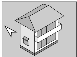
natural_image
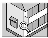
Isometric illustration of a house with a paper airplane pointing to its roof (no text or symbols)- Enlarge the selected area.
When the Magnify (+) button is pressed, the pointer is changed to a magnifying glass. To move the magnifying glass, use the Mouse button.

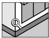
4. Return the image to the original size.
natural_image
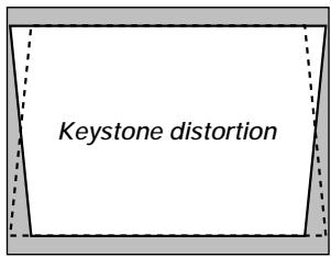
Isometric illustration of a house with a magnifying glass on the roof (no text or symbols)Correcting Keystone distortion
Press (+) or (-) to correct keystone (trapezoidal) distortion to make the top or bottom of the screen longer or shorter so that the projected image is rectangular.
text_image
Keystone distortion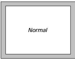
text_image
NormalNOTE: The maximum keystone angle that can be corrected is 40 degrees upward and 20 degrees downward with the projector placed horizontally on the ground plane.
Depending on the type of graphics being used, the picture may get blurred or keystone correction may not be possible when excessive keystone correction is used.
The idea is, the closer you are to native resolution, the better image you will see.
Freezing a picture
Press the Freeze button to freeze a picture. Press again to resume motion.

Customizing Basic/Custom Menu
The Basic/Custom menu can be customized to meet your requirements. Selecting a menu item from the “Basic/Custom Menu Edit” list, allows you to custom tailor the menu items to your needs.
- Select “Basic/Custom Menu Edit” to display the “Basic/Custom Menu Edit” screen.
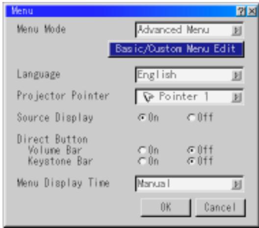
text_image
Menu Menu Mode Advanced Menu Basic/Custom Menu Edit Language English Projector Pointer Pointer 1 Source Display On Off Direct Button Volume Bar On Off Keystone Bar On Off Menu Display Time Manual OK Cancel- Use the ▲ or ▼ button to highlight your selection and press the Enter button to place a check mark next to an option. This action enables that feature.
Press the Enter button again to clear the check box.
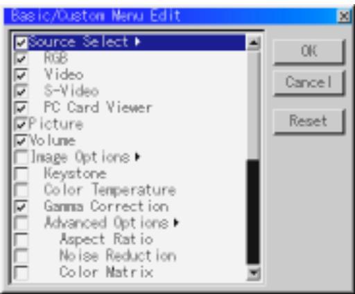
text_image
Basic/Custom Menu Edit Source Select ▶ RGB Video S-Video PC Card Viewer Picture Volume Image Options ▶ Keystone Color Temperature Gamma Correction Advanced Options ▶ Aspect Ratio Noise Reduction Color Matrix OK Cancel ResetIf you select an item with a solid triangle ▶ and press the Enter button on the remote control or the projector cabinet, you can enable all the items within that submenu.
Also you can turn on an item within the submenu without placing a check mark on the main menu item.
NOTE: Up to 12 main menu items (within Basic/Custom Menu Edit, not including submenu items) can be selected.
- In order for the changes to take effect, use the ◀ or ▶ button on the remote control or the projector cabinet to highlight “OK”, then press the Enter button. To cancel the changes, use the ▲ or ▼ buttons to highlight “Cancel” and press the “Enter” button. To return to the factory default, select “Reset” then press the “Enter” button.
The default Basic/Custom Menu items are:
Source Select (RGB1/2, Video, S-Video and PC Card Viewer), Picture, Volume, Image Options (Keystone, Color Temperature and Lamp Mode), Projector Options (Menu and Setup), Tools (Capture, PC Card Files and ChalkBoard) and Help (Contents and Information)
NOTE: Once you have selected OK on the Basic/Custom Menu Edit screen, you cannot cancel the changes on the Menu screen. However, you can re-edit the menu items over again as described in the steps above.
NOTE: If the “Advanced Menu” item has been selected on the Menu mode, you get the “Confirmation Change Menu” upon completion of “Basic/Custom Menu” editing. In this case, selecting “Yes” then “Enter” will close all the menus and apply the changes from the Advanced menu to the Basic/Custom Menu. If you select “No” then “Enter” functions, then all menu items will return to the Advanced menu, but your changes will still be available within the “Basic/Custom Menu” selection. To display the previously tailored Basic/Custom Menu, select “Basic/Custom Menu” from the “Menu Mode”.

text_image
Confirm Change Menu Change Basic/Custom menu now ? Yes NoAn item "To Advanced Menu" will be added to the bottom of the Basic/Custom Menu.
Selecting this item and pressing the "Enter" button will display the "Advanced Menu" features.
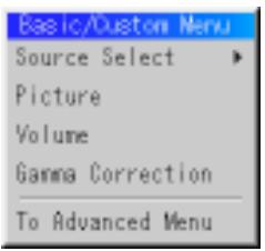
text_image
Basic/Dustom Menu Source Select Picture Volume Gamma Correction To Advanced MenuMenu Tree
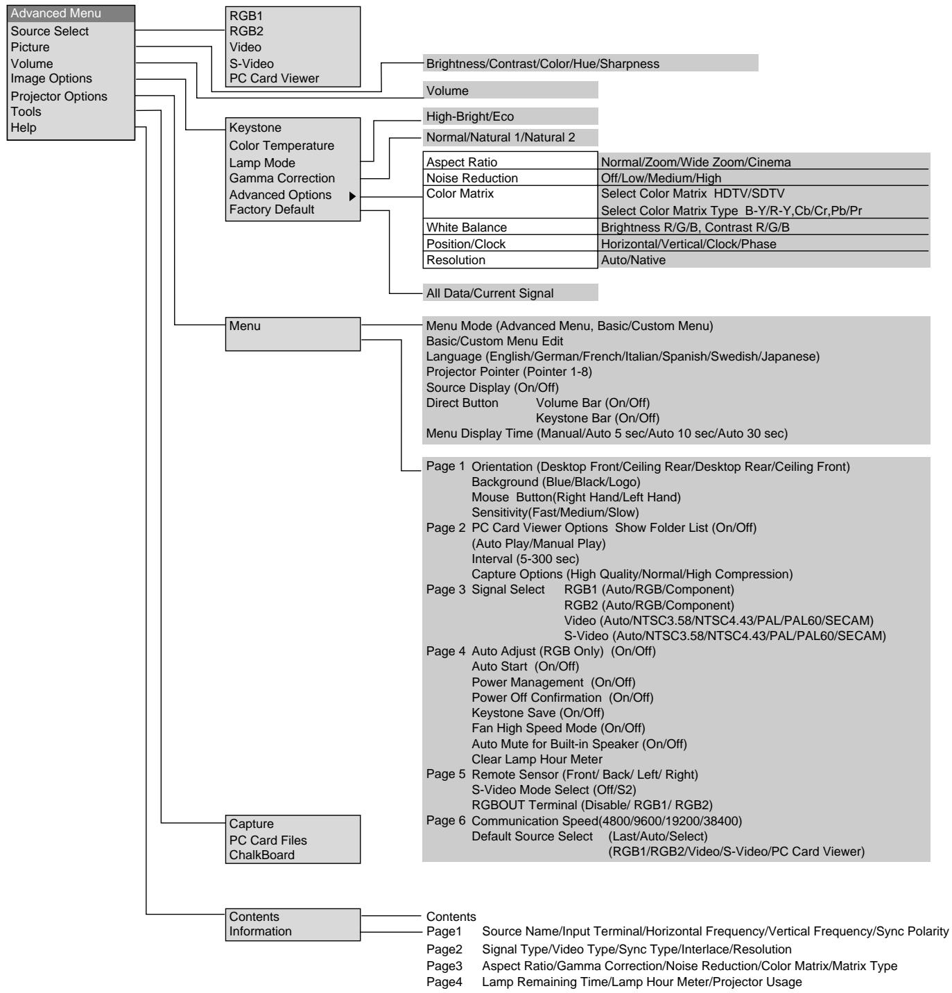
flowchart
graph TD
    A["Advanced Menu"] --> B["RGB1"]
    A --> C["RGB2"]
    A --> D["Video"]
    A --> E["S-Video"]
    A --> F["PC Card Viewer"]
    A --> G["Keystone Color Temperature Lamp Mode Gamma Correction Advanced Options Factory Default"]
    A --> H["Menu"]
    H --> I["Menu Mode (Advanced Menu, Basic/Custom Menu)"]
    H --> J["Basic/Custom Menu Edit Language (English/German/French/Italian/Spanish/Swedish/Japanese)"]
    H --> K["Projector Pointer (Pointer 1-8)"]
    H --> L["Source Display (On/Off)"]
    H --> M["Direct Button Volume Bar (On/Off)"]
    H --> N["Keystone Bar (On/Off)"]
    H --> O["Menu Display Time (Manual/Auto 5 sec/Auto 10 sec/Auto 30 sec)"]
    H --> P["Page 1 Orientation (Desktop Front/Ceiling Rear/Desktop Rear/Ceiling Front) Background (Blue/Black/Logo)"]
    H --> Q["Mouse Button(Right Hand/Left Hand) Sensitivity(Fast/Medium/Slow)"]
    H --> R["Page 2 PC Card Viewer Options Show Folder List (On/Off) (Auto Play/Manual Play)"]
    H --> S["Interval (5-300 sec) Capture Options (High Quality/Normal/High Compression)"]
    H --> T["Page 3 Signal Select RGB1 (Auto/RGB/Component)"]
    H --> U["RGB2 (Auto/RGB/Component)"]
    H --> V["Video (Auto/NTSC3.58/NTSC4.43/PAL/PAL60/SECAM)"]
    H --> W["S-Video (Auto/NTSC3.58/NTSC4.43/PAL/PAL60/SECAM)"]
    H --> X["Page 4 Auto Adjust (RGB Only) (On/Off) Auto Start (On/Off) Power Management (On/Off) Power Off Confirmation (On/Off) Keystone Save (On/Off) Fan High Speed Mode (On/Off) Auto Mute for Built-in Speaker (On/Off) Clear Lamp Hour Meter"]
    H --> Y["Page 5 Remote Sensor (Front/ Back/ Left/ Right) S-Video Mode Select (Off/S2) RGBOUT Terminal (Disable/ RGB1/ RGB2)"]
    H --> Z["Page 6 Communication Speed(4800/9600/19200/38400) Default Source Select (Last/Auto/Select) (RGB1/RGB2/Video/S-Video/PC Card Viewer)"]
    A --> AA["Capture PC Card Files ChalkBoard"]
    A --> AB["Contents Information"]

    B --> AC["Brightness/Contrast/Color/Hue/Sharpness"]
    B --> AD["Volume"]

    C --> AE["High-Bright/Eco"]
    C --> AF["Normal/Natural 1/Natural 2"]

    AD --> AG["Aspect Ratio Normal/Zoom/Wide Zoom/Cinema"]
    AD --> AH["Noise Reduction Off/Low/Medium/High"]
    AD --> AI["Color Matrix Select Color Matrix HDTV/SDTV Select Color Matrix Type B-Y/R-Y,Cb/Cr,Pb/Pr"]
    AD --> AJ["White Balance Brightness R/G/B, Contrast R/G/B"]
    AD --> AK["Position/Clock Horizontal/Vertical/Clock/Phase"]
    AD --> AL["Resolution Auto/Native"]

    AF --> AM["All Data/Current Signal"]

    H --> AN["Page 1 Orientation (Desktop Front/Ceiling Rear/Desktop Rear/Ceiling Front) Background (Blue/Black/Logo)"]
    H --> AO["Mouse Button(Right Hand/Left Hand) Sensitivity(Fast/Medium/Slow)"]

    AN --> AP["Page 2 PC Card Viewer Options Show Folder List (On/Off) (Auto Play/Manual Play)"]
    AN --> AQ["Interval (5-300 sec)"]

    AO --> AR["Page 3 Signal Select RGB1 (Auto/RGB/Component)"]
    AO --> AS["RGB2 (Auto/RGB/Component)"]

    AP --> AT["Page 4 Auto Adjust (RGB Only) (On/Off) Auto Start (On/Off)"]
    AP --> AU["Power Management (On/Off) Power Off Confirmation (On/Off)"]

    AQ --> AV["Page 5 Remote Sensor (Front/ Back/ Left/ Right) S-Video Mode Select (Off/S2)"]

    AR --> AW["Page 6 Communication Speed(4800/9600/19200/38400) Default Source Select (Last/Auto/Select) (RGB1/RGB2/Video/S-Video/PC Card Viewer)"]
Menu Elements
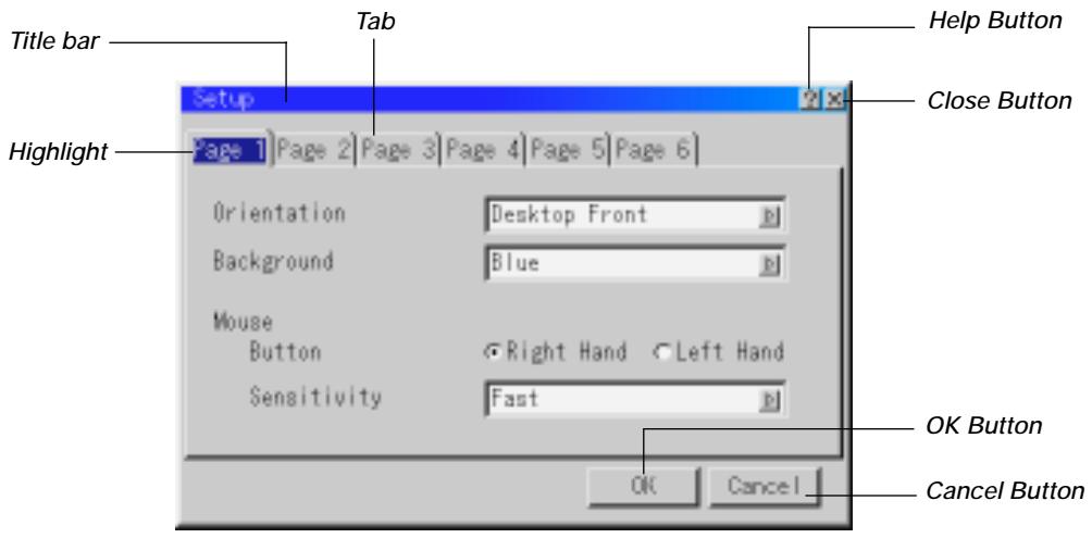
text_image
Title bar Tab Help Button Close Button Highlight Setup Page 1 Page 2 Page 3 Page 4 Page 5 Page 6 Orientation Desktop Front Background Blue Mouse Button Right Hand Left Hand Sensitivity Fast OK Cancel OK Button Cancel Button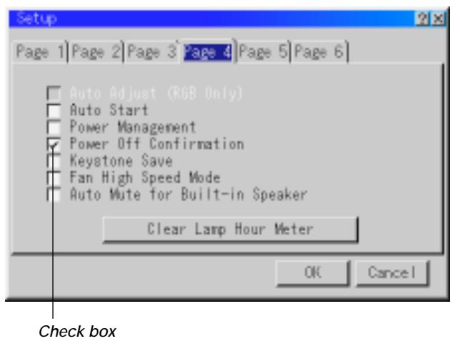
text_image
Setup Page 1 | Page 2 | Page 3 | Page 4 | Page 5 | Page 6 | Auto Adjust (RGB Only) Auto Start Power Management Power Off Confirmation Keystone Save Fan High Speed Mode Auto Mute for Built-in Speaker Clear Lamp Hour Meter OK Cancel Check box
text_image
Drag Tool bar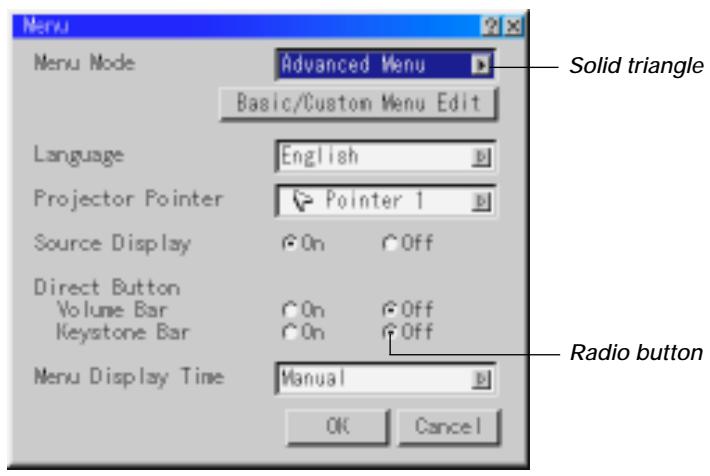
text_image
Menu Mode Advanced Menu Basic/Custom Menu Edit Language English Projector Pointer Pointer 1 Source Display On Off Direct Button Volume Bar On Off Keystone Bar On Off Menu Display Time Manual Radio button OK Cancel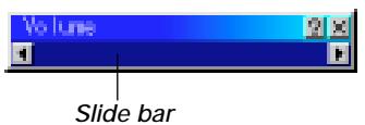
text_image
Volume Slide barMenu windows or dialog boxes typically have the following elements:
Title bar: Indicates the menu title.
Highlight: Indicates the selected menu or item.
Solid triangle: Indicates further choices are available. A highlighted triangle indicates the item is active.
Tab: Indicates a group of features in a dialog box. Selecting on any tab brings its page to the front.
Radio button: Use this round button to select an option in a dialog box.
Check box: Place a checkmark in the square box to turn the option On.
Slide bar: Indicates settings or the direction of adjustment.
OK button: Press to confirm your setting. You will return to the previous menu.
Cancel button: Press to cancel your setting. You will return to the previous menu.
Close button: Click to close the window with saving changes. (USB mouse only)
Help button: Indicates that help about that feature is available (USB mouse only). Press the Help button on the remote control to display help.
Toolbar: Contains several icons for specific tasks. It is also referred to as "launcher".
Drag: Point the mouse here, and click and drag to move a toolbar.
Menu Descriptions & Functions Source Select
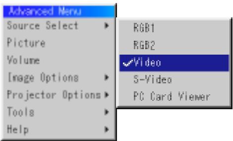
text_image
Advanced Menu Source Select ▶ RGB1 Picture Volume Image Options ▶ RGB2 Projector Options ▶ ✓Video Tools ▶ S-Video Help ▶ PC Card ViewerEnables you to select a video source such as a VCR, DVD player, laser disc player, computer or document camera depending on what is connected to your inputs.
Press the "Select" button on the projector cabinet or ▲▼ buttons on your remote control to highlight the menu for the item you want to adjust.
RGB1 / RGB2
Selects the computer connected to your RGB or component signal.
NOTE: An optional component cable (Component V cable) is needed for a component signal. Select "Component" from the Input Signal submenu to display the component signal.
Video
Selects what is connected to your Video input-VCR, laser disc player, DVD player or document camera.
S-Video
Selects what is connected to your S-Video input-VCR, DVD player, or laser disc player.
NOTE: A frame may freeze for a brief period of time when a video is played back in fast-forward or fast-rewind with a Video or S-Video source.
PC Card Viewer
This feature enables you to make presentations using a PC card that contains captured images and slides created with the exclusive PC Card Viewer Utility contained in the CD-ROM. See page E-41 for installing the PC Card Viewer Utility. The starting screen for the PC Card Viewer varies depending on the settings of the Setup's Page 2. See Setup on page E-36.
NOTE: Even if you switch the current PC Card Viewer source to another source, the current slide is retained. When you return back to the PC Card Viewer, you will get the slide that has been retained. A launcher will appear when you press the MENU button.

text_image
Advanced Menu Source Select Picture Volume Image Options Projector Options Tools Help RGB1 RGB2 Video S-Video ✓PC Card Viewer Prev Play Jump Setup View Drag Next Stop Select DeleteA press of the MENU button displays the toolbar; a press of the MENU button again displays the Menu and hereafter each press of the MENU button switches displaying between the Menu and the toolbar.
The launcher is a tool bar including the following buttons:
Drag ...... Drags to move the tool bar. (for USB mouse operation only)
Prev ...... Returns to the previous slide or folder.
Next ...... Advances to the next slide or folder.
Play ...... Plays back automatically or manually depending on the setting on PC Card Viewer Options of the menu. This allows you to move on to the next slide when "Manual Play" is selected.
Stop ...... Stops Auto Play while you are playing back and to resume playing from the selected slide or folder when "Auto Play" is selected.
Jump ...... Displays a list of slides while you are playing back.
Select ...... Displays a list of folders while you are playing back.
Setup ...... Displays the PC Card Viewer Options dialog box on Page 2 of the Setup dialog box.
Delete ...... Deletes a captured slide(s) or all the captured slides in the selected folder.
View ...... Hides the tool bar while you are playing back. Clicking with the right button of a mouse shows it again.
Picture (not available for PC Card Viewer)
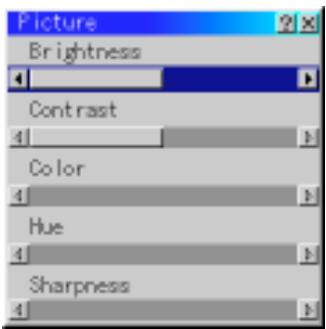
text_image
Picture Brightness Contrast Color Hue SharpnessProvides access to controls for your image. Use ▲▼ buttons on the projector cabinet or the remote control to highlight the menu for the item you want to adjust.
Brightness ... Adjusts the brightness level or the back raster intensity.
Contrast ...... Adjusts the intensity of the image according to the incoming signal.
Color ...... Increases or decreases the color saturation level (not valid for RGB).
Hue ...... Varies the color level from +/- green to +/-blue. The red level is used as reference. This adjustment is only valid for Video and Component inputs (not valid for RGB).
Sharpness .... Controls the detail of the image for Video (Not valid for RGB and Component).
Volume (not available for PC Card Viewer)

Adjusts the sound level of the projector.
NOTE: You can also display the volume bar without opening the menu. See "Volume Bar (Direct Button)" on page E-35 for more details.
Image Options
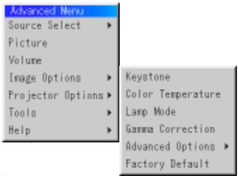
text_image
Advanced Menu Source Select ▶ Picture Volume Image Options ▶ Projector Options ▶ Tools ▶ Help ▶ Keystone Color Temperature Lamp Mode Gamma Correction Advanced Options ▶ Factory DefaultKeystone

This feature corrects the keystone (trapezoidal) distortion to make the top of the screen longer or shorter to be the same as the bottom. Use the ◀ or ▶ buttons on the slide bar to correct the keystone (trapezoidal) distortion.
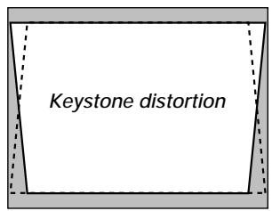
text_image
Keystone distortion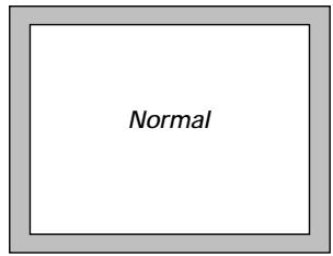
text_image
NormalNOTE: The maximum keystone angle that can be corrected is 40 degrees upward and 20 degrees downward with the projector placed horizontally on the ground plane.
Depending on the type of graphics being used, the picture may get blurred or keystone correction may not be possible when excessive keystone correction is used.
The idea is, the closer you are to native resolution, the better image you will see.
Color Temperature

This feature adjusts the color temperature using the slide bar. Move the slide bar to the right to increase the color temperature for a bluish image; to the left to decrease it for a reddish image.
Lamp Mode
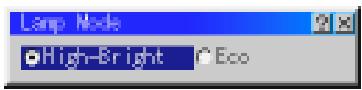
This feature enables you to select two brightness mode of the lamp: High-Bright and Eco modes. The lamp life can be extended up to 2500 hours by using the Eco mode.
High-Bright Mode ....This is the default setting. Eco Mode ....Select this mode to increase the lamp life.
NOTE: If you have selected the Eco mode, the lamp lights in High-Bright mode for 3 minutes after the projector is turned on. After 3 minutes the lamp will change to Eco mode.
Gamma Correction

text_image
Gamma Correct Normal Natural 1 Natural 2Use the ◀ or ▶ button to choose "Normal" when in a lighted room and "Natural 1&2" when in a darkened room. "Natural 1" for better flesh tone; "Natural 2" for true reproduction of middle tones. Each mode is recommended for :
Normal ...... For the regular picture
Natural 1 ..... For true color reproduction of natural tones
Natural 2 ..... For dark portions of a picture
Aspect Ratio (not available for RGB and PC Card Viewer)
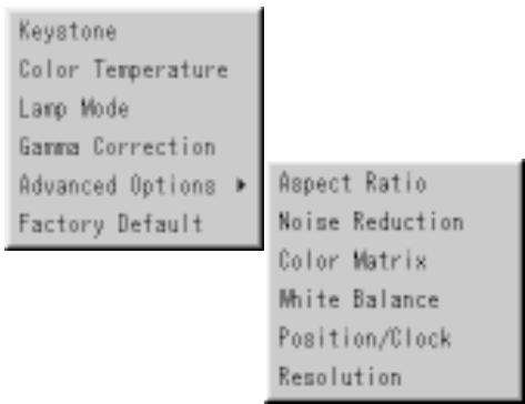
text_image
Keystone Color Temperature Lamp Mode Gamma Correction Advanced Options ▶ Factory Default Aspect Ratio Noise Reduction Color Matrix White Balance Position/Clock Resolution
text_image
Aspect Ratio Normal Zoom Wide Zoom CinemaAspect Ratio allows you to select the best Aspect mode to display your source image.
When 4:3 is selected from the source (i.e. DVD player), the following selections will display:
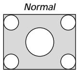
Standard
4:3 Aspect
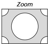
All 4 sides
stretched
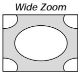
Left & Right
stretched
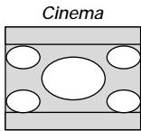
Left and right
stretched
When 16:9 is selected from the source (i.e. DVD player), the following selections will display:
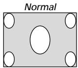
16:9 image displayed in 4:3 mode
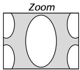
All 4 sides
stretched
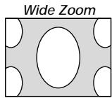
Left & right
stretched
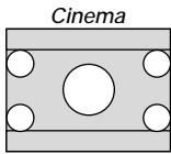
Left and right
stretched to
display the true
aspect
Noise Reduction (not available for RGB and PC Card Viewer)

text_image
Noise Reduction Off Low Medium HighYou can select three levels video noise reduction.
NOTE: The lower the Noise Reduction level, the better the image quality by way of higher video bandwidth.
Color Matrix (available for component video signal only)
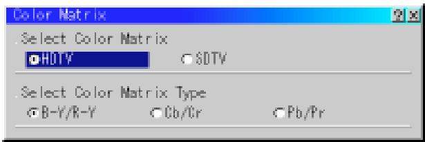
text_image
.Select Color Matrix ●HOTY ○SDTV . Select Color Matrix Type ○B-Y/R-Y ○Cb/Cr ○Pb/PrFirst select an appropriate color matrix to fit your component signal for HDTV or SDTV. Then select an appropriate matrix type from B-Y/R-Y, Cb/Cr or Pb/Pr.
White Balance
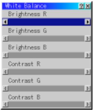
text_image
White Balance Brightness R Brightness G 4 Brightness B 4 Contrast R 4 Contrast G 4 Contrast B 4This allows you to adjust the white balance. Brightness for each color (RGB) is used to adjust the black level of the screen;
Contrast for each color (RGB) to adjust the white level of the screen.
First use the ▲ or ▼ buttons to select R, G, or B for the brightness and the contrast. Next use the ◀ or ▶ buttons to adjust the level.
Position/ Clock (when Auto Adjust is off)
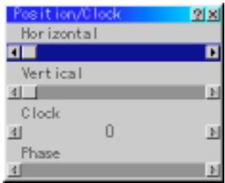
text_image
Position/Clock Horizontal Vertical Clock 0 PhaseThis allows you to manually adjust the image horizontally and vertically, and adjust Clock and Phase.
Horizontal/Vertical Position
.... Adjusts the image location horizontally and vertically using the ◀ and ▶ buttons.
This adjustment is made automatically when the Auto Adjust is turned on.
Clock...... Use this item to fine tune the computer image or to remove any vertical banding that might appear. This function adjusts the clock frequencies that eliminate the horizontal banding in the image.
Press the ◀ and ▶ buttons until the banding disappears.
This adjustment may be necessary when you connect your computer for the first time. This adjustment is made automatically when the Auto Adjust is turned on.
Phase ...... Use this item to adjust the clock phase or to reduce video noise, dot interference or cross talk. (This is evident when part of your image appears to be shimmering.) Use the ◀ and ▶ buttons to adjust the image.
See "Auto Adjust (RGB Only) on page E-37 for turning on or off the Auto Adjust feature.
Use "Phase" only after the "Clock" is complete.
This adjustment is made automatically when the Auto Adjust is turned on.
Resolution (when Auto Adjust is off)
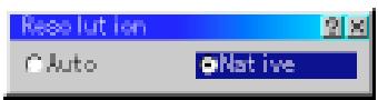
This allows you to activate or deactivate the Advanced AccuBlend feature.
Auto ...... Turns on the Advanced AccuBlend feature. The projector automatically reduces or enlarges the current image to fit the full screen.
Native ...... Turns off the Advanced AccuBlend feature. The projector displays the current image in its true resolution.
See "Auto Adjust (RGB Only) on page E-37 for turning on or off the Auto Adjust feature.
NOTE: While you are displaying an image with higher resolution than the projector's native resolution, even when you are in the Native mode, the image is displayed full screen using the Advanced AccuBlend feature.
Factory Default
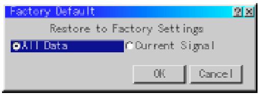
text_image
Factory Default Restore to Factory Settings All Data Current Signal OK CancelChanges all adjustments and setting to the factory preset for each source individually except Lamp Hour Meter, Projector Usage, Language and Communication Speed. (To reset the lamp usage time, see "Clear Lamp Hour Meter" on page E-37.)
All Data ...... Reset all the adjustments and settings for all the signals to the factory preset.
Current Signal ..... Resets the adjustments for the current signal to the factory preset levels.
The items that can be reset for the currently projected image are: Picture (Brightness, Contrast, Color, Hue and Sharpness) and Image Options (Color Temperature, Gamma Correction, Advanced Options [Aspect Ratio, Noise Reduction, Color Matrix, White Balance, Position/Clock and Resolution]).
NOTE: The Volume, Keystone, Lamp Mode and all the items in the Projector Options can be reset only when "All Data" is selected.
Projector Options
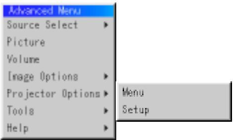
text_image
Advanced Menu Source Select Picture Volume Image Options Projector Options Tools Help Menu SetupMenu
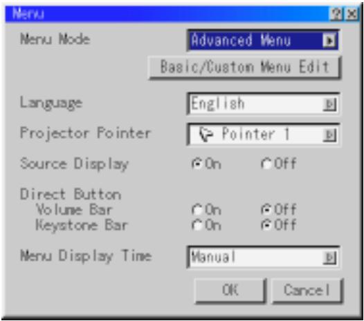
text_image
Menu Menu Mode Advanced Menu Basic/Custom Menu Edit Language English Projector Pointer Pointer 1 Source Display On Off Direct Button Volume Bar On Off Keystone Bar On Off Menu Display Time Manual OK CancelAllows you to set preferences for the on-screen menu. Press "OK" to save your changes for all the features.
Menu Mode:
This feature allows you to select two menu modes: Advanced Menu and Basic/Custom Menu.
Advanced Menu ...... This is the menu that contains all the available menus and commands.
Basic/Custom Menu .... This is the menu that you can customize using the Basic/Custom Menu Edit to fit your needs.
The factory default Basic/Custom menu includes:
Source Select (RGB1/2, Video, S-Video and PC Card Viewer), Picture, Volume, Image Options (Keystone, Color Temperature and Lamp Mode), Projector Options (Menu and Setup), Tools (Capture, PC Card Files and ChalkBoad) and Help (Contents and Information). See page E-28 for instructions about how to customize the Basic/Custom Menu.
Language:
You can choose one of seven languages for on-screen instructions. The options are: English, German, French, Italian, Spanish, Swedish and Japanese.
Projector Pointer:
This enables you to select from eight different Pointer icons for the "Pointer" button on your remote control.
After moving your Pointer icon to the area you want on the screen, press the Magnify button on the remote control to enlarge the selected area on the screen. See page E-27 for more details.

NOTE: There may be cases where the Pointer function is not available (ex. a non-interlace signal at 15kHz such as video game.)
Source Display:
You can turn on and off the information for input name such as VIDEO and RGB.
When this option is on, the current input will be displayed each time you switch sources or turn on the projector.
Direct Button:
Volume Bar: This option turns on or off the volume bar when you adjust the sound volume using VOL+/- button on the remote control.
On .... You can increase or decrease the sound volume with the volume bar on screen.
Off .... You can increase or decrease the sound volume without having to use the volume bar.
Keystone Bar: This option turns on or off the keystone bar when you adjust the keystone using KEYSTONE +/- button on the remote control.
On .... You can increase or decrease the level with the keystone bar on screen.
Off .... You can increase or decrease the level without having to use the keystone bar.
Menu Display Time :
This option allows you to select how long the projector waits after the last touch of a button to turn off the menu.
The preset choices are "Manual", "Auto 5 sec", "Auto 10 sec", and "Auto 30 sec". The "Auto 10 sec" is the factory preset.
Manual ...... The menu can be turned off manually.
Auto 5 sec .... The menu will automatically be turned off in 5 seconds if no buttons are pressed within 5 seconds.
Auto 10 sec .. The menu will automatically be turned off in 10 seconds if no buttons are pressed within 10 seconds.
Auto 30 sec .. The menu will automatically be turned off in 30 seconds if no buttons are pressed within 30 seconds.
NOTE: If no buttons on the remote control are pressed within 10 seconds, the PJ button's light goes out to indicate that you are in the Computer mode. To enable the projector menu operation again, press the PJ button again to light red.
Setup
Enables you to set operating options.
Press "OK" to save your changes for all the features of Page1, Page2,
Page3, Page 4, Page5 and Page6.
[Page1]
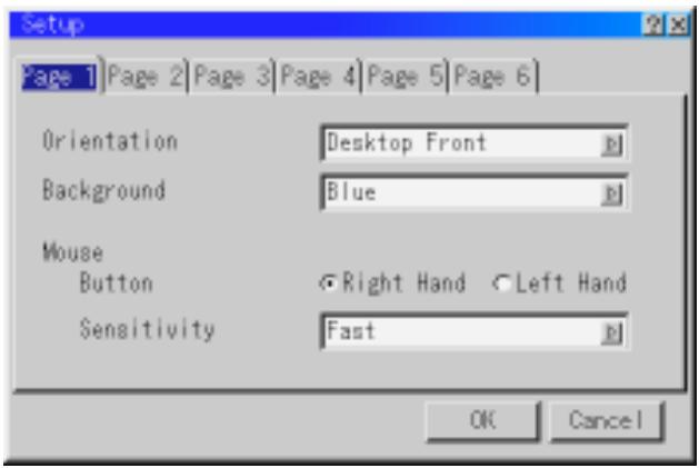
text_image
Setup Page 1 | Page 2 | Page 3 | Page 4 | Page 5 | Page 6 | Orientation Desktop Front Background Blue Mouse Button Right Hand Left Hand Sensitivity Fast OK CancelOrientation:
This reorients your image for your type of projection.
The options are: desktop front projection, ceiling rear projection, desktop rear projection, and ceiling front projection.
Background:
Use this feature to display a blue/ black screen or logo when no signal is available. The default background is blue. You can change the logo screen using the PC Card Files feature. See page E-39.
Mouse Settings:
This option lets you to change your USB mouse settings. The mouse settings feature is available for USB mouse only. Choose the settings you want:
Mouse Button ...... "Right Hand" or "Left Hand"
Mouse Sensitivity ..... "Fast", "Medium" or "Slow"
[Page2] PC Card Viewer Options
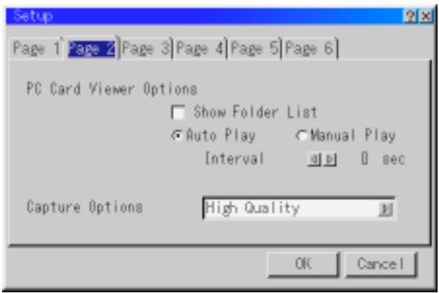
text_image
Setup Page 1 Page 2 Page 3 Page 4 Page 5 Page 6 PC Card Viewer Options Show Folder List Auto Play Manual Play Interval 0 sec Capture Options High Quality OK CancelShow Folder List:
If this option is checked, when PC Card Viewer input is selected on the projector, the folder lists will be displayed and allows you to select the presentation from a PC card.
Auto Play:
If this option is checked, any given slide will start to play automatically.
Auto Play Interval:
You can specify interval time between 5 and 300 seconds.
NOTE: The Auto Play Interval time set on the PC Card Viewer Utility overrides the one set here.
Manual Play:
Views a slide manually when PC Card Viewer input is selected.
NOTE: The Auto Play and Manual Play options determine the behavior of the Play/Stop [ ] icon on the Viewer toolbar.
NOTE: If you check "Auto Play" and select "PC Card Viewer" on the projector, the slides will automatically start to play back from any given slide.
Capture Options: (available for JPEG only)
These options are used for the Capture function that you can select from Tools. You have three options for JPEG compression quality: High quality, Normal and High Compression.
High Quality. Gives quality of JPEG a priority.
Normal ...... Gives normal JPEG quality.
High Compression Gives compression a priority.
[Page3] Signal Select

text_image
Setup Page 1 Page 2 Page 3 Page 4 Page 5 Page 6 Signal Select RGB1 Auto RGB2 Auto Video Auto S-Video Auto OK CancelRGB1/2:
Allows you to choose "RGB" for an RGB source such as a computer, or "Component" for a component video source such as a DVD player. Normally select "Auto" and the projector automatically detects a component signal. However there may be some component signals that the projector is unable to detect. If this is the case, select "Component".
VIDEO and S-VIDEO:
This feature enables you to select composite video standards manually. Normally select "Auto".
Select the video standard from the pull-down menu.
This must be done for Video and S-Video separately.
[Page4]

text_image
Setup Page 1 Page 2 Page 3 Page 4 Page 5 Page 6 Auto Adjust (RGB Only) Auto Start Power Management Power Off Confirmation Keystone Save Fan High Speed Mode Auto Mute for Built-in Speaker Clear Lamp Hour Meter OK CancelAuto Adjust (RGB Only):
When "Auto Adjust" is set to "On", the projector automatically determines the best resolution for the current RGB input signal to project an image using NEC's Advanced AccuBlend Intelligent Pixel Blending Technology.
The image can be automatically adjusted for position and stability; "Horizontal Position", "Vertical Position", "Clock", "Phase", and "Resolution."
On ...... Automatically adjusts image "Horizontal Position", "Vertical Position", "Clock", "Phase" and "Resolution".
Off ...... User can adjust the image display functions ("Horizontal Position", "Vertical Position", "Clock", "Phase" and "Resolution") manually.
Auto Start:
Turns the projector on automatically when the power cable is inserted into an active power outlet. This eliminates the need to always use the "Power" button on the remote control or projector cabinet.
Power Management:
When this option is on and there is no RGB input for five minutes or more, the projector will automatically turn itself off.
Power Off Confirmation:
This option determines whether a confirmation dialog for turning off the projector will appear or not.
NOTE: When the confirmation message is displayed, you must be in the Projector mode to operate your projector using the remote control. If not, press the PJ button on the remote control to change your projector to the Projector mode. The button lights to indicate that you are in the Projector mode.
Keystone Save:
This option enables you to save your current keystone settings. Saving your change once affects all sources. The changes are saved when you turn off the projector.
Fan High Speed Mode:
This option allows you to select two modes for fan speed: high-speed mode and normal speed mode.
When you wish to cool down the temperature inside the projector quickly, check this box. This is convenient especially when the projector is installed on the ceiling.
Auto Mute for Built-in Speaker:
This option allows you to mute the built-in speakers automatically when you connect an audio cable to the AUDIO OUT terminal.
Clear Lamp Hour Meter:
Resets the lamp clock back to zero. Pressing this button appears a confirmation dialog box. To reset the lamp usage hour, press "OK".
NOTE: The projector will turn off and go into standby mode after 1600 hours (up to 2600 hours in Eco mode) of service. If this happens, press the "Help" button on the remote control for ten seconds to reset the lamp clock back to zero. Do this only after replacing the lamp.
[Page5]
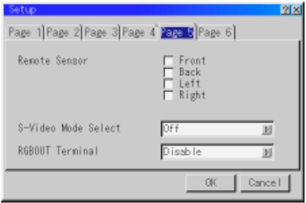
text_image
Setup Page 1 Page 2 Page 3 Page 4 page 5 Page 6 Remote Sensor Front Back Left Right S-Video Mode Select Off RGBOUT Terminal Disable OK CancelRemote Sensor:
This option determines which remote sensors on the projector are enabled in wireless mode.
The options are: front, rear, right, or left. All checked boxes indicate that they can accept the infrared signal from the supplied remote control.
S-Video Mode Select:
This feature is used to select the S-Video signal detection mode. This allows identifying of the S-Video signals with different aspect ratio (Zoom signal 16:9, Wide Zoom signal 4:3).
S2 ...... Identifies Zoom or Wide Zoom signal.
OFF ...... Does not identify any S-video signal.
RGBOUT Terminal:
This option allows you to determine which RGB source is output from the RGBOUT terminal when the Video, S-Video or Viewer source is selected.
Disable ...... Neither RGB 1 nor RGB 2 is output from the RGBOUT terminal.
RGB 1 ...... The signal from RGB 1 is output from the RGBOUT terminal.
RGB 2 ...... The signal from RGB 2 is output from the RGBOUT terminal.
NOTE: The AUDIO OUT mini jack outputs sound for the source that the projector currently selects independently of setting "RGB OUT Terminal".
[Page6]
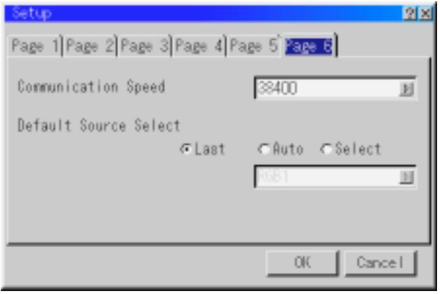
text_image
Setup Page 1 | Page 2 | Page 3 | Page 4 | Page 5 | Page 6 | Communication Speed ≥400 Default Source Select Last Auto Select OK CancelCommunication Speed:
This feature sets the baud rate of the PC Control port (Mini DIN 8 Pin).
It supports data rates from 4800 to 38400 bps.
The default is 38400 bps. Select the appropriate baud rate for your equipment to be connected.
Default Source Select:
You can set the projector to default to any one of its inputs each time the projector is turned on.
Last...... Sets the projector to default to the previous or last active input each time the projector is turned on.
Auto ...... Searches for an active source in order of RGB1 → RGB2 → Video → S-Video → PC Card Viewer → RGB1 and displays the first found source.
Select ...... Displays the selected source input every time the projector is started up. Select an input from the pull-down menu.
Tools
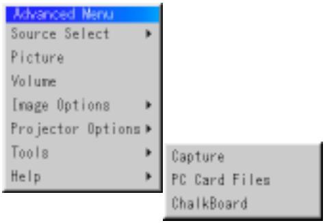
text_image
Advanced Menu Source Select Picture Volume Image Options Projector Options Tools Help Capture PC Card Files ChalkBoardProvides tools for capturing images, displaying files in a PC Card and drawing.
NOTE: The "Capture" and "PC Card Files" features are required for a PC card.
Capture:
Allows you to capture an image from a source that is currently being displayed. The image is saved as JPEG in the PC card.
When you select Capture from the menu, you will get a tool bar. You can capture an image directly using the tool bar when the menu is not displayed.
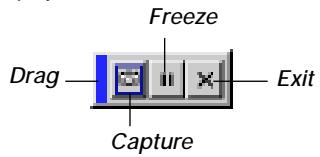
text_image
Freeze Drag ———— Capture ———— ExitThe tool bar includes the following buttons:
Drag ...... Drags to move the tool bar. (for USB mouse operation only)
Capture ...... Captures an image and save it as a JPEG file in a PC card.
Freeze ...... Freezes and unfreezes images.
Exit ...... Exits the Capture function.
Unless a PC card is inserted into the PC Card slot of the projector, the Capture feature is not available.
The "Card Error" display means that the free space of the PC card is insufficient for saving images. Make more space available on the card by erasing unwanted images with your PC. The number of images that can be captured depends on the size of the PC card.
NOTE: Be sure not to turn off the power or remove the PC card while capturing an image. Doing so could cause a loss of the data in the PC card or damage to the card itself.
NOTE: Captured images with higher resolution than the projector's native resolution cannot be displayed correctly.
PC Card Files:
Displays a list of all the files stored in the PC card so that you can select a file you want to display. You can also sort files by file name or date, or display the file.
Although a list of all the files in the PC card is displayed, you can view files in idx, text, HTML, JPEG and BMP format only.
Selecting BMP and JPEG files automatically switches to the PC Card Viewer source.
NOTE: When an image with a resolution of XGA (1024×768) or higher is projected, the PC Card Files screen may not be correctly displayed.
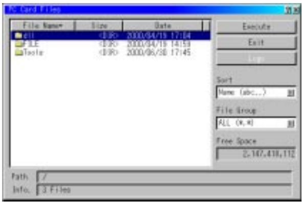
text_image
PC Card Files File Name Size Date dll <0:0> 2000/04/19 17:04 FILE <0:0> 2000/04/19 14:53 Tools <0:0> 2000/06/30 17:45 Execute Exit Sort Name (abc...) File Group ALL (x,) Free Space 2.147.418.112 Path: / Info: 3 FilesSelecting "Execute" displays the file you selected.
When you select a JPEG or BMP file and press the Enter button on the remote or the cabinet, or "Execute" on the above, you will get a toolbar. This toolbar is used to return to the PC Card Files screen.
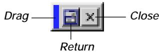
Drag ...... Drags to move the tool bar. (for USB mouse operation only)
Return ...... Returns to the PC Card Files screen.
Close ...... Close the toolbar.
Changing Background Logo:
The Logo button allows you to select a background logo from graphic files on a PC card and change to it as the background logo.
NOTE: File size must be 64KB or less. Other file formats than JPEG and BMP are not available.
- Use the ▲ or ▼ button to select a JPEG or BMP file for your background logo.
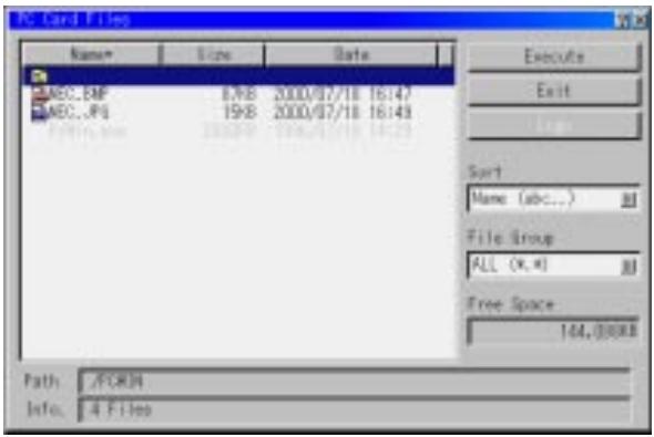
text_image
PC Grid Files Name Size Data ACC_EMP 89KB 2000/07/18 16:47 MEC_JP 19KB 2000/07/18 16:43 Sort Name (abc...) File Group ALL (x, x) Free Space 144,300KB Path : /FORM Info: 4 Files-
Use the ▶ and then ▼ button to select "Logo".
-
Press the Enter on the remote control or the cabinet. You will get the confirmation dialog box.

text_image
Change Logo Data ? OK Cancel- Select "OK" and press the Enter button. This completes changing a logo for the background.
* Once you have changed the background from the NEC logo to another, you cannot return the logo to background even by using Factory Default. To do so, repeat the above steps. The NEC logo file is included on the supplied CD-ROM (/logo/nec_b_x.jpg).
ChalkBoard: (available only when using with USB mouse) Provides the tool bar for producing freehand drawings.
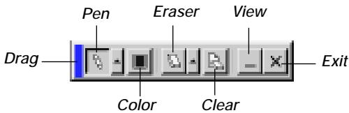
text_image
Pen Eraser View Drag Color Clear ExitDrag ...... Drags to move the tool bar. (for USB mouse operation only)
Pen ...... Left-click and drag to draw. Left-click [▲] or right-click the pen icon to display the pen palette containing four lines of different thickness from which you can select a line you prefer by left-clicking.
Color ...... Selects a color. Left-click to display the color palette from which you can select a color you prefer by left-clicking.
Eraser ...... Left-click and drag to erase part of a drawing. Left-click [▲] or right-click the eraser icon to display the eraser palette containing four eraser of different thickness from which you can select an eraser you prefer by left-clicking.
Clear ...... Left-click to clear the drawing completely from the ChalkBoard screen.
View ...... Hides the tool bar by left-clicking. Right-clicking anywhere on the screen displays the ChalkBoard tool bar again.
Exit ...... Clears the complete drawing and exits the ChalkBoard.
NOTE:
* The ChalkBoard feature is available only when a USB mouse is used. Free-hand drawings cannot be saved or captured.
* The menu is not available while you display the ChalkBoard screen.
* The Capture function is not available on ChalkBoard screen.
* Switching slides clears a drawing completely.
Help
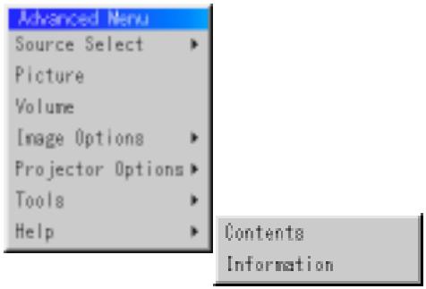
text_image
Advanced Menu Source Select Picture Volume Image Options Projector Options Tools Help Contents InformationContents:
Provides an online help about how to use the menus. An underlined link means that you can move to an adjustment item directly. Selecting the underlined link and pressing ENTER moves to the corresponding adjustment item.
NOTE: The Help Menu may not be displayed correctly when a UXGA signal is displayed.
Information:
Displays the status of the current signal, and the lamp and the projector usage hours.
This dialog box has four pages.
The information included are as follows:
| [Page 1] | [Page 2] |
| Source Name | Signal Type |
| Input Terminal | Video Type |
| Horizontal Frequency | Sync Type |
| Vertical Frequency | Interlace |
| Sync Polarity | Resolution |
| [Page 3] | [Page 4] |
| Aspect Ratio | Lamp Remaining Time (%) |
| Gamma Correction | Lamp Hour Meter (H) |
| Noise Reduction | Projector Usage (H) |
| Color Matrix | |
| Matrix Type |
NOTE: The progress indicator shows the percentage of remaining bulb life. The value informs you of the amount of lamp and projector usage respectively.
Using the PC Card Viewer function
NOTE: When using the supplied software (CD-ROM)
The software is designed to use with a personal computer only. Do not play the software on CD player. Doing so could cause damage to speakers.
Features
The Viewer feature allows slides stored on a PC memory card (referred to as PC card in this manual) to be displayed on the projector. Even if no computer is available, presentations can be conducted simply with the projector. This feature is convenient for holding presentations at meetings and in offices, as well as for playing images taken on digital cameras.
Easy to use
- Presentations can be started immediately simply by inserting a PC card (not supplied)
- Easy slide switching
- Remote control operation
- Jumping to list of slides or any specific slide
High quality images
• High resolution up to 1024×768 dots(MT850: up to 800×600 dots)
• 24-bit full color playback
• Viewing of digital camera images
Simple utility software (for computer)
• PC Card Viewer Utility operable on Windows 95/98/NT4.0/2000
- Slides can be created by capturing the currently displayed image
• Control screen for displaying lists of slides and editing
- PC Card Viewer PPT Converter 1.0 [Add-In Version] converts files created with Microsoft PowerPoint 95/97/2000 (hereafter referred to as PowerPoint) into indexes playable with PC Card Viewer
* Microsoft, Windows and PowerPoint are registered trademarks of Microsoft Corporation.
Inserting and Ejecting a PC Card
A PC card is used to view presentation data prepared on the computer and to capture and play images projected with the projector.
Inserting the PC Card
- Hold the PC card horizontally and insert it slowly into the card slot with its top facing up.
- The eject button pops out once the PC card is fully inserted. Check that the PC card is fully inserted.
NOTE: Do not try to force the PC card into the slot.
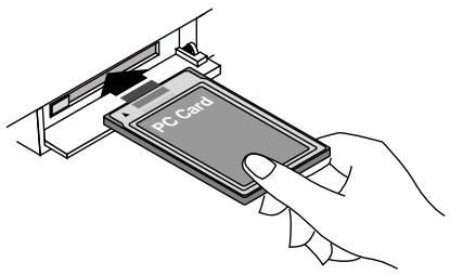
text_image
PC CardEjecting the PC Card
Press the eject button. The PC card pops out a little. Grasp the edges of the PC card and pull it out. Do not eject the PC card while its data is being accessed.
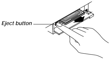
text_image
Eject buttonDirection for Inserting the PC Card
The PC card has a top and bottom and must be inserted into the PC card slot in a specific direction. It cannot be inserted backwards or upside-down. Attempting to force it into the slot in the wrong direction may break the internal pin and damage the card slot. Refer to the PC card's operating instructions for the proper direction of insertion.
PC Card Type
The PC Card slot accepts PCMCIA Type II only.
Installing the PC Card Viewer Software
Before Installing
Perform the following before installing the PC Card Viewer software:
- If Windows is already started, exit all applications. Installation may not be performed properly if any applications are running.
Installation
Install the viewer software as described below.
To quit installation before it is completed, press the "Cancel" button then follow the instructions in the dialog box.
- Start up Windows.
- Insert the CD-ROM into the CD-ROM drive.
The auto CD play function automatically starts the CD-ROM's program and the contents screen appears.
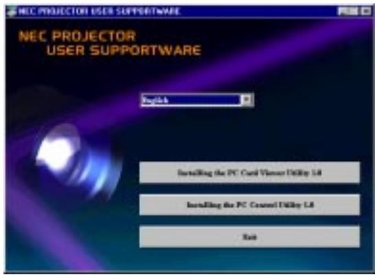
text_image
NEC PROJECTOR USER SUPPORTWARE English Installing the PC Control Utility L8 Installing the PC Control Utility L8 Exit* The auto CD play function operates if the "Auto insert notification" box in the computer's CD-ROM control panel is checked. (The box is checked by default.)
- Click [Installing the PC Card Viewer Utility 1.0] The setup dialog appears.
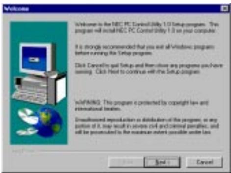
text_image
Welcome Welcome to the HEC PC Control Utility 1.0 Setup program. This program will install HEC PC Control Utility 1.0 on your computer. It is strongly recommended that you exit all Windows programs before running the Setup program. Click Cancel to get Setup and then close any programs you have seen. Click Next to continue with the Setup program. WINPARING: This program is protected by copyright law and international legal. Discontinued reproduction as distribution of the program, as any portion of it may result in various civil and criminal penalties, and will be prevented to ensure extent possible under law.* Follow the instructions in the setup dialog to complete the installation.
For instructions on uninstalling the PC Card Viewer software, see page E-45.
Starting Up the PC Card Viewer Software on your PC
(PC Card Viewer Utility 1.0)
Use the PC Card Viewer Utility 1.0 for creating viewer slides.
To start the PC Card Viewer software:
* Select [Start]-[Programs]-[NEC Projector Tools]-[PC Card Viewer Utility 1.0].
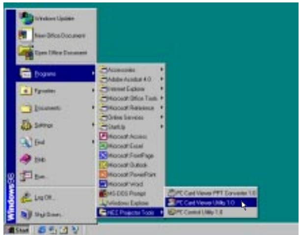
text_image
Windows 3.6 Start New Office Documents Open Office Documents Programs Keywords Documents Solver Eval Edit Run... Log Off... High Sizes Accessories Adobe Acrobat 4.0 Internet Explorer Microsoft Office Tools Microsoft Reference Online Services Startup Microsoft Access Microsoft Excel Microsoft PowerPoint Microsoft Outlook Microsoft PowerPoint Microsoft Word MS-DOS Prompt Windows Express HES Projector Tools PC Card Venue PRT Converter 1.0 PC Card Venue Utility 1.0 PC Control Utility 1.0Refer to online help for instructions on using the PC Card Viewer software.
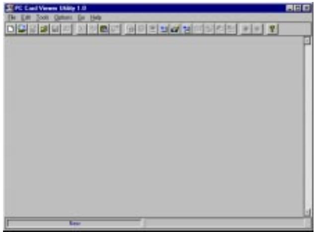
text_image
PC Cart Version Utility 1.0 File Edit Tools Options Get HelpContents of the English version PC Card Viewer software (PC Card Viewer Utility 1.0)
This is the software used for creating PC Card Viewer slides. In this manual it is referred to as the "PC Card Viewer software".
PC Card Viewer PPT Converter 1.0
This is an application that converts files created with Microsoft PowerPoint 95/97/2000 into indexes so that they can be played directly with the PC Card Viewer Utility 1.0.
PC Card Viewer PPT Converter is installed automatically when you install the PC Card Viewer Utility.
To start PC Card Viewer PPT Converter:
* Select PC Card Viewer PPT Converter from NEC Projector Tools.
Basic Operation of the PC Card Viewer Software
PC Card Viewer Utility is an application for editing documents, converting them into slides and storing them on PC cards as playback data (indexes) for presentations using projectors.
Operating the PC Card Viewer Function from the Projector (playback)
This section describes the operation for showing slides of presentation documents created using the PC Card Viewer function with the projector.
It is also possible to make slides directly from the images projected with the projector.
Projecting slides
- Insert a PC card into the card slot.
Insert the PC card with the side with the insertion direction arrow on the top.
* Press the eject button to eject the card.
- Select the "PC Card Viewer" from the Source Select menu.

text_image
RGB1 RGB2 Video S-Video ✓PC Card Viewer- Project slides.
Checking “Show Folder List”, means that selecting PC Card Viewer input displays a list of the folders in the PC card and if “Auto Play” is checked the projector automatically starts to play slides at the first slide of the folder you have selected.
A tool bar will appear when you press the MENU button on the remote control or the projector cabinet or clicking with the right button of a mouse.
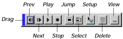
text_image
Prev Play Jump Setup View Drag Next Stop Select DeleteThe tool bar includes the following buttons:
Drag ...... Drags to move the tool bar (for USB mouse operation only).
Prev ...... Returns to the previous slide or folder. Or this lets you play slides back in reverse.
Next ...... Advances to the next slide or folder. Or this lets you play slides back.
Play ...... Plays back automatically or manually depending on the setting on PC Card Viewer Options of the menu. This allows you to move on to the next slide when “Manual Play” is selected.
Stop ...... This allows you to stop Auto Play while you are playing back and to resume playing from the selected slide or folder when "Auto Play" is selected.
Jump ...... Displays a list of slides while you are playing back.
Select ...... Displays a list of folders while you are playing back.
Setup ...... Displays the PC Card Viewer Options dialog box on Page 2 of the Setup dialog box.
Delete ...... Deletes a captured slide(s) or all the captured slides in the Capture – specific folder.
View ...... Hides the tool bar while you are playing back. Pressing the MENU button or clicking with the right button of a mouse shows it again.
NOTE: If no PC card is inserted in the PC CARD slot, there is no signal, and a black, blue or logo background is displayed, depending on the setting.
Playback is stopped when SLIDE +/- on the remote control or ◀/▶ button on the cabinet is pressed in Auto Play mode.
NOTE: Up to 12 indexes can be displayed on the list of folders. The folder in the right bottom is always a folder exclusively for captured images, but is only displayed when images have been captured. To display the list of folders when there are 13 or more indexes stored on the PC card, select "Edit index" from the PC Card Viewer software's "File" menu and move the index you want to display to within 12 indexes from the top of the folder index. For details on indexes, refer to the PC Card Viewer software's help folder.
When the tool bar is not displayed:
Press the FOLDER LIST button on the remote control to display folders from a PC card in the projector's PC Card slot.
Multi cursor (blue marks)
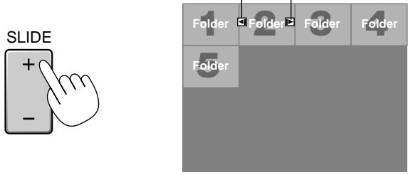
text_image
SLIDE + - Folder 2 Folder 3 Folder FolderUse the SLIDE +/- button to advance to the next folder or return to the previous folder.
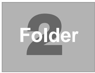
text_image
FolderSlide(Table) cursor (green marks)
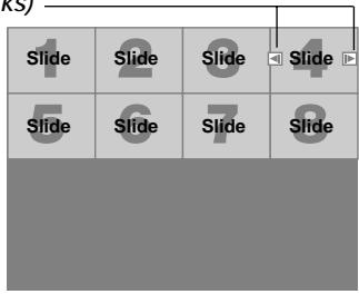
text_image
Slide Slide Slide Slide Slide Slide SlideUse the SLIDE +/- button to advance to the next slide or return to the previous slide.
text_image
4 SlideNOTE: You can also use the ◀ and ▶ button on the remote control to select folders or slides.
If you use the ◀ and ▶ button on the remote control for PC Card Viewer operation, press the PJ button to switch to the Projector mode and the PJ button lights red.
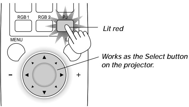
text_image
RGB 1 RGB 2 PJ Lit red MENU Works as the Select button on the projector. - +Auto Play Mode
- If the “Auto Play” option is selected in “PC Card Viewer Options” of the menu, any given slide will start to play automatically. You can also specify Auto Play Interval between 5 and 300 seconds.
Switching to Slides Directly from Other Input Modes
With this function it is possible to switch directly to a slide when the picture of a VCR or computer is being projected.
Example:
When conducting presentations using a combination of slides and moving pictures from a VCR, etc., it is possible to switch from a PC Card Viewer slide to the video picture then back to the PC Card Viewer slide simply by using a source button and PC CARD button.
NOTE: Even if you switch the current PC Card Viewer source to another source, the current slide is retained. When you return back to the PC Card Viewer, you will get the slide that has been retained.
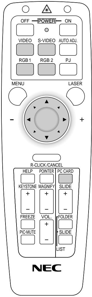
text_image
OFF POWER ON VIDEO S-VIDEO AUTO ADJ. RGB 1 RGB 2 PJ MENU LASER - + R-CLICK/CANCEL HELP POINTER PC CARD KEYSTONE MAGNIFY SLIDE + - FREEZE VOL. FOLDER PIC-MUTE + - SLIDE LIST NECNOTE: The PC card editing operation cannot be performed from the projector. Do so using the PC Card Viewer software.
Capturing Images Displayed on the Projector
Storing images displayed on the projector on the PC card
Preparations:
Insert the PC card into the card slot.
Insert the PC card with the side with the insertion direction arrow on the top.
* Press the eject button to eject the card.
-
Project the image you wish to store on the projector.
-
Select the "Capture" from the Tools menu.
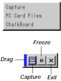
text_image
Capture PC Card Files ChalkBoard Freeze Drag Capture Exit3. A tool bar will appear.
The tool bar includes the following buttons:
Drag ...... Drags to move the tool bar (for USB mouse operation only).
Capture ...... Captures an image and save it as a JPEG file in a PC card.
Freeze ...... Freezes and unfreezes images.
Exit...... Exits the Capture function. Another option to exit the Capture function is to press MENU or CANCEL button on the remote control or projector cabinet.
NOTE: You can compress a captured file (JPEG) using the Capture Options in the Setup dialog. See page E-36.
NOTE: Captured images with higher resolution than the projector's native resolution cannot be displayed correctly.
NOTE:
- File size of the captured image varies depending on the resolution of an input signal.
- Since an image data is compressed with the JPEG format, the image is slightly degraded.
NOTE: An hourglass indicating that an image is being captured appears on the projector's display. Do not eject the PC card or turn off the projector's power while this icon is displayed. Doing so will damage the PC card data. If the PC card data is damaged, use a computer to repair the data.
NOTE: The folder in the right bottom is always a folder exclusively for captured images. To display the list of folders when there are 13 or more indexes stored on the PC card, select "Edit index" from the PC Card Viewer software's "File" menu and move the index you want to display to within 12 indexes from the top of the folder index. For details on indexes, refer to the PC Card Viewer software's help file.
Deleting Captured Images
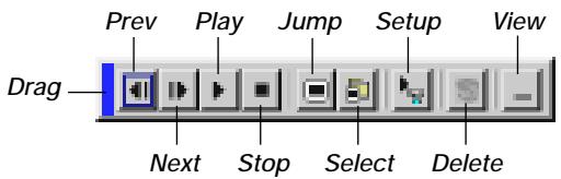
text_image
Prev Play Jump Setup View Drag Next Stop Select DeleteUsing the Delete button on the tool bar for PC Card Viewer can delete captured images.
To delete captured images:
- Select PC Card Viewer.
- Use ▶ button to select the Capture folder in the right bottom of the screen.
- Press the MENU button to display the tool bar.
- Use the ◀ or ▶ button to select the Delete icon and press the ENTER button or click with a mouse button.
Viewing Digital Images
Digital images can be played with the PC Card Viewer if the following conditions are met:
- If the image can be stored on an MS-DOS format PC card
- If the image can be stored in a format supported by the PC Card Viewer.
With the PC Card Viewer, images on the card are searched for in directories and images in JPEG or BMP format are recognized as slides.
Searchable directories are directories within two steps from the root directory, and searchable images are images within the first 12 files in the directory. Only file and slide switching are possible.
NOTE: The maximum number of images recognized as slides within one directory is 128.
Uninstalling the PC Card Viewer Software
Even if you do now know the PC Card Viewer software's file names or where they are stored, the PC Card Viewer software files can be easily removed from the system using the "Install/Uninstall Applications" control panel in Windows. (Normally there is no need to perform this operation.)
Uninstalling the software
Use the procedure described below to uninstall the PC Card Viewer software files.
- From the "Start" menu, select "Settings" then "Control Panels".
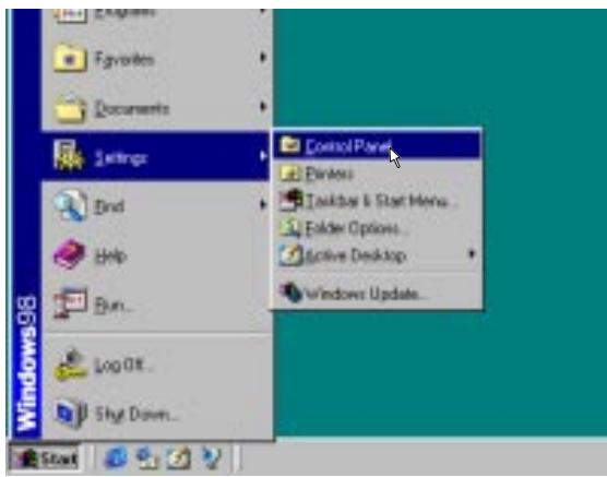
text_image
Windows 98 Start Settings End Help Run... Log Off Shy Down... Control Panel Delete Pausebox & Start Menu... Folder Options... Active Desktop Windows Update...- In the "Control Panels" dialog box, double-click on "Add/Remove Programs".
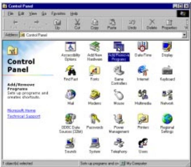
text_image
Control Panel Add/Remove Programs Sets up programs and created shortcuts. Microsoft Items Technical Support 1 obiect(s) selected Sets up programs and on My Computer- In the "Add/Remove Programs Properties" dialog box, click the "Setup/Remove" tab, then select "PC Card Viewer Utility 1.0" from the list of applications and click on "Add/Remove".
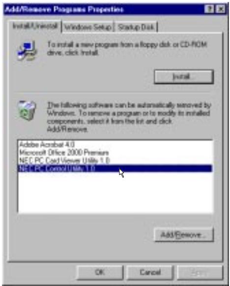
text_image
Add/Remove Programs Properties Install/Uninstall Windows Setup Startup Disk To install a new program from a floppy disk or CD-ROM drive, click Install. Install. The following software can be automatically removed by Windows. To remove a program or to modify its installed components, select it from the list and click Add/Remove. Adobe Acrobat 4.0 Microsoft Office 2000 Premiums NEC PC Cord Viewer Utility 1.0 NEC PC Control Utility 1.0 Add/Remove... OK Cancel Help- In the "Confirm File Deletion" dialog box, click "Yes".

text_image
Cancel File Delete Are you sure you need to completely remove the selected application and all of its components? Yes No- Once the application is uninstalled, click on "OK" in the "Remove Program From Your Computer" dialog box.
Terminology
| PC card | This is the name of a card currently being standardized by the Japan Electronic Industry Association (JEIDA) and PCMCIA (Personal Computer Memory Card Interface Association) of the United States. |
| ATA card | A type of PC card. ATA was originally a type of interface between computers and fixed disk devices. The ATA card is a standard card-type recording medium. |
| CompactFlash | CompactFlash card is a small removable card conforming to ATA specifications. It is one-fourth the volume of a PCMCIA card. |
| TYPE (I, II and III) | PCMCIA 2.1 PC cards are divided into three types according to their thickness: Type I (3.3 mm), Type II (5.0 mm) and Type III (10.5 mm). |
| BMP | A type of image format. The standard Windows Bit Map format used for MS-DOS/Windows-compatible computers. |
| JPEG | A type of image format. "JPEG" is the abbreviation of Joint Photographic Experts Group. JPEG compression offers efficient data storage. The data not required for displaying the image is identified and deleted. Since the data is deleted, JPEG algorithms are said to be irreversible. This means that once the image is compressed, the decompressed image it is not the same as the original image. |
4. MAINTENANCE
This section describes the simple maintenance procedures you should follow to replace the lamp and clean the filter.
Replacing the Lamp
After your lamp has been operating for 1500 hours (2500 hours : Eco mode) or longer, the “Status” light in the cabinet will go on and the message will appear. Even though the lamp may still be working, replace it at 1500 (2500 hours : Eco mode) hours to maintain optimal projector performance.
CAUTION
- DO NOT TOUCH THE LAMP immediately after it has been used. It will be extremely hot. Turn the projector off, wait a full minute, and then disconnect the power cable. Allow at least one hour for the lamp to cool before handling.
- DO NOT REMOVE ANY SCREWS except the lamp cover screw and three lamp case screws. You could receive an electric shock.
- The projector will turn off and go into stand by mode after 1600 (2600 hours : Eco mode) hours of service. If this happens, be sure to replace the lamp. If you continue to use the lamp after 1500 hours (2500 hours : Eco mode) of use, the lamp bulb may shatter, and pieces of glass may be scattered in the lamp case. Do not touch them as the pieces of glass may cause injury. If this happens, contact your NEC dealer for lamp replacement.
To replace the lamp:
- Loosen the lamp cover screw until the screwdriver goes into a freewheeling condition and remove the lamp cover. The lamp cover screw is not removable.
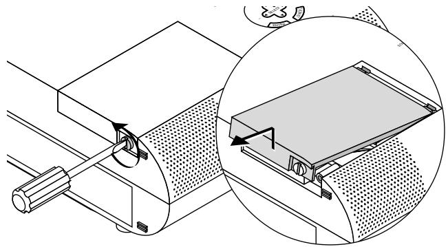
natural_image
Technical diagram of a mechanical assembly with an inset showing a close-up of a component (no text or symbols present)- Loosen the two screws securing the lamp housing until the screw-driver goes into a freewheeling condition. The three screws are not removable.
Remove the lamp housing by pulling out the handle.
NOTE: There is an interlock on this case to prevent the risk of electrical shock. Do not attempt to circumvent this interlock.
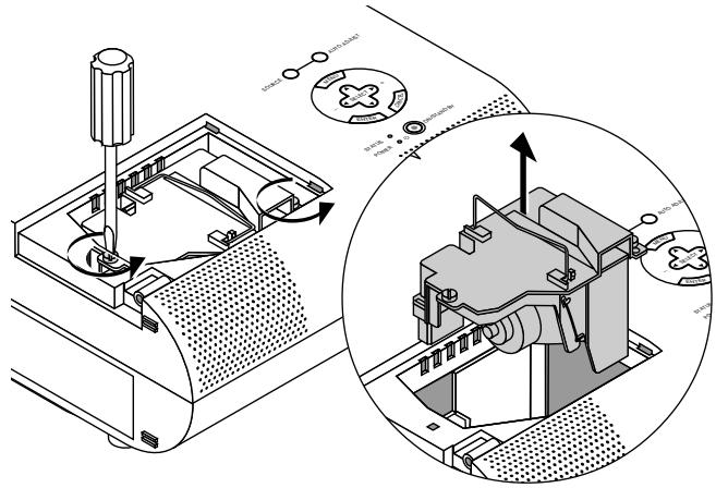
text_image
Technical diagram of a device with labeled components and an inset view showing internal components with directional arrows.- Insert a new lamp housing until the lamp housing is plugged into the socket.
CAUTION: Do not use a lamp other than the NEC replacement lamp (MT50LP). Order this from your NEC dealer.
Secure it in place with the two screws.
Be sure to tighten the screws.
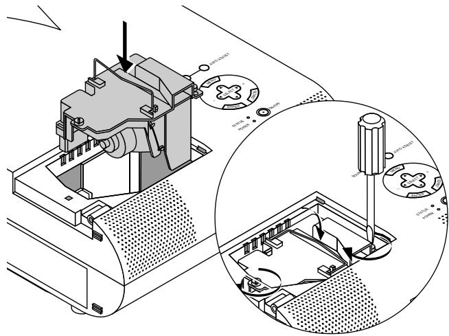
text_image
Technical diagram of a device with labeled components and a magnified inset showing internal wiring connections.- Reattach the lamp cover.
Tighten the lamp cover screw.
Be sure to tighten the screw.
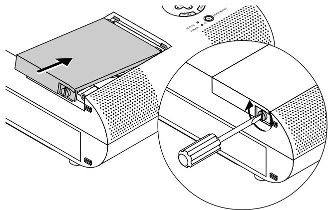
natural_image
Technical illustration of a mechanical device with an inset close-up showing internal components (no text or symbols)- After you install a new lamp, select [Menu] → [Projector Options] → [Setup] → [Page 4] → [Clear Lamp Hour Meter] to reset the lamp usage hours.
NOTE: When the lamp exceeds 1600 hours (2600 hours : Eco mode) of service, the projector cannot turn on and the message is not displayed. If this happens, press the OFF or Help button on the remote control for a minimum of 10 seconds while in standby mode. When the lamp time clock is reset to zero, the STATUS indicator goes out.
Cleaning or Replacing the Filters
The air-filter sponge keeps the inside of the MultiSync MT1055/MT1050/MT850 Projector free from dust or dirt and should be cleaned after every 100 hours of operation (more often in dusty conditions). If the filter is dirty or clogged, your projector may overheat.
CAUTION
- Turn off the power and unplug the projector before replacing the filter.
- Only clean the outside of the filter cover with a vacuum cleaner.
- Do not attempt to operate the projector without a filter cover.
- Your projector will not operate unless the filter cover is installed correctly.
To clean the air-filter:
Vacuum the filter-through the filter cover.
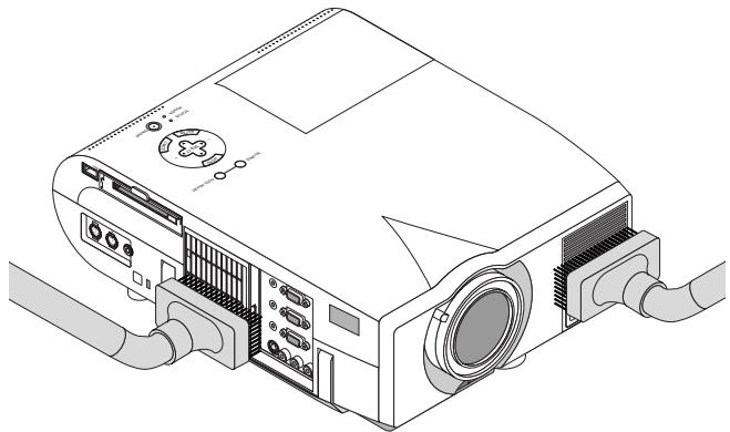
natural_image
Line drawing of a projector with ports and cables (no text or symbols)To replace the air-filter:
- Remove the filter cover by pushing up on the catch of the cover until you feel it detach.
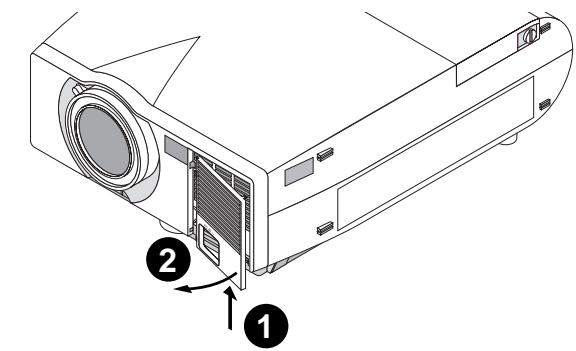
text_image
Diagram of a projector with labeled parts and directional arrows indicating components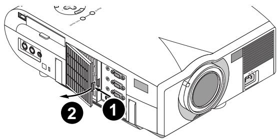
text_image
Diagram of a projector with labeled parts and numbered annotations- Reinstall the new filter cover.
NOTE: Do not detach the sponge from the filter cover. Do not wash the filter cover with soap and water. Soap and water will damage the filter membrane. Before replacing the filter cover, remove dust and dirt from the projector cabinet. Keep out dust and during filter replacement.
5. TROUBLESHOOTING
This section helps you resolve problems you may encounter while setting up or using the projector.
Power/ Status Light Messages
| Condition | Power Indicator | Status Indicator | Note |
| Standby | Steady orange | - | - |
| Cooling down | Blinking green | - | Blinks green for 60 seconds |
| Lamp in High-Bright mode | Steady green | - | - |
| Lamp in Eco mode | Steady green | Steady green | - |
| 3 minutes after lamp is turned on in Eco mode | Steady green | Blinking green | Fixed at High-Bright mode. Lamp mode can be changed on the menu |
| Lamp has reached its end of life (1500 hours or over) | Steady green | Steady red (High-Bright mode)/ Steady orange (Eco mode) | Message appears on screen during 1500-1600 hours of lamp usage. The projector reaches its end of life. Please replace the lamp as soon as possible. |
| Lamp life has reached its end of life (1600 hours or over) | Steady orange | Steady red | The projector is in standby mode and cannot be turned on. |
| Lamp or filter cover error (3 locations) | Steady orange | Blinking red (1 sec interval) | The projector is in standby mode and cannot be turned on. |
| Temperature error | Steady orange | Blinking red (4 sec interval) | The projector is in standby mode and cannot be turned on. |
| Fan error | Steady orange | Blinking red (8 sec interval) | The projector is in standby mode and cannot be turned on. |
| Lamp error | Steady orange | Blinking red (12 sec interval) | The projector is in standby mode and cannot be turned on. |
Common Problems & Solutions
| Problem | Check These Items |
| Does not turn on | Check that the power cable is plugged in and that the power button on the projector cabinet or the remote control is on.Ensure that the lamp cover is installed correctly. See page E-47.Check to see if the projector has overheated or the lamp usage exceeds 1600 hours (2600 hours in Eco mode). If there is insufficient ventilation around the projector or if the room where you're presenting is particularly warm, move the projector to a cooler location. |
| No picture | Use the menu to select your source (Video, S-Video, RGB1, RGB2 or PC Card Viewer). See page E-32.Ensure your cables are connected properly.Use menus to adjust the brightness and contrast. See page E-32.Remove the lens cap.Reset the settings or adjustments to factory preset levels using the Factory Default on the Image Options Menu in Advanced menu. See page E-35. |
| Image isn't square to the screen | Reposition the projector to improve its angle to the screen. See page E-14.Use the Keystone to correct the trapezoid distortion. See page E-28 or 33. |
| Picture is blurred | Adjust the focus. See page E-25.Reposition the projector to improve its angle to the screen. See page E-14.Ensure that the distance between the projector and screen is within the adjustment range of the lens. See page E-17. |
| Image is scrolling vertically, horizontally or both | Use menus or a source button on the remote control or the cabinet to select the source you want to input. |
| Remote control does not work | Install new batteries. See page E-12.Make sure there are no obstacles between you and the projector.Stand within 22 feet (7 m) of the projector. See page E-12.Make sure that you are in the Projector mode or the PJ button lights in red. If not, press the PJ button. |
| Status indicator is lit or blinking | See the Power/ Status Light messages above. |
| Cross color in RGB mode | If Auto Adjust is off, turn it on. If Auto Adjust is on, turn it off and balance the image with the Position and Clock Adjust on the Advanced Options Menu. See page E-34. |
When using the PC Card Viewer function
| Condition | Status |
| No picture | Is “PC Card Viewer” selected from the Source menu?Is the PC card seated in the PC CARD slot completely?Are slide data stored in the PC card?Have the contents of the PC card been destroyed? |
| Part of a slide is not displayed | While an image with over 1024×768 dots (MT850: 800×600 dots) is projected, several lines of information will be lost. Use the supplied software change the image to 1024×768 dots in size. |
| Contents of PC Card are damaged | Use a computer, etc., to repair the data. |
For more information contact your dealer.
This section provides technical information about the MultiSync MT1055/MT1050/MT850 Projector's performance.
Model Number MT1055/MT1050/MT850
Optical
| LCD Panel | 1.3" p-Si TFT active-matrix, 800×600 dots (MT850) / 1024×768 dots (MT1055/MT1050) |
| 1.3" p-Si TFT active-matrix with Micro Lens Array (MT1055) | |
| Lens | Manual zoom, manual focus |
| MT1050/MT850 : F2.3 – 2.7 f=48.6 – 58.4 mm | |
| MT1055 : F1.8 – 2.2 f=49.3 – 59.3 mm | |
| Lamp | 200W NSH lamp (160W in Eco mode) |
| The lamp, under normal operating conditions, is warranted for 1500 hours of operation time within 6 months. | |
| Image Size | 30 – 300 inches (762 – 7620 mm) diagonal |
| Projection Distance | MT1050/MT850 : 4.3 – 36.7 ft (1.3 - 11.2 m) |
| MT1055 : 4.3 – 37.1 ft (1.3 - 11.3 m) |
Electrical
| Inputs | Video (NTSC / PAL / PAL60 / SECAM / NTSC4.43)Horizontal Frequency : 15 – 100 kHz (RGB : 24 kHz or over)Vertical Frequency : 50 – 120 Hz |
| Video Bandwidth | RGB: 80 MHz |
| Color | Reproduction Full color, 16.7 million colors simultaneously. |
| Horizontal Resolution | 550 TV lines : NTSC / PAL / NTSC4.43 / YCbCr350 TV lines : SECAMRGB MT850 : 800 dots horizontal, 600 dots verticalMT1055/MT1050 : 1024 dots horizontal, 768 dots vertical |
| Power Requirement | 100 – 120 / 200 – 240 VAC, 50 / 60 Hz |
| Input Current | 3.5 A (100 – 120 VAC) / 1.7A (200 – 240 VAC) |
Mechanical
| Dimensions | MT1050/MT850 : 11.1" (W) × 4.8" (H) × 14.3" (D) / 281mm (W) × 121mm (H) × 364mm (D) (not including lens and feet) |
| MT1055 : 11.1" (W) × 4.8" (H) × 14.9" (D) / 281mm (W) × 121mm (H) × 376mm (D) (not including lens and feet) | |
| Net Weight | MT1050/MT850 : 13.0 lbs / 5.9 kg |
| MT1055 : 13.3 lbs / 6.0 kg | |
| Environmental Considerations | Operational Temperatures: 32^ - 104^ ( 0^ to 40^ ), 20 – 80% humidity |
| Storage Temperatures: 14^ - 122^ (- 10^ to 50^ ), 20 – 80% humidity | |
| Regulations | UL Approved (UL 1950, CSA 950) |
| Meets DOC Canada Class B requirements | |
| Meets FCC Class B requirements | |
| Meets AS/NZS3548 Class B | |
| Meets EMC Directive (EN55022, EN55024, EN61000-3-2, EN61000-3-3) | |
| Meets Low Voltage Directive (EN60950, TUV GS Approved) |
CE
Cabinet Dimensions
MT1055
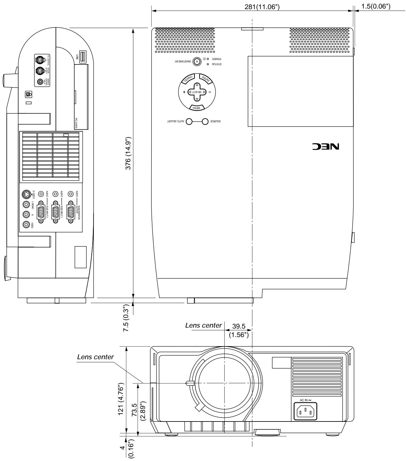
text_image
281(11.06") 1.5(0.06") 376 (14.9') 7.5 (0.3") Lens center 39.5 (1.56") Lens center 121 (4.76") 73.5 (2.89") 4 (0.16") NEC POWER ON/STAND BY STATUS OFF AUTO AC IN~ AC IN~ OUTPUT ON/OFF OUTPUT OUTPUT OUTPUT OUTPUT OUTPUT OUTPUT OUTPUT OUTPUT OUTPUT OUTPUT OUTPUT OUTPUT OUTPUT OUTPUTUnit = mm (inch)
MT1050/MT850
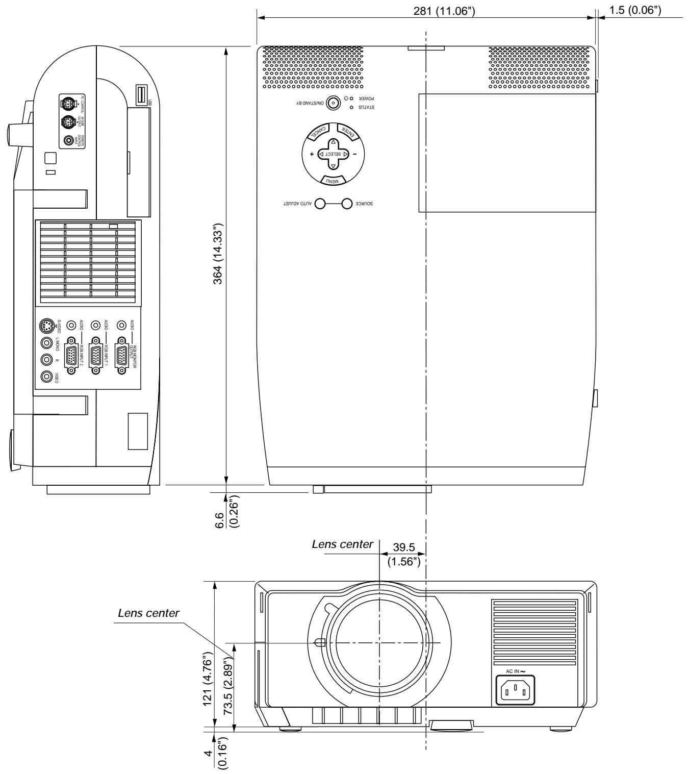
text_image
281 (11.06") 1.5 (0.06") 364 (14.33") 6.6 (0.26") Lens center 39.5 (1.56") Lens center 121 (4.76") 73.5 (2.89") 4 (0.16") AC IN~ OUTPUT/STAND BY POWER START AUTO AUTO ADJUST ON/OFF ON/OFF ON/OFF ON/OFF ON/OFF ON/OFF ON/OFF ON/OFF ON/OFF ON/OFF ON/OFF ON/OFF ON/OFF ON/OFF ON/OFF ON/OFF ON/OFF ON/OFF ON/OFF ON/OFF ON/OFF ON/OFF ON/OFF ON/OFF ON/OFF ON/OCC ON/OCC ON/OCC ON/OCC ON/OCC ON/OCC ON/OCC ON/OCC ON/OCC ON/OCC ON/OCC ON/OCC ON/OCC ON/OCC ON/OCC ON/OCC ON/OCC ON/OCC ON/OCC ON/OCC ON/OCC ON/OCC ON/OCC ON/OCC ON/OCC ON/Occ ON/Occ ON/Occ ON/Occ ON/Occ ON/Occ ON/Occ ON/Occ ON/Occ ON/Occ ON/Occ ON/Occ ON/Occ ON/Occ ON/Occ ON/Occ ON/Occ ON/Occ ON/Occ ON/Occ ON/Occ ON/Occ ON/Occ ON/Occ ON/Occ ON/OcscUnit = mm (inch)
D-Sub Pin Assignments
Mini D-Sub 15 Pin Connector
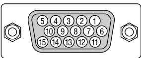
Signal Level
Video signal : 0.7Vp-p (Analog)
Sync signal : TTL level
* RGB Input 1 only
| Pin No. | RGB Signal (Analog) | YCbCr Signal |
| 1 | Red | Cr |
| 2 | Green or Sync on Green | Y |
| 3 | Blue | Cb |
| 4 | Ground | |
| 5 | Ground | |
| 6 | Red Ground | Cr Ground |
| 7 | Green Ground | Y Ground |
| 8 | Blue Ground | Cb Ground |
| 9 | No Connection | |
| 10 | Sync Signal Ground | |
| 11 | Ground | |
| 12 | Bi-directional DATA (SDA)* | |
| 13 | Horizontal Sync or Composite Sync | |
| 14 | Vertical Sync | |
| 15 | Data Clock* |
Timing Chart
| Y / N | Signal | Resolution ( Dots ) | Frequency H. ( kHz ) | Refresh Rate ( Hz ) | Dot Clock ( MHz ) |
| Y | NTSC | 640 × 480 | 15.734 | 60 | - |
| Y | PAL | 768 × 576 | 15.625 | 50 | - |
| Y | SECAM | 768 × 576 | 15.625 | 50 | - |
| Y | VESA | 640 × 480 | 31.47 | 59.94 | 25.175 |
| Y | IBM | 640 × 480 | 31.47 | 60 | 25.175 |
| Y | MAC | 640 × 480 | 31.47 | 60 | 25.175 |
| Y | MAC | 640 × 480 | 34.97 | 66.67 | 31.334 |
| Y | MAC | 640 × 480 | 35 | 66.67 | 30.24 |
| Y | VESA | 640 × 480 | 37.86 | 72.81 | 31.5 |
| Y | VESA | 640 × 480 | 37.5 | 75 | 31.5 |
| Y | IBM | 640 × 480 | 39.375 | 75 | 31.49 |
| Y | VESA | 640 × 480 | 43.269 | 85.01 | 36 |
| Y | IBM | 720 × 350 | 31.469 | 70.09 | 28.322 |
| Y | VESA | 720 × 400 | 37.927 | 85.04 | 35.5 |
| Y | IBM | 720 × 350 | 39.44 | 87.85 | 35.5 |
| Y | IBM | 720 × 400 | 39.375 | 87.7 | 35.5 |
| Y | VESA | 800 × 600 | 35.16 | 56.25 | 36 |
| Y | VESA | 800 × 600 | 37.879 | 60.32 | 40 |
| Y | VESA | 800 × 600 | 48.077 | 72.19 | 50 |
| Y | VESA | 800 × 600 | 46.88 | 75 | 49.5 |
| Y | VESA | 800 × 600 | 53.674 | 85.06 | 56.25 |
| #Y | MAC | 832 × 624 | 49.725 | 74.55 | 57.283 |
| #Y | VESA | 1024 × 768 | 35.5 | 43 Interlaced | 44.9 |
| #Y | VESA | 1024 × 768 | 48.363 | 60 | 65 |
| #Y | VESA | 1024 × 768 | 57.476 | 70.07 | 75 |
| #Y | IBM | 1024 × 768 | 58.131 | 72.03 | 79 |
| #Y | MAC | 1024 × 768 | 60.241 | 74.93 | 80 |
| #Y | VESA | 1024 × 768 | 60.023 | 75.03 | 78.75 |
| #Y | VESA | 1024 × 768 | 68.677 | 85 | 94.5 |
| ##Y | VESA | 1152 × 864 | 67.5 | 75 | 108 |
| ##Y | MAC | 1152 × 870 | 68.681 | 75.06 | 100 |
| ##Y | SUN | 1152 × 900 | 61.796 | 65.95 | 92.94 |
| ##Y | SGI | 1152 × 900 | 71.736 | 76.05 | 105.6 |
| ##Y | VESA | 1280 × 960 | 60 | 60 | 108 |
| ##Y | SGI | 1280 × 1024 | 63.9 | 60 | 107.35 |
| ##Y | VESA | 1280 × 1024 | 63.981 | 60.02 | 108 |
| ##Y | MAC | 1280 × 1024 | 64.31 | 60.38 | 107 |
| ##Y | MAC | 1280 × 1024 | 69.9 | 65.2 | 118.5 |
| ##Y | HP | 1280 × 1024 | 78.125 | 72.01 | 135 |
| ##Y | SUN | 1280 × 1024 | 81.13 | 76.11 | 135 |
| ##Y | VESA | 1280 × 1024 | 79.976 | 75.03 | 135 |
| ##Y | VESA | 1280 × 1024 | 91.146 | 85.02 | 157.5 |
| ##Y | HDTV (1080i)(1125i) | 1920 × 1080 | 33.75 | 60 Interlace | 74.25 |
| ##Y | HDTV (720p)(750p) | 1280 × 720 | 45 | 60 Progressive | 74.25 |
| ##Y | SDTV (480p)(525p) | 720 × 483 | 31.47 | 59.94 Progressive | 27 |
| ##Y | SDTV (480i)(525i) | 720 × 480 | 15.73 | 59.9 Interlace | - |
| ##Y | VESA | 1600 × 1200 | 75.0 | 60 | 162 |
| ##Y | VESA | 1600 × 1200 | 81.3 | 65 | 175.5 |
| ##Y | VESA | 1600 × 1200 | 87.5 | 70 | 189 |
| ##Y | VESA | 1600 × 1200 | 93.75 | 75 | 202.5 |
Y: Images in above flagged with # and Y are compressed with Advanced AccuBlend on MT850 only.
Y: Images in above flagged with ## and Y are compressed with Advanced AccuBlend on MT1055/MT1050 and MT850.
NOTE1: Some composite sync signals may not be displayed correctly.
NOTE2: Signals other than those specified in the table above may not be displayed correctly. If this should happen, change the refresh rate or resolution on your PC. Refer to Display Properties help section of your PC for procedures.
NOTE3: UXGA can be supported for separate sync signal only.
PC Control Codes
| Function | Code Data | ||||||
| POWER ON | 02H | 00H | 00H | 00H | 00H | 02H | |
| POWER OFF | 02H | 01H | 00H | 00H | 00H | 03H | |
| INPUT SELECT RGB 1 | 02H | 03H | 00H | 00H | 02H | 01H | 01H 09H |
| INPUT SELECT RGB 2 | 02H | 03H | 00H | 00H | 02H | 01H | 02H 0AH |
| INPUT SELECT VIDEO | 02H | 03H | 00H | 00H | 02H | 01H | 06H 0EH |
| INPUT SELECT S-VIDEO | 02H | 03H | 00H | 00H | 02H | 01H | 0BH 13H |
| INPUT SELECT PC CARD VIEWER | 02H | 03H | 00H | 00H | 02H | 01H | 1FH 27H |
| PICTURE MUTE ON | 02H | 10H | 00H | 00H | 00H | 12H | |
| PICTURE MUTE OFF | 02H | 11H | 00H | 00H | 00H | 13H | |
| SOUND MUTE ON | 02H | 12H | 00H | 00H | 00H | 14H | |
| SOUND MUTE OFF | 02H | 13H | 00H | 00H | 00H | 15H | |
| ON SCREEN MUTE ON | 02H | 14H | 00H | 00H | 00H | 16H | |
| ON SCREEN MUTE OFF | 02H | 15H | 00H | 00H | 00H | 17H | |
NOTE: Contact your local dealer for a full list of the PC Control Codes if needed.
Cable Connection
Communication Protocol
| Baud rate: | 38400 bps |
| Data length: | 8 bits |
| Parity: | No parity |
| Stop bit: | One bit |
| X on/off: | None |
| Communications procedure: | Full duplex |
PC Control Connector (DIN-8P)
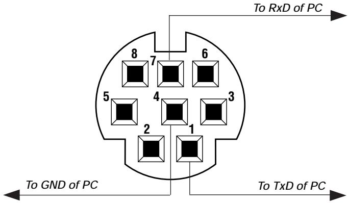
text_image
To GND of PC To TxD of PC To RxD of PC 8 7 6 5 4 3 2 1NOTE: Pins 2, 3, 5, 6 and 8 are used inside the projector.