HT1100 - Projector NEC - Free user manual and instructions
Find the device manual for free HT1100 NEC in PDF.

User questions about HT1100 NEC
0 question about this device. Answer the ones you know or ask your own.
Ask a new question about this device
Download the instructions for your Projector in PDF format for free! Find your manual HT1100 - NEC and take your electronic device back in hand. On this page are published all the documents necessary for the use of your device. HT1100 by NEC.
USER MANUAL HT1100 NEC
Please read this manual carefully before using your NEC HT1100 Projector and keep the manual handy for future reference. Your serial number is located on the bottom of your projector. Record it here:

CAUTION
To turn off main power, be sure to remove the plug from power outlet.
The power outlet socket should be installed as near to the equipment as possible, and should be easily accessible.

CAUTION
TO PREVENT SHOCK, DO NOT OPEN THE CABINET. NO USER-SERVICEABLE PARTS INSIDE. REFER SERVICING TO QUALIFIED NEC SERVICE PERSONNEL.

This symbol warns the user that uninsulated voltage within the unit may be sufficient to cause electrical shock. Therefore, it is dangerous to make any kind of contact with any part inside of the unit.

This symbol alerts the user that important information concerning the operation and maintenance of this unit has been provided.
The information should be read carefully to avoid problems.
WARNING
TO PREVENT FIRE OR SHOCK,DO NOT EXPOSE THIS UNIT TO RAIN OR MOISTURE.
DO NOT USE THIS UNIT'S GROUNDED PLUG WITH AN EXTENSION CORD OR IN AN OUTLET UNLESS ALL THREE PRONGS CAN BE FULLY INSERTED.
DO NOT OPEN THE CABINET.THERE ARE HIGH-VOLTAGE COMPONENTS INSIDE. ALL SERVICING MUST BE DONE BY QUALIFIED NEC SERVICE PERSONNEL.
DOC Compliance Notice
This Class B digital apparatus meets all requirements of the Canadian Interference-Caising Equipment Regulations.
Acoustic Noise Information Ordinance -3. GSGV:
The sound pressure level is less than 70 dB (A) according to ISO 3744 or ISO 7779.
RF Interference
WARNING
The Federal Communications Commission does not allow any modifications or changes to the unit EXCEPT those specified by NEC Solutions (America), Inc. in this manual. Failure to comply with this government regulation could void your right to operate this equipment. This equipment has been tested and found to comply with the limits for a Class B digital device, pursuant to Part 15 of the FCC Rules. These limits are designed to provide reasonable protection against harmful interference in a residential installation. This equipment generates, uses, and can radiate radio frequency energy and, if not installed and used in accordance with the instructions, may cause harmful interference to radio communications. However, there is no guarantee that interference will not occur in a particular installation. If this equipment does cause harmful interference to radio or television reception, which can be determined by turning the equipment off and on, the user is encouraged to try to correct the interference by one or more of the following measures:
- Reorient or relocate the receiving antenna.
- Increase the separation between the equipment and receiver.
- Connect the equipment into an outlet on a circuit different from that to which the receiver is connected.
- Consult the dealer or an experienced radio / TV technician for help.
In UK, a BS approved power cable with moulded plug has a Black (five Amps) fuse installed for use with this equipment. If a power cable is not supplied with this equipment please contact your supplier.
Important Safeguards
These safety instructions are to ensure the long life of your projector and to prevent fire and shock. Please read them carefully and heed all warnings.
Installation
- For best results, use your projector in a darkened room.
- Place the projector on a flat, level surface in a dry area away from dust and moisture.
- Do not place your projector in direct sunlight, near heaters or heat radiating appliances.
- Exposure to direct sunlight, smoke or steam can harm internal components.
- Handle your projector carefully. Dropping or jarring can damage internal components.
- Do not place heavy objects on top of the projector.
- If you wish to have the projector installed on the ceiling:
a. Do not attempt to install the projector yourself.
b. The projector must be installed by qualified technicians in order to ensure proper operation and reduce the risk of bodily injury.
c. In addition, the ceiling must be strong enough to support the projector and the installation must be in accordance with any local building codes.
d. Please consult your dealer for more information.
WARNING TO CALIFORNIA RESIDENTS:
Handling the cables supplied with this product, will expose you to lead, a chemical known to the State of California to cause birth defects or other reproductive harm. Wash hands after handling.
Fire and Shock Precautions
- Ensure that there is sufficient ventilation and that vents are unobstructed to prevent the build-up of heat inside your projector. Allow at least 4 inches (10 cm) of space between your projector and a wall.
- Prevent foreign objects such as paper clips and bits of paper from falling into your projector.
Do not attempt to retrieve any objects that might fall into your projector. Do not insert any metal objects such as a wire or screwdriver into your projector. If something should fall into your projector, disconnect it immediately and have the object removed by a qualified NEC service personnel.
- Do not place any liquids on top of your projector.
- Do not look into the lens while the projector is on. Serious damage to your eyes could result.
- Keep any items such as magnifying glass out of the light path of the projector. The light being projected from the lens is extensive, therefore any kind of abnormal objects that can redirect light coming out of the lens, can cause unpredictable outcome such as fire or injury to the eyes.
- Do not cover the lens with the supplied lens cap or equivalent while the projector is on. Doing so can lead to melting of the cap and possibly burning your hands due to the heat emitted from the light output.
- The projector is designed to operate on a power supply of 100-120 or 200 - 240V50 / 60Hz AC. Ensure that your power supply fits this requirement before attempting to use your projector.
- Handle the power cable carefully and avoid excessive bending. A damaged cord can cause electric shock or fire.
- If the projector is not to be used for an extended period of time, disconnect the plug from the power outlet.
- Do not touch the power plug during a thunderstorm. Doing so can cause electrical shock or fire.
CAUTION
- Do not try to touch the ventilation outlet on the front and side as it can become heated while the projector is turned on.
- Do not use the tilt-foot for purposes other than originally intended. Misuses such as gripping the tilt-foot or hanging on the wall can cause damage to the projector.
- Do not send the soft carrying case by parcel delivery service or cargo shipment. The projector inside the soft carrying case could be damaged. (However, it is possible to use it as a carriercase on board.)
- Select "High Speed" in the Fan mode if you continue to use the projector for consecutive days. (From the menu, select [Setup] [Page 2] [Fan Mode].)
- Do not unplug the power cable from the wall outlet under any one of the following circumstances.
Doing so can cause damage to the projector:
- While the Hour Glass icon appears.
- While the message "Please wait a moment." appears. This message will be displayed after the projector is turned off.
-
While the cooling fans are running. (The cooling fans continue to work for 90 seconds after the projector is turned off).
-
Do not eject the PC card while its data is being accessed. Doing so can damage your PC card data.
- Do not hold the lens part with your fingers. Doing so could pinch fingers or hands causing injury.
Lamp Replacement
To replace the lamp, follow all instructions provided on page E-43.
- Be sure to replace the lamp when the message "The lamp has reached the end of its usable life. Please replace the lamp." appears. If you continue to use the lamp after the lamp has reached the end of its usable life, the lamp bulb may shatter, and pieces of glass may be scattered in the lamp case. Do not touch them as the pieces of glass may cause injury.
If this happens, contact your NEC dealer for lamp replacement.
- Allow a minimum of 90 seconds to elapse after turning off the projector. Then turn off the main power switch, disconnect the power cable and allow 60 minutes to cool the projector before replacing the lamp.
What's in the Box?
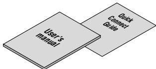
Make sure your box contains everything listed. If any pieces are missing, contact your dealer.
Please save the original box and packing materials if you ever need to ship your HT1100 Projector.
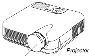
Lens cap (24FT8661)
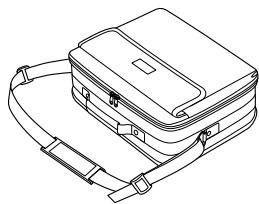
Soft carrying case (24BS7113)
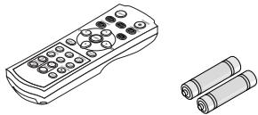
Remote control (7N900441)
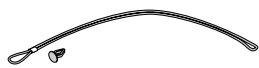
String and rivet (24C05051) (24C04531)
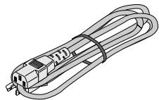
Power cable (7N080204: North America) (7N080003: G model)
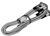
RGB signal cable (7N520012)
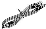
Audio cable (7N520027)
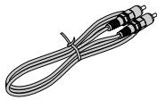
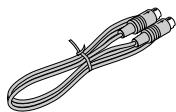
Composite video cable (7N520029)
S-Video cable (7N520028)
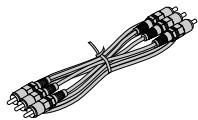
Component video cable (RCA×3-to-RCA×3) (7N520030)
For North America only
Registration card
Limited warranty
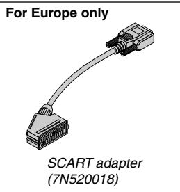
For Europe only Guarantee policy
TABLE OF CONTENTS
IMPORTANT INFORMATION E-2
Safety Cautions E-2
What's in the Box? E-3
INTRODUCTION E-5
Introduction to the Projector E-5
Part Names of the Projector E-6
Attaching the lens cap E-6
Top Features E-7
Terminal Panel Features E-8
Part Names of the Remote Control E-9
Battery Installation. E-10
Remote Control Precautions E-10
Operating Range E-10
INSTALLATION AND CONNECTIONS E-11
Setting Up the Screen and the Projector. E-11
Selecting a Location E-11
Throw Distance and Screen Size. E-12
Making Connections E-13
Wiring Diagram E-13
Connecting Your VCR or Laser Disc Player. E-14
Connecting Your DVD Player . E-15
Connecting Your PC or Macintosh Computer E-16
To connect SCART output (RGB) E-16
When Viewing a DVI Digital Signal E-17
Connecting the Supplied Power Cable. E-17
PROJECTING AN IMAGE (BASIC OPERATION) ...... E-18
Turning on the Projector E-18
Selecting a Source E-19
Adjusting the Picture Size and Position E-19
Correcting the Horizontal and Vertical Keystone Distortion (3D Reform) E-20
Optimizing RGB Picture Automatically. E-21
Turning Up or Down Volume E-22
Turning off the Projector. E-22
CONVENIENT FEATURES E-23
Using Image Position E-23
Turning Off the Image and Sound E-23
Freezing a Picture E-23
Capturing a Picture E-23
Enlarging and Moving a Picture. E-24
Getting the On-line Help E-24
USING ON-SCREEN MENU E-25
Using the Menus E-25
Menu tree E-26
Menu Elements E-28
Menu Descriptions & Functions E-29
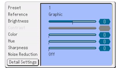
Picture E-29
Preset, Reference, Brightness, Contrast, Color, Hue, Sharpness, Noise Reduction, Detail Settings E-29
Image [Page 1] E-30
Aspect Ratio E-30
Blanking, Position/Clock, Image Position, Overscan, Signal Type, Setup Level, Video Filter E-32
Image [Page 2] E-32
Entry List E-32
Setup [Page 1] E-33
Screen, Orientation, Lamp Mode, Screen Trigger, Background, Language, Test Pattern E-33
Setup [Page 2] E-33
Signal Select, Standby Mode, Fan Mode, Lamp Hour .... E-33
Setting Auto Adjust E-34
Setup [Page 3] E-34
Password (Logo), LAN Mode. E-34
Security E-36
Information E-37
Returning to Factory Default [Reset] E-37
USING THE VIEWER E-38
Making the Most out of the Viewer Function E-38
Operating the Viewer Function from the Projector (playback) ... E-39
Changing Background Logo E-42
MAINTENANCE E-43
Replacing the Lamp. E-43
Cleaning E-44
Lens Protector E-44
TROUBLESHOOTING E-45
SPECIFICATIONS E-47
APPENDIX E-48
Cabinet Dimensions E-48
Pin Assignments of D-Sub COMPUTER Input Connector E-48
Compatible Input Signal List E-49
PC Control Codes and Cable Connection E-50
Cable Connection E-50
PC Control Connector (DIN-8P) E-50
Using Software Keyboard E-50
Operation Using an HTTP Browser E-51
TravelCare Guide E-52
Introduction to the Projector
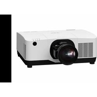
This section introduces you to your new HT1100 Projector and describes the features and controls.
Congratulations on Your Purchase of The HT1100 Projector
The HT1100 is our most sophisticated single chip DLPTM based projector for the commercial and residential entertainment user. With the HT1100 you will enjoy projecting images up to 200^ (measured diagonally) from your DVD player, VCR, satellite hookup, HDTV source, PC or Macintosh computer (desktop or notebook) and images from your digital camera. The HT1100 can be setup on a coffee table, tabletop, cart, bookshelf or permanently installed ^*1 . With an extensive input panel, quick connect guide and full function remote, you will be ready to immerse yourself in big screen enjoyment.
Features you'll enjoy on the HT1100:
- Phenomenal 3500:1 contrast ratio with a variable IRIS that allows you to fine-tune the image contrast
- 3D Reform technology for positioning the projector in off center locations in the room and still get aligned images
- NEC designed and developed SweetVision™ technology for enhanced images, more vibrant colors and blacks richer with detail
- Deinterlace function eliminates jitter or artifacts in HDTV and Video signals
- Ability to display 16:9 and 4:3 aspect ratio sources
HDTV, SDTV compatibility - 3D 10-bit video decoder for expanded black levels and adaptive gamma correction
- Digital photo viewer to display larger than life images from your digital cameras PC or compact flash card
- Easy set up and operation
- High performance long life lamp for low total operating costs
- Eco-mode lamp technology for increased lamp life and energy savings
- Uncompromising display of video and data. Improves white level, color accuracy, dynamic range, and display of varying levels of black in an image.
- Sealed optics for reduced maintenance and better performance in dusty areas
- Wireless remote control operation
Network capable with a wired card for the ability to maintain and control your projector from your computer - Smart security settings for password protection and PC card protection key to help prevent unauthorized use
- Multiple video mode selections depending on your source.
Control the unit with a PC using the PC Control port. - NEC's exclusive Advanced AccuBlend intelligent pixel blending technology - an extremely accurate image compression technology - offers a crisp image with HTDV 1080p (1920 × 1080) resolution2.
Supports most IBM VGA, SVGA, XGA, SXGA (with Advanced AccuBlend)², Macintosh, component signal (YCbCr/YPbPr) or any other RGB signals within a horizontal frequency range of 24 to 100kHz and a vertical frequency range of 48 to 100Hz . This includes NTSC, PAL, PAL-N, PAL-M, PAL60, SECAM and NTSC4.43 standard video signals.
NOTE: Composite video standards are as follows:
NTSC: U.S. TV standard for video in U.S. and Canada.
PAL: TV standard used in Western Europe.
PAL-N: TV standard used in Argentine, Paraguay and Uruguay.
PAL-M: TV standard used in Brazil.
PAL60: TV standard used for NTSC playback on PAL TVs.
SECAM: TV standard used in France and Eastern Europe.
NTSC4.43: TV standard used in Middle East countries.
- You can control the projector with a PC using the PC Control port and wired LAN.
- The contemporary cabinet design is light, compact, easy to carry.
1 Do not attempt to mount the projector on a ceiling yourself. The projector must be installed by qualified technicians in order to ensure proper operation and reduce the risk of bodily injury. In addition, the ceiling must be strong enough to support the projector and the installation must be in accordance with any local building codes. Please consult your dealer for more information.
2 HDTV 1080p (1920×1080), HDTV 1080i (1920×1080) and HDTV 720p (1280×720) are displayed with NEC's Advanced AccuBlend.
Digital Light Processing and DLP are trademarks of Texas Instruments. The specifications are subject to change without notice.
All other trademarks are the property of their respective owners. All specifications subject to change without notice.
Focus Ring (See page E-20)
Part Names of the Projector
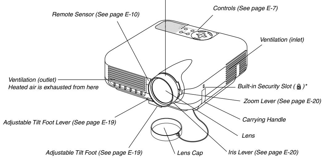
* This security slot supports the MicroSaver® Security System. MicroSaver® is a registered trademark of Kensington Microware Inc. The logo is trademarked and owned by Kensington Microware Inc.
AC Input
Connect the supplied power cable's three-pin plug here, and plug the other end into an active wall outlet. (See page E-17)
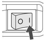
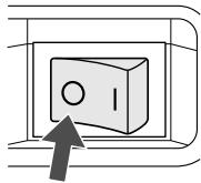
Main Power Switch
When you plug the supplied power cable into an active wall outlet and turn on the Main Power switch, the POWER indicator turns orange and the projector is in standby mode. (See page E-18)
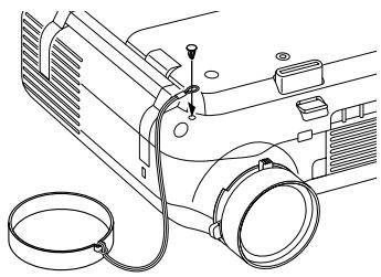
Attaching the lens cap
To attach the lens cap to the bottom with the supplied string and rivet:
- Thread the string through the hole on the lens cap and then tie a knot in the string.
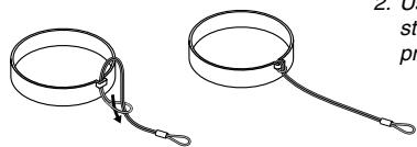
- Use the rivet to attach the string to the bottom of the projector.
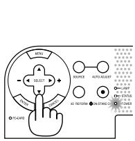
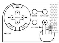
Top Features
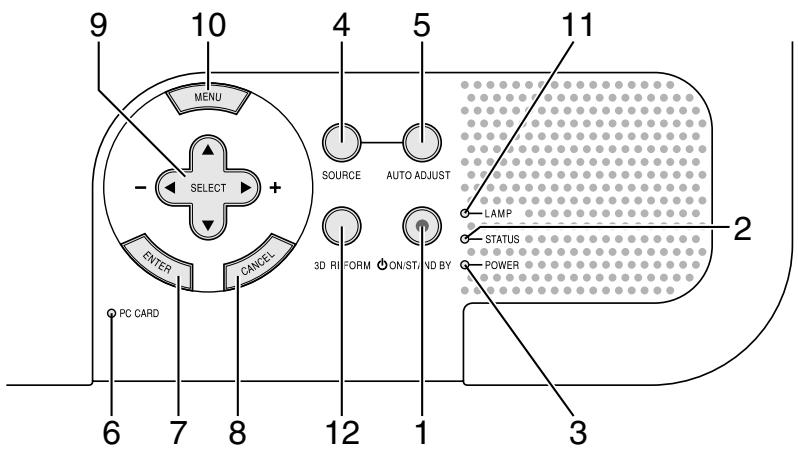
- POWER Button (ON/STAND BY) (0)
Use this button to turn the power on and off when the main power is supplied and the projector is in standby mode (Power-saving mode or Idle mode).
NOTE: To turn on or off the projector, press and hold this button for a minimum of two seconds.
- STATUS Indicator
If this light blinks red rapidly, it indicates that an error has occurred, the lamp cover is not attached properly or the projector has overheated. See the Status Indicator section on page E-45 for more details.
- POWER Indicator
When this indicator is green, the projector is on; when this indicator is orange, it is in standby mode (Power-saving mode or Idle mode). See the Power Indicator section on page E-45 for more details.
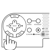
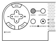
- SOURCE Button
Use this button to select a video source such as a VCR, DVD player, PC or Viewer (PC card).
Press and release this button quickly to display the Source List.
Each time this button is pressed for a minimum of ONE second the input source will change as follows:
Video S-Video Component Computer DVI (DIGITAL) Viewer Video ...
If no input signal is present, the input will be skipped.
- AUTO ADJUST Button
Use this button to adjust Position-H/V and Pixel Clock/Phase for an optimal picture. Some signals may not be displayed correctly or take time to switch between sources.
NOTE: This function may not be available depending upon the input signal.
- PC CARD Access Indicator
Lights while accessing a PC card.
- ENTER Button
Executes your menu selection and activates items selected from the menu.
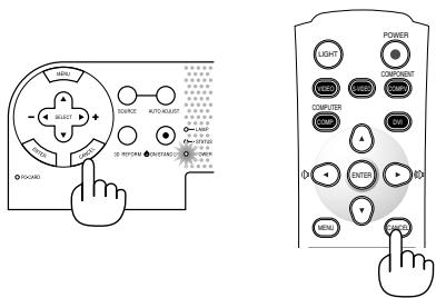
- CANCEL Button
Press this button to exit "Menu". Press this button to return the adjustments to the last condition while you are in the adjustment or setting menu.
- SELECT ▲▼▲▶ (+) (-) / Volume Buttons
: Use these buttons to select the menu of the item you wish to adjust.
: Use these buttons to change the level of a selected menu item. When no menus appear, these buttons work as a volume control, these buttons can be used to select a slide.
NOTE: When the Viewer is selected, volume control is not available.
- MENU Button
Displays the menu.
- LAMP Indicator
If this light blinks red rapidly, it's warning you that the projection lamp has exceeded 2000 hours (up to 3000 hours in Eco mode) of service. After this light appears, replace the lamp as soon as possible. (See page E-43). If this is lit green continually, it indicates that the lamp mode is set to Eco. See the Lamp Indicator section on page E-45 for more details.
12.3D REFORM Button
Press this button to enter 3D Reform mode to correct the keystone (trapezoidal) distortion, and make the image square. This button toggles between "Keystone" and "Cornerstone".
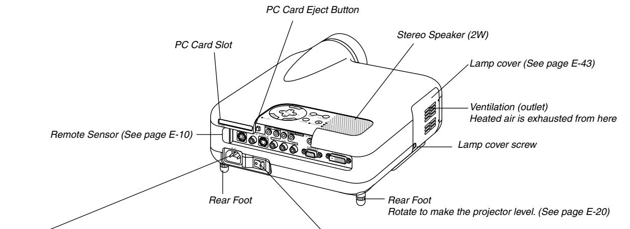
Terminal Panel Features
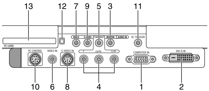
- COMPUTER IN / Component Input Connector (Mini D-Sub 15 Pin) Connect your computer or other analog RGB equipment such as IBM compatible or Macintosh computers. Use the supplied RGB cable to connect to your computer. This also serves as a component input connector that allows you to connect a component video output of component equipment such as a DVD player (optional adapter ADPCV1 required). This connector also supports SCART output signal. See page E-16 for more details.
- DVI-D IN (DVI 24 Pin) This connector can be used to accept digital signal output from a computer or a set top box with a DVI connector. (HDCP compatible)
- RGB/DVI AUDIO IN Mini Jack (Stereo Mini) This is where you connect audio output from your computer connected to RGB IN or DVI-D IN.
- COMPONENT (Y, Cb/Pb, Cr/Pr) input Connectors (RCA) Connect component video outputs (Y/Cb/Cr, Y/Pb/Pr) of the external equipment such as DVD player. NOTE: These connectors accept component signal only.
- COMPONENT AUDIO IN Mini Jack (Stereo Mini) This is where you connect audio output from your DVD player or component equipment connected to COMPONENT IN.
- VIDEO IN (RCA) Connect a VCR, DVD player or laser disc player here to project video.
7.VIDEO AUDIO IN Mini Jack (Stereo Mini) This is where you connect audio output from your VCR, DVD player or laser disc player connected to VIDEO IN. - S-VIDEO IN (Mini DIN 4 Pin) Connect a VCR, DVD player or laser disc player with S-Video output. NOTE: S-Video provides more vivid color and higher resolution than the traditional composite video format.
-
S-VIDEO AUDIO IN Mini Jack (Stereo Mini)
This is where you connect audio output from your VCR, DVD player or laser disc player connected to S-VIDEO IN. -
PC CONTROL Port (Mini DIN 8 Pin) Use this port to connect your PC to control your projector via a serial cable. This enables you to use your PC and serial communication protocol to control the projector. The NEC optional serial cable (CA03D) is required to use this port. If you are writing your own program, typical PC control codes are on page E-50. A cap is put on the port at the factory. Remove the cap when using the port.
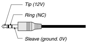
- SC TRIGGER Mini Jack
When the projector is powered ON the screen trigger output sends a high voltage trigger to the screen controller and the screen will go down.
When the projector is powered OFF the screen trigger stops sending a low voltage trigger to the screen controller and the screen will go up.
NOTE: To enable the SC.TRIGGER function, be sure to turn on "Screen Trigger" in "Page 1" of the Setup. See page E-33.
NOTE: Screen Controllers are supplied and supported by screen manufactures. This option is not included with the projector.
NOTE: Do not use this jack for anything other than intended use. Connecting an audio cable or equivalent to the SC. TRIGGER Mini Jack causes damage to this mini jack.
Stereo mini cable (not supplied)
- PC CARD Eject Button Press to eject a PC card partially.
- PC CARD Slot Insert a PC card or commercially available wired LAN card here.
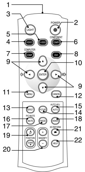
- Infrared Transmitter
Direct the remote control toward the remote sensor on the projector cabinet.
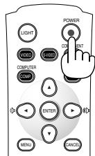
- POWER Button
Use this button to turn the power on and off when the main power is supplied and the projector is in standby mode (Power-saving mode or Idle mode).
To turn on or off the projector, press and hold this button for a minimum of two seconds.
- LIGHT Button
Use this button to turn on or off the button's backlight. Unless another button is pressed within 10 seconds while the backlight is on, it will turn off to conserve the batteries.
4.VIDEO Button
Press this button to select an NTSC, PAL, PAL-N, PAL-M, PAL60, SECAM or NTSC4.43 compatible video source from a VCR, DVD player, or laser disc player.
- S-VIDEO Button
Press this button to select an S-Video source from a VCR, DVD player or laser disc player.
- COMPONENT Button
Press this button to select a video source from component equipment connected to your COMPONENT input.
7.COMPUTER Button
Press this button to select a video source from computer or component equipment connected to your COMPUTER IN port.
- DVI Button
Press this button to select a DVI digital signal from a computer, DVD player or settop box.
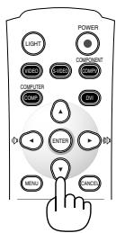
- Select ▲▼▲▶ / Volume Button
: Use these buttons to select the menu of the item you wish to adjust.
▲: Use these buttons to change the level of a selected menu item. When no menus appear, these buttons work as a volume control.
NOTE: When the Viewer is selected, volume control is not available.
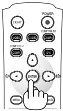
- ENTER Button
Executes your menu selection and activates items selected from the menu.
- MENU Button
Displays the menu for various settings and adjustments.
- CANCEL Button
Press this button to exit "Menu". Press this button to return the adjustments to the last condition while you are in the adjustment or setting menu.
- ASPECT Button
Press this button to display the Aspect Ratio select screen. Each time this button is pressed, the option will be changed. See page E-30.
- PICTURE Button
Press this button to display the Preset window. Each time this button is pressed, the option will be changed. See page E-29.
- AUTO ADJ Button
Use this button to adjust an COMPUTER source for an optimal picture. Some signals may not be displayed correctly or take time to be displayed. See page E-21.
NOTE: This function may not be available depending upon the input signal.
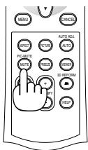
16.PIC-MUTEButton
This button turns off the image and sound for a short period of time. Press again to restore the image and sound.
NOTE: When the menu is displayed, a press of this button mutes an image and sound without turning off the menu.
- FREEZE Button
This button will freeze a picture. Press again to resume motion.
- VIEWER Button
Press this button to select the Viewer source.
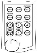
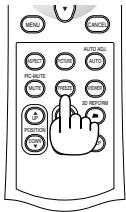
- POSITION Up/Down Button
This button adjusts position of a zoomed image. See page E-23.
- MAGNIFY (+) (-) Button
Use this button to adjust the image size up to 400% . The image is magnified about the center of the screen. When the image is magnified, you can move the image by using the SELECT button. See page E-24.
- 3D REFORM Button
Press this button to enter 3D Reform to correct the keystone (trapezoidal) distortion, and make the image square. See page E-20.
- HELP Button
Provides the online help or the set information.
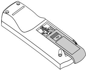
Battery Installation
- Press firmly and slide the battery cover off.
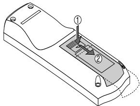
- Remove both old batteries and install new ones (AAA). Ensure that you have the batteries' polarity (+/-) aligned correctly.
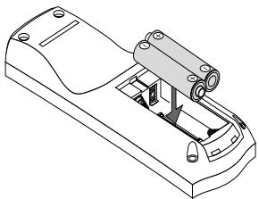
- Slip the cover back over the batteries until it snaps into place. Do not mix different types of batteries or new and old batteries.
Remote Control Precautions
- Handle the remote control carefully.
- If the remote control gets wet, wipe it dry immediately.
- Avoid excessive heat and humidity.
- If you will not be using the remote control for a long time, remove the batteries.
- Do not place the batteries upside down.
- Do not use new and old batteries together, or use different types of batteries together.
Operating Range
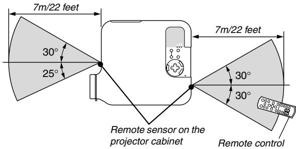
- The infrared signal operates by line-of-sight up to a distance of about 22 feet / 7 m and within a 55^ (Front) / 60^ (Rear) angle of the remote sensor on the projector cabinet.
- The projector will not respond if there are objects between the remote control and the sensor, or if strong light falls on the sensor. Weak batteries will also prevent the remote control from properly operating the projector.
INSTALLATION AND CONNECTIONS
This section describes how to set up your projector and how to connect video and audio sources.
Your projector is simple to set up and use. But before you get started, you must first:
1 Set up a screen and the projector.
2 Connect your video equipment to the projector. See page E-13 - 17.
3 Connect the supplied power cable. See page E-17.
NOTE: Ensure that the power cable and any other cables are disconnected before moving the projector. When moving the projector or when it is not in use, cover the lens with the lens cap.
Setting Up the Screen and the Projector
Selecting a Location
The further your projector is from the screen or wall, the larger the image. The minimum size the image can be is approximately 30^ (0.8 m) measured diagonally when the projector is roughly 4 feet (1.0 m) from the wall or screen. The largest the image can be is 200^ (5.08 m) when the projector is about 23 feet (7 m) from the wall or screen. Use the drawing below as a guide.
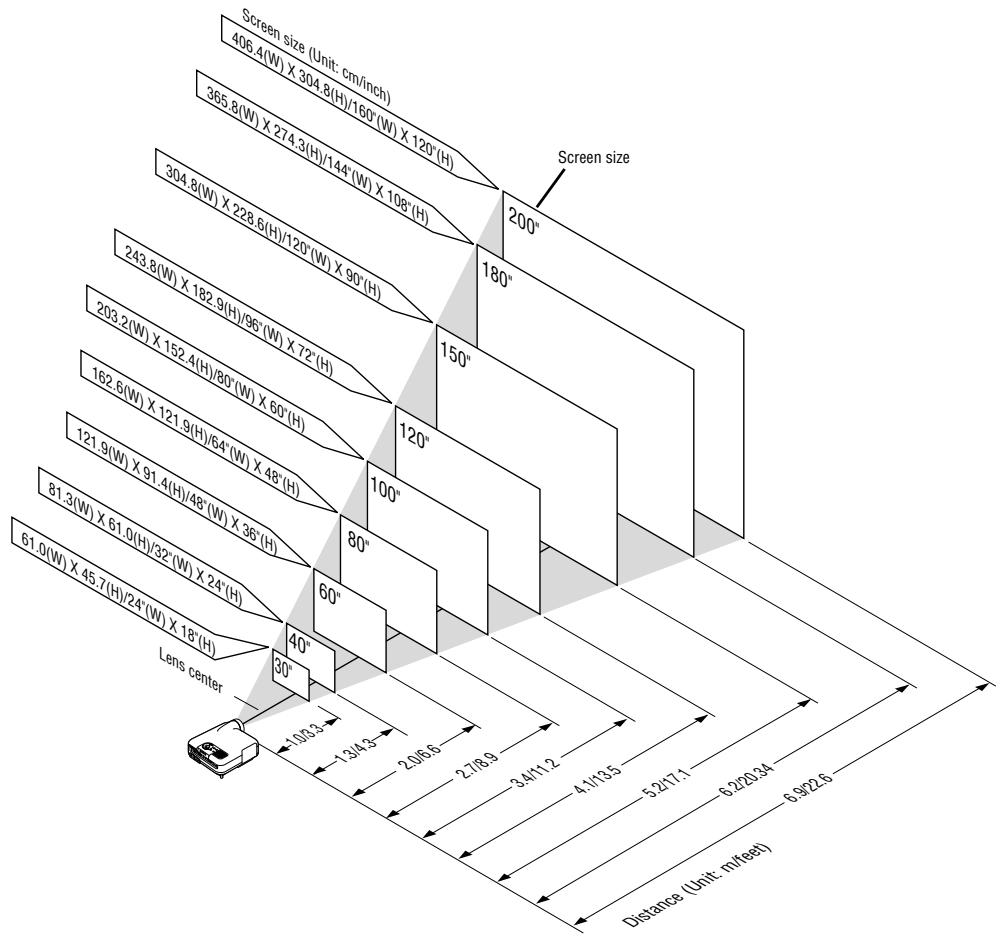
NOTE: The above shows the throw distance for 4:3 screen.
Throw Distance and Screen Size
The following shows the proper relative positions of the projector and screen. Refer to the table to determine the position of installation.
Distance Chart
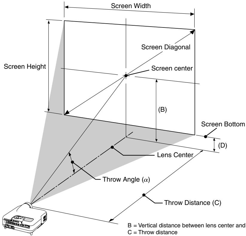
B = Vertical distance between lens center and screen center
C = Throw distance
D = Vertical distance between lens center and bottom of screen
= Throw angle
NOTE: Distances may vary +/-5%.
4:3
| Screen Size | B | C Wide – Tele | D | α Wide – Tele | ||
| Diagonal | Width | Height | ||||
| inch | inch | inch | inch | inch | inch | degree |
| 30 | 24 | 18 | 12.6 | 35.7 – 43.4 | 3.6 | 19.3 – 16.1 |
| 40 | 32 | 24 | 16.8 | 48.2 – 58.4 | 4.8 | 19.1 – 16.0 |
| 50 | 40 | 30 | 21.0 | 60.7 – 73.5 | 6.0 | 19.0 – 15.9 |
| 60 | 48 | 36 | 25.2 | 73.2 – 88.5 | 7.2 | 18.9 – 15.8 |
| 80 | 64 | 48 | 33.6 | 98.1 – 118.6 | 9.6 | 18.9 – 15.8 |
| 100 | 80 | 60 | 42.0 | 123.1 – 148.6 | 12.0 | 18.8 – 15.7 |
| 120 | 96 | 72 | 50.4 | 148.1 – 178.7 | 14.4 | 18.8 – 15.7 |
| 150 | 120 | 90 | 63.0 | 185.5 – 223.8 | 18.0 | 18.7 – 15.7 |
| 180 | 144 | 108 | 75.6 | 223.0 – 268.9 | 21.6 | 18.7 – 15.7 |
| 200 | 160 | 120 | 84.0 | 248.0 – 298.9 | 24.0 | 18.7 – 15.7 |
| Screen Size | B | C Wide – Tele | D | α Wide – Tele | ||
| Diagonal | Width | Height | ||||
| mm | mm | mm | mm | mm | mm | degree |
| 762.0 | 609.6 | 457.2 | 319.8 | 907 – 1102 | 91.2 | 19.3 – 16.1 |
| 1016.0 | 812.8 | 609.6 | 426.5 | 1224 – 1484 | 121.7 | 19.1 – 16.0 |
| 1270.0 | 1016.0 | 762.0 | 533.3 | 1541 – 1866 | 152.3 | 19.0 – 15.9 |
| 1524.0 | 1219.2 | 914.4 | 640.0 | 1858 – 2248 | 182.8 | 18.9 – 15.8 |
| 2032.0 | 1625.6 | 1219.2 | 853.4 | 2493 – 3011 | 243.8 | 18.9 – 15.8 |
| 2540.0 | 2032.0 | 1524.0 | 1066.9 | 3127 – 3775 | 304.9 | 18.8 – 15.7 |
| 3048.0 | 2438.4 | 1828.8 | 1280.4 | 3761 – 4539 | 366.0 | 18.8 – 15.7 |
| 3810.0 | 3048.0 | 2286.0 | 1600.6 | 4713 – 5684 | 457.6 | 18.7 – 15.7 |
| 4572.0 | 3657.6 | 2743.2 | 1920.8 | 5664 – 6829 | 549.2 | 18.7 – 15.7 |
| 5080.0 | 4064.0 | 3048.0 | 2134.3 | 6298 – 7593 | 610.3 | 18.7 – 15.7 |
NOTE: A 16:9 image is supported within the limits of the above values.
WARNING
- Installing your projector on the ceiling must be done by a qualified technician. Contact your NEC dealer for more information.
- Do not attempt to install the projector yourself.
- Only use your projector on a solid, level surface. If the projector falls to the ground, you can be injured and the projector severely damaged.
- Do not use the projector where temperatures vary greatly. The projector must be used at temperatures between 41^ ( 5^ ) and 95^ ( 35^ ).
- Do not expose the projector to moisture, dust, or smoke. This will harm the screen image.
- Ensure that you have adequate ventilation around your projector so heat can dissipate. Do not cover the vents on the side or the front of the projector.
Reflecting the Image
Using a mirror to reflect your projector's image enables you to enjoy a much larger image. Contact your NEC dealer if you need a mirror. If you're using a mirror and your image is inverted, use the MENU and SELECT buttons on your projector cabinet or buttons on your remote control to correct the orientation. (See page E-33.)
Making Connections
Wiring Diagram
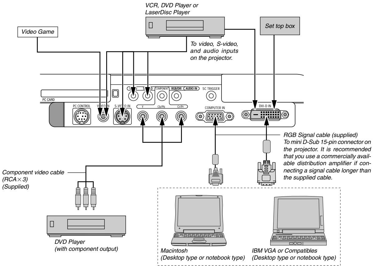
NOTE: When using with a notebook PC, be sure to connect between the projector and the notebook PC before turning on the power to the notebook PC. In most cases signal cannot be output from RGB output unless the notebook PC is turned on after connecting with the projector.
If the screen goes blank while using your remote control, it may be the result of the computer's screen-saver or power management software.
If you accidentally hit the POWER button on the remote control, wait 90 seconds and then press the POWER button again to resume.
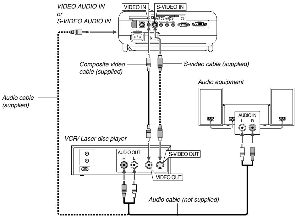
Use the supplied composite video cable to connect your VCR or laser disc player to your projector. To make these connections, simply:
- Turn off the power to the projector and VCR or laser disc player.
- Connect one end of the composite video cable to the video output connector on the back of your VCR or laser disc player, connect the other end to the Video input on your projector. Use an audio cable (not supplied) to connect the audio from your VCR or laser disc player to your audio equipment (if your VCR or laser disc player has this capability). Be careful to keep your right and left channel connections correct for stereo sound.
- Turn on the projector and the VCR or laser disc player.
NOTE: Refer to your VCR or laser disc player owner's manual for more information about your equipment's video output requirements.
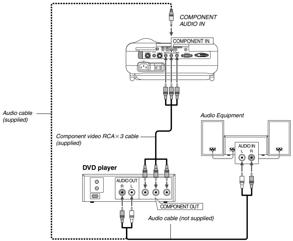
You can connect your projector to a DVD player with component output or Video output. To do so, simply:
- Turn off the power to your projector and DVD player.
- If your DVD player has the component video (Y,Cb,Cr) output, use the supplied component video cable (RCA× 3) to connect your DVD player to the COMPONENT IN connectors on the projector.
For a DVD player without component video (Y,Cb,Cr) output, use common RCA cables (not provided) to connect a composite Video output of the DVD player to the Video Input of the projector.
Use an audio cable (not supplied) to connect the audio from your VCR or laser disc player to your audio equipment (if your VCR or laser disc player has this capability). Be careful to keep your right and left channel connections correct for stereo sound. - Turn on the projector and DVD player.
NOTE: Refer to your DVD player's owner's manual for more information about your DVD player's video output requirements.
Connecting Your PC or Macintosh Computer
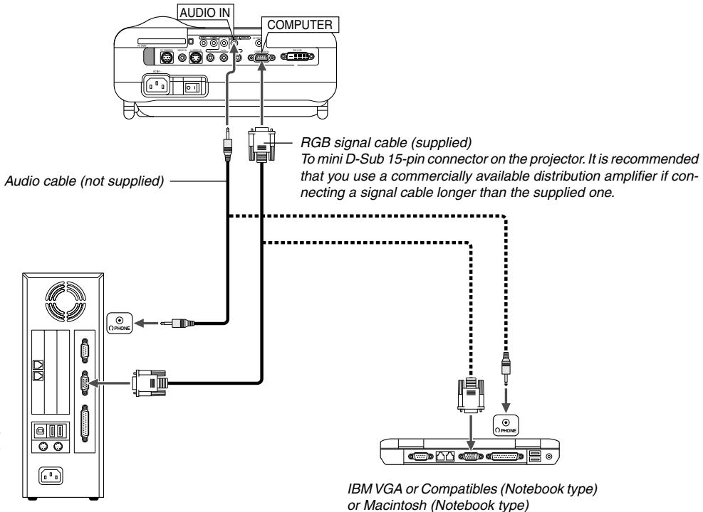
NOTE: For older Macintosh, use a commercially available pin adapter (not supplied) to connect to your Mac's video port.
IBM VGA or Compatible (Desktop type) or Macintosh (Desktop type)
Connecting your PC or Macintosh computer to your projector will enable you to project your computer's screen image for an impressive presentation.
To connect to a PC or Macintosh, simply:
- Turn off the power to your projector and computer.
- Use the supplied signal cable to connect your PC or Macintosh to the projector.
- Turn on the projector and the computer.
- If the projector goes blank after a period of inactivity, it may be caused by a screen saver installed on the computer you've connected to the projector.
NOTE: The HT100 is not compatible with video decoded outputs of NEC ISS-6020 and ISS-6010.
NOTE: An image may not be displayed correctly when a Video or S-Video source is played back via a commercially available scan converter. This is because the projector will process a video signal as a computer signal at the default setting. In that case, do the following.
- When noise appears on the sides of the screen: Use the Overscan feature to display the image correctly. Be sure to change the Overscan to 0% before pressing the AUTO ADJ or AUTO ADJUST button. Unless otherwise an image may be displayed with its sides cut off.
For European model only
To connect SCART output (RGB)
Before connections: The supplied SCART adapter (ADP-SC1) and a commercially available SCART cable are required for this connection.
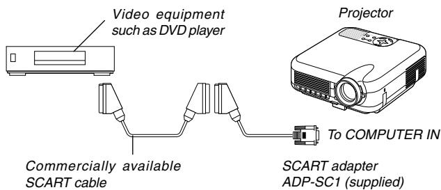
NOTE: Audio signal is not available for this connection.
- Turn off the power to the projector and your video equipment.
- Use the supplied SCART adapter and a commercially available SCART cable to connect the COMPUTER input of your projector and a SCART output (COMPUTER) of your video equipment.
- Turn on the power to the projector and your video equipment.
- Use the COMPUTER button on the remote control to select the COMPUTER input.
- Press the MENU button on the remote control to display the menu.
- From the Advanced menu, select [Setup] [Page 2] [Signal Select] [Computer] [Scart]. SCART is a standard European audio-visual connector for TVs, VCRs and DVD players. It is also referred to as Euro-connector.
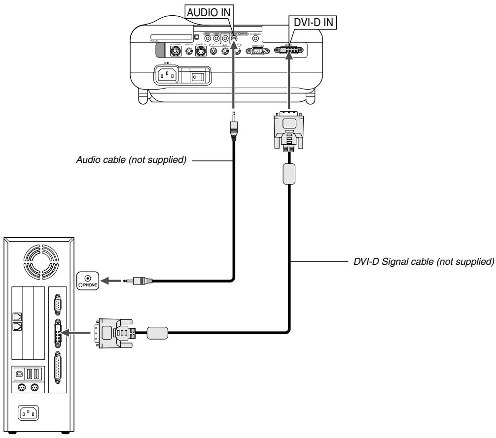
To project a DVI digital signal, be sure to connect the PC and the projector using a DVI-D signal cable (not supplied) before turning on your PC or projector. Turn on the projector first and select DVI (DIGITAL) from the source menu before turning on your PC.
Failure to do so may not activate the digital output of the graphics card resulting in no picture being displayed. Should this happen, restart your PC. Do not disconnect the DVI-D signal cable while the projector is running. If the signal cable has been disconnected and then re-connected, an image may not be correctly displayed. Should this happen, restart your PC.
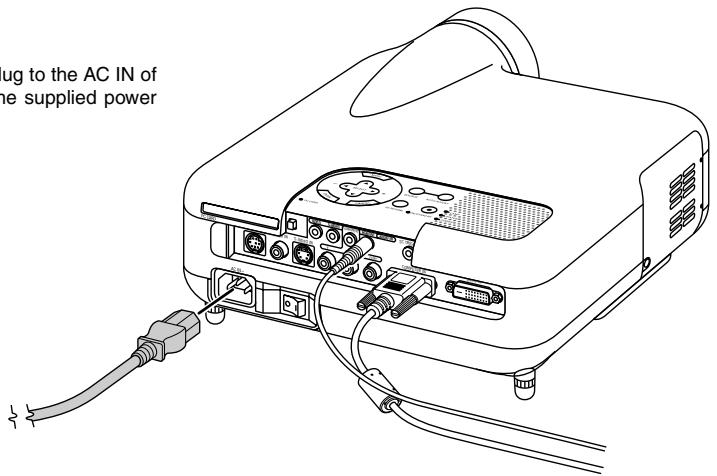
Connecting the Supplied Power Cable
Connect the supplied power cable to the projector.
First connect the supplied power cable's three-pin plug to the AC IN of the projector, and then connect the other plug of the supplied power cable in the wall outlet.
NOTE:
- Use the DVI-D cable compliant with DDWG (Digital Display Working Group) DVI (Digital Visual Interface) revision 1.0 standard. The DVI-D cable should be within 5m (196') long.
See page E-49 for DVI digital signals the DVI (DIGITAL) connector supports.
PROJECTING AN IMAGE (BASIC OPERATION)
This section describes how to turn on the projector and to project a picture onto the screen.
Turning on the Projector
NOTE:
- When plugging in or unplugging the supplied power cable, make sure that the main power switch is pushed to the off[0] position. Failure to do so may cause damage to the projector.
- The projector has two power switches: main power switch and POWER button.
- The projector has a feature to prevent itself from being used by unauthorized individuals. To use this feature, register your PC card as a protect key. See "Security" on page E-36 for more details.
To turn on the main power to the projector, press the Main Power switch to the ON position (1).
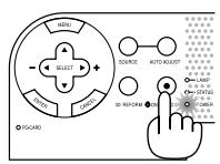
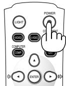
Before you turn on your projector, ensure that the computer or video source is turned on and that your lens cap is removed.
Only after you press the POWER (ON/STAND BY) button on the projector cabinet or POWER button on the remote control for a minimum of 2 seconds will the power indicator turn to green and the projector become ready to use.
Note on Startup screen (Menu Language Select screen)
When you first turn on the projector, you will get the Startup screen. This screen gives you the opportunity to select one of the 18 menu languages.
- Use the SELECT or button to select one of the 18 languages for the menu.
Menu Language Select
Please select a menu language.
- Press the ENTER button to execute the selection.
- The menu will be displayed in the language you have selected.

To close the menu, press the CANCEL button.
After this has been done, you can proceed to the menu operation. If you want, you can select the menu language later. See "Language" on page E-33.
When the Lamp mode is set to Eco, the Lamp indicator will light green. If one of the following things happens, the projector will not turn on.
- If the internal temperature of the projector is too high, the projector detects abnormal high temperature. In this condition the projector will not turn on to protect the internal system. If this happens, wait for the projector's internal components to cool down.
- When the lamp reaches its end of usable life, the projector will not turn on. If this happens, replace the lamp.
- If the lamp fails to light, and if the STATUS indicator flashes on and off in a cycle of six times, wait a full minute and then turn on the power.
Selecting a Source
Selecting the computer or video source
Using the Remote Control
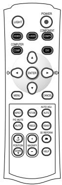
Press any one of the VIDEO, S-VIDEO, COMPONENT, COMPUTER, DVI or VIEWER buttons.
NOTE: If no input signal is available, the projector will display a blue background (factory preset).
Selecting from Source List
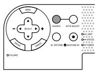
Source List
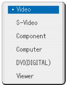
Press and quickly release the SOURCE button on the projector cabinet to display the Source list. Each time the SOURCE button is pressed, the input source will change as follows: "Video" (VCR, or laser disc player), S-Video", "Component" (DVD player), "Computer" or "DVI(DIGITAL)" (computer) or "Viewer" (slides on a PC card). To display the selected source, press the ENTER button.
Detecting the Signal Automatically
Press and hold the SOURCE button for a minimum of 1 second, the projector will search for the next available input source. Each time you press and hold the SOURCE button, the input source will change as follows:
Video S-Video Component Computer DVI(DIGITAL) Viewer
If no input signal is present, the input will be skipped. When the input source you wish to project is displayed, release the button.
Adjusting the Picture Size and Position
Place your projector on a flat level surface and ensure that the projector is square to the screen.
Lift the front edge of the projector to center the image vertically.
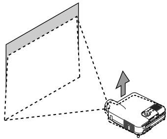
Move the projector left to center the image horizontally on the screen.
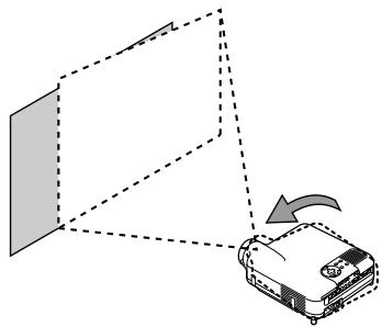
- If the projected image does not appear square to the screen then use the 3D Reform feature for proper adjustment. See page E-20.
Adjust the Tilt Foot
- Lift the front edge of the projector.
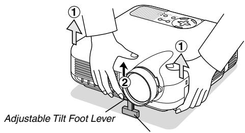
Adjustable Tilt Foot
- Push up the Adjustable Tilt Foot Lever on the front of the projector to extend the adjustable tilt foot (maximum height).
- Push down the Adjustable Tilt Foot Lever.
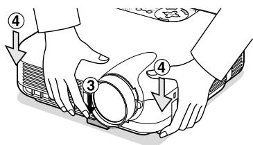
- Lower the front of the projector to the desired height and release the Adjustable Tilt Foot Lever to lock the Adjustable tilt foot. There is approximately 7 degrees of up and down adjustment for the front of the projector.
Adjusting Screen Position
See "Selecting Aspect Ratio and Position for Screen" on page E-33.
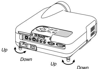
The rear foot height can be changed. Rotate the rear foot to the desired height, but the vertical distance from the bottom to the desk or floor should be 1'' (25 mm) to make the projector horizontal on the flat surface.
CAUTION:
Do not use the tilt-foot for purposes other than originally intended. Misuses such as gripping the tilt-foot or hanging on the wall can cause damage to the projector.
Zoom
Use the Zoom lever to fine adjust the image size on the screen.
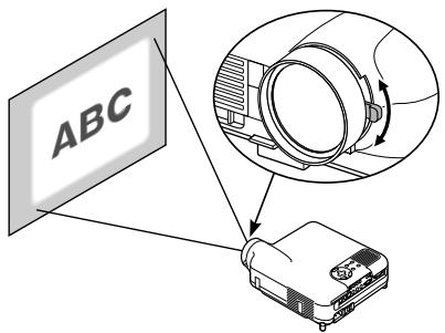
Focus
Use the Focus ring to obtain the best focus.
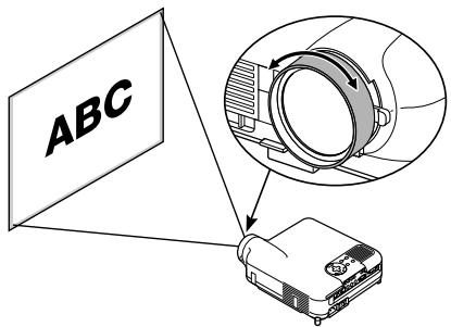
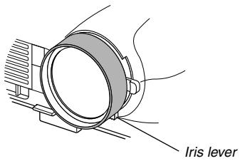
Iris
Use the Iris lever underneath the lens to adjust the brightness and the contrast ratio optically.
Correcting the Horizontal and Vertical Keystone Distortion (3D Reform)
Use the 3D Reform feature to correct keystone (trapezoidal) distortion to make the top or bottom and the left or right side of the screen longer or shorter so that the projected image is rectangular.
Two options are available for correcting procedures.
Press the 3D REFORM button to toggle between Keystone and Cornerstone.
Keystone
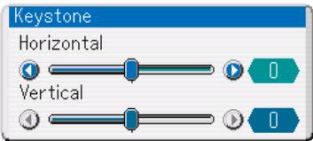
- Press the SELECT button to adjust the horizontal keystone.
- Press the SELECT button to select "Vertical".
- Press the SELECT button to adjust the vertical keystone.
- After completing, press the ENTER button.
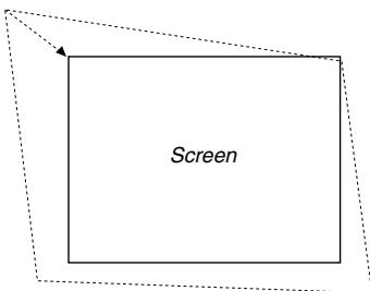
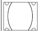
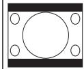
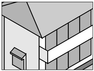
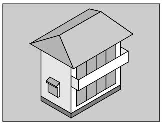
Cornerstone
- Project an image so that the screen is smaller than the area of the raster.
- Pick up any one of the corners and align the corner of the screen with the one of the image.
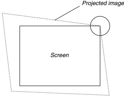
(The drawing shows the upper right corner.)
- Press the 3D REFORM button on the remote control.
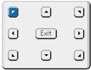
The Cornerstone adjustment screen is displayed.
NOTE: Press the 3D REFORM button to toggle between "Cornerstone" and "Keystone."
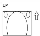
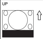
- Use the SELECT button to select one icon which points in the direction you wish to move the projected image frame.
- Press the ENTER button.
- Use the SELECT button to move the projected image frame as shown on the example.
- Press the ENTER button.
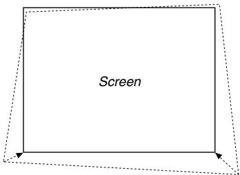
- Use the SELECT button to select another icon which points in the direction.
On the Cornerstone adjustment screen, select "Exit" or press the CANCEL button on the remote control.
The confirmation screen is displayed.
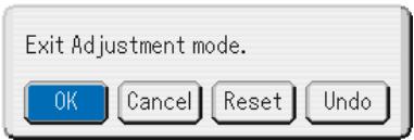
- Press the SELECT or button to highlight the [OK] and press the ENTER button.
This completes the keystone correction.
Selecting "Cancel" will return to the adjustment screen without saving changes (Step 3).
Selecting "Reset" will return to the factory default.
Selecting "Undo" will exit without saving changes.
NOTE: To return the 3D Reform correction setting values to the factory default, press and hold the 3D REFORM button for a minimum of 2 seconds.
NOTE: During 3D Reform adjustment, "Aspect Ratio" and "Screen" may not be available. Should this happen, first reset the 3D Reform data and then do each setting. Second repeat the 3D Reform adjustment. Changing Aspect Ratio and/ or Screen setting can limit 3D Reform in its adjustable range.
The adjustable ranges for 3D Reform are as follows:
Horizontal Max ± 25^ approx. Vertical Max ± 40^ approx.
- The following are conditions at the above maximum angle when all of the following are met
- Image is projected in Wide (Zoom lever)
- Resolution is XGA
Higher resolution than XGA limits 3D Reform in its adjustable range.
- Menu items should be set as follows:
Aspect Ratio . Normal
Screen Type 4:3
Horizontal and Vertical are adjusted separately.
A combination of both adjustments limits 3D Reform in its adjustable range.
- When "Stadium" is selected in Aspect Ratio, "Cornerstone" and "Horizontal Keystone" are not available except Video, S-Video, 480p and 576p signals.
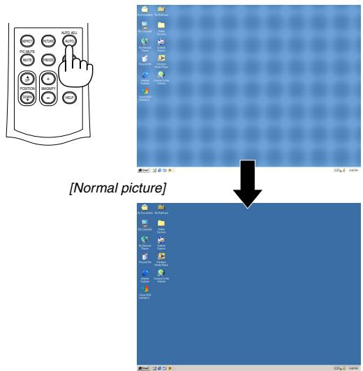
Optimizing RGB Picture Automatically
Adjusting the Image Using Auto Adjust
Optimizing RGB image automatically
Press the Auto Adjust button to optimize an RGB image automatically.
[Poor picture]
Press the Auto Adjust button to fine-tune the computer image or to remove any vertical banding that might appear and to reduce video noise, dot interference or cross talk (this is evident when part of your image appears to be shimmering). This function adjusts the clock frequencies that eliminate the horizontal banding in the image. This function also adjusts the clock phase to reduce video noise, dot interference or cross talk. (This is evident when part of your image appears to be shimmering.)
This adjustment may be necessary when you connect your computer for the first time.
NOTE:
- Some signals may not be displayed correctly or take time.
- The Auto Adjust function does not work for component and video signals and some RGB signals such as 1080i, 1080p and 720p.
- If the Auto Adjust operation cannot optimize the RGB signal, try to adjust Clock and Phase manually. See page E-32.
Turning Up or Down Volume
Sound level from the speaker on the projector can be adjusted when the menu is not displayed.
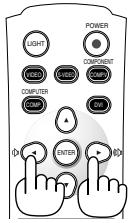
decrease volume
increase volume
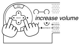
decrease volume

Volume bar
Turning off the Projector
To turn off the projector:
First press the POWER (ON/STAND BY) button on the projector cabinet or the POWER button on the remote control for a minimum of two seconds.
The power indicator will glow orange. After the projector turns off, the cooling fans keep operating for 90 seconds (Cooling-off time).
Second, turn off the Main Power switch. The power indicator will go out. Last unplug the power cable.
CAUTION
-
Do not unplug the power cable from the wall outlet or do not turn off the main power under any one of the following circumstances. Doing so can cause damage to the projector:
-
While the Hour Glass icon appears.
- While the message "Please wait a moment." appears. This message will be displayed after the projector is turned off.
- While the cooling fans are running. (The cooling fans continue to work for 90 seconds after the projector is turned off).
- While accessing a PC card. (The PC Card Access indicator lights.)
CONVENIENT FEATURES
Using Image Position
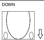
The POSITION button adjusts the position of an image when "Zoom", "V-Zoom" or "Cinema" is selected in Aspect Ratio.
See also "Adjusting the position of an image [Image Position]" on page E-32.
When "4:3" is selected in Screen Type:
Move the viewable area up or down
Zoom or V-Zoom
Move the position of an image up or down
Cinema
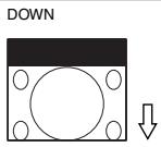
When "16:9" and "Anamorphic"(*) are selected in Screen Type:
Move the viewable area up or down
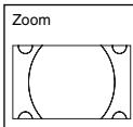
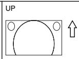
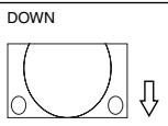
Table of Availability for Image Position
For PC, DVD Progressive, 480p, 480i, 576p, 576i
| Screen Type | Aspect Ratio | |||||
| Normal | Full | Zoom | Cinema | V-Zoom | Stadium | |
| 4:3 | Not available | Available | Available | Available | ||
| 16:9 Anamorphic* | Not available | Not available | Available | Not available | ||
For 720p, 1080i, 1080p
| Screen Type | Aspect Ratio | |||||
| Normal | Full | Zoom | Cinema | V-Zoom | Stadium | |
| 4:3 | Available | Not available | Available | Not available | ||
| 16:9 Anamorphic* | Not available | |||||
- A commercially available anamorphic lens is needed.
Turning Off the Image and Sound
Press the PIC MUTE button to turn off the image and sound for a short period of time. Press again to restore the image and sound.
Freezing a Picture
Press the FREEZE button to freeze a picture. Press again to resume motion.
Capturing a Picture
You can capture a still image while freezing it.
- Press the FREEZE button and then press the MENU button. The CAPTURE window will be displayed.
- Press the ENTER button to capture the image.
NOTE: A “CAP_” folder will be created and a captured image will be stored in the PC card inserted into the projector's slot.
- Select "Exit" or press the CANCEL button to end the CAPTURE screen.
NOTE: To delete captured images, see "Deleting Captured Images" on page E-41.
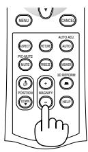
Enlarging and Moving a Picture
You can enlarge the area you want up to 400 percent.
To do so:
To enlarge the image:
- Press the MAGNIFY (+) button.
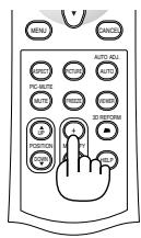
- Press the MAGNIFY(-) button to return to its original size.
To enlarge the image:
Use the SELECT button to move the enlarged portion.
NOTE: The FREEZE button does not work when an image is magnified.
Getting the On-line Help
You get the contents about Help.
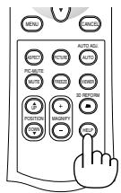
Display Help
Exit Help
Using the Menus
- Press the MENU button on the remote control or the projector cabinet to display the menu.
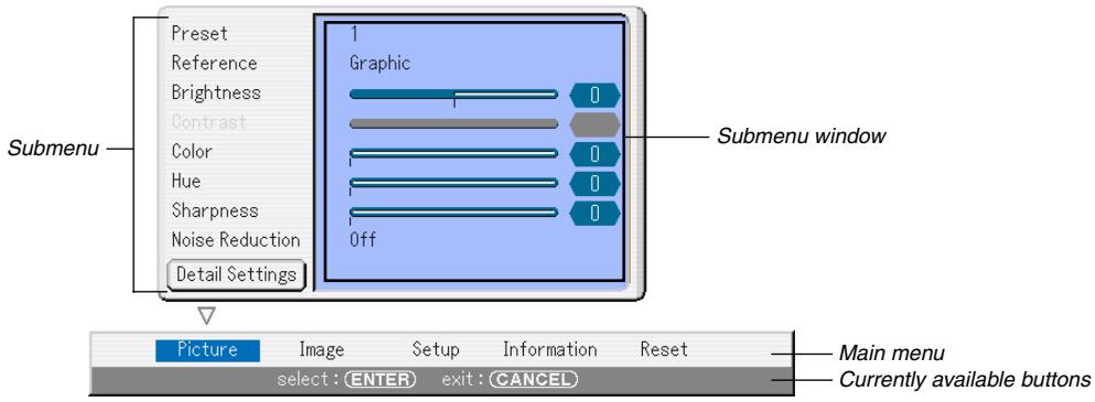
The Picture menu will be displayed (factory preset).
NOTE: The commands such as , ENTER, CANCEL in the gray bar show available buttons for your operation.
- Press the SELECT buttons on the remote control the projector cabinet to display the submenu.
- Press the ENTER button on the remote control or the projector cabinet to highlight the top item or the first tab.
- Use the SELECT buttons on the remote control or the projector cabinet to select the item you want to adjust or set. You can use the SELECT buttons on the remote control or the projector cabinet to select the tab you want. NOTE: You can select a tab only when the tab color is blue.
- Press the ENTER button on the remote control or the projector cabinet to display the menu window. NOTE: You can also display a menu window by pressing the SELECT button.
- Adjust the level or turn the selected item on or off by using the SELECT buttons on the remote control or the projector cabinet.
- Press the ENTER button or the CANCEL button on the remote control or the projector cabinet. Changes are stored until you adjust it again.
ENTER ....... Stores changes.
CANCEL ....... Returns to the previous screen without storing changes.
- Repeat steps 2 -7 to adjust an additional item, or press the CANCEL button on the remote control or the projector cabinet to quit the menu display.
Menu tree
| Main menu | Submenu | Items | ||
| Picture | Preset | 1 to 5 | ||
| Reference | Video, Movie, Game, sRGB, Graphic | |||
| Brightness | ||||
| Contrast | ||||
| Color | ||||
| Hue | ||||
| Sharpness | ||||
| Noise Reduction | Off, Low, Medium, High | |||
| Detail Settings | Page 1 | Gamma Correction | Dynamic, Natural, Black Detail | |
| Color Temperature | 5000, 5400, 6000, 6500, 7000, 7800, 8500, 9300, 10500 | |||
| Page 2 | Brightness R | |||
| Brightness G | ||||
| Brightness B | ||||
| Contrast R | ||||
| Contrast G | ||||
| Contrast B | ||||
| Page 3 | Red | |||
| Green | ||||
| Blue | ||||
| Yellow | ||||
| Magenta | ||||
| Cyan | ||||
| Color Gain | ||||
| Page 4 | SweetVision Mode | Off, On, Split | ||
| SweetVision Level | 0 to 63 | |||
| 3D Y/C Separation | Off, On | |||
| Deinterlace | Off, On | |||
| Telecine | Off, Auto | |||
| Black Expansion | Off, 1, 2, 3, 4, 5 | |||
| Contrast Enhancement | -3, -2, -1, Off, 1, 2, 3 | |||
| Image | Page 1 | Aspect Ratio(4:3) | Normal, Zoom, Cinema, V-Zoom | |
| (16:9, Anamorphic) | Normal, Full, Zoom, Stadium | |||
| Blanking | Top, Bottom, Left, Right | |||
| Position / Clock | Horizontal, Vertical, Clock, Phase | |||
| Image Position | -64 to 64 | |||
| Overscan | 0%, 5%, 10% | |||
| Signal Type | RGB, Component | |||
| Setup Level | Off, On | |||
| Video Filter | Off, Less, More | |||
| Page 2 | Entry List | |||
| Setup | Page 1 | Screen | Screen Type | 4:3, 16:9, Anamorphic |
| Position | -64 to 64 | |||
| Orientation | Desktop Front, Ceiling Rear, Desktop Rear, Ceiling Front | |||
| Lamp Mode | Normal, Eco | |||
| Screen Trigger | Off, On | |||
| Background | Blue, Black, Logo | |||
| Language | English, Deutsch, Français, Italiano, Espanol, Svenska, Suomi, Norsk, Nederlands, Türkıce, Polski, Руск CNC, Демлар, Рту guões,check, 日本語, 한국어, 中文 | |||
| Test Pattern | ||||
| Page 2 | Signal Select | Computer | RGB/Component, RGB, Component, Scart | |
| Video | Auto, NTSC3.58, NTSC4.43, PAL, PAL-M, PAL-N, PAL60,SECAM | |||
| S-Video | Auto, NTSC3.58, NTSC4.43, PAL, PAL-M, PAL-N, PAL60,SECAM | |||
| Standby Mode | Idle Mode, Power-saving Mode | |||
| Fan Mode | Auto, High Speed | |||
| Lamp Hour | Clear Lamp Hour Meter | |||
| Auto Adjust | Off, Normal, Fine | |||
| Page 3 | Password (Logo) | Entry, Delete | ||
| LAN Mode | IP Address | Automatic, Manual IP Address Subnet Mask Projector Name Gateway DNS Configuration Domain Name | ||
| DHCP | Host Name Option Client-Identifier Option | |||
| Alert Mail Sender's Address SMTP Server Name Recipient's Address 1 Recipient's Address 2 Recipient's Address 3 Test Mail | ||||
| Status | IP Address, Subnet Mask, Gateway, Mac Address, Reconnect | |||
| Security | Enable, Disable Keyword Use Protectkey, Read, Register, Delete | |||
| Information | Page 1 | Source Name, Input Terminal, Entry No., Horizontal Frequency, Vertical Frequency | ||
| Page 2 | Signal Type, Video Type, Sync Type, Interlace, Sync Polarity | |||
| Page 3 | Remaining Lamp Time, Lamp Hour Meter, Projector Usage | |||
| Page 4 | Version (BIOS, Firmware, Data) | |||
| Reset | Current Signal, All Data, All Data (Including Entry List) | |||