
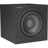
B&W ASW 3000 - Subwoofer B&W - Free user manual and instructions
Find the device manual for free B&W ASW 3000 B&W in PDF.
| Brand | B&W |
| Model | ASW 3000 |
| Type | Active subwoofer |
| Magnetic shielding | Yes, compatible with TV proximity |
| Input connections | Line inputs (RCA) and speaker inputs (4 mm terminals) |
| Low-pass filter | Adjustable (crossover frequency) |
| Available adjustments | Volume, crossover frequency, phase (0° / 180°) |
| Automatic standby | Yes, after 5 minutes without signal |
| Operating indicator | Red LED (standby) / green LED (active) |
| Included accessories | 4 decoupling spikes, 4 self-adhesive pads |
| Recommended use | Home cinema and high-fidelity stereo |
| Recommended placement | Near satellites, avoid corners unless adjustment made |
| Safety instructions | Do not expose to moisture, do not open, use identical fuses |
| Maintenance | Soft dry cloth, clean the grille with a soft brush |
| Cooling | Finned heatsink, requires adequate ventilation |
| THX compatibility | Usable with a THX controller (not THX certified) |
| Power supply | Mains, voltage varies by country (check device) |
Frequently Asked Questions - B&W ASW 3000 B&W
User questions about B&W ASW 3000 B&W
0 question about this device. Answer the ones you know or ask your own.
Ask a new question about this device
Download the instructions for your Subwoofer in PDF format for free! Find your manual B&W ASW 3000 - B&W and take your electronic device back in hand. On this page are published all the documents necessary for the use of your device. B&W ASW 3000 by B&W.
USER MANUAL B&W ASW 3000 B&W
ASW™ 3000 Owner's manual
English 5
Francais. 8
Deutsch. 11
Espanol 14
Portugues 17
Italiano 20
Nederlands 23
Elambdaiká 26
中文 29
Magyar 32
Polski 35
Pycckn 38
Dansk. 42
Svenska 42
Norsk. 42
Suomi. 43
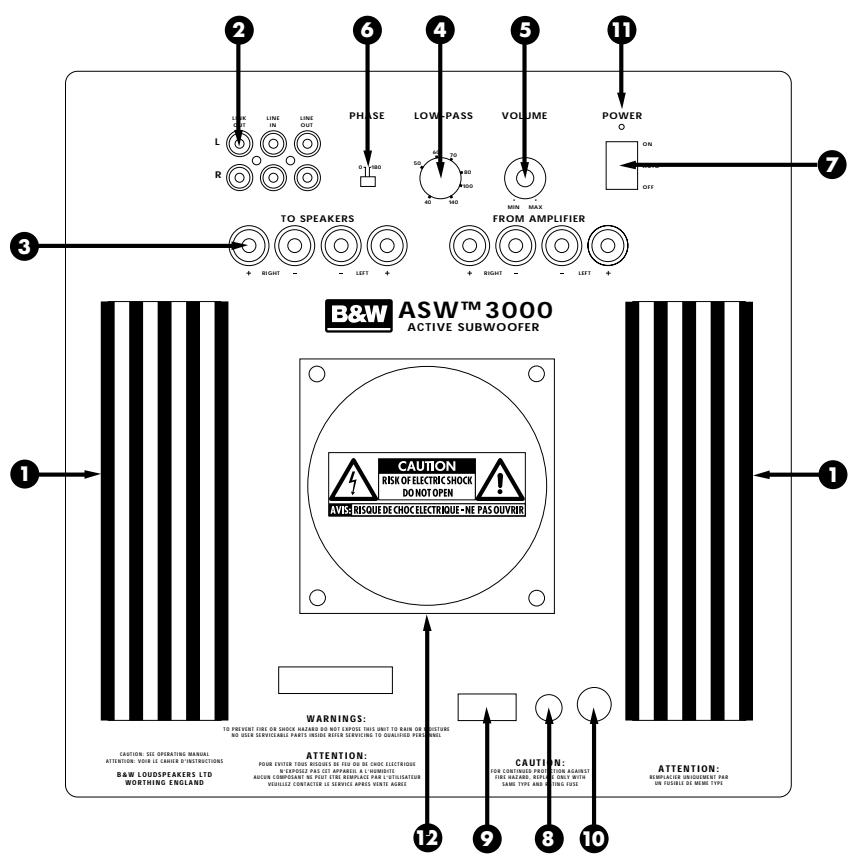
Figure 2
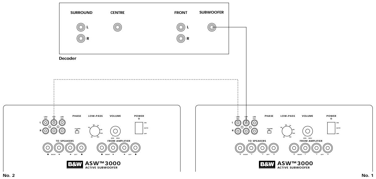
Figure 3
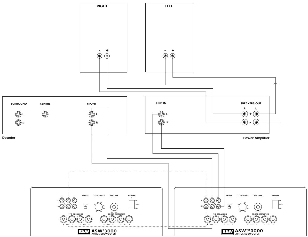
Figure 4
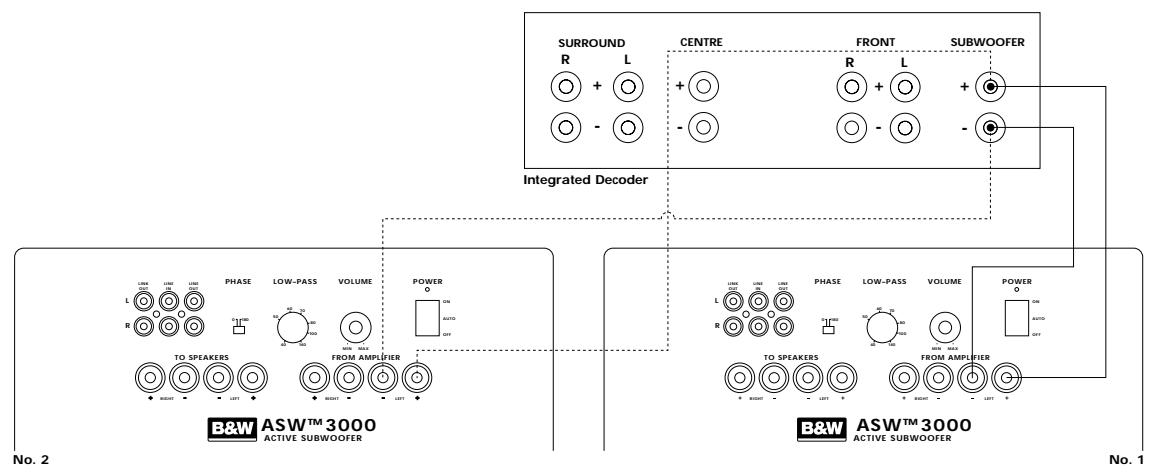
Figure 5
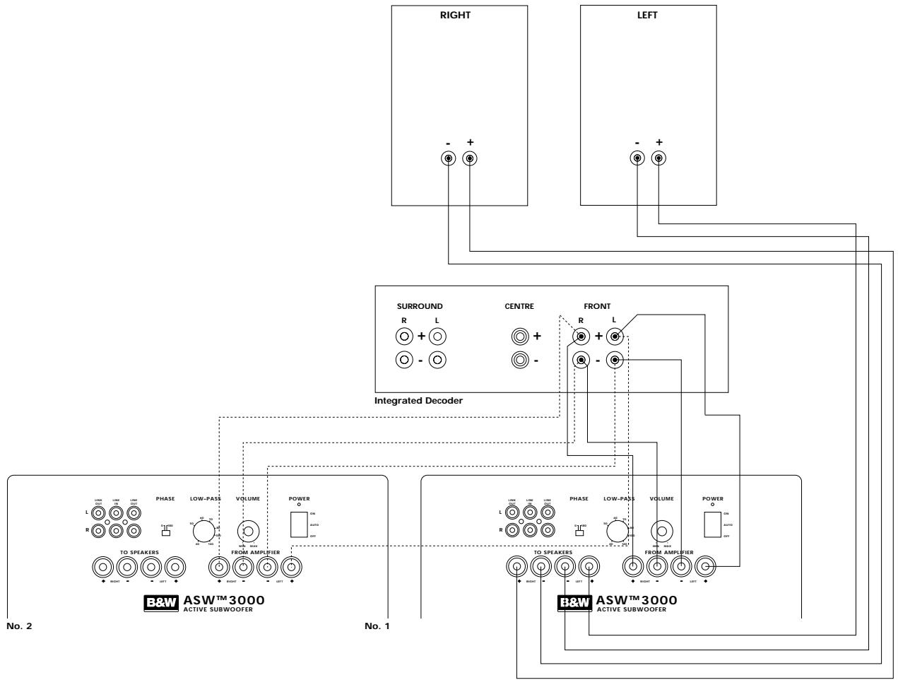
Figure 6
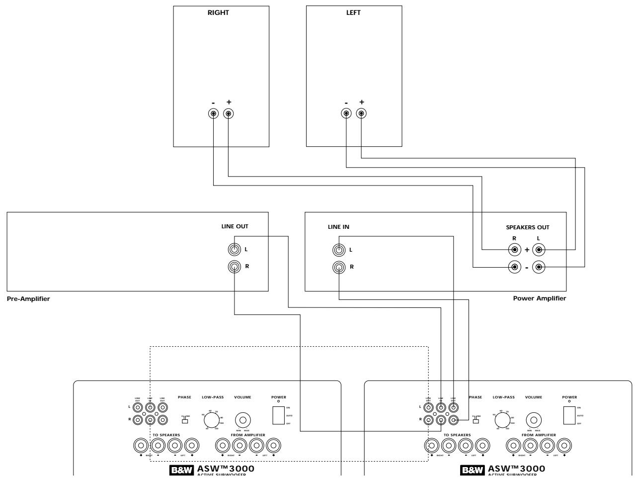
Figure 7
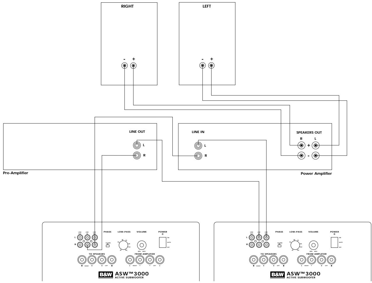
Figure 8
No. 2
Figure 9
Figure 10
No. 2
No.1
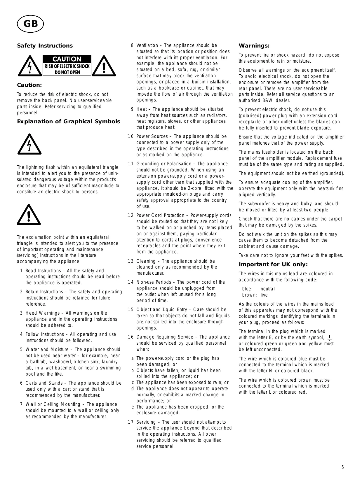
Safety Instructions
CAUTION
RISK OF ELECTRIC SHOCK DO NOT OPEN

Caution:
To reduce the risk of electric shock, do not remove the back panel. No user-serviceable parts inside. Refer servicing to qualified personnel.
Explanation of Graphical Symbols
The lightning flash within an equilateral triangle is intended to alert you to the presence of uninsulated dangerous voltage within the product's enclosure that may be of sufficient magnitude to constitute an electric shock to persons.

The exclamation point within an equilateral triangle is intended to alert you to the presence of important operating and maintenance (servicing) instructions in the literature accompanying the appliance
1 Read Instructions - All the safety and operating instructions should be read before the appliance is operated.
2 Retain Instructions - The safety and operating instructions should be retained for future reference.
3 HeedWarnings - All warnings on the appliance and in the operating instructions should be adhered to.
4 Follow Instructions - All operating and use instructions should be followed.
5 Water and Moisture - The appliance should not be used near water - for example, near a bathtub, washbowl, kitchen sink, laundry tub, in a wet basement, or near a swimming pool and the like.
6 Carts and Stands - The appliance should be used only with a cart or stand that is recommended by the manufacturer.
7 Wall or Ceiling Mounting - The appliance should be mounted to a wall or ceiling only as recommended by the manufacturer.
8 Ventilation - The appliance should be situated so that its location or position does not interfere with its proper ventilation. For example, the appliance should not be situated on a bed, sofa, rug, or similar surface that may block the ventilation openings, or placed in a built-in installation, such as a bookcase or cabinet, that may impede the flow of air through the ventilation openings.
9 Heat - The appliance should be situated away from heat sources such as radiators, heat registers, stoves, or other appliances that produce heat.
10 Power Sources - The appliance should be connected to a power supply only of the type described in the operating instructions or as marked on the appliance.
11 Grounding or Polarisation - The appliance should not be grounded. When using an extension power-supply cord or a power-supply cord other than that supplied with the appliance, it should be 2-core, fitted with the appropriate moulded-on plugs and carry safety approval appropriate to the country of use.
12 Power Cord Protection - Power-supply cords should be routed so that they are not likely to be walked on or pinched by items placed on or against them, paying particular attention to cords at plugs, convenience receptacles and the point where they exit from the appliance.
13 Cleaning - The appliance should be cleaned only as recommended by the manufacturer.
14 Non-use Periods - The power cord of the appliance should be unplugged from the outlet when left unused for a long period of time.
15 Object and Liquid Entry - Care should be taken so that objects do not fall and liquids are not spilled into the enclosure through openings.
16 Damage Requiring Service - The appliance should be serviced by qualified personnel when:
a The power-supply cord or the plug has been damaged; or
b Objects have fallen, or liquid has been spilled into the appliance; or
c The appliance has been exposed to rain; or
d The appliance does not appear to operate normally, or exhibits a marked change in performance; or
e The appliance has been dropped, or the enclosure damaged.
17 Servicing - The user should not attempt to service the appliance beyond that described in the operating instructions. All other servicing should be referred to qualified service personnel.
Warnings:
To prevent fire or shock hazard, do not expose this equipment to rain or moisture.
Observe all warnings on the equipment itself. To avoid electrical shock, do not open the enclosure or remove the amplifier from the rear panel. There are no user serviceable parts inside. Refer all service questions to an authorised B&W dealer.
To prevent electric shock, do not use this (polarised) power plug with an extension cord receptacle or other outlet unless the blades can be fully inserted to prevent blade exposure.
Ensure that the voltage indicated on the amplifier panel matches that of the power supply.
The mains fuseholder is located on the back panel of the amplifier module. Replacement fuse must be of the same type and rating as supplied.
The equipment should not be earthed (grounded).
To ensure adequate cooling of the amplifier, operate the equipment only with the heatsink fins aligned vertically.
The subwoofer is heavy and bulky, and should be moved or lifted by at least two people.
Check that there are no cables under the carpet that may be damaged by the spikes.
Do not walk the unit on the spikes as this may cause them to become detached from the cabinet and cause damage.
Take care not to ignore your feet with the spikes.
Important for UK only:
The wires in this mains lead are coloured in accordance with the following code:
blue: neutral
brown: live
As the colours of the wires in the mains lead of this apparatus may not correspond with the coloured markings identifying the terminals in your plug, proceed as follows:
The terminal in the plug which is marked with the letter E, or by the earth symbol, 1一 or coloured green or green and yellow must be left unconnected.
The wire which is coloured blue must be connected to the terminal which is marked with the letter N or coloured black.
The wire which is coloured brown must be connected to the terminal which is marked with the letter L or coloured red.
Introduction
Thank you for purchasing the B&W ASW™3000 Active Subwoofer.
Since its foundation in 1966, the continuing philosophy of B&W has been the quest for perfect sound reproduction. Inspired by the company's founder, the late John Bowers, this quest has entailed not only high investment in audio technology and innovation but also an abiding appreciation of music and the demands of film sound to ensure that the technology is put to maximum effect.
The ASW™ 3000 has been designed for Home Theatre installations and to augment the bass performance of 'full range' speakers in stereo audio use. Adding the subwoofer to your system not only extends the bass to lower frequencies, it improves the midrange clarity by reducing the low-frequency demands on your existing speakers.
The subwoofer is magnetically shielded for use close to a television screen.
Please read through this manual fully before using the subwoofer. All sound installations require some planning and experimentation if you are to get the best out of the products used. This manual will guide you in this process.
As the subwoofer is connected to the electricity power supply, it is important that you familiarise yourself with the safety instructions and heed all warnings.
Keep this manual in a safe place for future reference.
B&W loudspeakers are distributed to over 50 countries worldwide and we maintain an international network of carefully chosen and dedicated distributors. If you have a problem which your dealer cannot resolve, our distributors will be more than willing to assist you.
Unpacking (figure 1)
The easiest way to unpack the subwoofer and avoid damage is as follows:
- Open the carton flaps right back and invert the carton and contents.
- Lift the carton away from the product.
We recommend that you retain the packaging for future use.
In addition to this manual, the carton should contain:
- 1 Subwoofer
- 1 Accessory pack containing:
4 Spikes with lock nuts
4 Self-adhesive rubber feet
A tour of the subwoofer (figure 2)
1 Heatsink
2 Line level connectors
3 Speaker level connectors
4 Low-pass filter frequency control
5 Volume control
6 Phase switch
7 On/Auto/Off switch
8 Power cord
9 Voltage rating label
O Fuseholder
1 Power/Standby indicator
12 Toroidal mains transformer housing
Positioning the subwoofer
Because the subwoofer produces only low-frequency sounds, positioning is less critical in some respects compared with full-range speakers. Directional information is much less precise and you have more choice where to place the speakers to good effect. This said, best results are obtained if the subwoofer is placed between the satellite speakers or in the vicinity of one of them. If you use two subwoofer, it is best to put one near each satellite speaker.
Placing the subwoofer behind the listeners, even in surround sound installations, generally gives inferior imaging but may be an acceptable compromise if domestic considerations dictate.
As with all speakers, the proximity of room boundaries affects the sound. Bass is generally increased as more surfaces come into close proximity with the speakers. Unlike full-range speakers, however, you can always restore the correct overall system balance by adjusting the volume level of the subwoofer. The more boost you get from the room, the less hard the speaker has to work; but there is a down side. Corner positions often excite more low-frequency room resonances, making the bass more uneven with frequency. There is no substitute for experiment as all rooms behave differently, so try the subwoofer in a variety of positions before making a final decision. A piece of music with a bass line ascending or descending the musical scale is useful for assessing the smoothness of the bass response. Listen for exaggerated or quiet notes. Having a separate subwoofer does enable you to optimise for room resonances independently from sitting the satellite speakers for best imaging.
If the subwoofer is to be used in a confined space (eg in custom furniture), the space must be ventilated to allow sufficient air to circulate and cool the unit. Ask your dealer for advice.
The subwoofer is supplied with four spike feet. The spikes pierce through carpet pile, giving a firm support directly to the floor surface without crushing the pile. When fitting spikes, first screw the lock nuts fully onto the spikes, then screw the spikes fully onto the threaded inserts in the base of the cabinet. If the unit rocks, loosen the relevant two opposing spikes until the support is firm, then re-tighten the lock nuts to the inserts. If the unit is to be placed on a vulnerable surface, either place a protective disc under each spike or fit the four rubber pads in place of the spikes.
Electrical connections
Disconnect all sound system equipment from the power supply until the signal connections have been made and checked. This avoids the risk of damage while connections are made or broken.
The function of the subwoofer is to receive signals from the amplification chain and, where necessary, split the signal into low bass and higher frequencies and feed the latter back out to the satellite speakers. Left and right channel inputs may be combined into a single mono low bass feed to the subwoofer drive unit if required.
The subwoofer will input and output both line level signals via the RCA phono sockets and speaker level signals via the binding posts located on the back panel, giving a flexible choice of connection methods. However, you must not use a mixture of line level and speaker level connections in the same installation. If you have a choice between line level and speaker level connections, choose line level.
Use the following table to select the correct wiring method for your installation:
Application: Home Theatre
- Decoder with separate power amplifiers:
a With subwoofer output: Connections: fig. 3
b No subwoofer output: Connections: fig. 4
- Decoder with integrated power amplifiers:
a With subwoofer output: Connections: fig. 5
b No subwoofer output: Connections: fig. 6
Application: Stereo Audio
Separate pre- & power amplifiers:
a One or more subwoofoers with output combined into a single mono signal: Connections: fig. 7
b Two subwoofoers with separate left and right signals: Connections: fig. 8
- Integrated amplifier:
a One or more subwoofoers with output combined into a single mono signal: Connections: fig. 9
b Two subwoofoers with separate left and right signals: Connections: fig. 10
Using more than one subwoofer
Using more than one unit in a single installation can improve performance in the following ways:
- Maintain stereo separation to the lowest frequencies.
- Cope with larger listening rooms.
- Enable greater maximum sound output – often useful for effectively reproducing special effects in Home Theatre applications.
- Smooth out the effects of low-frequency room resonances.
If you are using two subwoofoers for stereo audio, stereo separation is improved if each channel has its own subwoofer, providing each one is sited close to the relevant satellite speaker.
If the subwoofoers cannot be ideally sited, or if you are using a dedicated subwoofer output from a decoder, connect the second subwoofer from the first. If using a decoder, use only one input channel. For two channel audio, both input channels should be used.
Double check the connections
Before auditioning the sound quality of your new installation and fine tuning it, double check the connections. All too often, users complain that they cannot get a decent sound however they set the controls, only to discover something has been wrongly connected. Make sure that:
- The phasing is correct - there should be no positive to negative connections (this applies only to speaker level interconnects). If something is out of phase you may get a fuzzy sound with an imprecise and floating image, a lack of bass or a combination of the two.
- There are no left to right mix-ups – this can result, for example, in the orchestra being the wrong way round or, more disastrously, sounds on your Home Theatre going in the opposite direction to the action on the screen.
Switching on and off
We recommend that you switch the subwoofer on before any power amplifiers receiving signals from the subwoofer. Similarly, when switching off, switch the subwoofer off last.
Auto:
On first switching the subwoofer to Auto, the amplifier goes into standby mode and the light above the on/auto/off switch glows red. When an input signal is detected, the amplifier automatically becomes fully active and the light glows green. After a period of about 5 minutes without an input signal, the amplifier automatically reverts to standby mode.
On:
With the switch in this position, the amplifier remains permanently on.
Setting the controls
There are three controls to consider:
The LOW-PASS filter frequency
The VOLUME control
The PHASE switch
The optimum settings depend on the other equipment used with the subwoofer. If using more than one subwoofer, make sure the controls on each one are set the same.
Use with THX® controllers (including THX® controllers set in non-THX® mode)
The ASW™ 3000 is not a THX® licensed component, but may be used with a THX® controller if desired.
- Set the LOW-PASS filter frequency to maximum.
-
Set the VOLUME control to the half-way (12 o'clock) position
-
Set the PHASE switch initially to 0irc , then see the section below on fine tuning.
Ensure that the subwoofer function on the THX controller is enabled. When so configured it incorporates all the filtering and level setting required for the subwoofer in all modes. For level calibration, the internal test noise and channel level controls in the THX controller should be used. In all cases the levels should be set so as to obtain 75dB spl (C-weighted) at the listening position from the controller's internal noise test signal. Refer to your controller manual for further details as to how to set the levels. Inexpensive sound level meters are readily available from electronics stores and should be used to calibrate the levels.
Use with other Home Theatre decoders
- If the decoder has a dedicated subwoofer output and an internal LOW-PASS filter for the subwoofer having a slope of 2nd-order (12db/octave) or greater, set the LOW-PASS filter frequency to maximum, otherwise set it initially to 80Hz .
- Set the VOLUME control initially to the half-way (12 o'clock) position, then see the section below on fine tuning.
- Set the PHASE switch initially to 0irc , then see the section below on fine tuning.
Use for stereo audio
- Set the LOW-PASS filter initially to 80Hz then see the section below on fine tuning.
- Set the volume control initially to the half way (12 o'clock) position, then see the section below on fine tuning.
- Set the PHASE switch initially to 0irc , then see the section below on fine tuning.
Fine tuning
The optimum settings of the PHASE switch and the LOW-PASS filter frequency are inter-related and also dependent on the low-frequency cut-off characteristic of the satellite speakers and the relative positions of all the speakers in the installation.
Set the system up in the preferred position and play some programme with a steady bass content. The optimum setting for the LOW-PASS cut-off frequency depends on several variables: the bass performance and power handling of the satellite speakers, the number of subwoofoers used and their position relative to the satellite speakers. The range 80 - 90Hz is a good starting point for the LOW-PASS frequency. Unless two subwoofoers are used to preserve separate right and left channel information and are sited close to the relevant satellite speakers, using a higher cut-off frequency may compromise the stereo image and should only be considered if the bass performance of the satellite speakers is particularly limited.
At each setting of the cut-off frequency, listen with the phase switch in both positions. The correct one is that which gives the fullest bass and that will depend on the bass characteristics of your satellite speakers and the relative distances of the subwoofer(s) and the satellite speakers to the listeners. When using more than one subwoofer, ensure that each one has its cut-off frequency and phase switch set the same way.
If at any time you make changes to the amplification of the system such that you change from speaker to line level connections to the subwoofer, it is worth checking the phase setting again, as the speaker level and line level high-pass filter phase characteristics of the subwoofer are different.
Set the loudness of the subwoofer relative to the satellite systems to your liking. Use a wide variety of programme material to get an average setting. One that sounds impressive on one piece may sound overpowering on another. Listen at realistic levels as the perception of balance varies with sound level.
If you get problems with lumpy bass - if certain bass notes are exaggerated more than others - then you probably have a room interface problem and it is worth experimenting with the placement of the subwoofer. What may seem like small changes in position - 15cm (6in) or so - can have a profound effect on the sound. Try raising the subwoofer clear of the floor as well as lateral movement. The use of multiple subwoofoers can smooth the effects of room resonances as each subwoofer will tend to excite resonances at different frequencies. If you alter the relative distances from the subwoofer(s) and satellite speakers to the listeners appreciably, reassess the phase switch setting. You should also check the level setting of the subwoofer (using either the decoder output levels or the volume control on the subwoofer amplifier as appropriate), but only after setting the phase correctly.
Taking care of the subwoofer
The cabinet of the subwoofer may be cleaned by dusting with a dry cloth. If you wish to use an aerosol cleaning spray, do not spray directly on the cabinet; spray onto the cloth. Remove the grille first so that the cloth does not become stained, but be careful not to disturb the drive unit. The grille itself may be cleaned using a soft brush.
Do not use the subwoofer as a table. When in use, objects left on top of the subwoofer are liable to rattle. In particular, avoid the risk of liquids being spilled (eg from drinks or vases of flowers).
If the system is taken out of use for a long period, disconnect the subwoofer from the power supply.
Avertissements:
Deballage: (figure 1)
Auspacken (figure 1)
YCTAHABJIIBAR I3DEJNE, BUYbTE OCTOPOXKhbl, HE ONYCTNTE WINPiHa HOrn.
BVeEneHne
БларпьмВаса пибретенueидени Компани B&W aakTubHoro ca6bypepa ASW™3000.
KomnaHnB&W,ocHOBaHHaB 1966 roNy, BcerDa cTabIna CBoe ueIbO 6e3ynpueHoe Bocpon3BeDeHne 3Byka.BoOdyuSeBnEmaB 3TOM cTpEmJeHN CBOIM OCHOBaTeJEM, HbHe NOKoHbIM JxOHOM BayApcom, KOMNaHn He ToIbKO BKJaDbIBaJIa 60JIbUWe CpeDCTBa B HOBeHnE TexHOJOrn BOCpOn3BeDEHn 3ByKa,HIO NOCTOARHNO CJeINla 3a Tem, YTObI 3TN TexHOJOrn COOTBETCTBOBAn TM TpeBOHaHM, KOtOpBle IpeDbAIBIAIOT K ayDNOTEXNKe COBpeMeHHaMy3bIKA INKHeMaTOrpaΦ.
Ca6Byfepe ASW™3000 npedha3naeH dIra nCNOJb3OBaHnB B COCTabe akyctuYeCKoI cnCTeMbIOOMaHHeO KINHOteaTpa,a TaKKe IJrTOR, yTO6bl yJyUHTb 3ByaHne 6acOB npN BOCnpON3BeDEHN My3bIKn CTepeOFOHN-ueCKo CNCTeMOn. JIo6aJIeHne ca6Byfepa K aKyCTuYeCKo CNCTeMe He TOnbKO YBeNIuHBAET DnAna3OH BOCpON3BeDEHN B CTOpOHy Hn3kXx cactOT, HO N DeJaet BoJeE YnCTbIM 3ByaHne CpeDnHex XactOT, 6laRaOpA rTomY TTO OCTaJIbHbIX rPOMKOrOBOpNTeJe He Tpe6yEtcaXopoWee BOCnpON3BeDEHN 6acOB.
Ca6Bydpep 3kpaHnpoBaH, p03TOMy erO moKHO pa3MeaTaB pAdom C TeJeBu3OpOM, He ONaCaeB BInrHHMaHnTHoro NOna ca6Bydepa Ha KInHeckON.
PpeKJde Yem npictynatb K 3KnIyataunca6byepa, HxHNO BnHMaTeIbHO npOeCTb daHHyIO INCTpyKcIO. Pnp yCTaHOBKe IIObIX akCyTneCkNxCNTEm Tpe6yETc npOyMaTb n Onpo6oBaTa pa3HbIe BapnaHTb IN pa3MeueHn, YTO N03BONReT doBtbcn ONTMaNbHoro 3ByaHn. B 3Tom Bam NOMOXeT daHHaN INCTpyKcUra.
CA5BByΦEP IOdkIIOUCAETC K ΚJEKTKPOCETN, ΜO3TOMY HUYKHO O8R3ATEJbHO O3HAKOMITbC C IPNABNJAMN B63OPIACHOCTN IN HEYKLOHHO IX COBJIODATb.
CoxpaHnTe 3Tu HnCTpyKcNIO, OHa MoKet POnHaObntbcra Bam D daJIbHeiWeM.
Akyctnueckne cncTeMbI B&W uipoko
n3BecThb BO BCem Mpe n npodaIoTc 6oJee
yem B 50 ctpaHax. KomnaHn IMeet
MekdyHapOndHyIO CeTb HAdExKhbIX KBAInΦnIpOBaHHbIX DnCTpN6bIoTePOB.
EcIn y Bac Bo3nKJI KaKne-Ⅱno np6bEmbl,
C KOtOpblm He MoKeT CnpaBnTbcr DnIeP,
HaIN dNcTpN6bIoTepbI OxOTHO npNDyT Bam
Ha NOMOuB.
PacnaKOBka (pncyHok 1)
Дя toro yto6bI paacakOBaT ca6Bypeep n He NOBpeINt b er, npOSe BCero NOCTyNtB cJeDyoUIM O6pa30M.
OTOrHyTb BepxHne KJanaHbI KapToHHoKopo6Kn I nepeBepHyTb ee, NoCTaNBB BepxHeu YacTbIO Ha non.
CHaTb KaPToHHyIO Kopo6Ky.
Cobetyem coxpanntb ynapokby Ha TOT cnyuay,ecnB 6yuyem nohaio6ntc nperebo3ntb ca6Byep.
B Kopo6ke doJxHo 6bItb cneJyUoee:
- 1 ca6ByΦeρ;
1 NaKeT C npHaJaIeJXHOCTaMn, B KOTOpOM HaxoJaTc:
4 uHa c KOHTprAknMn; - 4 camokkneuicnpe3nuHOBbIe HOKKN; a TaKKe DaHHa HNCTpyKcIIa.
3nemeHTbCa6Byepa (pnc.2)
1 Paɪnatap
2Pa3bEmblIINHeHOroBXOda(LINELEVEL)
3 Pa3bEmbl MoUHoro BxOda (SPEAKER LEVEL)
4 Peryntop qnIbTp a HxHnx cactOT (LOW PASS)
5 Perynatop rpoMoctn (VOLUME)
6 IpeekJIOUaTeJI bI Za3bI (PHASE)
7 BbIKJIouaTeJb nTaHn (ON/AUTO/OFF)
8 UHyp nHTaHn
9 Ta6nUka c yka3aHneM HaprJxHeHHI nHTAH
10 THe3do npedeoxpaHnTeJIa
11 INHnKATOp HAnpXeHnI PtTaHnI nepeXIMa OxuJaHnI
12 TopoДаьнь корпс синоВогorТраHCФopMaTopa
Pa3meueHne ca6ByΦepa
IockoNbky ca6Byfepe BOCPOn3BODnT TOJbKO 3BykH N3KOJ YACTOTbl, MeCTO eRO paCNoLOXeHnHE TAK CINbHO BnAeT Ha xapaKTeP 3ByaHnA kYcTnueCKoC nCTembl, KaK paCNoLOXeHne OCHOBhIX KOJHOK. IokaIIn3aunr NCTOHHa 3Byka Hn3KOJ YactOTbl OuyuaeTcra YeIOBEueCKm yxOM ouHb HeTOUHO, PO3TOMy npi pa3MeueHn ca6Byfepa y Bac ectb 6BJsAra CBO6oDa bIbopa.HanNyUnne pe3yIbTaTb, KaK npaBnIO, DoCTnraOTc npi pa3MeueHn ca6Byfepa MEXdy cateJIINTHbIMn rPOMKOrOBOpHTeLAMn INB6Bn3n OndHOro n3 Hnx.EcnB COCTAB aKyctnuecko CnCTembl BXoJIT Da c6Byfepa, To XeJaTeJIbHo paCNoLOXnTb NO ONDHom PRAOM C KaKDbIM caTeJIINTHbIM rPOMKOrOBOpHTeLEM.
a C BbIXoDOM IJIa ca6Bypepa: Cnocob coeUNHeHnR: PncyHOK 3
bБez BbIXoJa dIa c6Byfepa:Cnocob coeDInHeHn: PncyHok 4
-Декорс BCtpoeHHbIMN yCINITeJIAMMMOUHOCTN:
a C BbIXoDOM IJIa ca6Bypepa: Cnocob coeUNHeHHr: PncyHok 5
b Be3 BbIXoJa dIra ca6Byfepa: Cnocob coeDInHeHHr: PncyHok 6
Ha3haeHHe:
Ctepeocntema:-O6OpyObaHne:
- OTeJIbHbIe npEynIteIu ycInIteIu MoUHOCTN:
a OdIN HIN HeCKoBko Ca6ByepeOB c 0bEeHNHeHnEM BblXOHDhIX CnIHAnOB BeINHbMHOFOHnueckn CnHAn:CnocobcoeHNHeHnR: PncyHok 7
bДBa ca6Byepa c pa3dJIbHbIM NOdkIIOUeHHeM K JIeBOMy I npaBOMy KaHaIam: Cnocob coeINHeHn: PucyHOK 8
- INTeIpaJIbHbIy ycIInteJIb:
a OdINn INn HeckOInbKO ca6ByΦepOB c 06bEeINHeHnEM BblXoINbIX CnIHnAOB B eINhBI MOHOΦOHuecKn CnIHan: Cnocob coeINHeHnR: PncyHOK 9
bДBa ca6Byepa c pa3dEnbHbIM NOdkNIOUeHnEM K JIeBOMy I npaBOMy KaHaJAM: Cnocob coeINHeHn: PucyHOK 10
IcnoJb3OBAHne DByx Nn6oJbJero KOnuYeCTBa ca6ByΦepOB
ИспοльзованeВODиоAkycTчecко nCCTeMeДБуx ИлбБшeroКОЛчecТba ca6BvФерOBMOKETУNYuHnTB BOCPON3BveHne3Byka.Y TaKnx CNTeM eCTb CNeDyUOUINE DOCTOnHCTBA:
Pa3dJIeHHe Hn3KoYacToTHOrO CnHaHa HaJIeBbI n IpaBbI CTepeofoHnueckne KaHaJIbI;
Aaantataun CnCTembl K nomeueHnM 6oIbIoro pa3mepa;
Повышени МAKСИМальнOH 3BYKOBOI MOшонТ,чTO 3aacyTуO ynyuwaET BOCPON3BVeHNe CNEцmaJIbHbIX 3BYKOBbIX 3ФфКТОВВ DOMaшEH KINHOTeATpe;.
-Умение pe3OHaHca Hn3KnxЧаCTOT.
PnnoKIOUOeHnn K IeBOMy n npaBOMy CtepeoKaHaJAM Co6CTBeHHbIX Ca6ByΦePoB DoCTnraeTcA LyuWn Ctepeo3ΦΦeKT, pni YcNoBm NTO KaXdbI u3 Ca6ByΦePoB paCnONoXeH HeJaNEKO O T CBOero CaTeJIInTHOrO rPOMKOrOBOpNTeJI.
EcIn nIeaihboe pa3MeueHne ca6Bypepo OKa3bIbaeTc HEBO3MOXhbIM INI ECIN ca6Byep NOkJIIOUaeTcK CnEuaJIbHOMy BbIXoY DEKOepa, BTOPOI c6BypecNeJyET NODcoEHNHTK nepBOMy. Pn INCNoJIb3OBaHHN DEKOepa CNeJyET NODJIIOUaTb TOJIbKO ODNH BXOHO KaHaJI. INa NODKIHOUYEHn K DByXKAHaJIbHOI CTpeoCNCTeMe CNeJyET NcNOJIb3OBaTb Oba BXOHDbIX KaHaJa.
PpOBepKa npaBnIbHocTn NOKJIoueHn
PpeKJde Yem npicctynaTb K npOBepKe KaueCTBa 3ByaHnH IN TOHKoN HacTpoKe CnCTeMbI, Heo6xOdMn O eue pa3 npOBepntb PpaBnblHoCTb NOKKnOChEn. EcIn B PnoceCE HAcTPOkN He ydaetc Daobtbcr KaueCTBeHHOrO 3ByaHnH CnCTeMbI, To 3TO, KAK PpaBnIO, Bbl3BaHO HenpabNlBhIM POnkKnUoyehm. Heo6xOdMn npOBepntb CneJeUoee:
- PIPAuBnIbHo IIN BvIbpaHa fa3a? Y6eIITecb, yTO pNOJoxNtEJIbHbIe KJIeMMbl He COeINHeHbIC OTPiuCaTeJIbHbIMN (3TO OTHOCNTcT OJIbKO K IOJKNIOUeHHIO ca6Byfepa Chepe3 KJIeMMbl MoUHOrO BXoJa). Prn HEnpAubHbOM BblOpe faa3bl 3BvuaHne OTIIuHaETcH HeBnHTocTbIO n HeyCTOnuHBOJ loKaIIN3aUnne, IIn6 Cna6bIMn 6acAMn, IIn60 n Tem n dpym;
He npenpytaHbI IIN LeBbI IN paBbIKaHaIbI? 3TO MoKET npNBecTn, HApNIMep, K TOMy, YTO pacNoJoxKeHne INHCTpyMeHTOB BOpkeCTpe 6ydt Ka3aTbC3ePKaIbHOOTpaKeHHbIM. B DomauHem KInHOteATpe 3TO MoKET Bbl3BaTb 60lee HEnpNtHbI 3ΦΦeKT a JOKaIINaI3aUH 3ByKa He 6ydt COBnaJaTaB c pONCXODIUM Ha 3KpaHe.
BkIIOUeHne N BbIKIOUeHne HnpanjKeHHNITaHH
Mb coBetyem BkIIOuATb Chaana ca6Byepe, a TOnbKO NocJe 3TOro Te ycNInTeIN MOUHOCTn,Ha KOToPbIE NOdaETc CnHaNOT ca6ByepeA.AhAnorNuHbIM O6pa3OM,pnBbIKIIOUeHN CnCTeMb I ca6Byepe CneJyET BbIKIIOUaTb NocJeHNM.
Pn npBbM BkHoueHm Ca6Byepa
yCnInTeJIb nepeXoDIT B pexKIM OxNdaHnI,
pN 3TOM 3aropaetc KpaChbI INDkaTOP,
pacnoJooKeHHb Iad BbyKIOUOaTeIeM. Pocne
TORO KaK Ha ca6Byfepe NODaETc BxOHOH
CnHAn, yCnInTeJIb aTOMaTNUeCKn
peekNouOaETc B paOchN peXm, pn 3TOM
3aropaetc 3eJIb HNDkaTOP.
EcIn B TeueHne 5 MInHy Ta ha ca6Bypep He IpoJaETcBxOJHO CnHaN,TO yCUNITEJIb aBTOMaTUnCeKn NepeKJIIOUaETcB PexIM OXINDaHnI.
IopraDOK BbINOpHeHn HaCTpoKn C nOMOsbIO opraHOB ynpabLeHn
IcnoIb3ObaHne ca6BypepaDpyrMMn DeKOdepAMn DnAOMaWHN KINHOteaTPOB
- EcIn B DeKoIepe npedymotpe CneunabHbB bIXO dIra ca6Byepa n erO BCTpoEHbI pNlNbTp Hn3KoYacTOTbl NMeET KpyTu3Hy BTOPOrO nopAdka (12 D5 Ha OKTaBy) IIN 6OJIbSe, TO HyXHO yCTaHObITb peryIaTOp pNlNbTp a Hn3KoYacTOTbHa MaKcIMyM. B npOTNBOM Clyuae erO hynHO yCTaHObITb ChaJana Ha 80 T.
- YctaHOBnTb peYrJIaTOp rPOMKoCTn B cpeJHee nOLOKeHne (Ha «12 yacOB»). IocNeIyUOyIO ToHKyIO hAcTpOIKy npOn3BOIDnTB B COOTBeTCTBnC npINBeEHNO HIXe INCHTpKcnei.
YcTaHOBnTbIpeKJIIOHaTeJIb pa3bl B nOLOKeHne 0. IocJeUHOuYO TOHKyU HAcTPOkKY pOn3BOJNTb B COOTBeTCTBm C npUBeDEHHo HIXe IHCTpyKUne.
IcnoJb3OBAHne ca6ByΦepa BCTepeoΦOHnuecko cnCTeme
YctahOBntb peryIaTOp nIbTpna Hn3Koynactotbl cHauana Ha 80 T. PocneDyOuToHkyHOHaCTpOy Ky npOn3BOUHTb COOTBeTcTBnC npNBedeHHoN HxKe HNCTpyKunei.
- YctaHOBuTb peYrJrTOp rPOMKocTn B cpeJe He noLoXeHHe (Ha «12 yacob»). IocNeIyUOyU TOhKyU HAcTpOyK npOn3BODHTB BOOTBeTCTBnC npuBeDeHHo Hxke IHCTpyKcnei.
YcTaHOBnTbpeKJIIOHaTeJIb pa3bl B nOLOKeHne 0. IocJeIyUOuYIO TOHKyIO HAcTPOkKy pOnI3BOJNTb B COOTBeTCTBm C npUBeDEHHo HIXe IHCTpyKUne.
ToHKaHaCTpoKa
OnTImaJIbHbIe noLOXeHnI nepeKlNoUaTeIa
Φa3bI n peryIaTopa ΦnIbTpRa Hn3KoI
YactOTbI B3aIMOCBra3aHbI. KpOme TOrO, OHN
3aBcAT OT YactOTbI NepExOJa caTeIINTHbIX
rPOMKOrOBOpITeIeN I OTHOCITbIbHO
PacCTOHaHm MEXdY BXODAUIIMN B CnCTEmy
rPOMKOrOBOpITeIaMn.
ДлгНастpoинужну установиь ВСЕ КОLOHКВ BByIbpaHnblHe NO3nUIN N BKJIIOuHTb Му3ыку C npOДоЛжNTeLbHOB napTneB 6aca. Оптумальнаг Настpoиka Фnlbtpa HN3KoN чacToTbI 3aBnCt OT HeCKOLbKnxФakTOPOB: MOUHOCTHn CATeLLNTHbIX rPOMKOROBOPHTeNeIM И КаЧecТВа BOCpON3BVeDEHNE ИМИ HN3KNX чacToT, KОЛчecТВa BXODAUX B CnCTeMycabByΦepOB INx PACNoLoXeHNe OTHOCNTeLbHO CATeLLNTHbIX rPOMKOROBOPHTeNe.Длг NaHauJa NaHactpoiKN MOxHo BByIbpaTb ChACTOty 80-90 Tc. EcIn y Bac Het Bo3MOxHOCTHn NOkKnIOuHTb K Kaxdomy CtepeOKaHaNY CBoI Ca6ByΦep, pacNoLOXKIN ERo PAnOM C COOTBeTCTBYUOnIM CATeLLNTHbIM rPOMKOROBOPTeLEM,TOДлг yLyUWeHNe CtepeO3ΦΦeKaTa MoxHo HACTpOHT bФINlbTp Ha 60nIbWyIO uactOTy, ODnako При 3Tom He cIeJyET Ype3MePHO OrpAHuNVBaTb BOCpON3BVeDEHne HN3KNX чacToT CATeLLNTHbIMn rPOMKOROBOPTeJIAMN.
IpoBepn HacTPOky fNbTpna Hn3KoynactOtbl, cNeNyET KaXdbi pa3npocnyuBaT b3ByaHne cnCTembl npn 060nxnoJoxeHnx nepeKlUoyateL na3bl. HyxHoBb6paTb TOn noJoxeHne nepeKlIOyateL, npnKOTOpom 3ByuHne 6acOB OTnUaetcHaNoBleHn HacblHnOcTbU. 3To 3aBNCNTOT KaueCTBA BOCPON3BeDEHn Hn3KHXaCTOT CATeJIINTHbIMn rPOMKOROBOpTeJIAMnOT paccTOHnM MeJy ca6Byfepom,catelNTbIMn rPOMKOROBOpTeJIAMn nClywATEm. EcIn B CnCTEmy BXoIT DbaNIn Hecklonko ca6Byfepob, TO cNeNyETycTaHOBtbpereYnTopbl fNlbTpa Hn3KoynactOtbl NpeKlIOyateL na3bl Ha BCExCabByfepax B OdnHakOBoe NOJoxeHne.
EcIn BbI n3MeHReTe CnCTeMy ycIneHn
CnHana n nepeKJIuOaete Ca6Bypep c
BbIXoOB OKOHeuHO YcNJITeJHa
JIInHeHb BbIXoJ,TO peKOMeHdyETc BHOb
IpOBepntb BbIbOp fazbl, NocKOJbKy
faz0BbIe XapaKTePncTNIu YaCTOTbl Cpe3a
3tNxC CnHAnOB He CoBnadaOT.
| Description | Active vented-box subwoofer system | |
| Drive units | One 375 mm (15 in) dia long-throw with magnetic shielding | |
| System frequency response | ±3 dB 18 Hz - 40/140 Hz adjustable | |
| Power output | 300 W continuous | |
| Input Impedance | 22 k Ω | |
| Signal/Noise | 90 dB | |
| Functions | Input Level Low-pass filter frequency Phase 0/180 | |
| Inputs | Line In (RCA Phono) Speaker Level In (binding posts) | |
| Outputs | Line Out (RCA Phono) Link Out (RCA Phono) Speaker Level Out (binding posts) | |
| Low-Pass Filter | Active 4th-order, variable cut-off frequency 40 - 140 Hz | |
| High-Pass Filter | Line Level: | active 3rd-order at 80 Hz |
| Speaker Level: | passive 1st-order at 80 Hz into 8 Ω resistor | |
| (Response using speaker level connections dependent on satellite impedance) | ||
| Internal Volume | 100 litres (3.6 cu ft) | |
| Dimensions | Height: | 580 mm (22¾ in) |
| Width: | 610 mm (24 in) | |
| Depth: | 580 mm (22¾ in) | |
| Net Weight | 50 kg (110 lb) | |
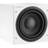
| Finish | Cabinet: | Black Ash vinyl |
| Grille: | Black cloth | |

LISTEN AND YOU'LL SEE

- ASW™ 3000 Owner's manual
- Safety Instructions
- CAUTION
- RISK OF ELECTRIC SHOCK DO NOT OPEN
- Caution:
- Explanation of Graphical Symbols
- Warnings:
- Important for UK only:
- Introduction
- Unpacking (figure 1)
- A tour of the subwoofer (figure 2)
- Positioning the subwoofer
- Electrical connections
- Application: Home Theatre
- Application: Stereo Audio
- Using more than one subwoofer
- Double check the connections
- Switching on and off
- Setting the controls
- Use with THX® controllers (including THX® controllers set in non-THX® mode)
- Use with other Home Theatre decoders
- Use for stereo audio
- Fine tuning
- Taking care of the subwoofer
- Avertissements:
- Deballage: (figure 1)
- Auspacken (figure 1)
- BVeEneHne
- PacnaKOBka (pncyHok 1)
- 3nemeHTbCa6Byepa (pnc.2)
- Pa3meueHne ca6ByΦepa
- Ha3haeHHe:
- Ctepeocntema:-O6OpyObaHne:
- IcnoJb3OBAHne DByx Nn6oJbJero KOnuYeCTBa ca6ByΦepOB
- PpOBepKa npaBnIbHocTn NOKJIoueHn
- BkIIOUeHne N BbIKIOUeHne HnpanjKeHHNITaHH
- IopraDOK BbINOpHeHn HaCTpoKn C nOMOsbIO opraHOB ynpabLeHn
- IcnoIb3ObaHne ca6BypepaDpyrMMn DeKOdepAMn DnAOMaWHN KINHOteaTPOB
- IcnoJb3OBAHne ca6ByΦepa BCTepeoΦOHnuecko cnCTeme
- ToHKaHaCTpoKa
Brand : B&W
Model : B&W ASW 3000
Category : Subwoofer