
LED-UV212 - Light projector JBSYSTEMS - Free user manual and instructions
Find the device manual for free LED-UV212 JBSYSTEMS in PDF.
User questions about LED-UV212 JBSYSTEMS
0 question about this device. Answer the ones you know or ask your own.
Ask a new question about this device
Download the instructions for your Light projector in PDF format for free! Find your manual LED-UV212 - JBSYSTEMS and take your electronic device back in hand. On this page are published all the documents necessary for the use of your device. LED-UV212 by JBSYSTEMS.
USER MANUAL LED-UV212 JBSYSTEMS
Copyright © 2010 by BEGLEC NV
t Hofveld 2C B1702 Groot-Bijaarden Belgium
Reproduction or publication of the content in any manner, without express permission of the publisher, is prohibited.

Version: 1.0


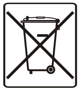
EN - DISPOSAL OF THE DEVICE
Dispose of the unit and used batteries in an environment friendly manner according to your country regulations.
FR-DECLASSES L'APPAREIL
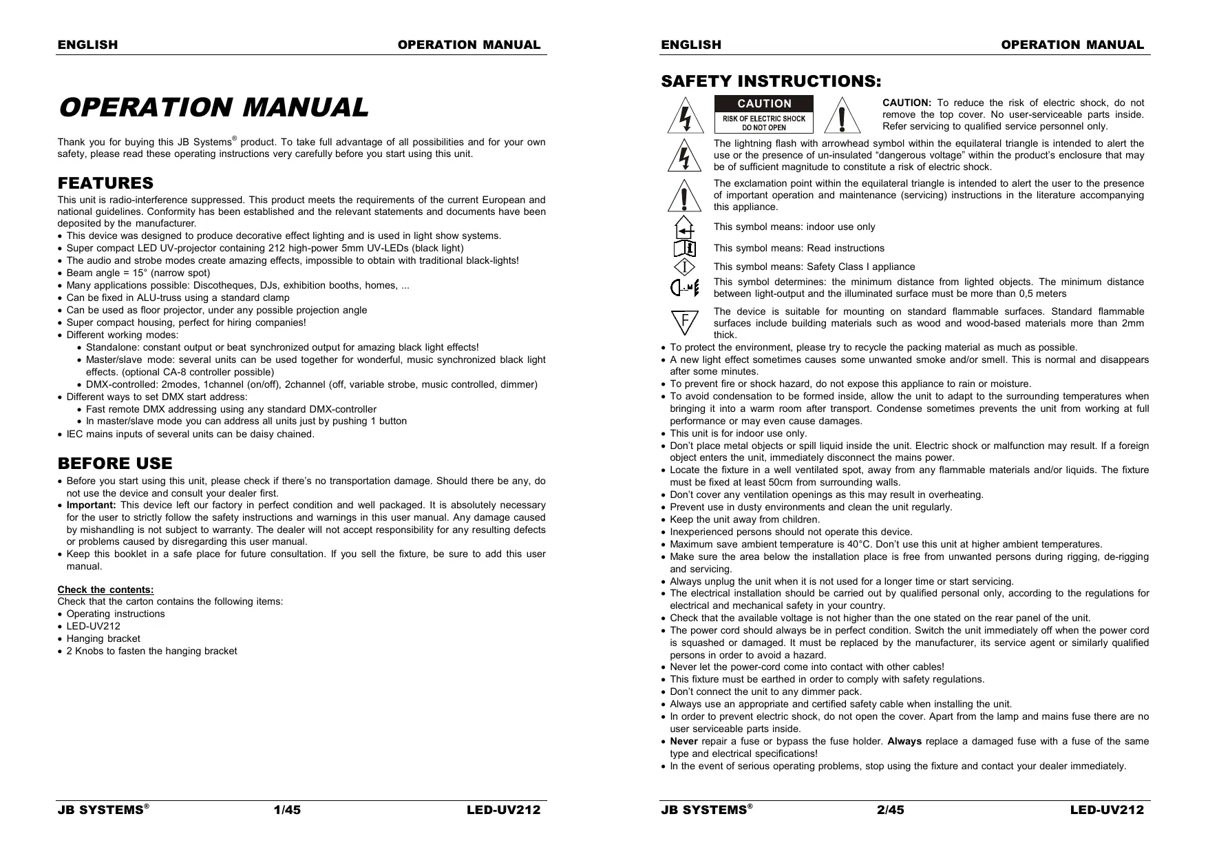
Thank you for buying this JB Systems® product. To take full advantage of all possibilities and for your own safety, please read these operating instructions very carefully before you start using this unit.
FEATURES
This unit is radio-interference suppressed. This product meets the requirements of the current European and national guidelines. Conformity has been established and the relevant statements and documents have been deposited by the manufacturer.
-
This device was designed to produce decorative effect lighting and is used in light show systems.
-
Super compact LED UV-projector containing 212 high-power 5mm UV-LEDs (black light)
The audio and strobe modes create amazing effects, impossible to obtain with traditional black-lights!
-
Beam angle = 15° (narrow spot)
-
Many applications possible: Discotheques, DJs, exhibition booths, homes, ...
-
Can be fixed in ALU-truss using a standard clamp
-
Can be used as floor projector, under any possible projection angle
-
Super compact housing, perfect for hiring companies!
-
Different working modes:
-
Standalone: constant output or beat synchronized output for amazing black light effects!
- Master/slave mode: several units can be used together for wonderful, music synchronized black light effects. (optional CA-8 controller possible)
-
DMX-controlled: 2modes, 1channel (on/off), 2channel (off, variable strobe, music controlled, dimmer)
-
Different ways to set DMX start address:
-
Fast remote DMX addressing using any standard DMX-controller
-
In master/slave mode you can address all units just by pushing 1 button
-
IEC mains inputs of several units can be daisy chained.
BEFORE USE
- Before you start using this unit, please check if there's no transportation damage. Should there be any, do not use the device and consult your dealer first.
- Important: This device left our factory in perfect condition and well packaged. It is absolutely necessary for the user to strictly follow the safety instructions and warnings in this user manual. Any damage caused by mishandling is not subject to warranty. The dealer will not accept responsibility for any resulting defects or problems caused by disregarding this user manual.
- Keep this booklet in a safe place for future consultation. If you sell the fixture, be sure to add this user manual.
Check the contents:
Check that the carton contains the following items:
- Operating instructions
LED-UV212 - Hanging bracket
- 2 Knobs to fasten the hanging bracket
SAFETY INSTRUCTIONS:

CAUTION
RISK OF ELECTRIC SHOCK DO NOT OPEN

CAUTION: To reduce the risk of electric shock, do not remove the top cover. No user-serviceable parts inside. Refer servicing to qualified service personnel only.

The lightning flash with arrowhead symbol within the equilateral triangle is intended to alert the use or the presence of un-insulated "dangerous voltage" within the product's enclosure that may be of sufficient magnitude to constitute a risk of electric shock.

The exclamation point within the equilateral triangle is intended to alert the user to the presence of important operation and maintenance (servicing) instructions in the literature accompanying this appliance.
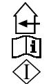
This symbol means: indoor use only
This symbol means: Read instructions
This symbol means: Safety Class I appliance
This symbol determines: the minimum distance from lighted objects. The minimum distance between light-output and the illuminated surface must be more than 0,5 meters

The device is suitable for mounting on standard flammable surfaces. Standard flammable surfaces include building materials such as wood and wood-based materials more than 2mm thick.
- To protect the environment, please try to recycle the packing material as much as possible.
- A new light effect sometimes causes some unwanted smoke and/or smell. This is normal and disappears after some minutes.
- To prevent fire or shock hazard, do not expose this appliance to rain or moisture.
- To avoid condensation to be formed inside, allow the unit to adapt to the surrounding temperatures when bringing it into a warm room after transport. Condense sometimes prevents the unit from working at full performance or may even cause damages.
- This unit is for indoor use only.
- Don't place metal objects or spill liquid inside the unit. Electric shock or malfunction may result. If a foreign object enters the unit, immediately disconnect the mains power.
- Locate the fixture in a well ventilated spot, away from any flammable materials and/or liquids. The fixture must be fixed at least 50cm from surrounding walls.
- Don't cover any ventilation openings as this may result in overheating.
- Prevent use in dusty environments and clean the unit regularly.
- Keep the unit away from children.
- Inexperienced persons should not operate this device.
Maximum save ambient temperature is 40^ . Don't use this unit at higher ambient temperatures. - Make sure the area below the installation place is free from unwanted persons during rigging, de-rigging and servicing.
- Always unplug the unit when it is not used for a longer time or start servicing.
- The electrical installation should be carried out by qualified personal only, according to the regulations for electrical and mechanical safety in your country.
- Check that the available voltage is not higher than the one stated on the rear panel of the unit.
- The power cord should always be in perfect condition. Switch the unit immediately off when the power cord is squashed or damaged. It must be replaced by the manufacturer, its service agent or similarly qualified persons in order to avoid a hazard.
- Never let the power-cord come into contact with other cables!
- This fixture must be earthed in order to comply with safety regulations.
- Don't connect the unit to any dimmer pack.
- Always use an appropriate and certified safety cable when installing the unit.
- In order to prevent electric shock, do not open the cover. Apart from the lamp and mains fuse there are no user serviceable parts inside.
- Never repair a fuse or bypass the fuse holder. Always replace a damaged fuse with a fuse of the same type and electrical specifications!
-
In the event of serious operating problems, stop using the fixture and contact your dealer immediately.
-
The housing and the lenses must be replaced if they are visibly damaged.
- Please use the original packing when the device is to be transported.
- Due to safety reasons it is prohibited to make unauthorized modifications to the unit.
Important: Never look directly into the light source! Don't use the effect in the presence of persons suffering from epilepsy.
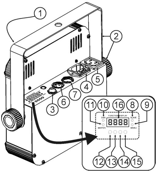
DESCRIPTION:
-
DOWN button: to go back in the menu and to lower the values shown on the display.
-
UP button: to go up in the menu and to increase the values shown on the display.
-
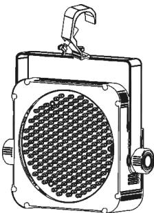
Front with hard plastic cover to protect the 5mm LEDs.
- Hanging bracket with knobs on both sides to fasten the unit and a mounting hole to fix a mounting hook.
- 14 jack used to connect the optional CA-8 controller
- Mains input with IEC socket and integrated fuse holder, connect the supplied mains cable here.
- Mains output with IEC socket: you can use a special IEC power cable to connect this output with the mains input of the next LED-UV212 for easier linking. (max 40 units can be linked)
- DMX-output connector
- DMX-input connector
- Slave LED: is lit when the unit is in slave mode
- Sound LED: blinks to the rhythm of the music while the unit is in audio mode
- DMX LED: is lit when the unit receives a DMX-signal
- Master LED: is lit when the unit is switched as master
- MENU button: used to select the different menu items
- ENTER button: used to confirm your choice.
- DISPLAY shows the various menus and the selected functions.
ELECTRICAL INSTALLATION
Important: The electrical installation should be carried out by qualified personal only, according to the regulations for electrical and mechanical safety in your country.
Electrical installation for 1 standalone unit:
- Insert the mains cable. The unit starts working immediately in the last selected stand-alone mode.
Refer to chapter HOW TO SETUP to learn how to switch between static and sound mode.
Remark: You can connect a CA-8 remote controller to the unit if you want to have more control.
Electrical installation for two or more units in master/slave:
- Connect 2 to maximum 16 units together using good quality balanced microphone cables. The unit that has no cable connected to its DMX-input is the "master", the others are the slave units.
- Make sure that all units are connected to the mains.
Refer to chapter HOW TO SETUP for more information. - Done!
Remark: You can connect a CA-8 remote controller to the master unit if you want to have more control over the master/slave operation.
Electrical installation for two or more units in DMX-mode:
- The DMX-protocol is a widely used high speed signal to control intelligent light equipment. You need to "daisy chain" your DMX controller and all the connected units with a good quality balanced cable.
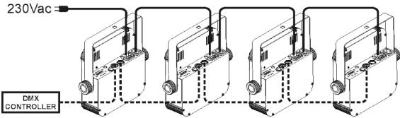
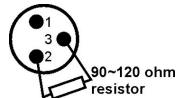
- To prevent strange behavior of the DMIX CONTROLLER light effects, due to interferences, you must use a 90 to 120 terminator at the end of the chain. Never use Y-splitter cables, this simply won't work!
- Make sure that all units are connected to the mains
Each light effect in the chain needs to have its proper start address so it knows which commands from the controller it has to decode. In the section HOW TO SETUP you will learn how to set the DMX addresses. Remember that each projector uses 1 or 2 channels, a possible address setup for 2ch mode could be: unit1 = 001 ~ unit2 = 003 ~ unit3 = 005 ~ unit4 = 007 ~ etc.
OVERHEAD RIGGING
- Important: The installation must be carried out by qualified service personal only. Improper installation can result in serious injuries and/or damage to property. Overhead rigging requires extensive experience! Working load limits should be respected, certified installation materials should be used, the installed device should be inspected regularly for safety.
- Make sure the area below the installation place is free from unwanted persons during rigging, de-rigging and servicing.
- The device should be installed out of reach of people and outside areas where persons may walk by or be seated.
- Before rigging make sure that the installation area can hold a minimum point load of 10 times the device's weight.
- Always use a certified safety cable that can hold 12times the weight of the device when installing the unit. This secondary safety attachment should be installed in a way that no part of the installation can drop more than 20cm if the main attachment fails.
- The device should be well fixed; a free-swinging mounting is dangerous and may not be considered!
- Don't cover any ventilation openings as this may result in overheating.
- The operator has to make sure that the safety-relating and machine-technical installations are approved by an expert before using them for the first time. The installations should be inspected every year by a skilled person to be sure that safety is still optimal.
HOW TO SETUP:
MAIN MENU:
- To select any of the menu options, press the MENU button up to when the required option is shown on the display.
- Select the function with the ENTER button. The display will blink.
- Use DOWN and UP button to choose the desired menu option.
- Once the required menu option is selected, press the ENTER button to select.
Remark: Press the MENU button for about 2 seconds to return to running mode or just wait 8 seconds.
The menu structure is shown below.
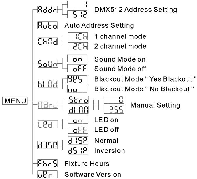

DMX512 Address Setting
Used to set the start address in a DMX setup, you can also automatically program the next LEDUV212 projectors in the same DMX-chain.
Program a DMX start address in 1 unit:
- Press the MENU button until Hddr is shown on the display.
- Press the ENTER button to select.
- Use DOWN and UP buttons to change the DMX512 address.
- Once the correct address shows on the display, press the ENTER button to confirm.
- Press the MENU button for about 2 seconds to return to running mode.
Automatically program the DMX start addresses of several units in a DMX-chain:
- Connect the DMX in/outputs of all projectors together and switch them all on
-
On the first unit in the chain:
-
Set the DMX-starts address as described above.
- After this, press the MENU button until Buto is shown on the display.
- Press the ENTER button to start the automatic programming all units flash one time to indicate that the addresses are automatically set, starting from the address programmed in the first unit.
- Press the MENU button on the first unit for about 2 seconds to return to running mode.
Example: the first projector was set to DMX-address 100 when you perform the automatic addressing, the other projectors in the DMX-chain will receive addresses: 104, 106, 108, 110, ... (given that the units are in 2ch mode)
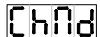
Channel Mode
The unit has 2 different channel modes. Refer to the DMX-chart to see the differences.
- Press the MENU button until chfd is shown on the display.
- Press the ENTER button to select.
- Use DOWN and UP button to select one of the available channel modes.
- Once the mode is selected, press the ENTER button to confirm.
- Press the MENU button for about 2 seconds to return to running mode.

Sound Mode
Used to choose the desired sound mode to trigger the shows.
- Press the MENU button until 50% is shown on the display.
- Press the ENTER button to select.
-
Use DOWN and UP button to select one of the available modes:
-
On (sound mode ON) the shows are triggered by the internal microphone.
-
_OFF (sound mode OFF) → the shows are triggered by the speed selected with the shows.
-
Once the right mode is selected, press the ENTER button to confirm.
- Press the MENU button for about 2 seconds to return to running mode.
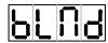
Blackout Mode
Blackout mode: when no DMX-signal is detected, the unit goes in blackout.
No blackout mode: when no DMX-signal is detected, the unit automatically switches to master mode.
ALWAYS set to "No Blackout" when the unit is used in standalone or master (master/slave) mode!!!
- Press the MENU button until blfd is shown on the display.
- Press the ENTER button.
- Use DOWN and UP button to select YES (blackout) or NO (no blackout) mode.
- Once the mode is selected, press the ENTER button to confirm.
- Press the MENU button for about 2 seconds to return to running mode.

Blackout Mode
When the unit is used in standalone mode, you can manually set the strobe and dimmer function.
- Press the MENU button until 13:40 is shown on the display.
- Press the ENTER button to select.
-
Use DOWN and UP button to select one of the 2 available options:
-
Select to select the strobe speed and press ENTER to confirm: use the DOWN and UP buttons to set the value between 000 (no strobe) and 255 (very fast strobe). Confirm with the ENTER button.
-
Select to select the dimmer setting and press ENTER to confirm: use the DOWN and UP buttons to set the value between 000 (no output) and 255 (maximum output). Confirm with the ENTER button.
-
Once both parameters are set, press the MENU button for about 2 seconds to return to running mode.

Led Display
Display on: display is always on.
Display off: display is off when not used.
- Press the MENU button until the display shows
- Press the ENTER button.
- Use DOWN and UP buttons to select on (display always on) or OFF (display off when not used).
- Once the mode is selected, press the ENTER button to confirm.
- Press the MENU button for about 2 seconds to return to running mode.

Display Inversion
Display normal: display is readable when the unit is on the floor.
Display inversion: display is readable when the unit is mounted upside down.
Press the MENU button until the display shows
- Press the ENTER button, the display starts blinking.
- Use DOWN and UP buttons to select on (display inversion) or OFF (normal display).
- Once the mode is selected, press the ENTER button to confirm.
- Press the MENU button for about 2 seconds to return to running mode.

Fixture Hours
Used to show the number of working hours of the unit.
- Press the MENU button until FhrS is shown on the display.
- Press the ENTER button to show the number of working hours in the display.
- Press the MENU button for about 2 seconds to return to running mode.

Software version:
Used to show the software version of the unit.
- Press the MENU button until Ucr is shown on the display.
- Press the ENTER button to show the software version of the unit.
- Press the MENU button for about 2 seconds to return to running mode.
OPERATING INSTRUCTIONS
A. Standalone 1unit:
- Just connect the projector to the mains and put on some music. The unit starts working automatically to the rhythm of the music.
Refer to chapter HOW TO SETUP to learn how to switch between static and sound mode.
Remark: You can connect a CA-8 remote controller to the unit if you want to have more control.
B. Two or more units in master/slave setup:
- Connect 2 to maximum 16 units together. Refer to the chapter "electrical installation" to learn how to do this.
- Connect all units to the mains and put on some music. The units will start working automatically to the rhythm of the music. Refer to chapter HOW TO SETUP for more information.
Remark: You can connect a CA-8 remote controller to the master unit if you want to have more control over the master/slave operation.
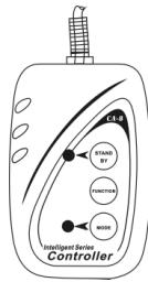
C. Connect the optional CA-8 controller for more control:
The CA-8 controller can only be used in standalone or master/slave mode. Connect the controller to the
CA-8 input of the first unit (master). Now you can control all the connected units:
| BUTTON | ACTIONS | |
| STANDBY | To blackout all the fixtures | |
| FUNCTION | 1. Synchronous strobe 2. Two light strobe | Adjust dimmer level from 000 to 255 |
| MODE | Strobe (LED OFF) | Color select (LED ON) |
D. Controlled by universal DMX-controller:
- Connect all units together. Refer to the chapter "Electrical installation for two or more units in DMX-mode" to learn how to do this (don't forget to address all units properly!)
- Connect all units to the mains and turn on the DMX controller.
Since each unit has its own DMX-address, you can control them individually. Remember that each unit uses 1 or 2 DMX-channels as shown in the DMX chart below:
| DMX512 Configuration | ||
| Ch1 | Ch1 | Ch2 |
| ON/OFF | Strobe | Dimmer |
| 128-255 ON 0-127 OFF | 249-255 Sound Active 8-248 S 0-7 Stop | 255 100% 0% |
MAINTENANCE
- Make sure the area below the installation place is free from unwanted persons during servicing.
- Switch off the unit, unplug the mains cable and wait until the unit has been cooled down.
During inspection the following points should be checked:
- All screws used for installing the device and any of its parts should be tightly fastened and may not be corroded.
- Housings, fixations and installations spots (ceiling, truss, suspensions) should be totally free from any deformation.
- When an optical lens is visibly damaged due to cracks or deep scratches, it must be replaced.
- The mains cables must be in impeccable condition and should be replaced immediately when even a small problem is detected.
- In order to protect the device from overheat the cooling fans (if any) and ventilation openings should be cleaned monthly.
- The interior of the device should be cleaned annually using a vacuum cleaner or air-jet.
-
The cleaning of internal and external optical lenses and/or mirrors must be carried out periodically to optimize light output. Cleaning frequency depends on the environment in which the fixture operates: damp, smoky or particularly dirty surroundings can cause greater accumulation of dirt on the unit's optics.
-
Clean with a soft cloth using normal glass cleaning products.
Always dry the parts carefully. - Clean the external optics at least once every 30 days.
- Clean the internal optics at least every 90 days.
Attention: We strongly recommend internal cleaning to be carried out by qualified personnel!
SPECIFICATIONS
Mains Input: 100 - 240V 50/60Hz
Power consumption: 25Watt
Fuse: 250V 6,3A slow blow (20mm glass)
IEC input/output daisy chaining: 50pcs
Sound Control: Internal microphone
DMX connections: XLR 3pin
LEDs: 212 high power UV-LEDs
Beam angle: 15^
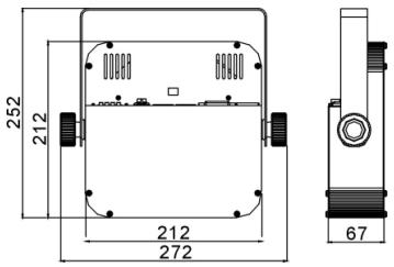
Size: see drawing below
Weight: 1,6kg
Every information is subject to change without prior notice
You can download the latest version of this user manual on our website: www.beglec.com
MODE D'EMPLOI
Channel Mode (Mode canal)
Super compacte UV LED projector met 212 high-power 5mm UV LEDs