
CR-410 - Spectrophotometer KONICA - Free user manual and instructions
Find the device manual for free CR-410 KONICA in PDF.

User questions about CR-410 KONICA
0 question about this device. Answer the ones you know or ask your own.
Ask a new question about this device
Download the instructions for your Spectrophotometer in PDF format for free! Find your manual CR-410 - KONICA and take your electronic device back in hand. On this page are published all the documents necessary for the use of your device. CR-410 by KONICA.
USER MANUAL CR-410 KONICA
E Instruction Manual
The following symbols are used in this manual to prevent accidents which may occur as a result of incorrect use of the instrument.

Denotes a sentence regarding a safety warning or note. Read the sentence carefully to ensure safe and correct use.

Denotes a prohibited operation. The operation must never been performed.

Denotes an instruction.
The instruction must be strictly adhered to.

Denotes an instruction.
Disconnect the AC adapter from the AC outlet.

Denotes a prohibited operation.
Never disassemble the instrument.
Notes on This Manual
- Copying or reproduction of all or any part of the contents of this manual without KONICA MINOLTA's permission is strictly prohibited.
- The contents of this manual are subject to change without prior notice.
- Every effort has been made in the preparation of this manual to ensure the accuracy of its contents. However, should you have any questions or find any errors, please contact a Konica Minolta authorized service facility.
- KONICA MINOLTA will not accept any responsibility for consequences arising from the use of the instrument.
To ensure correct use of this instrument, read the following points carefully and adhere to them. After you have read this manual, keep it in a safe place where it can be referred to anytime a question arises.
| WARNING (Failure to adhere to the following points may result in death or serious injury.) | |
| Do not use the instrument in places where flammable or combustible gases (gasoline etc.) are present. Doing so may cause fire. | Do not disassemble or modify the in-strument or the AC adapter. Doing so may cause a fire or electric shock. |
| Always use the AC adapter supplied as a standard accessory or the optional AC adapter, and connect it to an AC outlet of the rated voltage and frequency. If the AC adapters other than those specified by KONICA MINOLTA are used, this may result in damage to the unit, fire or electric shock. | The instrument should not be operated if it is damaged or AC adapter is damaged, or if smoke or odd smells occur. Doing so may result in a fire. In such situations, turn the power OFF immediately, disconnect the AC adapter from the AC outlet (or remove the batteries if they are used) and contact the nearest KONICA Minolta authorized service facility. |
| If the instrument will not be used for a long time, disconnect the AC adapter from the AC outlet. Accumulated dirt or water on the prongs of the AC adapter's plug may cause a fire and should be removed. | Do not connect or disconnect the AC adapter with wet hands. Doing so may cause electric shock. |
| Take special care not to allow liquid or metal objects to enter the instrument. Doing so may cause a fire or electric shock. Should liquid or metal objects enter the instrument, turn the power OFF immediately, disconnect the AC adapter from the AC outlet, and contact the nearest KONICA Minolta authorized service facility. | Do not dispose of batteries in fire, short their terminals, apply heat to them, or disassemble them. Also, do not recharge them. Doing so may cause explosion or heat generation, resulting in fire or injury. |
| Should liquid leak from batteries and contact to eye, wash liquid off with clean water without rubbing eyes and immediately seek for medical professional's advice. In case liquid contacts with hand or clothes, wipe it off with plenty of water. Avoid further use of such unit. | Insulate battery contact with such object as tape in disposing of batteries. Contact to other metal object may cause explosion or fire. Follow local regulation for proper disposal or recycling of batteries. |
| CAUTION (Failing to adhere to the following points may result in injury or damage to the instrument or other property.) | |
| Do not perform measurement which the measurement aperture directed towards your face. Doing so may damage them. | Do not place the instrument on an unstable or sloping surface. Doing so may result in its dropping or overturning, causing injury. Take care not to drop the instrument when carrying it. |
| Do not use batteries other than those specified by KONICA MINOLTA. When installing batteries in the instrument, make sure that they are correctly oriented according to the (+) and (-) marks. Failure to adhere to these instructions may cause batteries to explode or leakage of electrolytes, resulting in fire, injury or air pollution. | When using an AC adapter, make sure that the AC outlet is located near the in-strument and that the AC adapter can be connected to and disconnected from the AC outlet easily. |
Introduction
This instrument is a high-precision, light-weight Chroma Meter developed for Absolute Measurement and Difference Measurement in a wide range of fields. Measurement can be made in conjunction with a multi-functional data processor or with the Measuring Head alone.
Layout of This Manual
- This manual describes the CR-400 and CR-410. The CR-400 is used for illustrations, and any differences have been pointed out clearly so the manual may be used equally for both models.
- The manual is divided into two sections covering the Measuring Head and one section on the data processor. See following chapters for your use.
Chapter 1 Measuring Head 1 (P.21-)
When using the measuring head alone.
Chapter 2 Measuring Head 2 (P.53-)
When using the measuring head separately from the data processor after setting.
- The measuring head cannot be set by itself, but functions which run by setting the head using the optional CR-400 utility software CR-S4w or the Color data software ChromaMagic CR-S3w are described.
Chapter 3 Data Processor (P.57-)
When using the measuring head and the data processor together.
(Data Processor)
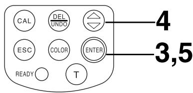
key: moves cursor or scrolls screen left and right.
key: moves cursor or scrolls screen up and down.
- This instrument and the AC adapter supplied as a standard accessory have been designed exclusively for indoor use.
- Do not leave the CR-400/410 in direct sunlight or near sources of heat, such as stoves etc. The internal temperature of the instrument may become much higher than the ambient temperature in such cases.
- Do not use the CR-400/410 in areas where dust, cigarette smoke, or chemical gases are present. Doing so may cause deterioration in performance or breakdown.
- Do not use the CR-400/410 near equipment which produces a strong magnetic field (such as speakers, etc.)
- The CR-400/410 is classified as an Installation Category II (equipment which is powered by an AC adapter connected to a commercially available power source).
- The CR-400/410 is classified as a Pollution Degree 2 (equipment which may cause temporary electrical hazards due to contamination or condensation, or products which are used in such an environment).
- Do not use the CR-400/410 at altitudes of higher than 2000m .
- Use this instrument at ambient temperature between 0 and 40^ and relative humidity 85% or less (at 35^ ) with no condensation (*1). Operating this instrument outside specified temperature and humidity range may unsatisfy its original performance.
*1 Operating temperature/humidity range of products for North America: between 5 and 40^ and relative humidity 80% or less (at 31^ ) with no condensation
- Do not subject the CR-400/410 to strong impact or vibration.
Doing so may cause deterioration in performance or breakdown. - The measurement aperture should be protected from dirt and strong impacts. Always attach the protective cap when not in use.
- The CR-400/410 may cause interference if used near a television, radio, etc.
- Due to the effect of electrostatic discharge on or in the vicinity of CR-400, erroneous can occur. In this case please repeat the last measurement. If strong static electricity is received at the moment measurement is made, the measurement values may be adversely affected, but the following measurement will be ok.
- When using the Measuring Head upside-down, make sure no dirt or dust get into the aperture.
- When using the instrument for long periods of time, the displayed value may change depending on changes in the environment. Therefore, in order to achieve accurate measurements, we recommend that white calibration be done regularly using the white calibration plate. Doing this will automatically correct other calibration channels, so there is no need to calibrate them.
- Changes in the temperature will cause the color of the specimen to change, resulting in changes in the measurement data even if white calibration has been done. Therefore, calibration, setting of color difference target colors, and measurement should all be done at the same temperature.
- When performing continuous measurements, remove the batteries and use the AC adapter.
- Although this instrument is designed for increased accuracy in operations by internally calculating more digits than are actually displayed, some operation errors may occur in the minimum number of digits during rounding off, color space conversion, and in other situations.
- The white calibration plate is placed near the middle. When doing a calibration, use the area near the middle.
- Do not allow the white calibration plate to get scratched or stained.
- If you are not going to use the white calibration plate, close the cover to the white calibration plate to prevent entry of ambient light, as any areas exposed to such light will discolor.
- This roll paper is special paper (thermal paper) which displays color as the result of a heat-induced chemical reaction.
- Do not store in hot and/or humid places.
- Do not expose to direct sunlight, fluorescent light, or other outside light for long periods of time.
- Using roll paper which has become discolored because of the way it was stored will result in printing which is difficult to read. Use new roll paper whenever possible.
- Printed data may become difficult to read because of the way the paper has been stored. We recommend you copy any data for long-term storage.
- Since the printer uses a thermal mechanism, the ambient temperature may affect the speed and/or consistency of print.
- Make sure that the power switch is set to OFF when the CR-400/410 is not in use.
- Always use the AC adapter (AC-A17) supplied as a standard accessory and connect it to an AC outlet of the rated voltage and frequency.
- Use an AC power source which is within 10% of the rated voltage.
- A low ambient temperature will cause a drop in battery performance, with similar results for performance in terms of number of measurements and printing speed and consistency. We therefore recommend you use lithium or nickel metal-hydride batteries which can withstand changes in temperature.
- Measurement data and settings are stored in memory which is backed up by the internal backup batteries. The backup batteries are automatically charged during operation of the instrument, and can retain the contents of memory for 10 months if they have been fully charged. At time of purchase, the batteries may have already been partially discharged, so turn the power on to charge them. Charging of the backup batteries is performed continuously while the instrument is switched on, even while the instrument is being used. The batteries can be fully charged about 20 hours, and there is no danger of overcharging.
- Do not replace the internal backup batteries (type: ML2020 3V) yourself. Contact the nearest Konica Minolta authorized service facility to replace the backup batteries.
-
We recommend that you backup all important data and store it separately.
-
The CR-400/410 should be stored at temperatures between -20 and 40^ and a maximum relative humidity of 85% . Do not store it in areas subject to high temperatures, high humidity, or rapid changes of temperature, or where condensation may occur. For added safety, we recommend that it is stored with a drying agent at room temperature.
- Do not leave the CR-400/410 inside a car or in the trunk of a car. Under direct sunlight in summer, the increase in temperature can be extreme and may result in malfunction.
- Do not store the CR-400/410 in areas where dust, cigarette smoke, or chemical gases are present. Doing so may cause deterioration in performance or breakdown.
- When not using the white calibration plate, close the cover and store it.
- Do not throw away the packing materials (cardboard box, cushioning material, plastic bags, etc.). They can be used to protect the instrument during transportation to a service facility for maintenance (re-calibration etc.).
- If you are not going to be using the CR-400/410 for more than two weeks, the batteries must be removed. If the batteries are left in the instrument, leakage may occur resulting in damage to the instrument.
Notes on Cleaning
- If the CR-400/410 becomes dirty, wipe it with a soft, clean dry cloth. Never use solvents such as thinner and benzene.
- If the white calibration plate becomes dirty, wipe it gently with a soft, clean dry cloth. If dirt is difficult to remove, wipe it with lens cleaner and cloth, then dry.
- If the CR-400/410 break down, do not try to disassemble and repair it by yourself. Contact a Konica Minolta authorized service facility.
Safety Precautions 1
Introduction 2
Layout of This Manual 2
Conventions 3
Notes on Use 4
Notes on Storage 6
Notes on Cleaning 6
Contents 7
Before Use 11
Standard Accessories 11
Optional Accessories 12
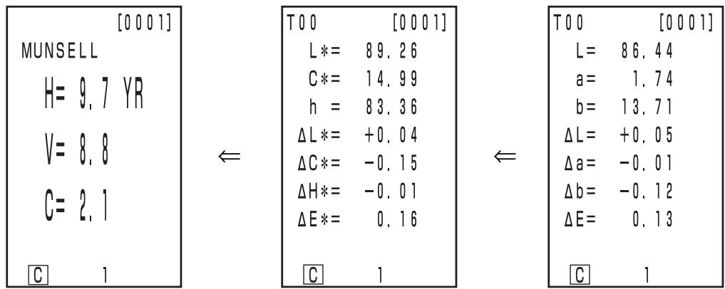
System Configuration 14
Names and Functions of Parts 15
17
18
Chapter 1 -- Measuring Head 1 --
This section describes use of the measuring head by itself.
Function guide 22
Preparation 23
Inserting the Batteries 23
Connecting the AC Adapter 25
Turning the Power ON ( | ) and OFF ( O) 27
27
Setting Language mode 28
LCD Display, Communication, and Other Settings 28
Displaying Measurement Results 30
Attaching the Wrist Strap 34
Measurement 35
Basic Operating Procedure Flow 35
White Calibration 36
Absolute Measurement 38
Color Difference Measurement 40
1) Setting a new color difference target color before every measurement 42
2) Selecting a pre-existing color difference target color before measurement 46
Functions 48
Displaying the Stored Data 48
Deleting/Undoing the Latest Data 48
User Index 48
Connecting to External Devices 49
SIP/SOP Connections 50
Chapter 2 -- Measuring Head 2 --
Using the measuring head by setting it using the data processor and then disconnecting it. This section describes functions which run by setting the measuring head using the optional CR-400 utility software CR-S4w or the Color data software ChromaMagic CR-S3w, although the head cannot be set by itself.
Additional Functions 54
- Measurement 54
54 - Display 54
54 - User Calibration 54
54
54 - Color Difference Target Color 55
55
55
55
55 - Processing Stored Data 56
56
56 - Setting 56
56
<6 Language Display> 56
56
56
56
56
56
Chapter 3 -- Data Processor --
This section describes use of the measuring head connected with the data processor.
Function guide 58
Preparation 59
Inserting the Batteries 59
Connecting the AC Adapter 61
Connecting the Measuring Head and Data Processor 63
Setting Status of Connected Measuring Head and Data Processor 64
Turning the Power ON ( | ) and OFF ( O) 65
66
Inserting the Roll Paper 67
Adjusting the Contrast of the LCD 69
Attaching the shoulder strap 69
Setting Language Mode 70
Setting Date & Time 71
Basic Setting 72
1) Printer 2) Printing color spaces 3) Data protection
4) Number of measurements for automatic average 5) Illuminant 6) Back light
7) Buzzer 8) Displayed color limit 9) Remote mode
Initial Setting 76
Displaying Measurement Results 78
Measurement 85
Basic Operating Procedure Flow 85
White Calibration 86
Absolute Measurement 88
Color Difference Measurement 90
1) Measuring a specimen and setting the data as the color difference target color. 90
2) Using the keys to set the color difference target color 93
1) Setting a new color difference target color before every measurement 98
2) Selecting a pre-existing color difference target color before measurement 102
Functions 105
Updating the Page 105
Selecting the Page 106
Displaying the Stored Data 107
Statistical Operations on Stored Data 110
Deleting the Stored Data 112
Optional Setting 115
- Elliptical tolerance 117
-Box tolerance 119
- E 121
-Box tolerance and E 123
User Index 127
Connecting to External Devices 128
SIP/SOP Connections 129
Applications 131
User Calibration Procedure Flow 131
User Calibration 132
Chapter 4 -- Description --
Principles of Measuring 142
Illumination Optics 143
User Calibration 144
Error Messages 146
Troubleshooting 148
Specifications 150
152
Dimensions 154
156
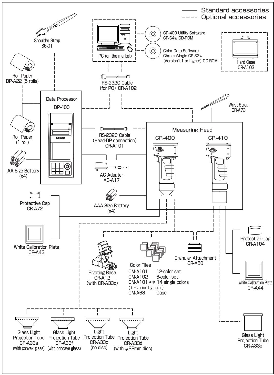
Standard Accessories
Standard accessories are available with this instrument.
In the text, "Head" indicates the Measuring Head and "DP" indicates the Data Processor.
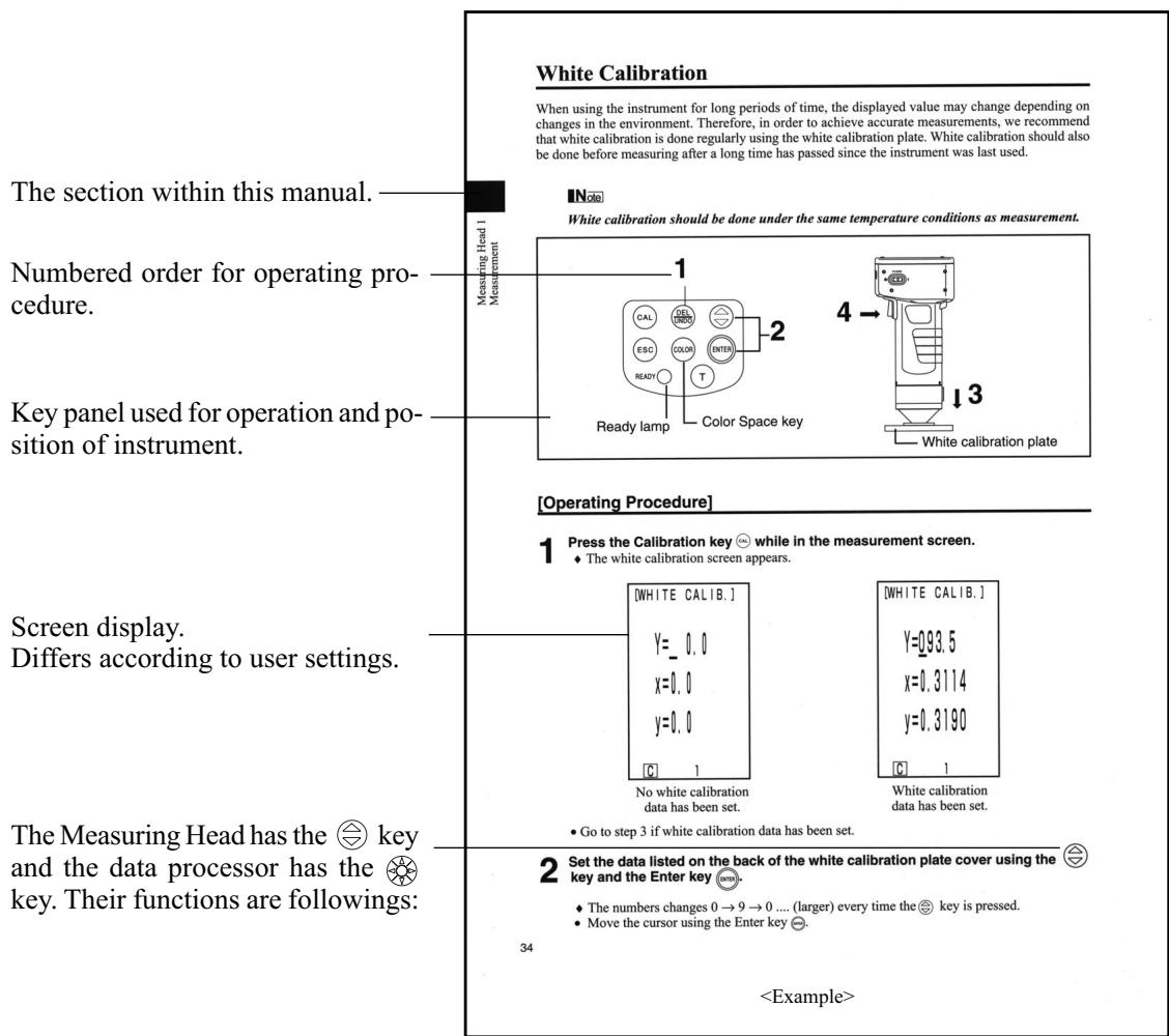
White Calibration Plate
CR-A43 (for CR-400 Head)
CR-A44 (for CR-410 Head)
Used during white calibration.
Back side of the cover lists calibration data.
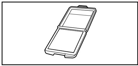
Protective Cap
CR-A72 (for CR-400 Head)
CR-A104 (for CR-410 Head)
Attaches to the tip of the light projection tube of the measuring head to protect the optics.
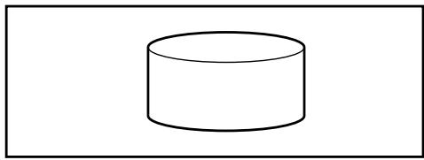
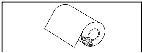
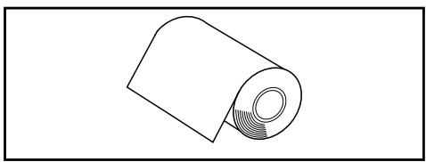
Roll Paper - 1 roll
(for data processor)
Thermal paper for the printer.
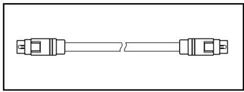
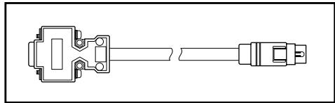
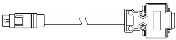
RS-232C Cable (for connecting the Head to the DP)
CR-A101 (for data processor)
Used to connect the measuring head to the data processor. (for this instrument only 13-pin specification, 1.3m long)
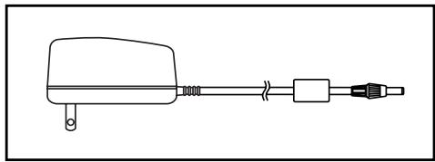
AC Adapter
AC-A17
Supplies power from an AC outlet to the instrument.
Input: 120V 50 - 60Hz0.4A (for N.America)
Input: 230V 50 - 60Hz0.4A (for worldwide except N.America)
Output: Voltage 5Vdc Current 2.8A (max.)
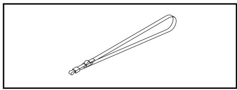
Wrist Strap
CR-A73 (for measuring head)
Attaches to the measuring head.
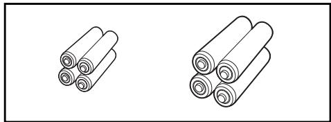
AAA Size Battery (x4)
(for measuring head)
AA Size Battery (x4)
(for data processor)
The following optional accessories should be purchased as needed.
Roll Paper-5 rolls
DP-A22 (for data processor)
Thermal paper for the printer.
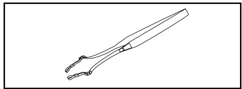
Shoulder Strap
SS-01 (for data processor)
This shoulder strap is attaches to the data processor.
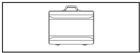
Hard Case
CR-A103
Used for storing measuring head, data processor and accessories. Do not use for transportation.
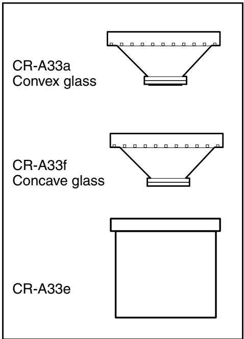
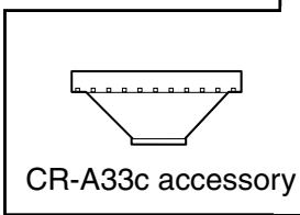
Glass Light Projection Tube
CR-A33a, A33f (for CR-400 Head)
CR-A33e (for CR-410 Head)
The glass on the tip can be used when measuring wet objects or when flattening woven cloth, etc., for measurement.
Light Projection Tube
CR-A33c,A33d (for CR-400 Head)
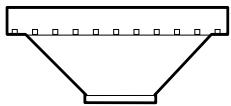
CR-A33c (no disc)
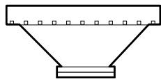
CR-A33d (with 22mm disc)
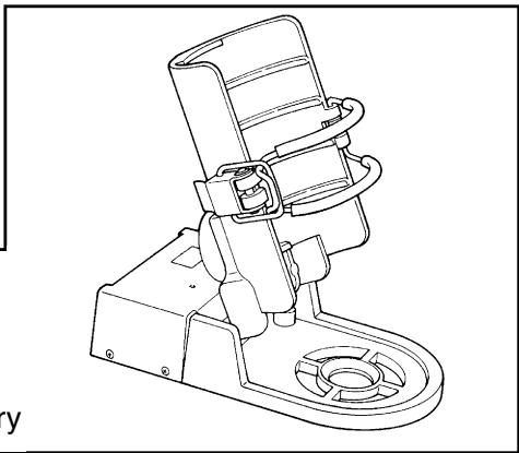
Pivoting Base
CR-A12 (for CR-400 Head)
Switching the light projection tube for the CR-400 measuring head to the CR-A33c and attaching it to the pivoting base CR-A12 allows more stable measurement as well as more accurate determining of the measuring point.
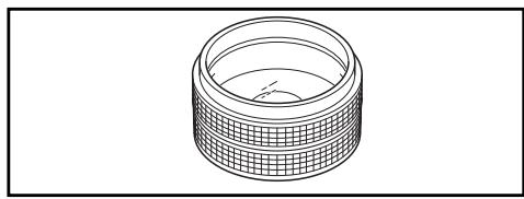
Granular Attachment
CR-A50
This allows easy, reliable, and accurate measurement of powder, grain, or paste objects.
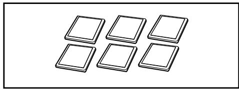
Color Tiles (for CR-400 Head)
12-color set CM-A101, 6-color set CM-A102, 14 single colors CM-A101** (** is depending on the color), case CM-A68 (stores four tiles)
The color tiles are 12 BCRA colors and white and black.
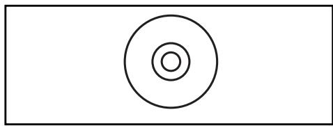
CR-400 Utility Software CR-S4w
(CD-ROM)
This software uploads measurement data, uploads and downloads of user index, converts to Excel format, and helps tweak and re-use measurement data.
Ver 1.0 or later is required for connection to this instrument.
Excel® is a trademark of Microsoft Corporation (USA) registered in US and other countries.
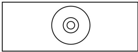
Color Data Software ChromaMagic CR-S3w
(CD-ROM)
Equipped with a variety of functions to operate the instrument using a computer, this software also provides data processing and file management functions.
Ver 1.1 or later is required for connection to this instrument.
RS-232C Cable (for PC)
CR-A102
Used to connect the measuring head or data processor to a PC.(PC connector D-sub 9 pins, 2m long)
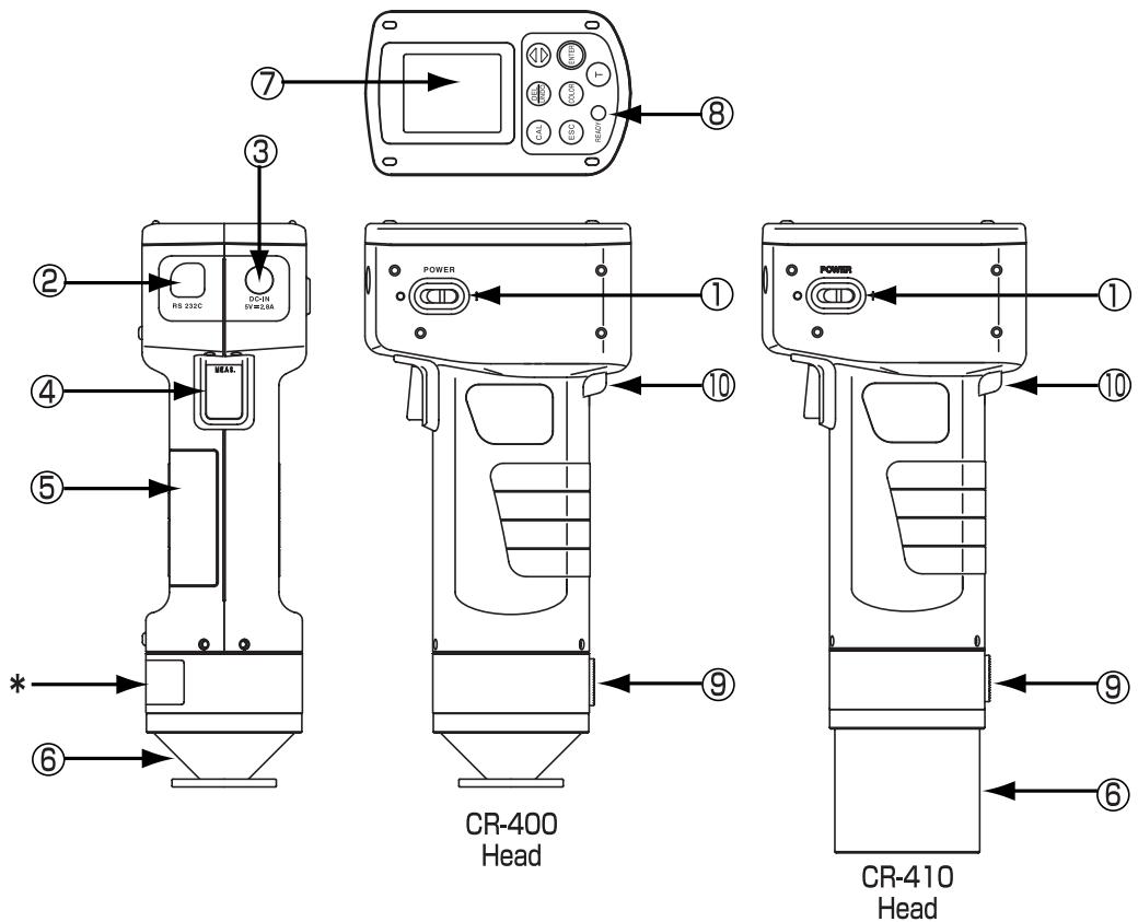
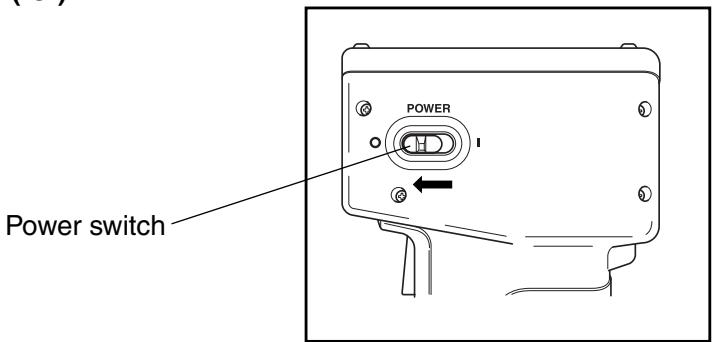
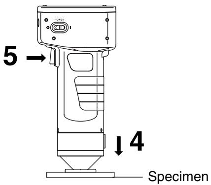
- Power switch
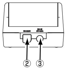
- RS-232C terminal
- AC adapter terminal
- Measurement button
- Battery chamber cover
- Light projection tube
- LCD
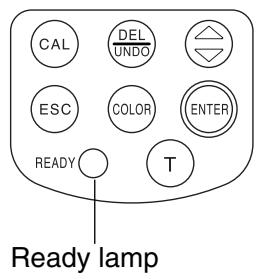
- Ready lamp
- Tripod socket
- Wrist strap attachment
: Turns ON and OFF the power.
: Connect the RS-232C cable when transmitting data back and forth to the data processor or a PC.
: Connect the connector plug for the AC Adapter (AC-A17) here when using the adapter.
: Press this to measure.
: Open and close when replacing batteries. When inserting the 4 AAA size batteries, make sure their polarity orientation is as shown.
: The CR-400 light projection tube can be replaced with the optional CR-A33a, c, d, and f light projection tubes. The CR-410 light projection tube can be replaced with the optional CR-A33e light projection tube.
: Displays measurement data and setting items.
: Ready to measure (and fully charged) when green. Always check the lamp before measuring.
: For attaching a tripod to fix the measuring head.
: The wrist strap is attached.
(Do not disassemble or modify the instrument.)
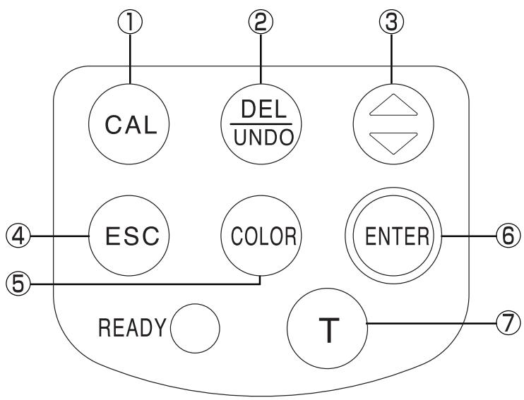
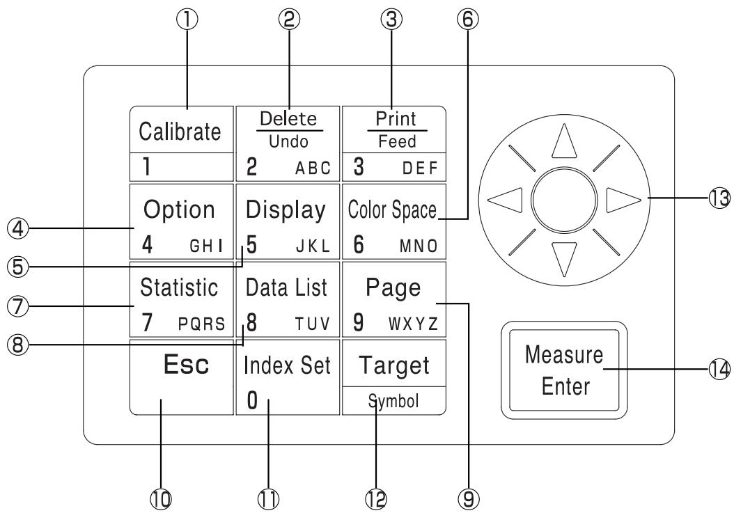
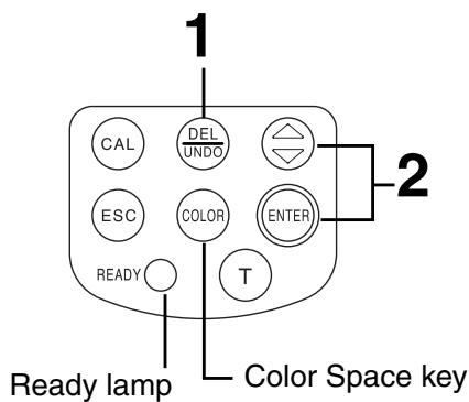
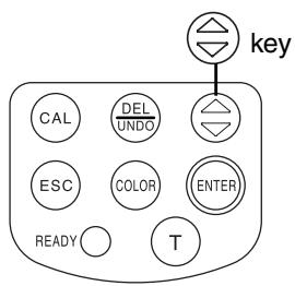
- Calibration key

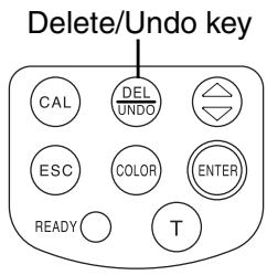
- Delete/Undo key

- Used when doing a white calibration.
- Pressing this key while in the measurement screen deletes the latest data. Pressing again, deleted data comes back. Deleted data is maintained until next measurement.
- Moves the cursor forward while pressed in the white calibration screen.
- Moves the cursor in the menu screen.
- Goes back through and displays data in the measurement or color difference target color screens.
-
Adds +1 to the value at the cursor position while in the white calibration screen.
-
key
-
Escape key

- Used to return to the measurement screen while in the menu screen.
- Used to cancel operations while in the white calibration or color difference target color screens.
- Returns to normal mode in the PC mode.
- Displays the latest data in the measurement screen.
-
Returns to display of selected color difference target color data while in the color difference target color screen.
-
Color Space key

Changes color space in the measurement screen.
- Enter key

- Pressing this key displays the menu screen while in the start-up screen.
- Changes settings for each item in the menu screen.
- Confirms the selected color difference target color in the color difference target color screen.
- Displays the color different target color screen.
- Displays the new color different target color in the color difference target color screen.
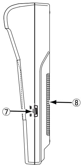
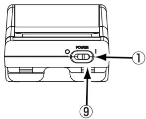
- Power switch :Turns ON and OFF the power .
- RS-232C terminal : Connect the RS-232C cable when transmitting data back and forth to the data processor or a computer.
- AC adapter terminal : Connect the connector plug for the AC Adapter (AC-A17) here when using the adapter.
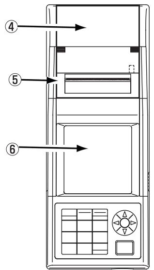
- Roll paper storage chamber: This is where the roll paper (thermal paper) is stored.
- Printer :Prints data on the roller paper (thermal paper).
- LCD : Displays measurement data and setting items.
- Display contrast : Turning the dial adjusts the contrast of the display to the most appropriate level.
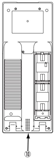
- Battery chamber cover : Open and close when replacing batteries. When inserting the 4 AA size batteries, make sure their polarity orientation is as shown.
- Shoulder strap attachment : The optional shoulder strap is attached.
- Buzzer : Buzzer sounds.
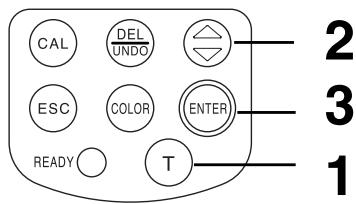
Each key sometimes works to activate a function and sometimes simply to input a number or a letter.
[As function keys]
- Calibration key
![KONICA CR-410 - [As function keys] - 1](/content/2025/01/172144/images/defe350dc6248cf808c4734ebf72737042d3e002e4d92907be9c43affa558fe6.jpg)
-
Used when doing a white calibration. (only when connected to the measuring head)
-
Delete/Undo key
![KONICA CR-410 - [As function keys] - 2](/content/2025/01/172144/images/bb6551264168f5b0671604e39720b5acf605741a6a7a19c2f61248088f7540e6.jpg)
- Pressing this key while in the measurement screen deletes the latest data. Pressing again, deleted data comes back. Deleted data is maintained until next measurement.
- Deletes or undo a data displayed in the data list.
- Deletes a page while data list is displayed in the page data list.
- Deletes a color difference target color while a color difference target color list is displayed in the color difference target color.
-
Deletes user calibration channels while the calibration channel list is displayed.
-
Print/Paper Feed key
![KONICA CR-410 - [As function keys] - 3](/content/2025/01/172144/images/4acdaf37335f2e35232b51b6adc330ffaa394b890f7e393668b06453a3389360.jpg)
-
Prints currently displayed measurement results, color difference target value, statistical operation results, stored data in a data list, or all data in a page.
-
Option key
![KONICA CR-410 - [As function keys] - 4](/content/2025/01/172144/images/050de4b72ed0ee597eed3ad75ee412a3eb88acd86b97029c65da4b69aef75f50.jpg)
-
Feeds the roll paper when pressed for a long time.
-
Displays the option screen (tolerance, automatic measurement, date & time, import, multi-calibration). (only when connected to the measuring head)
-
Change Display key Display 5JKL Changes the display format while in the measurement screen or while stored data is displayed in the data list.
- Color Space key Color Space 6 MNO Changes the color space while in the measurement screen or while stored data is displayed in the data list.
- Statistical Operation key Statistic 7 pRgS Statistically calculates the stored data per page.
8.Data List Key Calls stored data a page. - Page key
- Escape key Esc Cancels current operation or returns to previous screen.
- Returns to the latest data while in the measurement screen.
- Index Set key Set 0 - Displays the item setting screen (printer, printing color spaces, data protection, number of measurements for automatic average, illuminant, back light, buzzer, displayed color limit, and remote mode).
- Target Color key Symbol - Displays the screen for editing the currently selected color difference target color. (Only when Measuring Head is connected.)
-
Cursor key Moves the cursor up, down, left, and right. (Up/down keys)
-
Adds ± 1 to the displayed data number while in the measurement screen or while stored data is displayed in the data list. (Left/right keys)
-
Adds ± 10 to the displayed data number while in the measurement screen or while stored data is displayed in the data list.
-
Moves to the next page when displaying data that does not all fit in single group while item, displayed color limit, or page/color difference target color/user calibration channel lists are displayed.
-
Measure/Enter key Measure while in the measurement screen.
-
Calibrates while in the white calibration or user calibration screens.
- Measures color difference target color. (When the value has not been input in the color difference target color screen.) (Only when the measuring head is connected)
- Changes the setting of the item at the cursor position, in the item setting screen.
- Selects the item at the cursor position in any other screen.
When an error screen is displayed, you can return to the original screen by pressing any key. However, if the power save function is activated when an error screen is displayed, the error screen is retained without showing the power save mode. In this case, pressing any operation key or measurement button resets the power save mode, and displays the error screen. (The screen indication does not change.) If the operation key is pressed again, the display returns to the original screen.
![KONICA CR-410 - [As function keys] - 5](/content/2025/01/172144/images/1e9a9f1e968d9f2e3f2423718fd7041ef13534c541f129e6e34e86819184dc8d.jpg)
[As input keys]
- Numeric pad
![KONICA CR-410 - [As input keys] - 1](/content/2025/01/172144/images/e3dbe6dae2280f60c155a21f1fe8b8556a25d501dc311ba5377c600c6c1a0008.jpg)
- Numeric input is used for white calibration values, selected calibration, color difference target color data, color difference restriction, the clock, the timer, and the CMC parameter input screen.
-
Letter input is used in the selected calibration channel name and color difference target color name input screens.
-
Target Color key
![KONICA CR-410 - [As input keys] - 2](/content/2025/01/172144/images/1d0d2b059aa6c7663b8884689194cb5f28fe0588408ef965f52402f9a09086c2.jpg)
- Enters the following symbols at the letter or numeric input above. ('sp' = space.)
$$ \begin{array}{c} \text {U p p e r c a s e L a t i n l e t t e r s} \ \text {S m a l l c a s e L a t i n l e t t e r s} \ \text {s p !}" # \$ \% & \ \text {、} {\mid } \end{array} (\text {)} ^ {*} +, - . / :; < = > ? @ [ ? ] ^ {\wedge} _ {-} $$
$$ \begin{array}{c} \boxed {\text {N u m b e r s}} \ \text {s p . + -} \end{array} $$
-
In the filed that need numeric entry, available character types are automatically fixed. In the sign entry field, the "+" or "-" sign is alternately selected. In other fields, a space is entered.
-
Up/Down key
![KONICA CR-410 - [As input keys] - 3](/content/2025/01/172144/images/d9a41134770415931b013c6bd9caf572b05c2772062919401b52e3d0c5751aa8.jpg)
- Changes input letter type. Pressing the cursor key up: upper case Latin letters lower case Latin letters numbers upper case Latin letters, ....
- Moves the cursor when it can move up or down in the following screen: white calibration values, user calibration, color difference target color data, color difference tolerance input, date & time, and end time of the timer
-
Adds ± 1 to values.
-
Left/Right key
![KONICA CR-410 - [As input keys] - 4](/content/2025/01/172144/images/a4979a5925fde823ef1ef5c92345ac75b0a9c0ef48490c676ea296ed7a581f06.jpg)
-
Moves the cursor when it can move left or right.
-
Escape key
![KONICA CR-410 - [As input keys] - 5](/content/2025/01/172144/images/755bed5ad3a8d31e08ed23c18dc1398cdf704316623cf96b117015dea7a150fb.jpg)
-
Cancels numeric or letter input.
-
Measure/Enter key
![KONICA CR-410 - [As input keys] - 6](/content/2025/01/172144/images/9f0fb51438fbe6f86dacb02c629d0ac7715d0d50c607a37cf89a3a915f15f06a.jpg)
- Confirms input of numbers or letters.
Chapter 1
- Measuring Head 1 -
This chapter describes how to use the measuring head alone.
The Measuring Head has the following functions available depending on how it is used.
1) Functions surrounded by in the following table can be used with the Measuring Head alone. (See P.21 "Chapter 1 Measuring Head I".)
2) Other functions can be set using the Data Processor when using the Measuring Head separately from the Data Processor.
- See P.58 "Data Processor: Function guide" for details on functions available when connected to the Data Processor.
See P.35 "Measurement" for details on color measurement and color difference measurement.
| Index | Function | Reference page | |
| Initial setting | Initial setting | Initialization | 56 |
| Language mode | Language selection | ||
| Calibration | White calibration | Entry of calibration values | 36 |
| Display | Change display | Absolute values/Color difference display | 30 |
| Change display | 54 | ||
| Absolute value display | |||
| Color difference display | |||
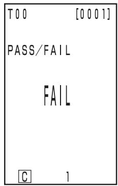
| Pass/Caution/Fail display | 55 | ||
| Color space | Color space selection | 31 | |
| Color difference target colors | Color difference target colors | Target color setting (measurement value entry) | 40 |
| Target color selection | 46 | ||
| Target color setting (value entry) | 55 | ||
| Target color character string | |||
| Delete one target color/all target colors | |||
| Overwrite confirm | 28 | ||
| Processing stored data | Data list | Selection 1 data retrieval | 48 |
| Deleting/Undoing the latest data | |||
| Basic settings | Backlight | Setting | 28 |
| PC mode | 49 | ||
| Average measurement | Setting | 54 | |
| Data protection | 56 | ||
| Illuminant | |||
| Color space limit | |||
| CMC parameter | |||
| Option setting | Clock | ||
| Data transfer | 56 | ||
| Multi-calibration | 54 | ||
| Other settings | LCD contrast | Setting | 28 |
| Baud rate setting | |||
(2) above can be set using the optional CR-400 utility software CR-S4w and the Color data software ChromaMagic CR-S3w as well. See the software manuals for details.
- User index displays can also be registered from the optional software. (See P.48.)
Preparation
Inserting the Batteries
To supply power to the instrument, the AC adapter (AC-A17) or 4 AAA size batteries must be used. Use either the AC adapter or batteries, according to which suits your application.

WARNING

Do not dispose of batteries in fire, short their terminals, apply heat to them, or disassemble them. Also, do not recharge them. Doing so may cause explosion or heat generation, resulting in fire or injury.

CAUTION

Do not use batteries other than those specified by KONICA MINOLTA. When installing batteries in the instrument, make sure that they are correctly oriented according to the (+) and (-) marks. Failure to adhere to these instructions may cause the batteries to explode or leakage electrolytes, resulting in fire, injury, or air pollution.
Notes on Use
- If you are not going to use the instrument for more than two weeks, make sure that the batteries are removed. If the batteries are left in the instrument for long periods of time, battery electrolyte may leak and damage the instrument.
- Do not touch the terminals inside the battery chamber. Doing so may result in breakdown of the instrument.
Recommended batteries
- Since a low temperature reduces the battery performance, the number of measurements and the printing speed and darkness of the characters also deteriorates. We therefore recommend using lithium or nickel metal-hydride batteries which are good in low temperatures.
[Operating Procedure]
1 Turn the power switch to OFF (O) and open the battery chamber cover on the side of the measuring head.
Battery chamber cover
![KONICA CR-410 - [Operating Procedure] - 1](/content/2025/01/172144/images/232e0568dccfbea41d0e5d0017fb4aff632445a8b13e0a3556ecd6a37fbc6482.jpg)
2 Insert 4 AAA size batteries in accordance with the polarity indications shown in the battery chamber.
Boot switch
![KONICA CR-410 - [Operating Procedure] - 2](/content/2025/01/172144/images/2ed64f1e8369f13b89600a69f8bd4a473bf4385cf81fc0c78d6f06e3c2120b71.jpg)
Notes on Use
Do not touch the boot switch under any circumstances as this will erase programs and data and cause circuit malfunctions.
3 Close the battery chamber cover.
Battery chamber cover

Using the instrument continuously for long periods of time or transferring data using the RS-232C terminal consumes a lot of electricity, so we recommend you use the AC adapter (AC-A17).

WARNING

Always use the AC adapter supplied as a standard accessory or the optional AC adapter, and connect it to an AC outlet of the rated voltage and frequency. If the AC adapters other than those specified by KONICA MINOLTA are used, this may result in damage to the unit, fire or electric shock.

If the instrument will not be used for a long time, disconnect the AC adapter from the AC outlet. Accumulated dirt or water on the prongs of the AC adapter's plug may cause a fire and should be removed.

Do not disassemble or modify the instrument or the AC adapter. Doing so may cause a fire or electric shock.

The instrument should not be operated if it is damaged, or AC adapter is damaged or if smoke or odd smells occur. Doing so may result in a fire. In such situations, turn the power OFF immediately, disconnect the AC adapter from the AC outlet (or remove the batteries if they are used) and contact the nearest Konica Minolta authorized service facility.

Do not connect or disconnect the AC adapter with wet hands. Doing so may cause electric shock.

CAUTION

When using an AC adapter, make sure that the AC outlet is located near the instrument and that the AC adapter can be connected to and disconnected from the AC outlet easily.
Notes on Use
- Before connecting or removing the AC adapter, make sure that power is turned OFF.
[Operating Procedure]
1 Make sure the power switch is turned OFF (O).
![KONICA CR-410 - [Operating Procedure] - 1](/content/2025/01/172144/images/2c06ef2e796f816d52356a928b4ce49840e88daf4026fff71132cec42f9dff37.jpg)
2 Connect the AC adapter connector plug to the AC adapter terminal on the rear of the instrument.
![KONICA CR-410 - [Operating Procedure] - 2](/content/2025/01/172144/images/148620bc352e73ac53a46bdea75167f3cf3280969a037b8ccf6d38d4139f0098.jpg)
3 Insert the AC adapter power plug to an AC outlet (100-240 Vac).
![KONICA CR-410 - [Operating Procedure] - 3](/content/2025/01/172144/images/92eea228d876e426e2d33b42bb1b7ffa42eb434f4367e58d4760745ba08a7879.jpg)
If the batteries are installed in measuring head and the AC adapter is used, the power is supplied by AC adapter.
[Operating Procedure]
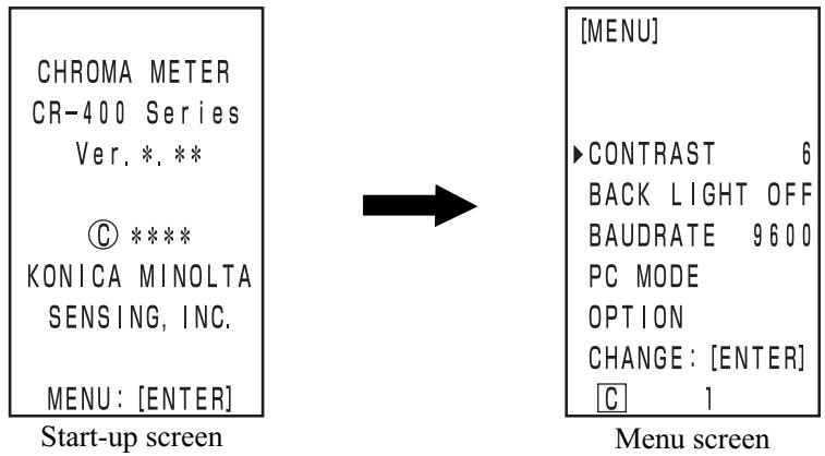
1 Set the POWER switch to (I).
- The measurement screen appears after the start-up screen.
- The PC mode screen appears when in PC mode.
[Operating Procedure]
1 Set the POWER switch to (O).
Power save mode will be activated if the measurement button and operation keys are not operated for more than three minutes. When in power save, the instrument's ready lamp goes OFF in order to stop recharging the light emission circuit. Power save mode can be disengaged by pressing any of the operating keys or the measurement button. (The key pressed when disengaging will not function.)
Data and settings in the instrument are automatically stored.
The memory is protected if the batteries are in the instrument or it is plugged in to the AC adapter and the power is ON because of power supply to the memory. The instrument also has special internal memory backup batteries, so as long as the batteries are at full charge, the contents of memory are protected for up to 10 months even if the batteries in the measuring head are removed or the AC adapter is not used. (A full charge is achieved when the AC adapter is connected continuously for 20 hours.)
The instrument's language mode is set to English when shipped from the factory.
To set a different language, the DP-400 Data Processor (see P.70 "Setting Language Mode" for details), or the optional CR-400 utility software CR-S4w or Color data software ChromaMagic CR-S3w are required.
LCD Display, Communication, and Other Settings
The following four items can be set in the instrument.
| Setting item | Value | Default | Description | |||
| 1) Contrast | 1-2 | 6 | Adjusts the contrast of the LCD. The larger value displays darker. | |||
| 2) Back light | OFF/ON | OFF | Turns the LCD backlight ON and OFF. When ON, the light comes ON for 30 seconds after key operation and then automatically goes OFF. | |||
| 3) Baud rate | 4800,9600,19200 | 9600 | This sets the baud rate, one of the communication parameters when connecting to a PC. | |||
| 4) PC mode | This switches to the mode used for communication with a PC. | |||||
| 5) Option | The option setting screen appears. | |||||
| Setting item | Value | Default | Description | |||
| Target color over-write confir-mation | OFF/ON | OFF | Specify whether to show or hide the confirmation message to ask whether the exiting color difference target color number is to be overwritten with new color difference target color measurement data. If this item is set to OFF, the system automatically overwrites existing data, without showing the confirmation message. | |||
Press the Input key (ENTER) while the start-up screen is displayed (approx. 2 seconds) after the power is turned ON.
- The menu screen appears.
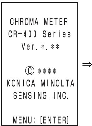
Start up screen

Menu screen
2 Move the cursor using the key to select the setting item.
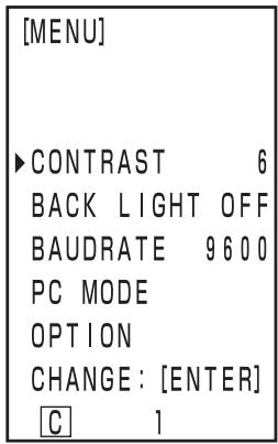
Menu screen
3 Press the Enter key (ENTER) to change the settings.
- Pressing the Enter key (ENTER) changes the setting values in the table above for each item.
- For 4) PC mode, pressing the Enter key (ENTER) switches to PC connection mode.
(See P.50 "Changing to PC Mode")
- For "5) Option", pressing the Enter key displays the option setting screen. Every time the Enter key is pressed, the ON/OFF setting alternately changes. If you press the Escape key , the system registers the current ON/OFF setting, and returns to the menu screen.
Changes are confirmed once they are changed.
4 Once settings are complete, press the Escape key (ESC).
- The display returns to the measurement screen.
The basic screen layout is shown right.
[Setting conditions]
- A color difference target color is set.
- L^a^b^* color space and absolute/color difference are selected by pressing the Color Space key (color).
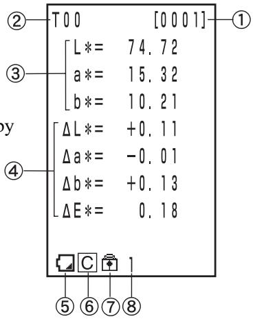
Information Display
1) Current measurement data number
2) Color difference target color number (name) for displayed measurement data
Measurement Value Display
3) Absolute measurement data
4) Color difference measurement data
Icon Display
5) Battery
The battery power is displayed in three levels. The battery level display is not shown when the AC adapter is connected.
- [No display] (when there is sufficient power or when the AC adapter is used.)

(Low Battery)
- Measurement can still be done for a while even if this is displayed. We, however, recommend replacing new batteries as soon as possible, or using AC adapter.

(Battery Out)
- When this is displayed, all operations can no longer be done. We recommend replacing new batteries quickly, or using AC adapter.
6) Illuminant
C(C): indicates CIE standard illuminant C.
D(D_65) : indicates CIE standard illuminant D_65
7) Data protection
(ON)
[No display] (OFF)
8) Number of average
"1" to "30" is displayed.
6), 7), and 8) are displayed by being set with the data processor.
See P.72 "Basic Setting" for details.
Using this instrument changes the color space for as below.
XYZ, Yxy, L*a*b, Hunter Lab, L*C*h, and Munsell (illuminant C only)
Up to 6 data can be displayed if a user index is registered. (See P.48 "User Index".)
See P.32 "Color Space and Changing the Display" and P.33 "Color Space and Color Difference Setting" for details on setting conditions for color space.
Operating Procedure
1 Press the Color Space key (COLOR) to change the color space.
- The display changes every time the key is pressed.
[Absolute value/color difference screen for color difference measurement (example)]
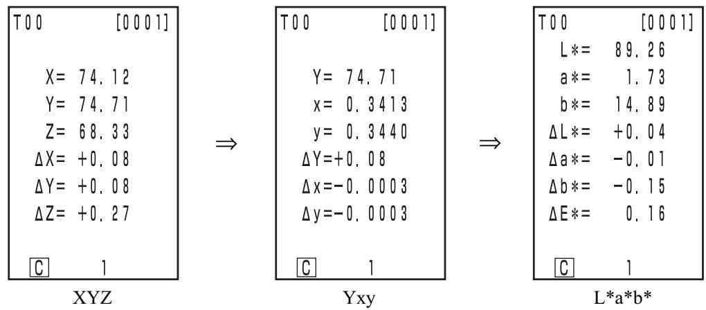
Munsell (illuminant C only)
L*C*h
Hunter Lab
- No color difference is displayed if color difference is not set.
Setting conditions of color space and symbol/illuminant/default of displayed color limit/changing display are shown as follows.
There are restrictions depending on selected color space in the following table.
- In Chapter 1 Measuring Head 1, only in the table function.
- In Chapter 2 Measuring Head 2, all displays except for Color difference graph and User index in the table function.
(O: Valid, X: Invalid)
| Color space | Symbol | Illuminant | Displayed color limit | Changing display | |||||||
| Absolute value | Color Difference | C | D65 | C | D65 | Absolute value | Color difference | Absolute value/ color difference | Judgement | Color differ- ence graph*3 | |
| XYZ | X Y Z | ΔX ΔY ΔZ | O | O | ON | ON | O | O | O | O | O |
| Yxy | Y x y | ΔY Δx Δy | O | O | ON | ON | O | O | O | O | O |
| L*a*b* | L*a*b* | ΔL*a*b* Δb* ΔE* | O | O | ON | ON | O | O | O | O | O |
| Hunter Lab | L a b | ΔL Δa Δb ΔE | O | O | ON | ON | O | O | O | O | O |
| L*C*h | L*C*h | ΔL* ΔC* ΔH* ΔE* | O | O | ON | ON | O | O | O | O*1 | O*1 |
| CMC (l:c) | L*C*h | ΔLc ΔCc ΔHc CMC | O | O | OFF (1.0:1.0) | OFF (1.0:1.0) | O | O | O | O*1 | O*1 |
| CIE1994 | L*C*h | ΔL94 ΔC94 ΔH94 ΔE94 | O | O | OFF | OFF | O | O | O | O*1 | O*1 |
| Lab99 | L99 a99 b99 | ΔL99 Δa99 Δb99 ΔE99 | O | O | OFF | OFF | O | O | O | O | O |
| LCh99 | L99 C99 h99 | ΔL99 ΔC99 ΔH99 ΔE99 | O | O | OFF | OFF | O | O | O | O*2 | O*2 |
| CIE2000 | L*C*h | ΔL00 ΔC00 ΔH00 ΔE00 | O | O | OFF | OFF | O | O | O | O*1 | O*1 |
| WI E313 | WI | ΔWI | O | X | OFF | - | O | O | O | O | X (Absolute value/color difference) |
| YI D1925 | YI | ΔYI | O | X | OFF | - | O | O | O | O | X (Absolute value/color difference) |
| YI E313 | YI | ΔYI | O | X | OFF | - | O | O | O | O | X (Absolute value/color difference) |
| Munsell | H V C | - - - | O | X | ON | - | O | X (Absolute value) | X (Absolute value) | X (Absolute value) | X (Absolute value) |
| CIE WI/Tw | WI Tw | ΔWI ΔTw | X | O | - | OFF | O | O | O | O | X (Absolute value/color difference) |
| User index *4 | Up to 9 characters | O | O | ON (At regista-tion) | ON (At regista-tion) | O | X (Absolute value) | X (Absolute value) | X (Absolute value) | X (Absolute value) | |
1: Graph display and judgement at L^ , a^ , and b^
2: Graph display and judgement at ΔL99, Δa99, and Δb99
3: Only screen display of data processor
*4: The registration by only PC is available.
Setting conditions of color space and symbol/color difference target color/color difference tolerance types are shown as follows.
There are restrictions in the following table depending on selected color space.
- In Chapter 1 Measuring Head 1, only in the table function.
- In Chapter 2 Measuring Head 2, all displays except for User index in the table function.
(O: Valid, X: Invalid)
| Color space | Symbol | Color difference target color | Color difference tolerance type | |||||
| Absolute value | Color Difference | Mesurement input | Numeric input | Elliptical tolerance | Box-type tolerance | ΔE | Box-type tolerance and ΔE | |
| XYZ | X | ΔX | O | O | O | O | O | O |
| Y | ΔY | (ΔE*) | (ΔE*) | |||||
| Z | ΔZ | |||||||
| Yxy | Y | ΔY | O | O | O | O | O | O |
| x | Δx | (ΔE*) | (ΔE*) | |||||
| y | Δy | |||||||
| L*a*b* | L* | ΔL* | O | O | O | O | O | O |
| a* | Δa* | |||||||
| b* | Δb* | |||||||
| ΔE* | ||||||||
| Hunter Lab | L | ΔL | O | O | O | O | O | O |
| a | Δa | |||||||
| b | Δb | |||||||
| ΔE | ||||||||
| L*C*h | L* | ΔL* | O | X | O*1 | O*1 | O | O*1 |
| C* | ΔC* | |||||||
| h | ΔH* | |||||||
| ΔE* | ||||||||
| CMC (l:c) | L* | ΔLc | O | X | O*1 | O*1 | O | O*1 |
| C* | ΔCc | |||||||
| h | ΔHc | |||||||
| CMC | ||||||||
| CIE1994 | L* | ΔL94 | O | X | O*1 | O*1 | O | O*1 |
| C* | ΔC94 | |||||||
| h | ΔH94 | |||||||
| ΔE94 | ||||||||
| Lab99 | L99 | ΔL99 | O | O | O | O | O | O |
| a99 | Δa99 | |||||||
| b99 | Δb99 | |||||||
| ΔE99 | ||||||||
| LCh99 | L99 | ΔL99 | O | X | O*2 | O*2 | O | O*2 |
| C99 | ΔC99 | |||||||
| h99 | ΔH99 | |||||||
| ΔE99 | ||||||||
| CIE2000 | L* | ΔL00 | O | X | O*1 | O*1 | O | O*1 |
| C* | ΔC00 | |||||||
| h | ΔH00 | |||||||
| ΔE00 | ||||||||
| WI E313 | WI | ΔWI | O | X | X | O | X | X |
| YI D1925 | YI | ΔYI | O | X | X | O | X | X |
| YI E313 | YI | ΔYI | O | X | X | O | X | X |
| Munsell | H | - | X | X | X | X | X | X |
| V | - | |||||||
| C | - | |||||||
| CIE WI/Tw | WI | ΔWI | O | X | X | O | X | X |
| Tw | ΔTw | |||||||
| User index *4 | Up to 9 characters | O*3 | O*3 | X | X | X | X | |
1: Input color difference tolerance at L^ , a^ , and b^
2: Input color difference tolerance at ΔL99, Δa99, and Δb99
3: Input at XYZ color space
*4: The registration by only PC is available.
The wrist strap is attached to the instrument as follows.
[Operating Procedure]
1 Pass the strap through the wrist strap attachment.
![KONICA CR-410 - [Operating Procedure] - 1](/content/2025/01/172144/images/7a6228b33db0fed1118716574efe8faa4653599e30252f7a9c62e4b07ea4e872.jpg)
2 Pass the strap back through, as shown in the figure at right.
![KONICA CR-410 - [Operating Procedure] - 2](/content/2025/01/172144/images/6f735f2923b871c3eafba5df30afc3b4eb5ae0430b444a041b0ca8df1b801128.jpg)
Basic Operating Procedure Flow
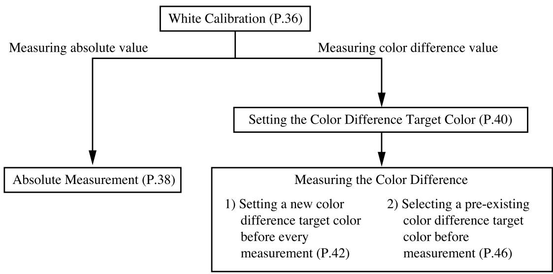
When using the instrument for long periods of time, the displayed value may change depending on changes in the environment. Therefore, in order to achieve accurate measurements, we recommend that white calibration is done regularly using the white calibration plate. White calibration should also be done before measuring after a long time has passed since the instrument was last used.
Note
White calibration should be done under the same temperature conditions as measurement.
[Operating Procedure]
Press the Calibration key _AL while in the measurement screen.
- The white calibration screen appears.
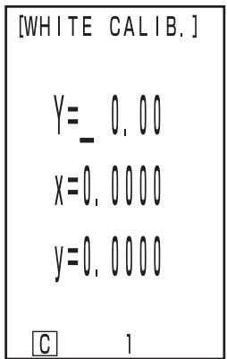
No white calibration data has been set.
White calibration data has been set.
- Go to step 3 if white calibration data has been set.
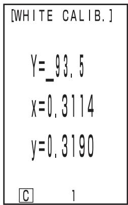
2 Set the data listed on the back of the white calibration plate cover using the key and the Enter key (ENTER).
- The numbers changes 0 9 0 ... (larger) every time the key is pressed.
- Move the cursor using the Enter key (Enter).
[Example]
- Illuminants C: Y = 93.5 x = 0.3114 y = 0.3190
Note
The illuminant is set to default C , so change the data for C . When changing D_65 , the DP-400 data processor is required. (See P72.)
The optional CR-400 utility software CR-S4w and the Color data software ChromaMagic CR-S3w can change Illuminant as well.
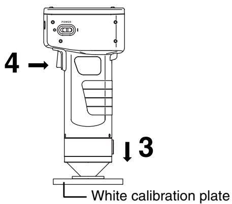
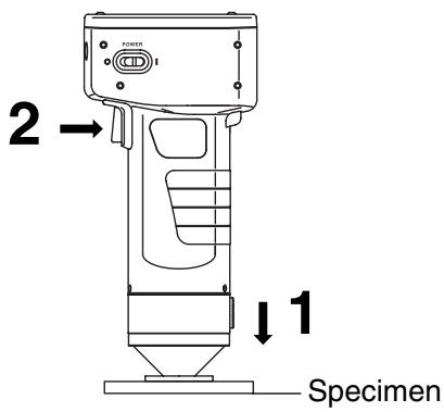
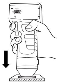
3 Place the measuring head vertically above the middle of the white calibration plate.
Note
The white calibration plate is placed near the center. Use the center area when calibrating.
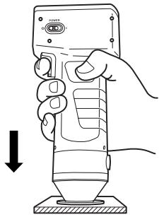
Press the measurement button after making sure the ready lamp is ON.
- Calibration is complete after the lamp flashes three times. The display returns to the measurement screen.
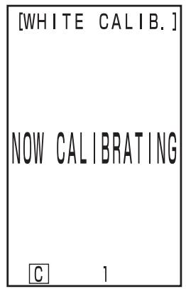
The illuminant lamp flashes three times

After calibration, the measurement screen appears.
Note
Do not move the measuring head during calibration.
With this, calibration is finished.
When measuring the chroma values (absolute values), perform P.38 "Absolute Measurement". To measure the color difference between a color difference target color and a specimen, perform P.40 "Setting the Color Difference Target Color" and P.42 "Measuring the Color Difference".
This instrument can measure reflected object color with the color space, XYZ, Yxy, Lab, Hunter Lab, LC*h, Munsell as the default.
Note
Measurement should be done under the same temperature conditions as calibration.
Note
Before Mesurement
- Select the color space for your use.
See P.31 "Selecting the Color Space" for details.
[Operating Procedure]
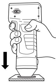
1 Place the measuring head vertically above the specimen.
![KONICA CR-410 - [Operating Procedure] - 1](/content/2025/01/172144/images/6507eb7bdeebbca331f7109bbe2d4492603da23329a8ee31cee8b76ee1b21b90.jpg)
2 Press the measurement button after making sure the ready lamp is ON.
- Measurement is done and the data is displayed.
Note
Do not move the measuring head during measurement.
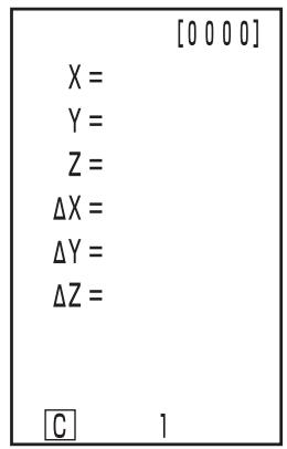
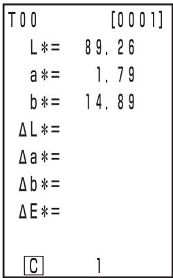
| [0001] | |
| L* = | 89.22 |
| a* = | 1.74 |
| b* = | 15.04 |
| ΔL* = | |
| Δa* = | |
| Δb* = | |
| ΔE* = | |
| C | 1 |
Mesurement data
- After measurement, pressing the Color Space key (COLOR) converts the measurement data to other color spaces. (See P.31 "Selecting the Color Space".)
- If a color difference target color is set you can display color difference data. (See P.30 "Screen Display".)
Note
- Measured data is automatically stored.
If you do not wish to store data, press the Delete/Undo key (Delete/Undo) to delete the latest data.
If you mistakenly delete data you wished to keep, press the Delete/Undo key (Delete) again and the latest deleted data is restored.
Note, however, that if new measurement data replaces the latest deleted data, that data is no longer restorable, since the new data is stored in its place. - Up to 1000 measurement data sets can be stored.
Oldest data is overwritten if this limit is exceeded.
This instrument can measure the color difference between the color difference target color and a specimen using color spaces, (XYZ), (Yxy), (Lab), (Hunter Lab), and (LCH*) as the default.
Before measuring color difference, you must set the color difference target color in the instrument.
100 color difference target colors can be set to nos. T00 to 99.

Setting color difference target colors should be done under the same temperature conditions as calibration and measurement.
The measuring head sets measurement data as the color difference target color.
When using the data processor DP-400, the color difference target color can also be set by key input.

Before Mesurement
- Select the color space for your use.
See P.31 "Selecting the Color Space" for details.
[Operating Procedure]
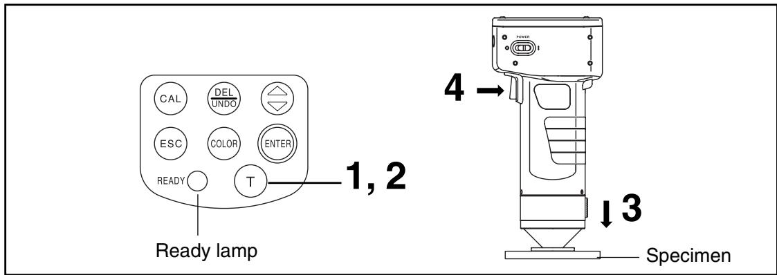
1 Press the Target Color key (Target) while in the measurement screen.
- The color difference target color setting screen appears.
Color difference target color no.
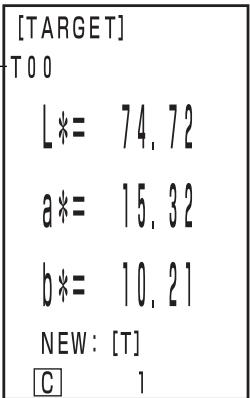
Color difference target color is set to T00.
- The first color difference target color is set to T00.
- To set the color difference target color to the currently selected color difference target color number, go to step 3.
2 Press the Target Color key (Target) to set a new color difference target color.
- The new color difference target color setting screen appears.
- When several different color difference target colors are set, select the color difference target color using the key.
Setting the color difference target color to new T01.
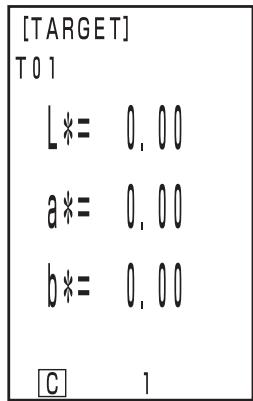
3 Place the measuring head vertically above the color difference target color specimen.
Press the measurement button of the measuring head after making sure the ready lamp is ON.
- The color difference target color is set to the selected color difference target color number and the display returns to the measurement screen.
- When not setting a new color difference target color, measuring overwrites the color difference target color data.
However, if the target color overwriting confirmation option is set to ON (see P.28), a confirmation message appears, asking whether existing data is to be overwritten. If you press the Enter key in this status, the system overwrites the color difference target color data, and returns to the measurement screen. If you press the Escape key , the system returns to the color difference target color setting screen without registering the color difference target color data. In this case, select a color difference target color number by pressing the key.
Note
Do not move the measuring head during measurement.
Note
Measurement should be done under the same temperature conditions as calibration and setting color difference target color.
1) Setting a new color difference target color before every measurement

If the same color difference target color name is used, color difference target color is overwritten. If the target color overwriting confirmation option is set to ON (see P.28), a confirmation message appears, asking whether existing data is to be overwritten.
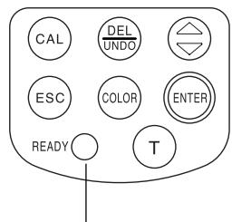
Ready lamp
Note
Before Mesurement
- Select the color space for your use.
See P.31 "Selecting the Color Space" for details.
[Operating Procedure]
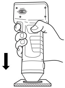
1 Place the measuring head vertically above the specimen while in the measurement screen.
![KONICA CR-410 - [Operating Procedure] - 1](/content/2025/01/172144/images/8a7155b406069dc01456199ca0a6627f989d5a9ef66cd7dd3c578bdea44dddb6.jpg)
2 Press the measurement button of the measuring head after making sure the ready lamp is ON.
- Measurement is done and the data is displayed.

Do not move the measuring head during measurement.
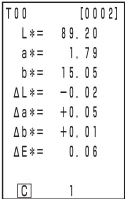
Mesurement data
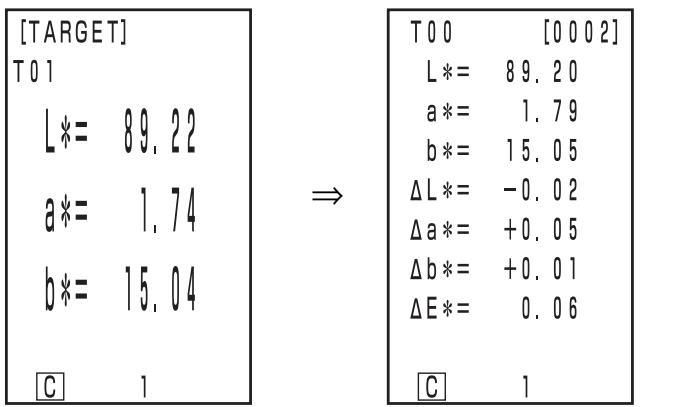
| T00 | [0002] |
| L* = 89.20 | |
| a* = 1.79 | |
| b* = 15.05 | |
| ΔL* = -0.02 | |
| Δa* = +0.05 | |
| Δb* = +0.01 | |
| ΔE* = 0.06 | |
| C | 1 |
In case of continuing to set other color difference target color and measure color difference
3 Press the Target Color key (target).
- The color difference target color setting screen appears.
- Always the same color difference target color name (T00 for example) is used and overwrites color difference target color data.
Color difference target color no.
Color difference target color is set to T00.
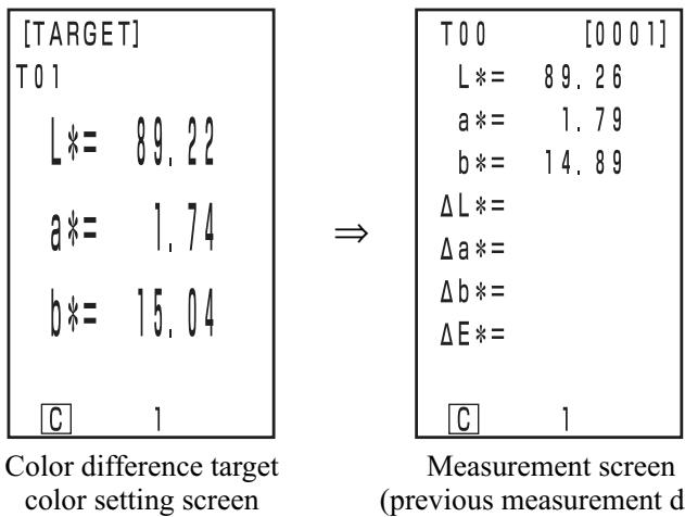
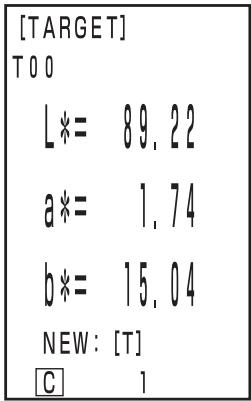
| [TARGET] | |
| T00 | |
| L*= | 89.22 |
| a*= | 1.74 |
| b*= | 15.04 |
| NEW: [T] | |
| C | 1 |
4 Place the measuring head vertically above the color difference target color specimen.
Press the measurement button of the measuring head after making sure the ready lamp is ON.
- Measuring overwrites the color difference target color data to color difference target color name T00.
If the target color overwriting confirmation option is set to ON (see P.28), a confirmation message appears, asking whether existing data is to be overwritten. Then, press the Enter key (m).
Note
Do not move the measuring head during measurement.
Color difference target color setting screen
Measurement screen (previous measurement data)
- Previously stored color difference data is not changed.
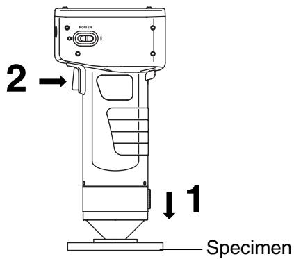
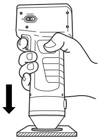
6 Place the measuring head vertically above the specimen.
7 Press the measurement button of the measuring head after making sure the ready lamp is ON.
- Measurement is done and measurement data is displayed.
Note
Do not move the measuring head during measurement.
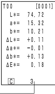
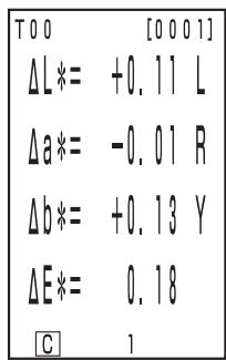
| T00 | [0003] |
| L* = 89.21 | |
| a* = 1.79 | |
| b* = 15.21 | |
| ΔL* = -0.01 | |
| Δa* = +0.05 | |
| Δb* = +0.17 | |
| ΔE* = 0.18 | |
| C | 1 |
- Repeat steps from 3 to 7.
Mesurement data
- After measurement, pressing the Color Space key (COLOR) converts the measurement data to other color spaces. (See P.31 "Selecting the Color Space".)
Note
- Measured data is automatically stored.
If you do not wish to store data, press the Delete/Undo key delete to delete the latest data.
If you mistakenly delete data you wished to keep, press the Delete/Undo key (Delete) again and the latest deleted data is restored.
Note, however, that if new measurement data replaces the latest deleted data, that data is no longer restorable, since the new data is stored in its place.
- Up to 1000 measurement data sets can be stored.
Oldest data is overwritten if this limit is exceeded.
2) Selecting a pre-existing color difference target color before measurement
Note
Before Mesurement
- Select the color space for your use.
See P.31 "Selecting the Color Space" for details.
Operating Procedure
Press the Target Color key (target) while in the measurement screen.
- The color difference target color setting screen appears.
2 Select the color difference target color using the key.
- Pressing the key changes the color difference target colors.
Setting screen
3 Press the Enter key (ENTER).
- The selection of the color difference target color is complete and returns to the measurement screen.
Mesurement data
4 Place the measuring head vertically above the specimen.
Press the measurement button of the measuring head after making sure the ready lamp is ON.
- Measurement is done and the measurement data is displayed.
Mesurement data
Note
Do not move the measuring head during measurement.
- After measurement, pressing the Color Space key (COLOR) converts the measurement data to other color spaces. (See P.31 "Selecting the Color Space".)
Note
- Measured data is automatically stored.
If you do not wish to store data, press the Delete/Undo key to delete the latest data.
If you mistakenly delete data you wished to keep, press the Delete/Undo key (Delete) again and the latest deleted data is restored.
Note, however, that if new measurement data replaces the latest deleted data, that data is no longer restorable, since the new data is stored in its place.
- Up to 1000 measurement data sets can be stored.
Oldest data is overwritten if this limit is exceeded.
Functions
Displaying the Stored Data
[Operating Procedure]
1 Press the key while in the measurement screen.
- Previous data is displayed every time the key is pressed.
- After measurement data 001, the latest data is displayed.
- Pressing the Escape key (esc) displays the latest data.
Deleting/Undoing the Latest Data
[Operating Procedure]
1 Press the Delete/Undo key while in the measurement screen.
- The latest data only is deleted.
- It is maintained until the next measurement by the internal backup battery.
2 Press the Delete/Undo key (Delete Undo).
- This undo the latest data.
- See P.56
/ for details about deleting the data except the latest data.
User Index
- It is possible to regist an operational expression based on the color space to the measuring head. Simply displaying the user's own index as measurement results eliminates the need to do calculations based on the measurement values, making more convenient color management on the job.
- A PC is used to write the operational expression to the measuring head, and up to six can be registered. This can be done automatically by connecting a data processor to the measuring head.
- The optional CR-400 utility software CR-S4w and Color data software ChromaMagic CR-S3w are needed to write the user index.
See the operation manual for the CR-400 utility software CR-S4w for details on how to write the user index.
Data can be transferred between the instrument and a PC by connecting the instrument's RS-232C terminal to a PC.
We recommend using the AC adapter (AC-A17) when connected to a PC because of the higher power consumption involved.
By connecting the instrument to a PC/AT compatible PC using the optional RS-232C cable CR-A102, the data stored in the instrument memory can be transfer each other.
Use the optional CR-400 utility software CR-S4w and the Color data software ChromaMagic CR-S3w when connecting the instrument to a PC.
The followings can be used in PC mode:
- Outputting measurement and target color data to a PC
- Reading target color data from a PC.
- Changing Settings
- Registering a User Index
See P.50 "Changing to PC Mode" for details.
Notes on Use
- When connecting, make sure that the connectors are correctly oriented and fastened securely with screws.
- Before connecting, make sure that the power to both the instrument and PC is turned OFF.
- Hold the connector when connecting or disconnecting. Do not bend, pull, or apply undue pressure to the cord, as this may cause it to break.
- Do not touch the connector terminals with your hand. Doing so may cause them to get dirty or subject them to excessive force.
- Make sure that the cable is long enough. Tensing the cable may cause connection failure or wire breakage.
-
If optional RS-232C cable CR-A102 is not used, make sure the cable specifications match the pin number/signal connection diagram for an RS-232C cable below. An inappropriate cable will prevent data from being input and output properly and may cause malfunctions.
-
Communication Parameters
| Item | Setting | ||
| Baud rate | 4800bps | 9600bps | 19200bps |
| Character length | 8bit | ||
| Parity | None | ||
| Stop bit | 1bit | ||
- RS-232C cable pin number/signal connection diagram
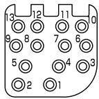
Instrument
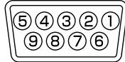
PC
(for D-sub 9 pins)
| Pin No. | Signal | Signal | Pin No. | |
| 6 | RXD | RXD | 2 | |
| 7 | TXD | TXD | 3 | |
| 8 | RTS | GND | 5 | |
| 9 | CTS | RTS | 7 | |
| 10 | GND | CTS | 8 |
- Accessories equipment connected the analog and digital interfaces must be certified to the respective IEC standards ( i.e. IEC950 for data processing equipment.)
- Furthermore all configurations shall comply with the system standard IEC 1010-1, Everybody who connects additional equipment to the signal input part or signal output part configures a electrical equipment for measurement system, and is therefore, responsible that the system complies with the requirements of the system standard (IEC 1010-1. If in doubt, consult the technical services department or your local representative.)
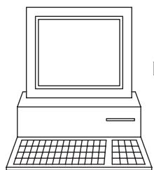
PC
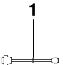
RS-232C cable CR-A102
[Operating Procedure]
1 Turn the power OFF ( O ) and connect the instrument to the PC using the RS-232C cable.
RS-232C terminal
![KONICA CR-410 - [Operating Procedure] - 1](/content/2025/01/172144/images/1b8877bf44442f96a6de2cf97f5a4d62c6a519508e6da37fd55c99d125bd6848.jpg)
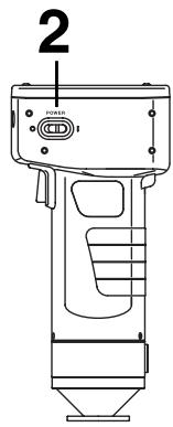
2 Turn the power ON (I).
![KONICA CR-410 - [Operating Procedure] - 2](/content/2025/01/172144/images/115a911b4ce8962a4b6451d29bc87ca6fcf92c5770a6ef5a99e9c1745788114b.jpg)
Press the Enter key (ENTER) while in the start-up screen.
- The menu screen will appear.
4 Move the cursor using the key and select "PC MODE."
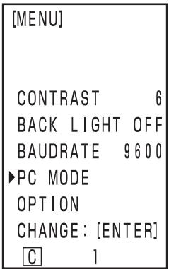
Menu screen
Press the Enter key (ENTER).
- The PC mode screen appears.
- Pressing the Escape key returns to the measurement screen.
Note
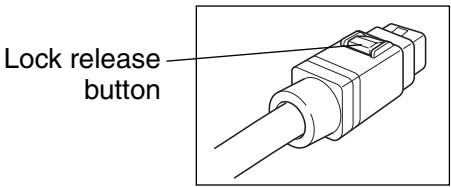
When removing the RS-232C cable, turn OFF the measuring head and data processor and push the lock release button certainly while removing the cable.
If the lock is not released and remove it by force, the connector may be damaged.
If you connect the measuring head to the data processor with the measuring head power switch turned ON when you have returned to the measurement screen with the Escape key after PC mode operation with the measuring head, a measurement error may occur, resulting in a connection failure. In this case, turn OFF the measuring head power switch, and then re-connect the measuring head to the data processor.
PC mode menu screen
Chapter 2
- Measuring Head 2 -
(Using the measuring head after setting it with the data processor)
This chapter describes functions which cannot be set with the measuring head alone, but can be set using the data processor and the optional CR-400 utility software CR-S4w and Color data software ChromaMagic CR-S3w.
- See P.63 “Connecting the Measuring Head and Data Processor” for details on how to connect the measuring head and the data processor.
Additional Functions
1. Measurement
It is possible to set the number of measurements for average to 1-30 times.
See P.72 "Basic Setting" for details on how to set this.
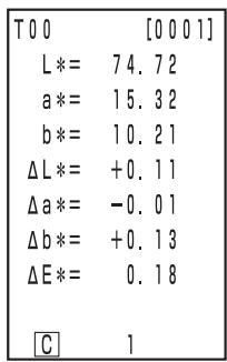
- The number of measurements is displayed at the bottom of the LCD.
- Only the average is stored.
Numbers of measurement is set to 3 times.
2. Display
- It is possible to display a larger font, in which case either the absolute value or the color difference is displayed.
When the measuring head is disconnected from the data processor and used, the display at the time of disconnection remains.
See P.81 "Screen Display and Changing the Display" for how to set this.
Absolute value/ color difference
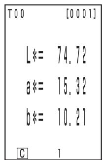
Absolute value only
Color difference only
- The selected display is maintained until removal from the data processor.
3. User Calibration
See P.131 "User Calibration Procedure Flow" for the relationship between the multi-calibration and manual select calibration.
This performs multi-calibration.
See P.135 "Setting the Multi-calibration" for details on how to set.
This selects the user calibration channel to calibrate.
See P.137 "Setting the Manual Select Calibration" for details on how to set.
The color difference target color can be set using key entry.
See P.93 "2) Using the keys to set the color difference target color"
for details on the setting procedure.
This sets a color difference target color name (not a color difference target color nos. T00 to T99) and displays the name.
See P.92 "How to set the color difference target color name" for details on the setting procedure. To change an already registered color difference target color number (name), see P.97 "How to change the color difference target color name".
Color difference target color name
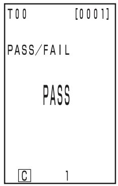
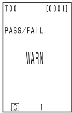
Judgment (PASS/WARN/ FAIL) can be done by setting the color difference tolerance.
See P. 116 "Setting the Color Difference Tolerance" for details on the setting procedure.
It is possible to delete color difference target colors.
See P.96 "Deleting the Color Difference Target Color" for details on how to set.
It is possible to free up memory by importing data stored in the measuring head to the data processor using the function to move data from the measuring head to the data processor. (This is the same status as all the data in the measuring head has been deleted.)
Note
When data transfer is executed, data will be transferred from the measuring head to a page in the data processor. If you only need to secure an empty space in the memory or to delete all data, and transferred data are not required, prepare or select an unnecessary page in advance, and then transfer data onto this page. After data transfer is completed, delete this page. For the page creating, selecting and deleting procedures, see P.105 "Updating the Page", P.106 "Selecting the Page", and P.112 "Deleting the Stored Data", respectively. For data transfer procedure, see P.126
See P.126 "Transfer Stored Data" for details on how to set.
6. Setting
It is possible to return to factory preset.
See P.76 "Initial Setting" for details on how to set.
<6 Language Display>
The language can be set to Japanese, English, German, French, Spanish, and Italian.
See P.70 "Setting Language Mode" for details on how to set.
The measurement time can be recorded. Although this is not displayed in the measuring head LCD, it is recorded with the measurement data and can be printed out if the measuring head is connected to the data processor. (Only statistical operation display)
See P.71 "Setting Date & Time" for details on how to set.
Using the optional CR-400 utility software CR-S4w allows you to display the date and time for each data.
The illuminant can be set to either C or D65.
See P.72 "Basic Setting" for details on how to set.
This protects existing data if the stored data exceeds 1000.
See P.72 "Basic Setting" for details on how to set.
It is possible to select not only from XYZ, Yxy, Lab, Hunter Lab, LCh*, and Munsell, but from all 15 types. (See P.78 "Selecting the Color Space" for details on color spaces.)
See P.72 "Basic Setting" for details on how to set.
It is possible to set the CMC parameter from 0.1 to 9.9.
See P.75 "CMC Parameter Setting" for details on how to set.
Chapter 3
Data Processor
This chapter describes how to use connected the Measuring Head and Data Processor.
The Data Processor has the following functions available depending on how it is used.
1) All of the following functions can be used when the Measuring Head and the Data Processor are connected. (See P.57 "Chapter 3 Data Processor).
2) Functions surrounded by in the following table can be used with the Data Processor alone.
- See P.22 "Measuring Head I and II: Function Guide" for details on the functions which can be used with the Measuring Head alone.
See P.85 "Measurement" for details on color measurement and color difference measurement.
| Index | Function | Reference page | |
| Initial settings | Initial settings | Initialization | 76 |
| Language mode | Language selection | 70 | |
| Calibration | White calibration | Entry of calibration values/calibration | 86 |
| User calibration | Entry of calibration value/calibration | 132 | |
| Entry of characters for calibration channel name | 134 | ||
| Delete one channel/all channels | 139 | ||
| Display | Change Display | Change Display | 81 |
| Absolute value display | |||
| Color difference display | |||
| Absolute value/Color difference display | |||
| Pass/Caution/Fail display | 84 | ||
| Graph display | 83 | ||
| Color space | Color space selection | 78 | |
| Color difference target color | Color difference target color | Target color setting (measurement value entry) | 90 |
| Target color setting (value entry) | 93 | ||
| Character string entry for color difference target color name | 92 | ||
| Target color selection | 102 | ||
| Delete one target color/all target colors | 96 | ||
| Processing stored data | Data list | Selection 1 data retrieval | 107 |
| Deleting/Undoing the latest data | 112 | ||
| Deleting the Selected data | 112 | ||
| Page retrieval | 108 | ||
| Page print-out | 109 | ||
| Deleting by page/All page | 112 | ||
| Page | Update/select page | 105 | |
| Statistical operation | Operation for one page | 110 | |
| Basic setting | Data protection | Setting | 72 |
| Average measurement | |||
| Illuminant | |||
| Back light setting | |||
| Color space limit | |||
| CMC parameter setting | 75 | ||
| Remote mode | 128 | ||
| Print out | Print after each measurement | 72 | |
| Print color space | Print all selected color spaces | ||
| Buzzer setting | Setting | ||
| Optional settings | Clock | Setting | 71 |
| Data transfer | 126 | ||
| Multi-calibration | 135 | ||
| Limit value | Setting | 116 | |
| Timer | 125 | ||
| Other settings | LCD contrast | Setting | 69 |
- The Measuring Head requires registration from the optional software to display the user index. (See P.127.)
Preparation
Inserting the Batteries
To supply power to the instrument, the AC adapter (AC-A17) or 4 AA size batteries must be used. Use either the AC adapter or batteries, according to which suits your application.

WARNING

Do not dispose of batteries in fire, short their terminals, apply heat to them, or disassemble them. Also, do not recharge them. Doing so may cause explosion or heat generation, resulting in fire or injury.

CAUTION

Do not use batteries other than those specified by KONICA MINOLTA. When installing batteries in the instrument, make sure that they are correctly oriented according to the (+) and (-) marks. Failure to adhere to these instructions may cause the batteries to explode or leakage electrolytes, resulting in fire, injury, or air pollution.
Notes on Use
- If you are not going to use the instrument for more than two weeks, make sure that the batteries are removed. If the batteries are left in the instrument for long periods of time, battery electrolyte may leak and damage the instrument.
- Do not touch or short-circuit the terminals inside the battery chamber. Doing so may result in breakdown of the instrument.
Recommended batteries
- Since a low temperature reduces the battery performance, the number of measurements and the printing speed and darkness of the characters also deteriorates. We therefore recommend using lithium or nickel metal-hydride batteries which are good in low temperatures.
[Operating Procedure]
1 Turn the power switch OFF (O) and open the battery chamber cover on the bottom of the data processor.
Battery chamber cover
![KONICA CR-410 - [Operating Procedure] - 1](/content/2025/01/172144/images/fd8df7107f79b5ba5eaaa31f8164850cb5d99bb3c815b9caab7109e8e997ed72.jpg)
2 Insert 4 AA size batteries in accordance with the polarity indications shown in the battery chamber.
![KONICA CR-410 - [Operating Procedure] - 2](/content/2025/01/172144/images/20250f360d911cb4207fa08881f69c6d0763b0b1057b9e47c8585881fb769589.jpg)
3 Close the battery chamber cover.
Battery chamber cover
![KONICA CR-410 - [Operating Procedure] - 3](/content/2025/01/172144/images/c55d101b175c205ce16cb1269eb5682ebb93b8fac54725c33e2c6a05aa3ec3c6.jpg)
Measuring Head
See P.23 "Inserting the Batteries" for details on the measuring head.
If the connected measuring head and data processor are used, the power is supplied from data processor to measuring head. The power is not supplied from measuring head to data processor.
Using the instrument continuously for long periods of time or measuring or printing so we recommend you use the AC adapter (AC-A17).

WARNING

Always use the AC adapter supplied as a standard accessory or the optional AC adapter, and connect it to an AC outlet of the rated voltage and frequency. If the AC adapters other than those specified by KONICA MINOLTA are used, this may result in damage to the unit, fire or electric shock.

If the instrument will not be used for a long time, disconnect the AC adapter from the AC outlet. Accumulated dirt or water on the prongs of the AC adapter's plug may cause a fire and should be removed.

Do not disassemble or modify the instrument or the AC adapter. Doing so may cause a fire or electric shock.

The instrument should not be operated if it is damaged, or AC adapter is damaged or if smoke or odd smells occur. Doing so may result in a fire. In such situations, turn the power OFF immediately, disconnect the AC adapter from the AC outlet (or remove the batteries if they are used) and contact the nearest Konica Minolta authorized service facility.

Do not connect or disconnect the AC adapter with wet hands. Doing so may cause electric shock.

CAUTION

When using an AC adapter, make sure that the AC outlet is located near the instrument and that the AC adapter can be connected to and disconnected from the AC outlet easily.
Notes on Use
- Before connecting or removing the AC adapter, make sure that power is turned off.
[Operating Procedure]
1 Make sure the power switch is turned OFF (O).
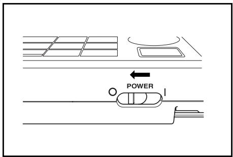
2 Connect the AC adapter connector plug to the AC adapter terminal on the rear of the instrument.
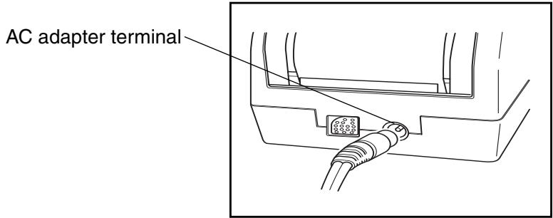
Insert the AC adapter power plug to an AC outlet (100-240 Vac).
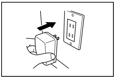
- If the batteries are installed in both measuring head and data processor and the AC adapter is used, the power is supplied by AC adapter.
- If the connected measuring head and data processor are used, the power is supplied from data processor to measuring head.
If the batteries are installed in data processor and the AC adapter is used, the power is supplied by AC adapter. The power is not supplied from measuring head to data processor.
Precautions regarding connecting and disconnecting the measuring head and data processor.
- Before connecting and disconnecting, make sure that the power to both the measuring head and dataprocessor is turned OFF.
- Hold the connector when connecting or disconnecting. Do not bend, pull, or apply undue pressure to the cord, as this may cause it to break.
- When using the measuring head alone or replacing it, some items in the data processor settings may be changed at the connection. See P.64 "Setting Status of Connected Measuring Head and Data Processor" for details on the default values and status during connection of all settings shared by the measuring head and data processor when connected.
- We recommend using the measuring head and the data processor with the same settings.
[Operating Procedure]
1 Make sure the power switches on the measuring head and data processor are OFF (O).
![KONICA CR-410 - [Operating Procedure] - 1](/content/2025/01/172144/images/383451531e47fb2f6eb7ef2c5ac4014766a321bb820788e80dca20baf15c612a.jpg)
![KONICA CR-410 - [Operating Procedure] - 2](/content/2025/01/172144/images/ca19a2a59c7ebd3a78132b8da724dcbeea38cf32339225d57270b427b336e644.jpg)
2 Insert the one side of the RS-232C cable to the RS-232C terminal on the measuring head.
![KONICA CR-410 - [Operating Procedure] - 3](/content/2025/01/172144/images/4afb1c743ae4dba95a59a0e441eec0f4416f62965833bb934527ade478996740.jpg)
RS-232C terminal
3 Insert the other side of the RS-232C cable to the RS-232C terminal on the data processor.
![KONICA CR-410 - [Operating Procedure] - 4](/content/2025/01/172144/images/1b04350206f5a0a3050b12972c0f8801a080009e9dce5855925c20a2d4f86858.jpg)
Note
When removing the RS-232C cable, turn OFF the measuring head and data processor and push the lock release button certainly while removing the cable.
If the lock is not released and remove it by force, the connector may be damaged.
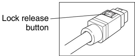
The common default settings and connecting status of connected measuring head and data processor are shown as follows.
- Setting items which are not described below are not changed in spite of connecting status.
(Head: Measuring Head, DP: Data Processor)
| Item | Default | Connecting status(The data of arrow left side overwrites the data of arrow right side) | Remarks | |
| Head | DP | |||
| Illuminant | C | C | DP → Head | The DP data can overwrite the Head data when the instrument is initial settings. |
| White calibration data | 0 | - | Head → DP | The data is not stored in DP (operation only) |
| User calibration Ch | None | - | ||
| Multi-calibration | OFF | - | ||
| Target color data | None | - | Head → DP | The data is not stored in DP (operation only) |
| Selected color difference target color | None | - | ||
| Mesurement data | None | None | - | The Head data can be transferred to DP by optional setting "moving data". |
| Selected color space Screen display | XYZ | XYZ | DP → Head | *When the measuring head is disconnected from the data processor and used, the settings at the time of disconnection remain. |
| Absolute value/color difference | Absolute value/color difference | |||
| Displayed color limit (CMC parameter) | See P.76 | See P.76 | DP → Head | User index only: Head → DP |
| User index | "Initial Setting" | "Initial Setting" | Head → DP | (User index is not initialized by "Initial Settings" of DP.) |
| None | None | |||
| Date & time | Adjustment at shipment | Adjustment at shipment | DP → Head | If backup batteries are dead the setteing becomes 2002/01/01 00:00 (It is not initialized by "Initial Settings" of DP.) |
| Language | English | *English | DP → Head | *(It is not initialized by "Initial Settings" of DP.) |
| Baud rate | 9600 | *19200 | Head → DP | *Baud rate of DP remote mode is fixed at 19200. (It is not initialized by "Initial Settings" of DP.) |
| Protecting data Number of measurements for average | OFFOnce | OFFOnce | DP → Head | |
[Operating Procedure]
1 Set the POWER switch to (I).
- The measurement screen appears after the start-up screen.
Power switch
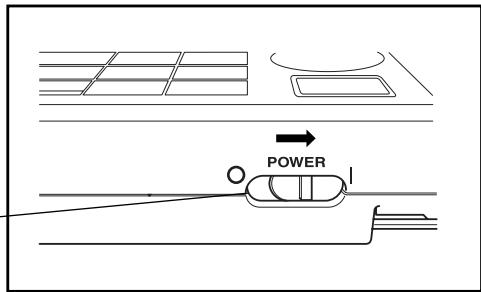
[Operating Procedure]
1 Set the POWER switch to (O).
Power switch
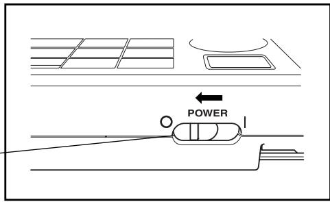
Note
- You do not have to turn the measuring head and data processor ON/OFF in order when they are connected.
The instruments recognize connecting status automatically.
- To turn OFF the power switch, observe the following instructions:
1) Do not turn OFF the data processor power switch immediately after execution of measurement (including calibration and target color measurement for update).
2) Do not turn OFF the data processor power switch when transferring data from the measuring head.
3) Do not turn OFF the measuring head power switch when automatic averaging measurement is in progress with the data processor.
In the above cases 1) and 2), the data processor receives measurement data from the measuring head, and stores the data into the data processor internal memory after necessary processing. If the power switch is turned OFF before completion of data storage, the data may be lost, or incompletely stored. If an incomplete storing condition is detected at the next startup, the data processor may initialize all stored data because it recognizes corruption of stored data. (For initialization, see NOTE in on P.66.) In case of the above 3), the data processor may not accept key entry even after the measuring head is restarted and re-connected. In such a condition, restart the data processor.
The data processor recognizes connecting status to measuring head automatically and can communicate with measuring head after power is ON.
The following screens appear while the data processor reads settings of measuring head.
Reading time depends on number of color difference target color data of measuring head.
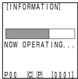
Measuring head is connected
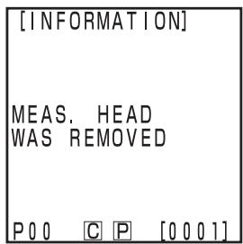
Measuring head is removed
Measuring head
"DP MODE" is displayed in measuring head LCD.
Only measurement button functions.
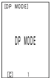
Data processor is connected
- Power save mode will be activated if the measurement button and operation keys are not operated for more than three minutes. When in power save, the power save screen appears. Power save mode can be disengaged by pressing any of the operating keys or the measurement button.
In measuring with the timer, remote mode or printing, the auto power save function will not operate.
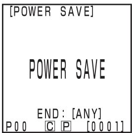

If the power-saving function is activated when an error screen is displayed, the error screen is retained without showing the power-saving mode. In this case, pressing any operation key or measurement button cancels the power-saving mode, and displays the error screen. (The screen indication does not change.) If the operation key is pressed again, the display returns to the original screen.
Data and settings in the instrument are automatically stored.
The memory is protected if the batteries are in the instrument or it is plugged in to the AC adapter and the power is ON because of power supply to the memory. The instrument also has special internal memory backup batteries, so as long as the batteries are at full charge, the contents of memory are protected for up to 10 months even if the batteries in the measuring head are removed or the AC adapter is not used. (A full charge is achieved when the AC adapter is connected continuously for 20 hours from when the power is turned on.)
Note
If the data processor is left for a long period with the power switch turned OFF, electricity is discharged from the memory backup battery, disabling data backup. In this case, data stored in the memory will be corrupted. If the data processor is started in this condition, the data processor initializes all data stored in the memory. In addition to all items described in "Initial Setting" on P.76, the following items will be initialized.
1) Date/time will be initialized to "2002/01/01 00:00".
2) The language setting will be initialized to "ENGLISH".
Measuring Head
See P.27 "Turning the Power ON and OFF" for details on the measuring head.
Inserting the Roll Paper
Notes on Use
The data processor has a thermal printer which does not require an ink ribbon. Printed data may become difficult to read because of the way the paper has been stored. Use new roll paper whenever possible. We recommend you copy any data for long-term storage immediately after it has been printed.
[Operating Procedure]
1 Cut the edge of the roll paper as shown in the figure and pull out.
![KONICA CR-410 - [Operating Procedure] - 1](/content/2025/01/172144/images/627f26aa499365cd8c88c01bec6e637c118bbdd7b21373720a305a23eee480bd.jpg)
2 Open the paper chamber cover.
3 Slide the roll paper cut holder in the direction of the arrow and then remove it.
Roll paper cut holder
![KONICA CR-410 - [Operating Procedure] - 2](/content/2025/01/172144/images/8180d12146bce20e67b37b90a61ab157bd1109e2d92c5d5e27544643ca306378.jpg)
4 Move the paper lock lever to OPEN.
Paper lock lever
![KONICA CR-410 - [Operating Procedure] - 3](/content/2025/01/172144/images/ae12e33e623c62af60aa71d30b24ec37d6ec6984bdb6a61051cca933f7e42d32.jpg)
5 Insert the edge of roll paper into the slot as shown in the figure.

Inner surface of roll paper is up side.
Inserting the paper upside down results in nothing printed.
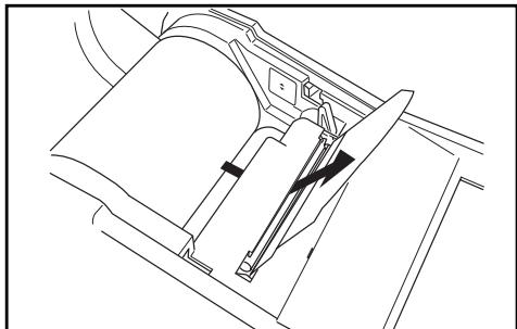
6 Pull out the edge of the roll paper by 4-5 cm manually.
7 Move the paper lock lever to CLOSE.

Do not pull out the roll paper after locking, as this may cause a malfunction.
Paper lock lever
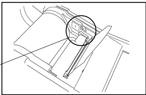
8 Lead the roll paper through the roll paper cut holder and then set the roll paper cut holder to the instrument in the direction of the arrow.
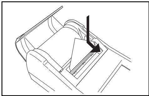
9 Put the roll paper into the paper chamber, and close the cover.

Do not print without the roll paper, as this may cause a malfunction.
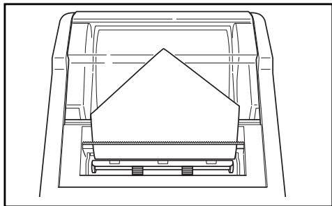
Notes on Use
- Do not place soluble adhesives, adhesive tape, etc. on the side of the paper to be printed on.
- Do not place in direct contact with plastic office supplies for long periods of time.
- Do not handle with wet or sweaty hands.
- Do not hit with hard objects.
- When writing titles, etc., use fountain pens, pencils, or water-based pens. Do not use oil-based pens.
Adjust the brightness of the LCD display to the most appropriate level.
[Operating Procedure]
1 Turn the display contrast adjustment dial on the right side of the data processor so that the display is the most appropriate level.
- Turning it towards ① makes the display darker and towards ② makes it lighter.
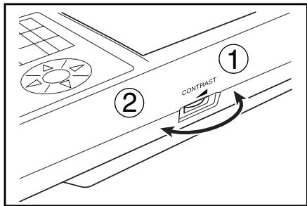
Note
Setting this with low batteries may make the display difficult to see after measurement. Turn the dial so that the display is the most appropriate level. (Replace the batteries as soon as possible.)
Attaching the shoulder strap
Only customers who purchased the optional shoulder strap should refer to this. The shoulder strap is attached to the instrument as follows.
[Operating Procedure]
1 Pass the strap through the shoulder strap attachment.
![KONICA CR-410 - [Operating Procedure] - 1](/content/2025/01/172144/images/c89029cb7195927099e3567709fa257498a083a22fcd77aaaf928332cb5dc222.jpg)
2 Pass the strap back through, as shown in the figure at right.
![KONICA CR-410 - [Operating Procedure] - 2](/content/2025/01/172144/images/9dbac5f83bd83bab45dc82809687e987c0f3085bf1b17ce8142775e8711ccfea.jpg)
The instrument allows the user to select from six language modes. 1) Japanese 2) English 3) German 4) French 5) Spanish 6) Italian
If the language settings in the measuring head and the data processor are different, the setting for the data processor is reflected to the measuring head.
![KONICA CR-410 - [Operating Procedure] - 3](/content/2025/01/172144/images/5a9fc8bb6b8fbc6f8086a81ea0fc31d619c4b6ad763c2e255cfd26f0a0778fa5.jpg)
[Operating Procedure]
1 Turn the power ON (I) while pressing the Enter key at the same time. Measure Enter
- The language selection screen appears.
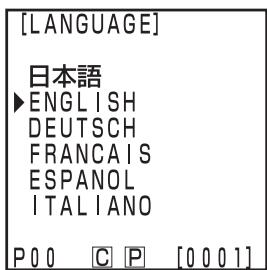
Language selection screen
2 Select the language using the key.
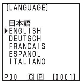
3 Press the Enter key Measure Enter
- Once selection of language is complete, the start-up screen appears.
When shipped from the factory, the language mode is set to English. If another language is selected and the internal memory backup battery dies, the language mode will revert to English. The memory backup battery will die if the instrument is not supplied with power for ten months.
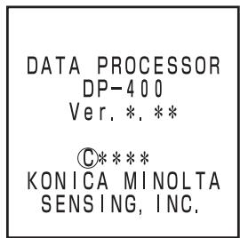
Start-up screen
This function only works when the measuring head is connected.
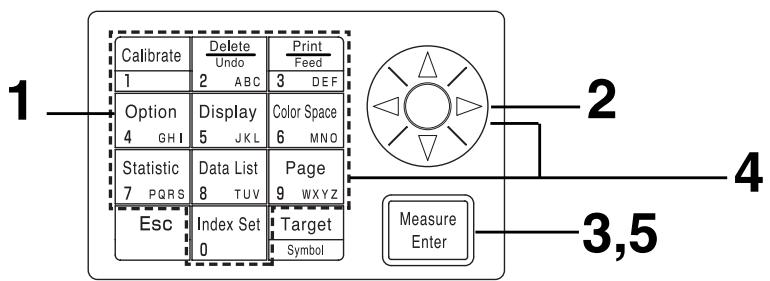
[Operating Procedure]
1 Press the Option key 4 0H1 while in the measurement screen.
- The option screen appears.
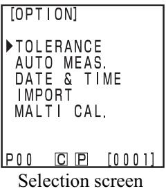
2 Select "DATA & TIME" using the key.
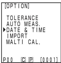
3 Press the Measure/Enter key Measure Enter
- The date & time screen is displayed.
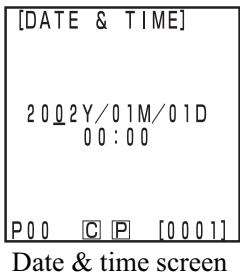
4 Set the current date and time using the key and the numeric pad.
- This example shows how to enter the date and time for October 02, 2002, 14:35.
- Entry is done in 24-hour time.
- A calendar up to 2099 is built in, so non-existent dates and times cannot be entered.
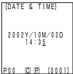
5 Once the date and time are entered, press the Measure/Enter key.
- The display returns to the measurement screen.
The instrument has the following nine basic settings.
| Item | Settings | Default | Description |
| 1) Printer (Automatic printing) | OFF/ON | ON | This sets whether or not to automatically print data after measurement.Print/Paper Feed key still works, regardless of this setting. |
| 2) Printing color spaces | OFF/ON | OFF | This sets whether or not to print all color spaces selected in the display limit.(This does not include statistical operations.) |
| 3) Data Protection | OFF/ON | OFF | This sets whether or not to protect existing data in the event that the number of stored data sets exceeds 2000.If data protection is OFF, old data is overwritten.If data protection is ON, the 2001st data is prevented. |
| 4) Number of measurement for auto. average | 1 - 30 measurements | 1 measurement | This sets the number of measurements for automatic average.It can be set to between 1 and 30 measurements. |
| 5) Illuminant | C/D65 | C | This sets the illuminant to C or D65.The illuminant cannot be changed during measurement.Set illuminant again to change an illuminant after initial setting (See P.76). Some color spaces may not be able to be displayed depending on the illuminant setting.(See P.79 “Color Space and Chang-ing the Display”). An error message is displayed and connection is prevented if different illuminants are set for the measuring head and the data processor. |
| 6) Back light | OFF/ON | OFF | This sets the back light ON and OFF.The back light automatically goes OFF 30 seconds after key operation, even if it is set to ON. |
| 7) Buzzer | OFF/ON | ON | This sets the buzzer ON and OFF.The following buzzer sounds are emitted when set to ON.Key reception, error, judgment, settings complete. |
| 8) Displayed color limit | XYZ, Yxy,L*a*b*,Hunter Lab,L*C*h, Munsell(illuminant C only), CMC (l:c), CIE1994, Lab99,LCh99, CIE2000,CIE WI/Tw(illuminant D65only), WI ASTM E313 (illuminant C only), YI ASTM D1925 (illuminant C only), YI ASTM E313 (illuminant C only)*User index | XYZ, Yxy,L*a*b*,Hunter Lab,L*C*h,Munsell | Select the color space to be displayed.The color space currently displayed in the measurement screen cannot be turned OFF.It is not possible to turn OFF all color spaces.Some color spaces cannot be selected depending on the illuminant setting. |
| 9) Remote mode | This mode is for data output to connected PC. |
*When set to the measuring head (See P.127 "UserID").
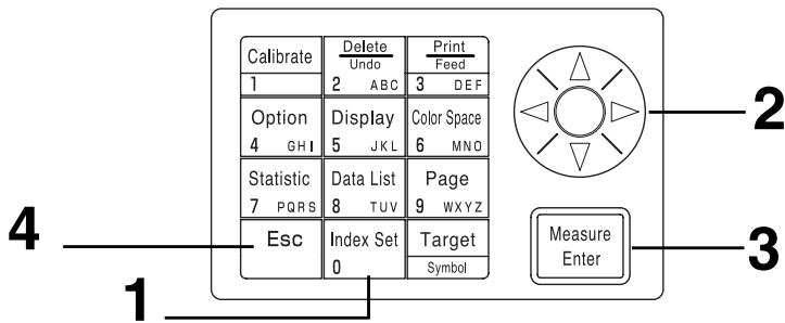
[Operating Procedure]
Press the Index Set key 0 while in the measurement screen.
- The index set screen is displayed.
2 Select the item to set using the key.
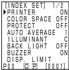
(Page 1 of 2)
3 Press the Measure/Enter key to change each setting.
- Pressing the Measure/Enter key changes the setting value in the table on P.72 for each setting.
- See P.74 "Setting the Displayed Color Limit" for details on the displayed color limit.
- The page can be changed by pressing the key.
- The page can be changed by keeping the key pressed.
- Pressing the Measure/Enter key in remote mode changes to the PC connection mode. (See P.129 "Changing to Remote Mode".)

(Page 2 of 2)
4 Once the basic settings are complete, press the Escape key Esc to return to the measurement screen.
This setting selects the color space to be displayed.
See P.79 "Color Space and Changing the Display" and P.80 "Color Space and Color Difference Setting" for details on the setting conditions.
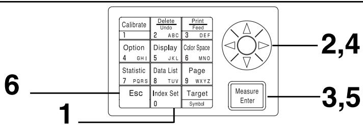
[Operating Procedure]
Press the Index Set key while in the measurement screen.
- The item setting screen will appear.
2 Select "DISP. LIMIT" using the key.
3 Press the Measure/Enter key Measure Enter
- The displayed color limit screen appears.
4 Select a color space using the key.
Press the Measure/Enter key to turn ON and OFF each color space.
- The color space being displayed in the measurement screen cannot be turned OFF.
See P.75 "CMC Parameter Setting" for details on CMC parameter setting.
- The page can be changed by pressing the key.
- The page can be changed by keeping the _Y^X key pressed.
- This may be three pages long if a user index is registered in connected measuring head.
(See P.127 "UserID".)
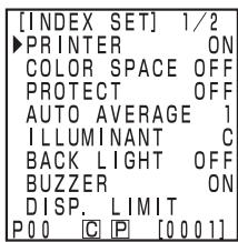
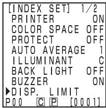
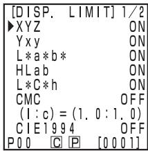
Displayed color limit screen (Page 1 of 2)
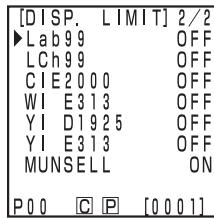
Displayed color limit screen (Page 2 of 2)
6 Once the settings are complete, press the Escape key Esc to return to the measurement screen.
The CMC parameter can be set anywhere in the range of 0.1 to 9.9.
See P.79 "Color Space and Changing the Display" and P.80 "Color Space and Color Difference Setting" for details on setting conditions.
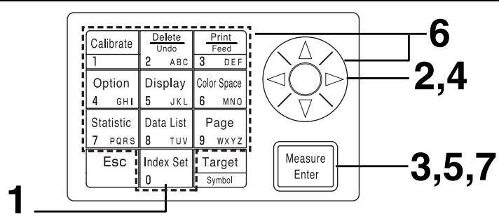
[Operating Procedure]
After steps 1 to 3 on P.74 "Setting a Displayed Color Limit", perform following steps below.
4 Select the CMC parameter settings using the key.
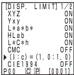
Displayed color limit screen (Page 1 of 2)
5 Press the Measure/Enter key Measure Enter
- The cursor is displayed below the CMC parameter setting.
6 Set the CMC parameter using the key or the numeric pad.
Input range: 0.1 - 9.9
7 Once the setting is complete, press the Measure/Enter key to return to color space selection in the displayed color limit screen.
- Pressing the Escape key Esc returns to the previous screen.
Initialize the settings to return to factory preset.

Date and time are not changed.
- "Measurement data" stored in the instrument as well as "white calibration data", "user calibration data", and "color difference target color data" stored in the connected measuring head are all deleted.
- When the measuring head is connected, the initialization is also performed on the measuring head.
The items set are as follows.
| Item | Default |
| 1) Data | Delete all (calibration data, measurement data, target color data) |
| 2) Measurement screen display format | Absolute value |
| 3) Printer | ON |
| 4) Print color space | OFF |
| 5) Data protection | OFF |
| 6) Number of means. for average | Once |
| 7) Multi-calibration | Ch00 (white calibration plate) |
| 8) Illuminant | C |
| 9) Displayed color limit | XYZ, Yxy, L*a*b*, Hunter Lab, L*C*h, Munsell |
| 10) CMC parameter | 1.0:1.0 |
| 11) Back light | OFF |
| 12) Buzzer | ON |
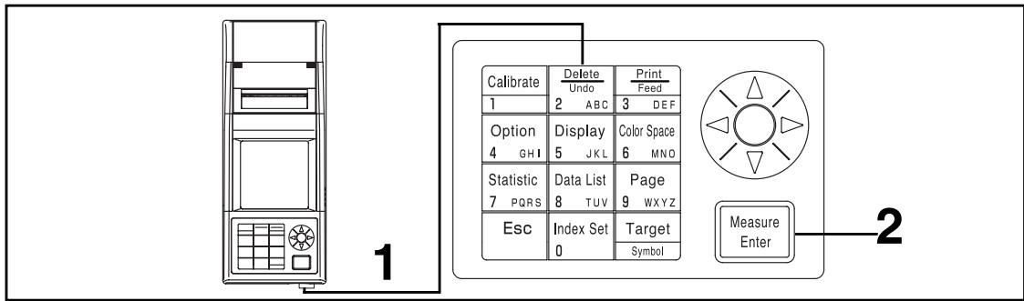
Operating Procedure
1 Turn the power ON while pressing the Delete/Undo key 2 ABC
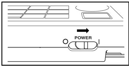
- The initial setting screen appears after the operating screen.
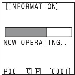
Operating screen
2 Press the Measure/Enter key to start the initialization.
- If the power is already ON, turn it OFF, wait a few seconds, and then proceed with the initialization.
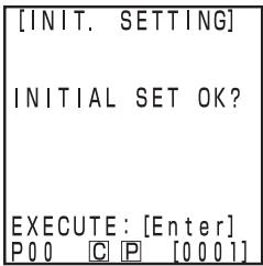
Initial setting screen
Using this instrument changes the color space as below.
(Color spaces) XYZ, Yxy, L*a*b*, Hunter Lab, L*C*h, Munsell (illuminant C only), CMC(l:c), CIE1994, Lab 99, LCh99, CIE2000, CIE WI/Tw (illuminant D_65 only), WI ASTM E313 (illuminant C only), YI ASTM D1925 (illuminant C only), YI ASTM E313 (illuminant C only) * User index
- The displayed color space can be selected depending on the displayed color limit. (See P.72 "Basic Setting".)
- Up to 6 data can be displayed if a user index is registered. (See P.127 "UserID")
See P.79 "Color Space and Changing the Display" and P.80 "Color Space and Color Difference Setting" for details on the setting conditions for the color space.
[Operating Procedure]
Press the Color Space key to select the color space.
- The display changes every time the key is pressed.
[Absolute value/color difference for color difference measurement (example)]
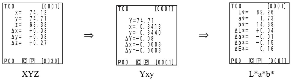
↑
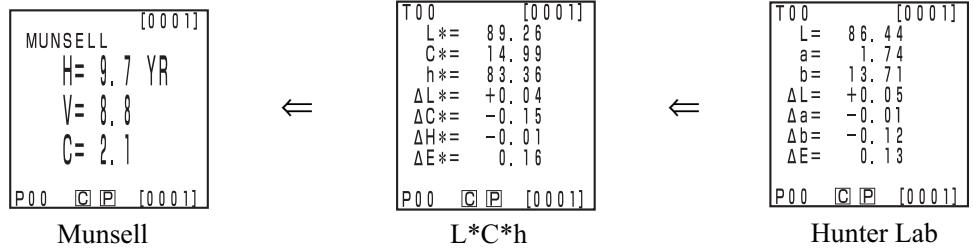
[Setting conditions]
- The color difference target color is set.
- Absolute value/color difference display is selected by pressing the Change Display key [Display].
- 6 color spacaces shown above are selected by setting displayed color limit.
Setting conditions of color space and symbol/illuminant/default of displayed color limit/changing display are shown as follows.
There are restrictions depending on selected color space in the following table.
- In chapter 3 Data Processor, all displays except for User index in the table function.
(O: Valid, X: Invalid)
| Color space | Symbol | Illuminant | Displayed color limit | Changing display | |||||||
| Absolute value | Color Difference | C | D65 | C | D65 | Absolute value | Color difference | Absolute value/color difference | Judgement | Color differ-ence graph*3 | |
| XYZ | X | ΔX | O | O | ON | ON | O | O | O | O | O |
| Y | ΔY | ||||||||||
| Z | ΔZ | ||||||||||
| Yxy | Y | ΔY | O | O | ON | ON | O | O | O | O | O |
| x | Δx | ||||||||||
| y | Δy | ||||||||||
| L*a*b* | L* | ΔL* | O | O | ON | ON | O | O | O | O | O |
| a* | Δa* | ||||||||||
| b* | Δb* | ||||||||||
| ΔE* | ΔE* | ||||||||||
| Hunter Lab | L | ΔL | O | O | ON | ON | O | O | O | O | O |
| a | Δa | ||||||||||
| b | Δb | ||||||||||
| ΔE | ΔE | ||||||||||
| L*C*h | L* | ΔL* | O | O | ON | ON | O | O | O | O*1 | O*1 |
| C* | ΔC* | ||||||||||
| h | ΔH* | ||||||||||
| ΔE* | ΔE* | ||||||||||
| CMC (l:c) | L* | ΔLc | O | O | OFF(1.0:1.0) | OFF(1.0:1.0) | O | O | O | O*1 | O*1 |
| C* | ΔCc | ||||||||||
| h | ΔHc | ||||||||||
| CMC | CMC | ||||||||||
| CIE1994 | L* | ΔL94 | O | O | OFF | OFF | O | O | O | O*1 | O*1 |
| C* | ΔC94 | ||||||||||
| h | ΔH94 | ||||||||||
| ΔE94 | ΔE94 | ||||||||||
| Lab99 | L99 | ΔL99 | O | O | OFF | OFF | O | O | O | O | O |
| a99 | Δa99 | ||||||||||
| b99 | Δb99 | ||||||||||
| ΔE99 | ΔE99 | ||||||||||
| LCh99 | L99 | ΔL99 | O | O | OFF | OFF | O | O | O | O*2 | O*2 |
| C99 | ΔC99 | ||||||||||
| h99 | ΔH99 | ||||||||||
| ΔE99 | ΔE99 | ||||||||||
| CIE2000 | L* | ΔL00 | O | O | OFF | OFF | O | O | O | O*1 | O*1 |
| C* | ΔC00 | ||||||||||
| h | ΔH00 | ||||||||||
| ΔE00 | ΔE00 | ||||||||||
| WI E313 | WI | ΔWI | O | X | OFF | - | O | O | O | O | X(Absolutevalue/colordifference) |
| YI D1925 | YI | ΔYI | O | X | OFF | - | O | O | O | O | X(Absolutevalue/colordifference) |
| YI E313 | YI | ΔYI | O | X | OFF | - | O | O | O | O | X(Absolutevalue/colordifference) |
| Munsell | H | - | O | X | ON | - | O | X(Absolutevalue) | X(Absolutevalue) | X(Absolutevalue) | X(Absolutevalue) |
| V | - | ||||||||||
| C | - | ||||||||||
| CIE WI/Tw | WI | ΔWI | X | O | - | OFF | O | O | O | O | X(Absolutevalue/colordifference) |
| Tw | ΔTw | ||||||||||
| User index*4 | Up to 9 characters | O | O | ON(At registration) | ON(At registration) | O | X(Absolutevalue) | X(Absolutevalue) | X(Absolutevalue) | X(Absolutevalue) | |
1: Graph display and judgement at L^ , a^ , and b^
2: Graph display and judgement at ΔL99, Δa99, and Δb99
3: Only screen display of data processor
*4: The registration by only PC is available.
Setting conditions of color space and symbol/color difference target color/color difference tolerance types are shown as follows.
There are restrictions in the following table depending on selected color space.
- In chapter 3 Data Processor, all displays except for User index in the table function.
(O: Valid, X: Invalid)
| Color space | Symbol | Color difference target color | Color difference tolerance type | |||||
| Absolute value | Color Difference | Measurement input | Numeric input | Elliptical tolerance | Box-type tolerance | ΔE | Box-type tolerance and ΔE | |
| XYZ | X | ΔX | O | O | O | O | O | O |
| Y | ΔY | (ΔE*) | (ΔE*) | |||||
| Z | ΔZ | |||||||
| Yxy | Y | ΔY | O | O | O | O | O | O |
| x | Δx | (ΔE*) | (ΔE*) | |||||
| y | Δy | |||||||
| L*a*b* | L* | ΔL* | O | O | O | O | O | O |
| a* | Δa* | |||||||
| b* | Δb* | |||||||
| ΔE* | ||||||||
| Hunter Lab | L | ΔL | O | O | O | O | O | O |
| a | Δa | |||||||
| b | Δb | |||||||
| ΔE | ||||||||
| L*C*h | L* | ΔL* | O | X | O*1 | O*1 | O | O*1 |
| C* | ΔC* | |||||||
| h | ΔH* | |||||||
| ΔE* | ||||||||
| CMC (l:c) | L* | ΔLc | O | X | O*1 | O*1 | O | O*1 |
| C* | ΔCc | |||||||
| h | ΔHc | |||||||
| CMC | ||||||||
| CIE1994 | L* | ΔL94 | O | X | O*1 | O*1 | O | O*1 |
| C* | ΔC94 | |||||||
| h | ΔH94 | |||||||
| ΔE94 | ||||||||
| Lab99 | L99 | ΔL99 | O | O | O | O | O | O |
| a99 | Δa99 | |||||||
| b99 | Δb99 | |||||||
| ΔE99 | ||||||||
| LCh99 | L99 | ΔL99 | O | X | O*2 | O*2 | O | O*2 |
| C99 | ΔC99 | |||||||
| h99 | ΔH99 | |||||||
| ΔE99 | ||||||||
| CIE2000 | L* | ΔL00 | O | X | O*1 | O*1 | O | O*1 |
| C* | ΔC00 | |||||||
| h | ΔH00 | |||||||
| ΔE00 | ||||||||
| WI E313 | WI | ΔWI | O | X | X | O | X | X |
| YI D1925 | YI | ΔYI | O | X | X | O | X | X |
| YI E313 | YI | ΔYI | O | X | X | O | X | X |
| Munsell | H | - | X | X | X | X | X | X |
| V | - | |||||||
| C | - | |||||||
| CIE WI/Tw | WI | ΔWI | O | X | X | O | X | X |
| Tw | ΔTw | |||||||
| User index *4 | Up to 9 characters | O*3 | O*3 | X | X | X | X | |
1: Input color difference tolerance at L^ , a^ , and b^
2: Input color difference tolerance at ΔL99, Δa99, and Δb99
3: Input at XYZ color space
*4: The registration by only PC is available.
The basic screen layout is shown below.
The measurement results can be changed as needed.
[Operating Procedure]
Press the Change Display key 5~x~ while in the measurement screen to change the display for your use.
- The display changes every time the key is pressed.
[Setting conditions]
- The color difference target color is set.
- L^a^b^* is selected by pressing the Color Space key [Color Space]
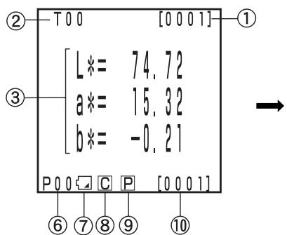
Absolute value
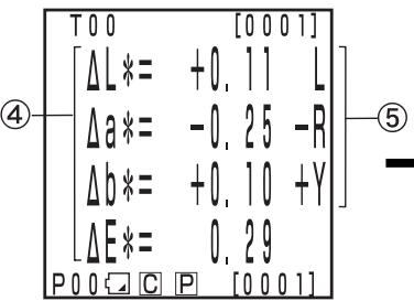
Color difference
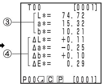
Absolute value/ color difference
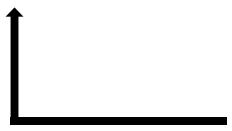
Judgment
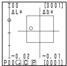
Color different graph
- The display for "color difference graph" and "judgment" are example screens with color difference tolerance set. To set the color difference tolerance, see P.116 "Setting the Color Difference Tolerance"
- Depending on the color space, display change may be restricted. (See P.79 "Color Space and Changing the Display".)
Information display
1) Current measurement data number (per page)
2) Color difference target No. and color name for the displayed measurement data.
Measurement value display
3) Absolute measurement data
4) Color difference measurement data
5) Color difference sensuous display
L* direction: "L" or "D" (Lighter or Darker)
a direction: “+R” or “-R” or “G” or “-G” (±Red or ±Green)
direction: “+Y” or “-Y” or “B” or “-B” (±Yellow or ±Blue)
Icon display
6) Page number
When performing timer measurement, [ ] is displayed.
7) Battery
The battery power is displayed in three levels. The battery level display is not shown when the AC adaptor is connected.
[No display] (when there is sufficient power or when the AC adapter is being used.)

(Low Battery):
- Measurement can still be done for a while even if this is displayed.
We, however, recommend replacing new batteries as soon as possible, or using AC adapter.

(Battery Out):
- When this is displayed, all operation can no longer be done. We recommend replacing new batteries quickly, or using AC adapter.
8) Illuminant
C(C): indicates CIE standard illuminant C.
D (D65) : indicates CIE standard ental illuminant D65
9) Printer
P (ON): after measurement, automatic printing data is ON.
[No display] (OFF): after measurement, automatic printing data is OFF.
10) Total number of stored data: displays the total number of pages.
See P.72 "Basic Setting" for details on 8), 9), and 10).
Color difference graph
The display is as shown in the figure at right when no color difference tolerance is set.
Setting the color difference tolerance (see P.116 "Setting the Color Difference Tolerance") makes the following color difference graph display is displayed.
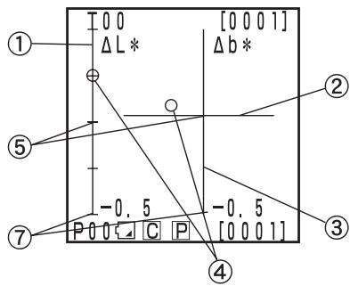
1) L^ axis
2) a^ axis
3) b^ axis
4) Measurement point
5) Color difference target color measurement point
6) Displaying a box-type color difference tolerance
7) Scale on the L^ and b^* axes (Indicates a value at the minus end point of each axis. The scale setting will be automatically changed.)
8) Displaying a elliptical color difference tolerance
[Setting conditions]
O PASS: This is displayed when the value is within the color difference tolerance.
WARN: This is displayed when value is within the color difference tolerance, but exceeds the warning level.
X FAIL: This is displayed when the value exceeds the color difference tolerance.
- The color difference target color is set.
- L*a*b* is selected by pressing the Color Space key
The color difference graph is selected by pressing the Change Display key [Display S.].
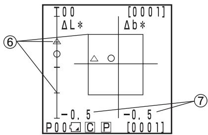
Box-type color difference tolerance setting
Within the color difference tolerance
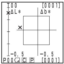
Out of the color difference tolerance
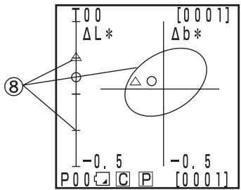
Elliptical color difference tolerance setting
Within the color difference tolerance
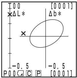
Out of the color difference tolerance
Judgment
The display is as shown in the figure at right when no color difference tolerance is set.
Setting the color difference tolerance (see P.116 "Setting the Color Difference Tolerance") makes the following judgement is displayed.
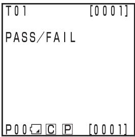
O PASS: This is displayed when the value is within the color difference tolerance.
WARN: This is displayed when value is within the color difference tolerance, but exceeds the warning level.
X FAIL: This is displayed when the value exceeds the color difference tolerance.

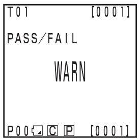
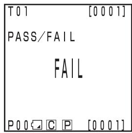
Basic Operating Procedure Flow
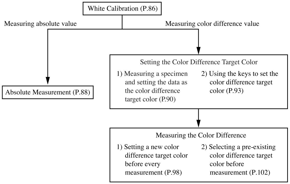
When using the instrument for long periods of time, the displayed value may change depending on changes in the environment. Therefore, in order to achieve accurate measurements, we recommend that white calibration is done regularly using the white calibration plate. White calibration should also be done before measuring after a long time has passed since the instrument was last used.
Note
White calibration should be done under the same temperature conditions as measurement.
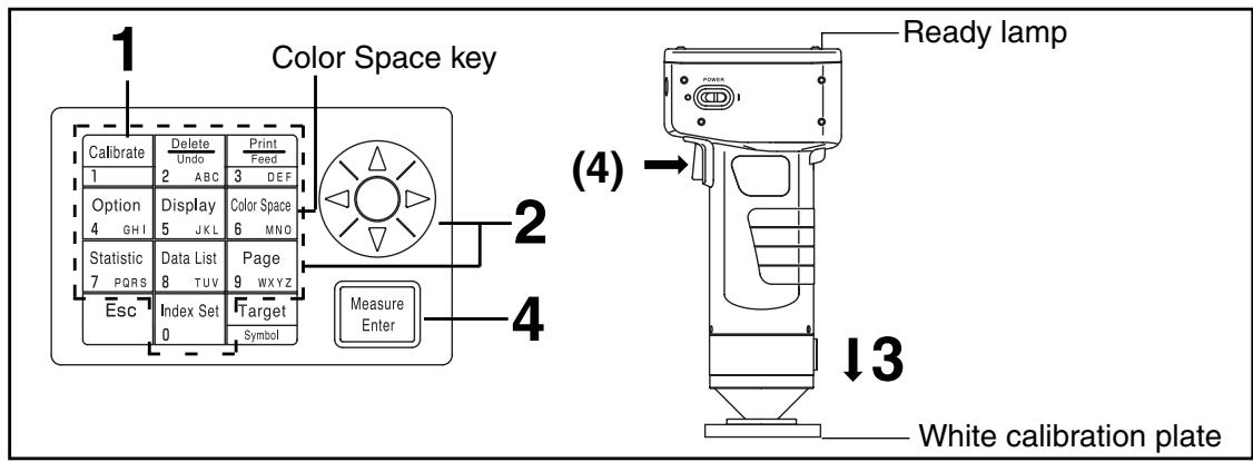
[Operating Procedure]
1 Press the Calibration key Calibrate while in the measurement screen.
- The white calibration screen appears.
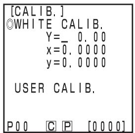
No white calibration data has been set.
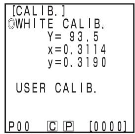
White calibration data has been set.
2 Set the calibration data listed on the back of the white calibration plate cover using the key and the numeric pad.
- The cursor moves automatically to the next position when setting data using the numeric pad.
- Use the to move the cursor to make corrections.
- Go to step 3, if white calibration data has already been set.
[Example]
- Illuminants C
Y = 93.5 x = 0.3114
y=0.3190
- Illuminants D_65
Y = 93.5 x = 0.3140
y=0.3318
Note
After the initial setting is complete, the illuminant is set to C , so set the data for C . When using D_65 , change the setting to "D65" before calibration as described in steps 1 to 4 on P.72 "Basic Setting 5) Illuminant". After this, return to this page and set the data for D_65 .
- See P.76 "Initial Setting" and P.72 if illuminant is changed after calibration.
3 Place the measuring head vertically above the middle of the white calibration plate.
Note
The white calibration plate is placed near the center. Use the center area when white calibrating.
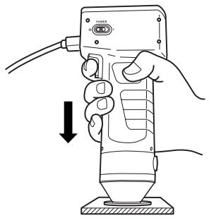
Press the Measure/Enter key (or measurement button on the measuring head) after making sure the ready lamp is ON.
- Calibration is complete after the lamp flashes three times. Complete sound beeps and the display returns to the measurement screen.
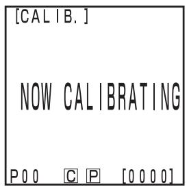
The illuminant lamp flashes three times.

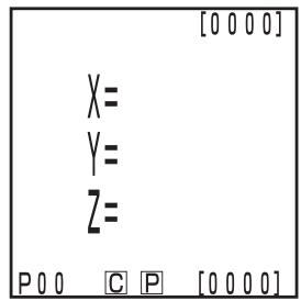
Measurement screen
Note
- Do not move the measuring head during calibration.
- If selected in user calibration, select "white calibration plate" following steps 1 to 4 on P.137 "Setting the Manual Select Calibration" to set to the white calibration.
With this, white calibration is finished.
When measuring the chroma values (absolute values), perform P.88 "Absolute Measurement". To measure the color difference between a color difference target color and a specimen, perform P.90 "Setting the Color Difference Target Color" and P.98 "Measuring the Color Difference".
This instrument can measure reflected object color with the color spaces, XYZ, Yxy, Lab, Hunter Lab, LC*h, Munsell, and others. (See P.78 "Selecting the Color Space" for details)
Note
Mesurement should be done under the same temperature conditions as calibration.
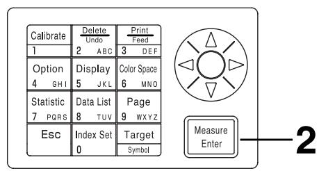
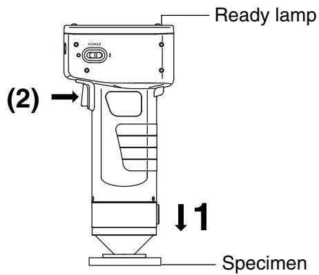
INote
Before Mesurement
- Select the color space and screen for your use.
See P.78 "Selecting the Color Space", and P.81 "Screen Display and Changing the Display" for details.
[Operating Procedure]
1 Place the measuring head vertically above the specimen while in the measurement screen.
![KONICA CR-410 - [Operating Procedure] - 1](/content/2025/01/172144/images/d66e44b10ee6f766b20ee21e1b429d3f043d843fccd92573fa8812037a2a4e73.jpg)
Press the Measure/Enter key (or the measurement button on the measuring head) after making sure the ready lamp is ON.
- Measurement is done and the data is displayed. If the printer is set to ON on the index set screen, the data is printed out.
Note
Do not move the measuring head during measurement.
Note
After Mesurement
- Pressing the Color Space key [Color Space] converts the measurement data to other color spaces. (See P.78 "Selecting the Color Space")
- Pressing the Color Space key Color Space 5_NWC changes the screen display. (See P.81 "Screen Display and Changing the Display")
Note
- Measured data is automatically stored.
If you do not wish to store data, press the Delete/Undo key [Delete] to delete the latest data.
If you mistakenly delete data you wished to keep, press the Delete/Undo key again and the latest deleted data is restored.
Note, however, that if new measurement data replaces the latest deleted data, that data is no longer restorable, since the new data is stored in its place.
-
Up to 2000 measurement data sets can be stored.
-
When data protection is set to OFF and data quantity exceeds 2000 items, the oldest page that contains measurement data will be deleted, and a data storing area will be secured. (If the page to be deleted is page 0, the relevant page remains, but the measurement data on this page will be deleted.) If there is no page that contains measurement data other than the current page, the oldest data on the current page will be overwritten.
- When data protection is set to ON, a measurement error occurs, and the "Data Memory Full" error message appears.
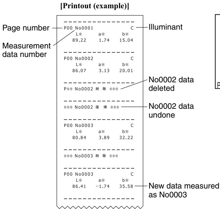
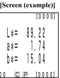
[Setting conditions] Select L^a^b^* color space and absolute display
- Press the Print/Paper Feed key 3Cost anytime you want to print out the data displayed in the LCD.
The instrument can measure the color difference between the color difference target color and a specimen using color spaces, (XYZ) , (Yxy) , (L^a^b^) , Hunter Lab, (L^C^*H) , and others. (See P.78 "Selecting the Color Space" for details.)
Before measuring color difference, you must set the color difference target color in the measuring head. 100 color difference target colors can be set to nos. T00 to 99.
The color difference target color number can be changed to a name for the sake of convenience.
The color difference target color number can be set independently of the page function (P.105).
Note
Setting color difference target colors should be done under the same temperature conditions as calibration and measurement.
There are two ways to set the color difference target color.
1) Measuring a specimen and setting the data as the color difference target color
2) Using the keys to set the color difference target color
1) Measuring a specimen and setting the data as the color difference target color
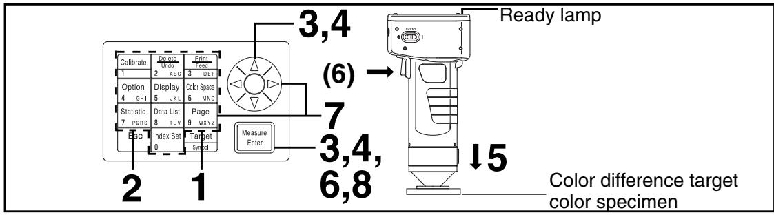
Note
Before Measurement
- Select the color space and screen for your use.
See P.78 "Selecting the Color Space", and P.81 "Screen Display and Changing the Display" for details.
Operating Procedure
1 Press the Target Color key while in the measurement screen.
- The color difference target color setting screen appears.
Press the Print key to print the target value.
Color difference target color name
[TARGET]
TARGET VALUE
1*= 7472
a 一 = + 15.32
b*=+ 10.2]
TARGET NAME [A]
TOO
DISP. LIST: [Esc] P00 C P [0001]
Color difference target color is set to T00.
- The first color difference target color is set to T00. (Target color name T00 can be changed.)
- To set the color difference target color to the currently selected color difference target color number, go to step 6.
Press the Escape key Esc.
The color difference target color list screen appears.
3 Select the color difference target color name using the key and press the Measure/Enter key.
-
If "NEW" is selected, the color difference target color setting screen appears, so go to step 5.
-
If any color difference target color except for "NEW" is selected, the Edit/Change selection screen appears.
-
Edit: edits the selected target color.
- Change: changes the currently selected target color to a newly selected target color and return to the measurement screen.
4 Select "EDIT" using the key and press the Measure/Enter key.
The color difference target color edit screen appears.
Press the Print key to print the target value.
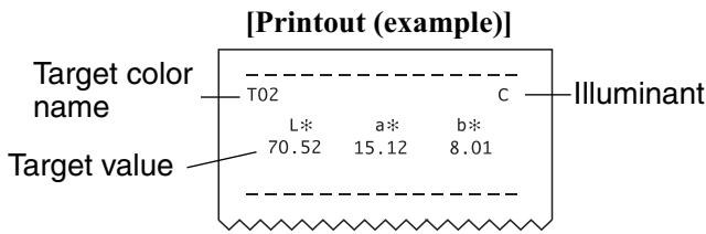
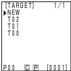
List screen
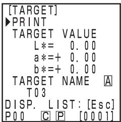
"NEW" is selected.
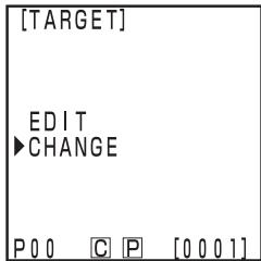
Except for "NEW" is selected.
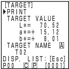
Edit screen
5 Place the measuring head vertically above the color difference target color specimen.
6 Press the Measure/Enter key (or the measurement button on the measuring head) after making sure the ready lamp is ON.
- A new color difference target color is set.
- When not setting a new color difference target color, measuring overwrites the color difference target color data.

Do not move the measuring head during measurement.
7 Once measurement is complete, select "TARGET NAME" using the key and set the color difference target color name using the key and the numeric pad.
- If no color difference target color name is to be selected, proceed to step 8.
- Select "Print" using the key, and then press the Print key to print the target value.
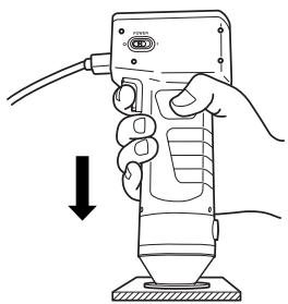
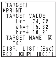
Setting screen
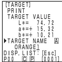
Setting the color difference target color name (example)
(How to set the color difference target color name)
1) Select input mode using the key.
- The input modes change in the following order: upper case Latin letters lower case Latin letters numbers.
2) Move the cursor using the key and input the color difference target color name using the numeric pad.
- The name is up to 9 characters (see P.20 "As input keys" for details.)
8 Once settings are complete, press the Measure/Enter key.
- Settings are complete, complete sound beeps and the display returns to the measurement screen.
Settings are now finished. Other color difference target color numbers can be set by repeating the above procedure.
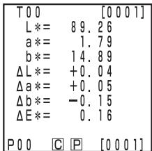
Measurement screen
2) Using the keys to set the color difference target color
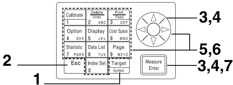
Note
Before Mesurement
- Select the color space and screen for your use.
See P.78 "Selecting the Color Space", and P.81 "Screen Display and Changing the Display" for details.
Operating Procedure
1 Press the Target Color key while in measurement screen.
- The color difference target color setting screen appears.
- Press the Print key to print the target value.
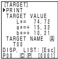
Color difference target color is set to T00.
- The first color difference target color is set to T00. (Target color name T00 can be changed.)
- To set the color difference target color to the currently selected color difference target color number, go to step 6.
Press the Escape key Esc.
- The color difference target color list screen appears.
3 Select the color difference target color name using the key and press the Measure/Enter key Measure Enter
-
If "NEW" is selected, the color difference target color setting screen appears, so go to step 5.
-
If any color difference target color except for "NEW" is selected, the Edit/Change selection screen appears.
-
Edit: edits the selected target color.
- Change: changes the currently selected target color to a newly selected target color and return to the measurement screen.
4 Select "EDIT" using the key and press the Measure/Enter key.
- The color difference target color edit screen appears.
- Press the Print key to print the target value.
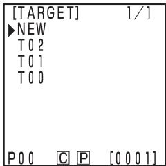
List screen
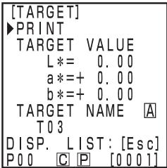
"NEW" is selected.
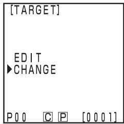
Except for "NEW" is selected.
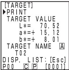
Edit screen
5 Select "TARGET VALUE" using the key, and set the color difference target color data using the key and numeric pad.
Input range: 0.01 ≤ X, Y, Z ≤ 160
[Example]
Setting L^ = 60.72 , a^ = +10.32 , and b^* = +12.21 to color difference target color number T00 should be input as right.
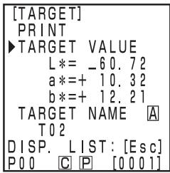
Setting screen
Note
For L^a^b^ or Hunter Lab, the symbols for a^ and b^ or a and b are changed using the Symbol key when the cursor is at the data position for a^ and b^ or a and b . The cursor does not move to the symbols position for a^ and b^* or a and b .
6 Once measurement is complete, select "TARGET NAME" using the key and set the color difference target color name using the key and the numeric pad.
- If no color difference target color name is to be selected, proceed to step 7.
- Select "Print" using the key, and then press the Print key to print the target value.
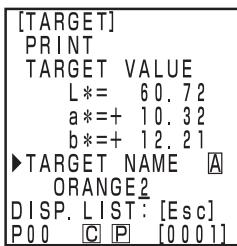
Setting the color difference target color name (example)
(How to set the color difference target color name)
1) Select input mode using the _key
- The input modes change in the following order: upper case Latin letters lower case Latin letters numbers.
2) Move the cursor using the key and input the color difference target color name using the numeric pad.
- The name is up to 9 characters (see P.20 "As input keys" for details.)
7 Once settings are complete, press the Measure/Enter key Measure Enter
- Settings are complete, complete sound beeps and the display returns to the measurement screen.
Settings are now finished. Other color difference target color numbers can be set by repeating the above procedure.
Color difference target colors which have been set can be deleted in the following ways.

Once deleted, they cannot be undone.
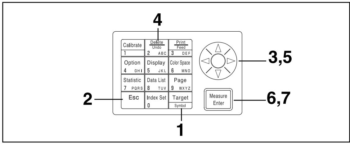
[Operating Procedure]
1 Press the Target Color key while in the measurement screen.
- The color difference target color screen appears.
![KONICA CR-410 - [Operating Procedure] - 1](/content/2025/01/172144/images/0477087413d3a69984e1030491b870019bc996970cf0258370ef2346c1704185.jpg)
Color difference target color screen
Press the Escape key Esc.
- The color difference target color list screen appears.
![KONICA CR-410 - [Operating Procedure] - 2](/content/2025/01/172144/images/97f9cf16118f7b790698e5a36a7a37e5437bc9133bf54494019540ddd516e634.jpg)
List screen
3 Select the color difference target color to deleted using the key.
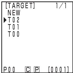
List screen
4 Press the Delete/Undo 2\ Undo\ ABC key.
- The color difference target color deletion screen appears.
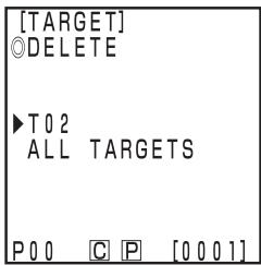
Deletion screen
5 Select either one target color or "ALL TARGETS" using the key.
6 Press the Measure/Enter key Measure Enter
- The color difference target colors deletion message screen will appear.
7 Confirm the message and press the Measure/Enter key. Measure Enter
- Once deletion is complete, complete sound beeps and the display returns to the previous screen.
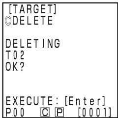
Only deleting the selected target color
(How to change the color difference target color name)
1) Press the Target Color key [Target] while in the measurement screen.
2) Select "TARGET NAME" using the key.
3) Select input mode using the key.
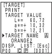
- The input modes change in the following order: upper case Latin letters lower case Latin letters numbers.
4) Move the cursor using the key and input the color difference target color name using the numeric pad. - The name may be up to 9 characters long (See P.20 "As input keys" for details.)
5) When the settings are complete, press the Measure/Enter key Enter - If the color difference target color name has been changed, measurement is not made even if the Measure/Enter key is pressed.
- After the settings are complete, the completion sound is made and the system returns to the measuring screen.
Note
Measurement should be done under the same temperature conditions as calibration and setting of color difference target color.
1) Setting a new color difference target color before every measurement

If the same color difference target color name is used, color difference target color is overwritten.
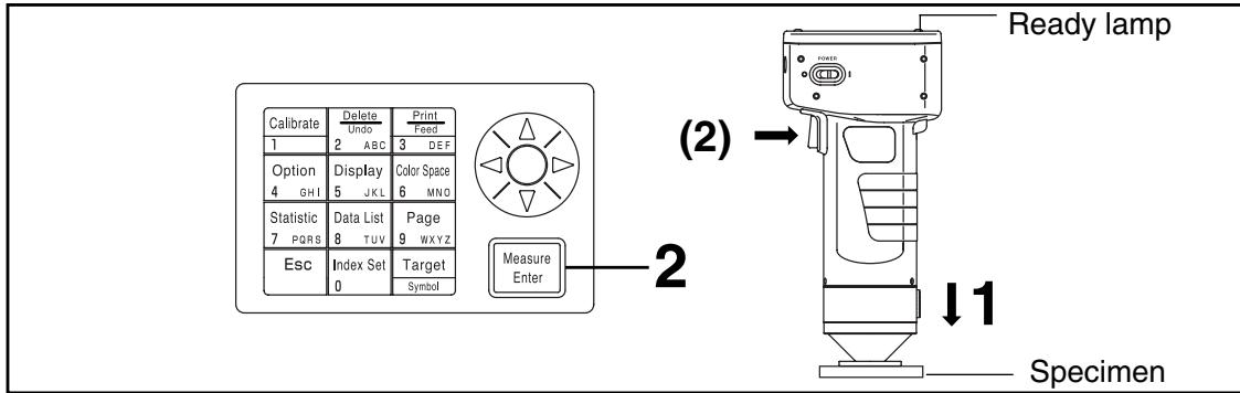
Note
Before Mesurement
- Select the color space and screen for your use.
See P.78 "Selecting the Color Space", and P.81 "Screen Display and Changing the Display" for details.
[Operating Procedure]
1 Place the measuring head vertically above the specimen while in the measurement screen.
![KONICA CR-410 - [Operating Procedure] - 1](/content/2025/01/172144/images/20876648f2fc7f4e6bd74fd04c87947f42e3a473d6d286a820c34bddcf0ee8ec.jpg)
Press the Measure/Enter key (or the measurement button on the measuring head) after making sure the ready lamp is ON.
- Measurement is done and the data is displayed. If the printer is set to ON on the index set screen, the data is printed out.
Note
Do not move the measuring head during measurement.
In case of continuing to set other color difference target color and measure color difference
3 Press the Target Color key Target Symbol
- The color difference target color setting screen appears.
- Press the Print key to print the target value.
Color difference target color name
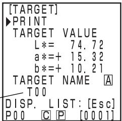
Color difference target color is set to T00.
4 Place the measuring head vertically above the color difference target color specimen.
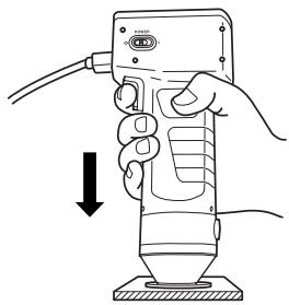
Press the Measure/Enter key (or the measurement button on the measuring head) after making sure the ready lamp is ON.
- Measurement overwrites the color difference target color data to color difference target color name T00.
- Press the Print key to print the target value.
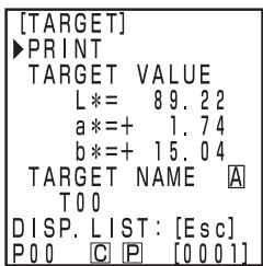
Setting screen
Note
Do not move the measuring head during measurement.
6 Once settings are complete, press the Measure/Enter key ure after
- Settings are complete, complete sound beeps and the display returns to the measurement screen.
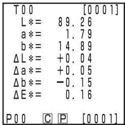
Measurement screen
7 Place the measuring head vertically above the specimen.
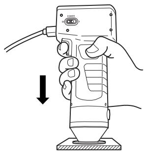
Press the Measure/Enter key (or the measurement button on the measuring head) after making sure the ready lamp is ON.
-
Measurement is done and the data is displayed. If the printer is set to ON on the index set screen, the data is printed.
-
Repeat the above steps 3 through 8.
Note
After Measurement
- Pressing the Color Space key [Color Space] converts the measurement data to other color spaces. (See P.78 "Selecting the Color Space")
- Pressing the Color Space key changes the screen display. (See P.81 "Screen Display and Changing the Display")
INote
- Measured data is automatically stored.
If you do not wish to store data, press the Delete/Undo key 2Base to delete the latest data.
If you mistakenly delete data you wished to keep, press the Delete/Undo key again and the latest deleted data is restored.
Note, however, that if new measurement data replaces the latest deleted data, that data is no longer restorable, since the new data is stored in its place.
- Up to 2000 measurement data sets can be stored.
Oldest data is overwritten if this limit is exceeded.
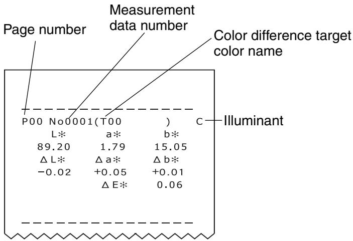
[Printout (example)]
[Screen (example)]
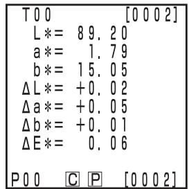
[Setting conditions] Select L^a^b^* color space and absolute/ color difference display
- Press the Print/Paper Feed key 3Cost anytime you want to print out the data displayed in the LCD.
2) Selecting a pre-existing color difference target color before measurement
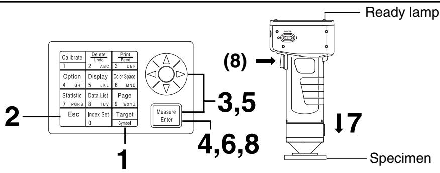
Note
Before Mesurement
- Select the color space and screen for your use.
See P.78 "Selecting the Color Space", and P.81 "Screen Display and Changing the Display" for details.
Operating Procedure
1 Press the Target Color key while in the measurement screen.
- The color difference target color setting screen appears.
- The currently selected target color is displayed.
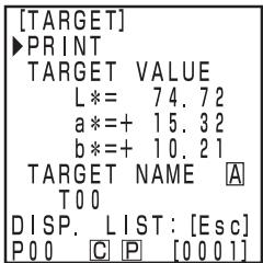
Color difference target color is set to T00.
Press the Escape key Esc.
- The color difference target color list screen appears.
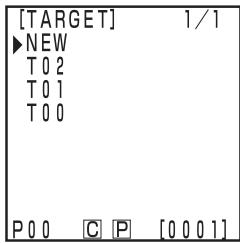
3 Select the color difference target color for measurement using the key.
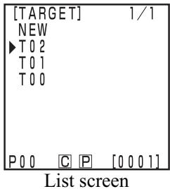
4 Press the Measure/Enter key Measure Enter
- The target color Edit/Change selection screen appears.
5 Select "CHANGE" using the key.
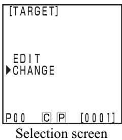
6 Press the Measure/Enter key Measure Enter
- Settings are complete, complete sound beeps and the display returns to the measurement screen.
- The currently selected target color is displayed.
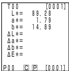
Measurement screen (previous measurement data)
7 Place the measuring head vertically above the specimen.
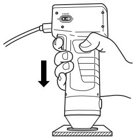
Press the Measure/Enter key (or measurement button on the measuring head) after making sure the ready lamp is ON.
- Measurement is done and the data is displayed. If the printer is set to ON on the index set screen, the data is printed out.
Note
Do not move the measuring head during measurement.
Note
After Mesurement
- Pressing the Color Space key [Color Space] converts the measurement data to other color spaces. (See P.78 "Selecting the Color Space")
- Pressing the Color Space key Space SWC changes the screen display. (See P.81 "Screen Display and Changing the Display")
Note
- Measured data is automatically stored.
If you do not wish to store data, press the Delete/Undo key 2_c to delete the latest data.
If you mistakenly delete data you wished to keep, press the Delete/Undo key again and the latest deleted data is restored.
Note, however, that if new measurement data replaces the latest deleted data, that data is no longer restorable, since the new data is stored in its place.
-
Up to 2000 measurement data sets can be stored.
-
When data protection is set to OFF and data quantity exceeds 2000 items, the oldest page that contains measurement data will be deleted, and a data storing area will be secured. (If the page to be deleted is page 0, the relevant page remains, but the measurement data on this page will be deleted.) If there is no page that contains measurement data other than the current page, the oldest data on the current page will be overwritten.
-
When data protection is set to ON, a measurement error occurs, and the "Data Memory Full" error message appears.
Functions
Updating the Page
This instrument allows users to store measurement data (up to 2000 sets) into 100 pages (page 00 to 99).
For example, 20 specimens are measured and the measurement data is stored in page 00.
Next, the page is updated to page 01, and 50 sets of specimen measurement data are stored there. In this way, up to 2000 sets of data can be added in each pages.
- Statistical operations and printing of all data using the Data List key are performed by page.
The default is page 00.
- If data protection is OFF, old pages are deleted and replaced with any new pages after page 99.
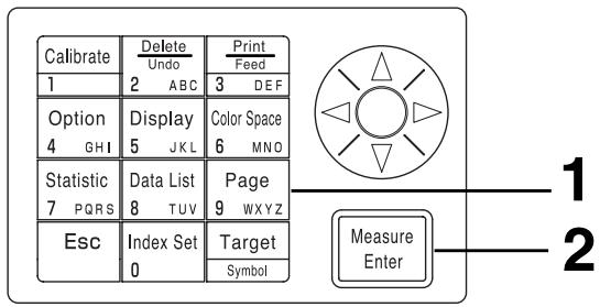
[Operating Procedure]
Press the Page key 9 wxyz while in the measurement screen.
- The page list screen appears.
![KONICA CR-410 - [Operating Procedure] - 1](/content/2025/01/172144/images/02fa8c474af0491591a3fa5eb1aa19a189b07fd0afc05c1ae4fbb2a2f2bb1979.jpg)
List screen
2 Press the Measure/Enter key with the cursor at new position.
- After updating to the new page, the beep sounds and the display returns to the measurement screen.
![KONICA CR-410 - [Operating Procedure] - 2](/content/2025/01/172144/images/7de4cfbf098ca4703e765113747feaa6d0e1aa793ad995494b6b530d4d4e0faf.jpg)
New page Measurement screen
![KONICA CR-410 - [Operating Procedure] - 3](/content/2025/01/172144/images/3924a46859e2d15846457cec1c51c12295642c9100ec1f65de41fb31b4e0de25.jpg)
[Operating Procedure]
1 Press the Page key \\wxyz while in the measurement screen.
- The page list screen appears.
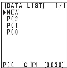
List screen
2 Select a page using the key.
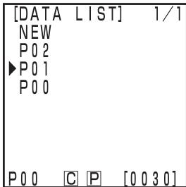
3 Press the Measure/Enter key Measure Enter
- The measurement screen for the selected page appears
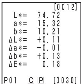
Measurement screen
<1 Displaying Individual Data Sets>
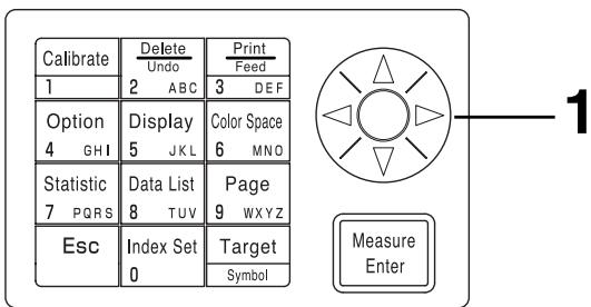
[Operating Procedure]
Press the key while in the measurement screen.
- The data set changes every time the key is pressed.
- Only data in the currently selected page can be displayed.
- Pressing the Escape key Esc returns to the latest data display.
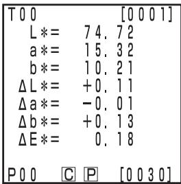
Measurement screen
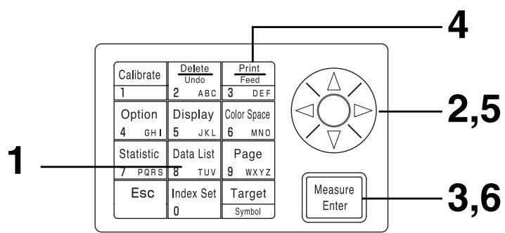
[Operating Procedure]
1 Press the Data List key Data List while in the measurement screen.
- The data list screen appears.
![KONICA CR-410 - [Operating Procedure] - 1](/content/2025/01/172144/images/b170680e94eb1463f17028d4f349796566e32828ad2a7a6491eb039743ce9761.jpg)
List screen
2 Select a page using the key.
![KONICA CR-410 - [Operating Procedure] - 2](/content/2025/01/172144/images/3f278feb817e179fc743e893d1126076b1f0ea86fb9a2e0c4719c26ab85e6699.jpg)
Press the Measure/Enter key Measure Enter
- The measurement data screen of the selected page is displayed. It is not possible to add (measure) new data here.
![KONICA CR-410 - [Operating Procedure] - 3](/content/2025/01/172144/images/7ae71923670d8456413b8adac1294eba375a536ea411d7d5646c51a7b58201f8.jpg)
Measurement data screen
In case of printing all data
Press the Print/Paper Feed key
- The selectin screen appears.
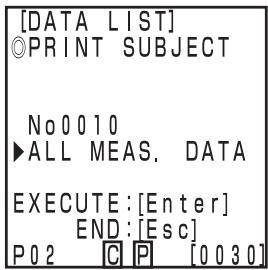
5 Select "ALL MEAS. DATA" using the key.
6 Press the Measure/Enter key Measure Enter
- All data in the selected page are printed from the latest data in oder. After printing, the display returns to the data list screen.
- Pressing the Escape key Esc twice returns to the measurement screen.
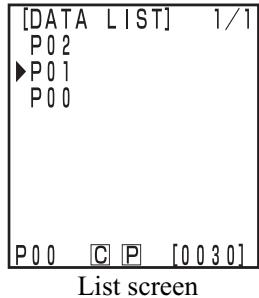
This instrument can perform statistical operations (maximum, minimum, agerage, standard deviation) on stored data. These operations are performed on all the chroma or color difference data stored in one page.
1
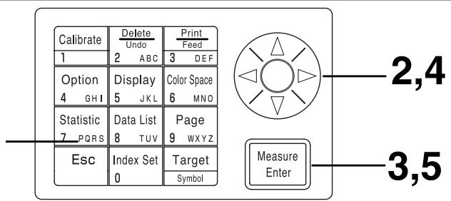
[Operating Procedure]
Change to the color space for the statistical operations.
Press the Statistical Operation key Statistic while in the measurement screen.
- The statistical operation screen appears.
2 Select a page using the key.
Press the Measure/Enter key Measure Enter
- The absolute value/color difference screen appears for the statistical operation.
4 Select "ABS. VALUE" or "DIFF. VALUE" using the key .
5 Press the Measure/Enter key Measure Enter
- The results of the statistical operation are displayed after the operating screen.
[MAX]... maximum [MIN] ... minimum
[AVG] ... average [SD] ... standard deviation
- Pressing the Escape key Esc returns to the previous screen.
![KONICA CR-410 - [Operating Procedure] - 1](/content/2025/01/172144/images/661602426f0edb1c131c2b45fe23b5cf756f68f97b364a23aea00b97689db77d.jpg)
Statistical operation screen
![KONICA CR-410 - [Operating Procedure] - 2](/content/2025/01/172144/images/c753e52fa6d38a9d7223a8395ea5cce30117b0729753340acb7b082655859a1e.jpg)
Statistical operation screen
![KONICA CR-410 - [Operating Procedure] - 3](/content/2025/01/172144/images/ee33da2a7e295a32eb5020c7ea94c2f09fa60792508f6d99a3b5f95cd9b79558.jpg)
Absolute value/color difference screen
![KONICA CR-410 - [Operating Procedure] - 4](/content/2025/01/172144/images/d6a4ec02b2340418e494857893e132b426a018b2c5ed725d6e61b92de906aa62.jpg)
Statistical operation results screen
![KONICA CR-410 - [Operating Procedure] - 5](/content/2025/01/172144/images/5d81206aa670c3c6b935e9a0a7c882bd318d241fbc6fe8b55b649a591277267f.jpg)
![KONICA CR-410 - [Operating Procedure] - 6](/content/2025/01/172144/images/d00f52790037e00928472636c35aebae942cf760f43e666501e74f1a526e3f46.jpg)
[Setting conditions] Select L*a*b color space and absolute display
First date & time of P00 measurement
Last date & time of P00 measurement
![KONICA CR-410 - [Operating Procedure] - 7](/content/2025/01/172144/images/579d55c083900b5c5d3f98efd403cba4dc9c797a6bd0db6696cff1f1f58d54a1.jpg)
![KONICA CR-410 - [Operating Procedure] - 8](/content/2025/01/172144/images/4f4f10a23b1cefaf9633936db2666859ac516f6cc2adfc6a6635717412ea3cdf.jpg)
[Setting conditions] Select L*a*b color space and color difference display
There are four ways of deleting data: only the latest data, only the selected 1 data, by page, and all data. The operating procedure is described below.
1
| Calibrate | Delete Undo | Print Feed | ||
| 1 | 2 | ABC | 3 | DEF |
| Option | Display | Color Space | ||
| 4 GHI | 5 | JKL | 6 | MND |
| Statistic | Data List | Page | ||
| 7 PQRS | 8 | TUV | 9 | WXYZ |
| Esc | Index Set | Target | ||
| 0 | Symbol | |||
![KONICA CR-410 - [Operating Procedure] - 1](/content/2025/01/172144/images/bba0b45369e527ef930d3476a16a67af8f9f601a017fe63e5245bc2fcbde1b69.jpg)
Measure Enter
[Operating Procedure]
1 Press the Delete/Undo key \ \ 2 while in the measurement screen.
- Only the latest data is deleted and the display returns to the previous measurement screen.
- Pressing the Delete/Undo key once more restores the latest data.
Note, however, that if new measurement data replaces the most recently deleted data, that data will no longer be restorable, since the new data will be stored in its place. If you change the page after deleting the latest data, the deleted data cannot be restored.
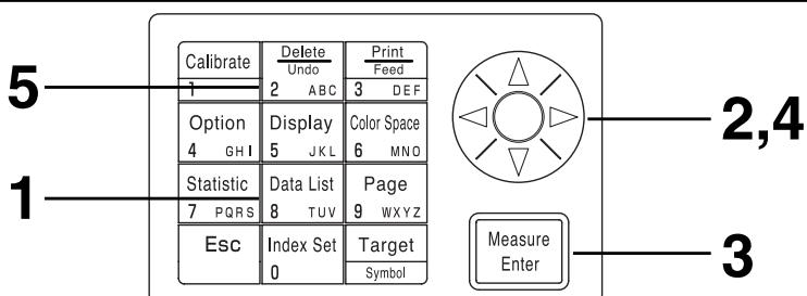
[Operating Procedure]
Press the Data List key while in the measurement screen.
- The data list screen appears.
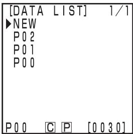
List screen
2 Select a page using key.
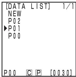
3 Press the Measure/Enter key Measure Enter
- The measurement data screen of the selected page is displayed. It is not possible to add (measure) new data here.
4 Select the measurement data using the key.
- The deletion screen will appear.
5 Press the Delete/Undo Delete \ Undo \ 2 key.
- The selected data is deleted and the deletion screen appears.
- Pressing the Delete/Undo key 2 once more undoes the latest data.
- Statistics operation does not calculate deleted data.
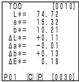
Measurement data screen
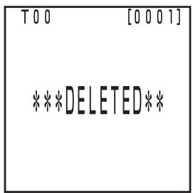
Deletion screen
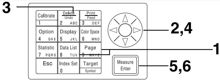
Once deleted, data cannot be undone.
[Operating Procedure]
1 Press the Page key or the Data List key while in the measurement screen.
- The page screen or the data list screen appears.
2 Select a page to delete using the key. In case of deleting all page
Select any page using key.
- Any page can be selected.
3 Press the Delete/Undo key 2 Undo 2 ABC
- The page or the data list deletion selection screen appears.
4 Select the selected page only or "ALL PAGES" using the key.
5 Press the Measure/Enter key Measure Enter
- The page deletion message screen will appear.
6 Press the Measure/Enter key Measure after confirm the message on the screen.
- Once deleting is complete, complete sound beeps and return to the previous screen.
![KONICA CR-410 - [Operating Procedure] - 1](/content/2025/01/172144/images/1d4a429953a85df691409e5a20e9017b52698d064abbfe994fa2ec39d2091654.jpg)
![KONICA CR-410 - [Operating Procedure] - 2](/content/2025/01/172144/images/d708550883c2ac630f6d34ad21d94eb846971ccfec7588197577a2a429c003e0.jpg)
![KONICA CR-410 - [Operating Procedure] - 3](/content/2025/01/172144/images/b80538d92dba54bc0b2c0f144fcd131c5a17c6da6c752c7c02420edc4bfcf86c.jpg)
![KONICA CR-410 - [Operating Procedure] - 4](/content/2025/01/172144/images/64783d5f9db0eca42f6a7303b6462dd1e4d08154bd39b506d646d40a3d308102.jpg)
The optional setting include the following five settings.
1) Tolerance Setting the color difference tolerance.
2) Auto. measurement Setting the interval time and end time for automatic measurement.
3) Date & time Setting the internal clock.
4) Import Transfers data from the measuring head to the data processor.
5) Multi-calibration Setting the multi-calibration function.
![KONICA CR-410 - [Operating Procedure] - 5](/content/2025/01/172144/images/9aacd933faad071eb1a4dd1ad914fb79080c38c6e9a01234a5302030a727ea9d.jpg)
[Operating Procedure]
1 Press the Option key 4 0+1 while in the measurement screen.
- The option screen appears.
[OPTION]
TOLERANCE
AUTO MEAS.
DATE & TIME
IMPORT
MALTICAL.
P00 [P] [0001]
Option screen
2 Select the item using the key.
[OPTION]
TOLERANCE
AUTO MEAS
DATE & TIME
IMPORT
MALTICAL.
P00 C P [0001]
Press the Measure/Enter key Measure Enter
- The setting screens for each item appears.
See the following operating procedures for setting each item.
Items
1) Tolerance .. see P.116 - 124
2) Auto. measurement ... see P.125
3) Date & time. see P.71
4) Import.. see P.126
5) Multi-calibration .. see P.127
This instrument can make judgments based on a color difference tolerance for the measurement value of the color difference target color.
When measuring color difference, if the measured value is within the color difference tolerance set for the color difference target color, "PASS" is displayed, if it is at the warning level "WARN", and if it is out of the range "FAIL" is displayed is displayed. It is possible to judge whether the data is close to the tolerance by setting an appropriate warning level (i.e. what percent of the tolerance). If the buzzer is set to ON, an error beep sounds when the judgment is "FAIL".
The four methods for setting the color difference tolerance for judgment are shown below.
1) Elliptical tolerance: allows setting a tolerance on the basis of an ellipse. This makes it possible to display the color difference in results closer to what is visible to the naked eye.
2) Box tolerance: allows setting a tolerance independently for each component like “L”, “a”, “b*”, etc. This type is easy to understand and makes calculation easy, too.
3) E : allows setting a tolerance based on the color difference ( E ) with the target color.
4) Box tolerance and E : allows setting a tolerance combining (2) and (3) above.
"O" is displayed if no tolerance is set.
It is possible to set various color difference tolerance for one set of color difference target color data. However, the following restrictions apply to the type of color difference tolerance which can be set depending on the color space.
See P.80 "Color Space and Color Difference Setting" for details.
- None of the color difference tolerance above (1 - 4) can be set for "Munsell" or "User Index."
- Only 2 above can be set for "CIE WI/Tw", "WI E313", "YI D1925", and "YI E313".
E in 3) and 4) above is displayed as follows depending on the set color space.
E^* , E, E94, E99, E00 ,CMC
Even if the color space is changed after the color difference tolerance is set, it is managed using the color space present when the tolerance was set. Therefore, judgment is made on the measurement values calculated internally on the basis of the color space at the time the tolerance was set, and not the color space selected in the measurement screen. Further, the color space systems at time of setting are used for redisplaying the existing tolerance and input rules when changing settings.
It is not possible to input a tolerance for only one component. (for Ex. L* only) In this case, set a large tolerance for the other components.
Although it is possible to change the type or value of the tolerance after the color difference tolerance is set, it is impossible to cancel it. To cancel the color difference tolerance, it is necessary to either select a color difference target color for which a tolerance has not been set or delete the color difference target color for which the tolerance has been set.
The following description uses the "Lab" color space for example.
The input ranges for the set values are as follows.
(Tolerance) Y: 0.01 to 99.99, xy: 0.0001 to 0.9999, other than Yxy: 0.05 to 80.00
(Offset) -5.00 to +5.00 (should be within tolerance)
(Rotation) -45 to +45
(Warning level) 10 to 100%
Note
Do not enter "space" for color difference tolerance. If you enter "space", it will be processed as a numeric value "0". For example, if you enter 5..00 (".." means "space") by mistake, though you intended to enter 5.00, the setting value will be 50.00 against your intention.
Elliptical tolerance
This judges whether or not the value of the measured color difference is within the range of the elliptical tolerance set for the color difference target color. When setting an elliptical tolerance, besides the tolerance value, an offset and a rotation can also be set.
If the set color space is "LCh" the col or difference tolerance is set along the "Lab*" color space axis, and if the set color space is "L99C99h99" then the "L99a99b99" color space axis is used.
See P.80 "Color Space and Color Difference Setting" for details.
Set a color difference target color ahead of time before setting an elliptical limit.
Since the color difference graphs are displayed in two dimensions, the fail judgment data may sometimes be displayed as plotted inside the tolerance in each graph.
5,7
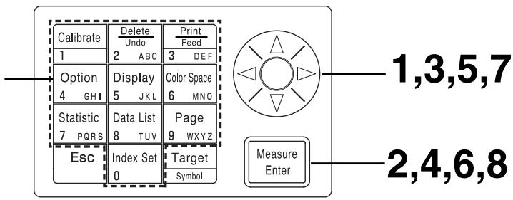
Selecting the limit value in P.115 displays the [limit value] selection screen.
[Operating Procedure]
1 Use the key to select a color difference target color.
![KONICA CR-410 - [Operating Procedure] - 1](/content/2025/01/172144/images/b4be611890b89fbc43b8bf2ae4d46d9bc04842f2cedc72da2e55e0070554e4c1.jpg)
Press the Measure/Enter key Measure Enter
- The tolerance type screen appears.
![KONICA CR-410 - [Operating Procedure] - 2](/content/2025/01/172144/images/1c95bf62c47ec8a7f84e661ed675d08105ad805ee3f660992e6eed7001048cfd.jpg)
3 Select the "ELLIPTICAL" as tolerance type.
4 Press the Measure/Enter key Measure Enter
- The limit value/offset setting screen appears.
- If a color difference tolerance is already set, go to step 6 as the set color difference tolerance data is displayed.
![KONICA CR-410 - [Operating Procedure] - 3](/content/2025/01/172144/images/bc19c7d827f20bc8c91008fa04384be8846c7a59bd68f4ab27c4e15bece83ea8.jpg)
Setting screen
5 Set the color difference tolerance and the offset using the key and the numeric pad.
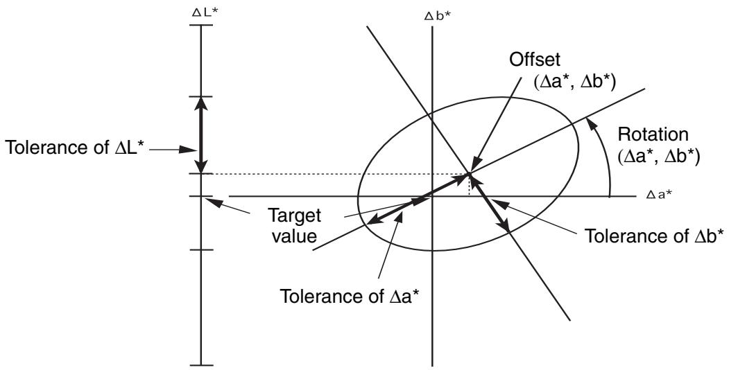
Input ranges for the set values
(Tolerance) Y: 0.01 to 99.99, xy: 0.0001 to 0.9999, other than Yxy: 0.05 to 80.00
(Offset) -5.00 to +5.00 (should be within to tolerance)
(Rotation) -45 to +45
(Warning level) 10 to 100%
If the rotation is set, the graph showing tolerance range is not made.
6 Press the Measure/Enter key Measure Enter
- The gradient/warning level setting screen is displayed.
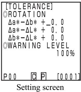
7 Set the rotation and the warning level using the key and the numeric pad.
Press the Measure/Enter key Measure Enter
- Once the elliptical tolerance setting is complete, the measurement screen appears.
- Measurement points within the color difference tolerance are plotted as O, warning level points are plotted as , and points out of the color difference tolerance are plotted as X.
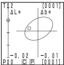
Measurement result (example)
Box tolerance
This judges whether or not the value of the measured color difference is within the range of the box tolerance limit set for the color difference target color. When setting a box-type tolerance, color difference tolerance (±) for each color difference target color can also be set.
Set a color difference target color ahead of time before setting a box tolerance.
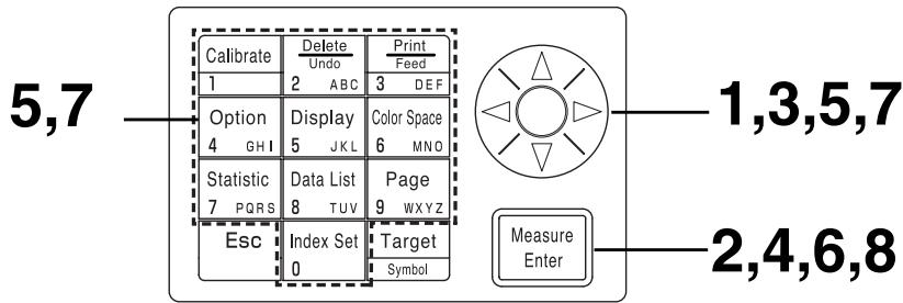
Selecting the limit value in P.115 displays the [limit value] selection screen.
[Operating Procedure]
1 Use the key to select a color difference target color.
![KONICA CR-410 - [Operating Procedure] - 1](/content/2025/01/172144/images/2430441545dd9c06af58d0ea3970343ef12df9e54b759bb86d6787354b5ea58a.jpg)
Selection screen
2 Press the Measure/Enter key Measure Enter
- The tolerance type screen appears.
3 Select the "BOX" as the tolerance type.
![KONICA CR-410 - [Operating Procedure] - 2](/content/2025/01/172144/images/e1726e8c8802c1f70462a623b013868327ebc14dee5abb7599b775564705d3bb.jpg)
Tolerance type screen
4 Press the Measure/Enter key Measure Enter
- The limit value setting screen will appear.
- If a color difference tolerance is already set, go to step 6 as the set color difference tolerance data is displayed.
![KONICA CR-410 - [Operating Procedure] - 3](/content/2025/01/172144/images/184e3f36c183053654058f4af3261fbf131a6404e74a8bb2839f8de1a5683373.jpg)
Setting screen
Set the color difference tolerance using the key and the numeric pad.
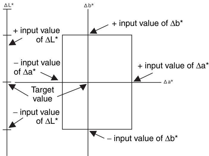
5
Input ranges for the set values
(Tolerance) Y: 0.01 to 99.99, xy: 0.0001 to 0.9999, other than Yxy: 0.05 to 80.00
(Offset) -5.00 to +5.00
Rotation) -45 to +45
(Warning level) 10 to 100%
6
Press the Measure/Enter key Measure Enter
- The warning level setting screen appears.
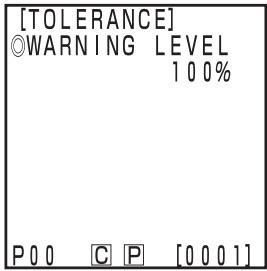
8
Setting screen
7
Set the warning level using the key and the numeric pad.
Press the Measure/Enter key Measure Enter
- Once the box tolerance setting is complete, the measurement screen appears.
- Measurement points within the color difference tolerance are plotted as O, warning level points are plotted as , and points outs of the color difference tolerance are plotted as X.
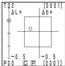
Measurement result
E
This judges whether or not the value of the measured color difference is within the range of the E set for the color difference target color.
E is displayed as followings depending on set color spaces.
E^* , E, E94, E99, E00 ,CMC
Set a color difference target color ahead of time before setting E .
5,7
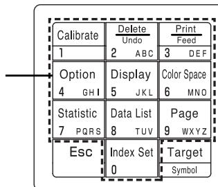
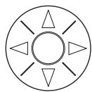
Measure Enter
1,3,5,7
2,4,6,8
Selecting the limit value in P.114 displays the [limit value] selection screen.
[Operating Procedure]
1
Use the key to select a color difference target color.
![KONICA CR-410 - [Operating Procedure] - 1](/content/2025/01/172144/images/2cff73673e04565b6d711fbbb7204c6938cc8bdfedf1132f3fdda7a478d61bce.jpg)
Selection screen
2
Press the Measure/Enter key Measure Enter
- The tolerance type screen appears.
3
Select the “ E^* ” as the tolerance type.
![KONICA CR-410 - [Operating Procedure] - 2](/content/2025/01/172144/images/20c65a3529f5f670a431105798a9a06db32dc84ccc2d7bf27942bf4d5ce07fcc.jpg)
Tolerance type screen
4
Press the Measure/Enter key Measure Enter
- The limit value setting screen will appear.
- If E is already set, go to step 6 as the set color difference tolerance data is displayed.
![KONICA CR-410 - [Operating Procedure] - 3](/content/2025/01/172144/images/f8b5712cd984c0e23bacdefa04b20e72d08203d5ef8663954e462a860e637517.jpg)
Setting screen
5 Set the E using the key and the numeric pad.
Input ranges for the set values
(Tolerance) Y: 0.01 to 99.99, xy: 0.0001 to 0.9999, other than Yxy: 0.05 to 80.00
(Offset) -5.00 to +5.00 (should be within to tolerance)
(Rotation) -45 to +45
(Warning level) 10 to 100%
6 Press the Measure/Enter key Measure Enter
- The warning level setting screen appears.
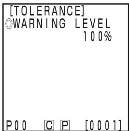
Setting screen
7 Set the warning level using the key and the numeric pad.
Press the Measure/Enter key Measure Enter
- Once E setting is complete, the measurement screen appears.
- Measurement points within the color difference tolerance are plotted as O, warning level points are plotted as , and points out of the color difference tolerance are plotted as X.
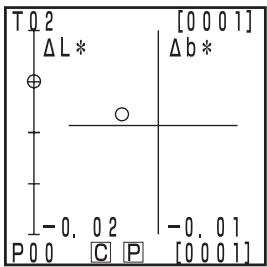
Measurement result
Box tolerance and E
This judges both box tolerance and E .
5,7
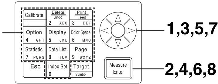
Selecting the limit value in P.115 displays the [limit value] selection screen.
[Operating Procedure]
1
Use the key to select a color difference target color.
![KONICA CR-410 - [Operating Procedure] - 1](/content/2025/01/172144/images/ccb72959a2fbc45631e8e4e4999503623c5870dcd4d4c27cb3d0f2b707d91fdc.jpg)
Selection screen
Press the Measure/Enter key Measure Enter
- The tolerance type screen appears.
3 Select the "BOX & E^* " as the tolerance type.
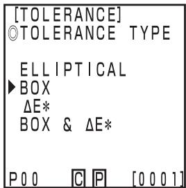
Tolerance type screen
4 Press the Measure/Enter key Measure Enter
- The limit value setting screen will appear.
- If color difference tolerance and E are already set, go to step 6 as the set color difference tolerance data is displayed.
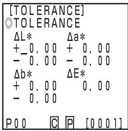
Setting screen
5
Set the color difference tolerance and E using the key and the numeric pad.
Input ranges for the set values
(Tolerance) Y: 0.01 to 99.99, xy: 0.0001 to 0.9999, other than Yxy: 0.05 to 80.00
(Warning level) 10 to 100%
6
Press the Measure/Enter key Measure Enter
- The warning level setting screen appears.
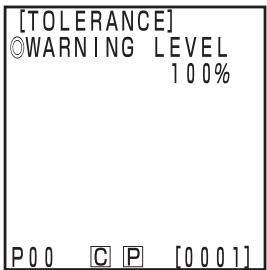
Setting screen
7
Set the warning level using the key and the numeric pad.
8
Press the Measure/Enter key Measure Enter
- Once box color difference tolerance and E setting are complete, the measurement screen appears.
- Measurement points within the color difference tolerance are plotted as O, warning level points are plotted as , and points out of the color difference tolerance are plotted as X.
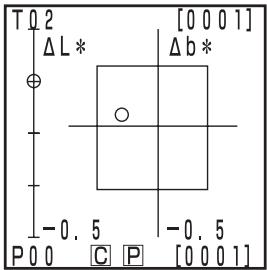
Measurement result
Note
No key other than the Escape key Esc functions after the timer is set and the instrument goes into automatic measurement standby status. Be sure to set color space, display, color difference target color, and other settings ahead of time.
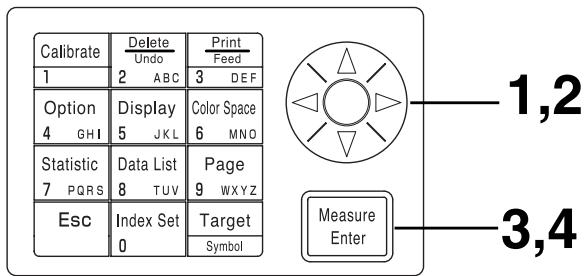
Selecting timer in P.115 displays the [timer] setting screen.
1 Move the cursor using the key and set the interval time using the numeric pad.
(Input range) 00m03s to 99m59s
- Set interval time longer than a measurement time which includes the number of measurements for average and printing.
Press the Measure/Enter key Measure Enter
- The end time setting screen appears.
3 Move the cursor using the key and set the end time using the numeric pad.
- Enter a time which exists in the calendar until 2099. The display uses 24-hour time.
- If no end time is entered, measurement is endless.
4 Press the Measure/Enter key Measure Enter
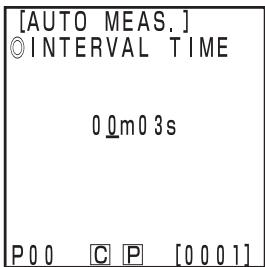
Setting screen
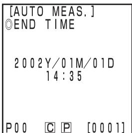
Setting screen
- Once settings are complete, the display returns to the measurement screen.
Press the Measurement key Measure Enter to start measurement.
- Press the Escape key [Esc] (for a long time) to cancel automatic measurement.
- All other keys does not work.
- The buzzer sounds approximately every second during automatic measurement. (Only if the buzzer setting is ON.)
- If battery power is used, the measurement time becomes longer as the battery voltage drops, so we recommend using the AC adapter.
- The timer measurement icon [L] is displayed.
It is possible to transfer data stored in the measuring head to the data processor.

Import actually moves the data, and does not simply copy it.
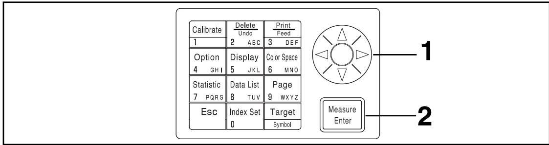
Selecting multi-calibration in P.115 displays the [multi-calibration] selection screen.
1 Move the cursor using the key and select the page to import.
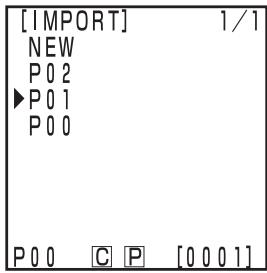
Selection screen
Press the Measure/Enter key Measure Enter
- After the processing screen, import is complete, and the display returns to the measurement screen.
- If the selected page contains data, newer data is registered after the existing data.
- Import will not be performed if there are more than 2000 sets of data.
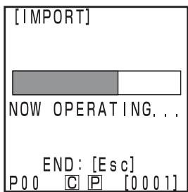
Processing screen

If you press the Escape key when data transfer is executed, the data transfer operation stops. In this case, data transfer until the stop point has been completed. Since data transfer is executed in sequence from the oldest data, the measurement screen on the measuring head display is apparently unchanged (the latest measurement data are displayed on the screen), but the measuring head retains data that have not been transferred.
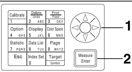
Selecting multi-calibration in P.115 displays the [multi-calibration] selection screen.
1 Move the cursor using the key and select "ALL CHANNELS".
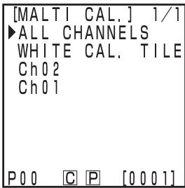
Selection screen
Press the Measure/Enter key Measure Enter
- Once multi-calibration setting is complete, the display returns to the measurement screen.
- See P.135 "Setting the Multi-calibration" for details on multicalibration.
User Index
- It is possible to resist an operational expression based on the color space to the measuring head. Simply displaying the user's own index as measurement results eliminates the need to do calculations based on the measurement values, making more convenient color management on the job.
- A PC is used to write the operational expression to the measuring head, and up to six can be registered. This can be done automatically by connecting a data processor to the measuring head.
- The optional CR-400 utility software CR-S4w or Color data software ChromaMagic CR-S3w is needed to write the user index.
See the operation manual for the CR-400 utility software CR-S4w or Color data software ChromaMagic CR-S3w for details on how to write the user index.
Data can be transferred between the instrument and a PC by connecting the instrument's RS-232C terminal to a PC.
When using the instrument continuously for long periods of time or when performing data transfer using the RS-232C terminal, we recommend using the AC adapter (AC-A17) when connected to a PC because of the higher power consumption involved.
By connecting the instrument to a PC/AT compatible PC using the optional RS-232C cable CR-A102, the data stored in the instrument memory can be sent to a PC.
Use the optional CR-400 utility software CR-S4w or the Color data software ChromaMagic CR-S3w when connecting the instrument to a PC.
The followings can be used in remote mode:
- Outputting measurement and target color data to a PC
- Deleting measurement data
See P.129 "Changing to Remote Mode" for details.
Notes on Use
- When connecting, make sure that the connectors are correctly oriented and fastened securely with screws.
- Before connecting, make sure that the power to both the instrument and PC is turned OFF.
- Hold the connector when connecting or disconnecting. Do not bend, pull, or apply undue pressure to the cord, as this may cause it to break.
- Do not touch the connector terminals with your hand. Doing so may cause them to get dirty or subject them to excessive force.
- Make sure that the cable is long enough. Tensioning the cable may cause connection failure or wire breakage.
-
If optional RS-232C cable CR-A102 is not used, make sure the cable specifications match the pin number/signal connection diagram for an RS-232C cable below. An inappropriate cable will prevent data from being input and output properly and may cause malfunctions.
-
Communication Parameters
| Item | Setting |
| Baud rate | 19200bps |
| Character length | 8bit |
| Parity | None |
| Stop bit | 1bit |
- RS-232C connection cable pin number/signal connection diagram
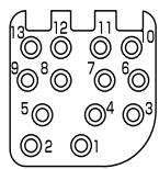
Instrument
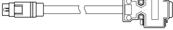
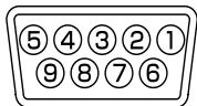
PC
(for D-sub 9 pins)
| Pin No. | Signal | Signal | Pin No. | |
| 6 | RXD | RXD | 2 | |
| 7 | TXD | TXD | 3 | |
| 8 | RTS | GND | 5 | |
| 9 | CTS | RTS | 7 | |
| 10 | GND | CTS | 8 |
- Accessories equipment connected the analog and digital interfaces must be certified to the respective IEC standards (i.e. IEC950 for data processing equipment.)
- Furthermore all configurations shall comply with the system standard IEC 1010-1, Everybody who connects additional equipment to the signal input part or signal output part configures a electoral equipment for measurement system, and is therefore, responsible that the system complies with the requirements of the system standard (IEC 1010-1. If in doubt, consult the technical services department or your local representative.)
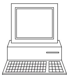
PC
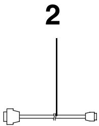
RS-232C cable
CR-A 102
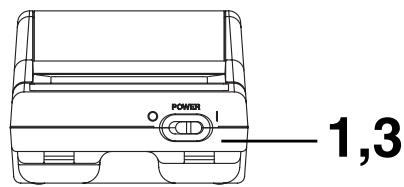
[Operating Procedure]
1 Turn the power OFF (O).
2 Connect the instrument to the PC using the RS-232C cable.
RS-232C terminal
![KONICA CR-410 - [Operating Procedure] - 1](/content/2025/01/172144/images/0f970558532d66e9c65a838348b8cf5ae74fae703f8dded80213227cbf022afa.jpg)
3 Turn the power ON (I).
Power switch
![KONICA CR-410 - [Operating Procedure] - 2](/content/2025/01/172144/images/155eb4c4563565d26e5e4312abda1f47f354a888612d487e4471740deb606c4f.jpg)
![KONICA CR-410 - [Operating Procedure] - 3](/content/2025/01/172144/images/79c7d3e457bb612bd02d7b2cd5554cdacd8ab8f94d48e4f24dc1ae6bd4680c24.jpg)
4 Press the Index Set key Index Set while in the measurement screen.
- The index set screen appears.
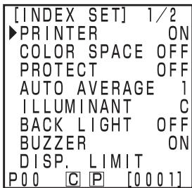
Index set screen (1/2)
5 Press the _^ key to change to page 2/2.
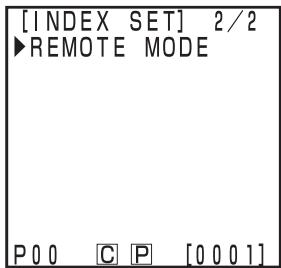
Index set screen (2/2)
6 Press the Measure/Enter key Measure Enter
- The remote mode screen appears.
- Pressing the Escape key Esc returns to the measurement screen.
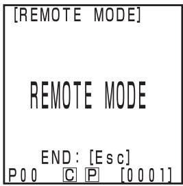
Remote mode screen
Note
When removing the RS-232C cable, turn OFF the measuring head and data processor and push the lock release button certainly while removing the cable.
If the lock is not released and remove it by force, the connector may be damaged.
Lock release button
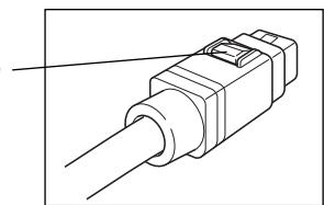
User Calibration Procedure Flow
The relationship between selected calibration and multi/manual select calibration is shown in the flowchart below.
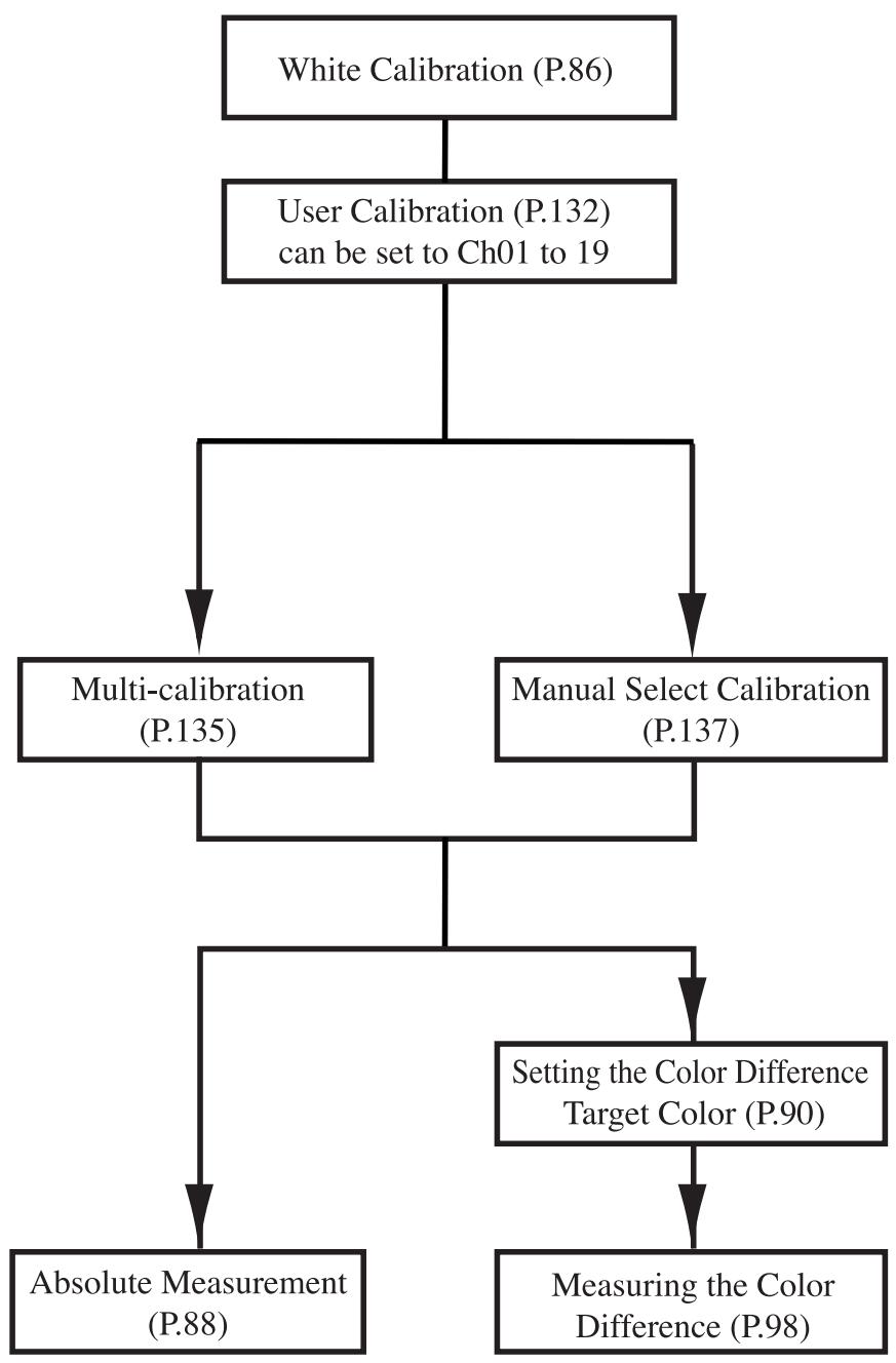
This function allows the user sets the "valued" reference specimen already in possession as the user calibration data to be used to correct indicated values during measurement.
There are two ways of doing this: multi-calibration and manual select calibration
See P.135 "Setting the Multi-calibration" and P.137 "Setting the Manual Select Calibration" for details on setting multi-calibration and manual select calibration.
There are two color spaces which can be used as user calibration data: Yxy, Lab*.
Note
Calibration should be done under the same temperature conditions as measurement.
- User calibration cannot be done if white calibration is not done ahead of time.
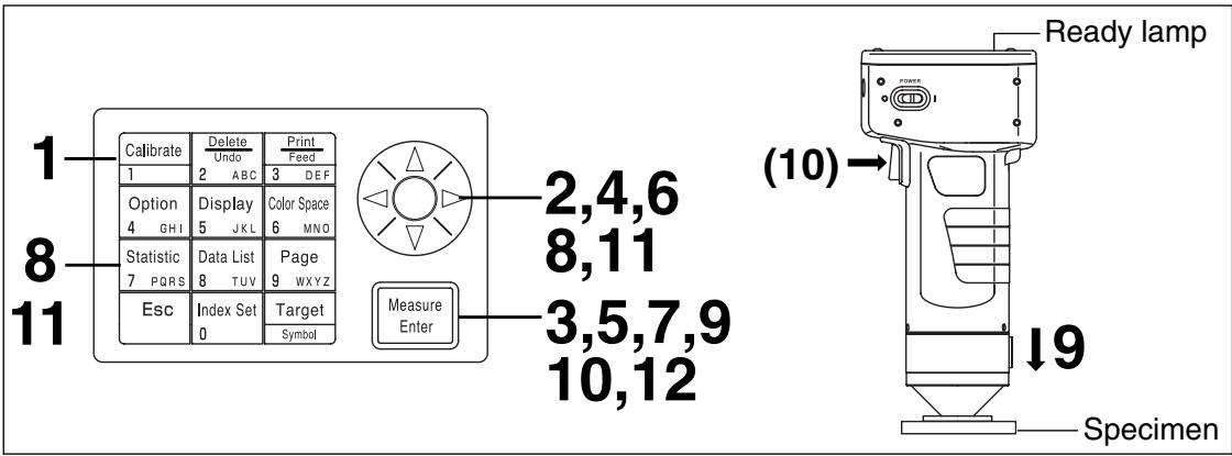
[Operating Procedure]
1 Press the Calibration key Calibrate while in the measurement screen.
- The calibration screen appears.
![KONICA CR-410 - [Operating Procedure] - 1](/content/2025/01/172144/images/2df3304f333196d89c46a2952c2e691d850dcf1178257875a7742822a3319956.jpg)
Calibration screen
2 Select "USER CALIB." using the key.
![KONICA CR-410 - [Operating Procedure] - 2](/content/2025/01/172144/images/55695230c9e88ac92269c315d58cbda882585286639fafcc594f9c2af3fd6c32.jpg)
Press the Measure/Enter key Measure Enter
- The user calibration list screen appears.

List screen
4 Select "NEW" using the key.
- To overwrite data onto an existing calibration channel, select that channel.
Chalibration channel
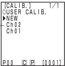
5 Press the Measure/Enter key Measure Enter
- The calibration color space setting screen will appear.
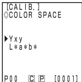
Selection screen
6 Select a color space using the key.
7 Press the Measure/Enter key Measure Enter
- The user calibration setting screen appears.
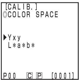
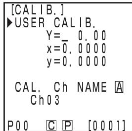
Setting screen
8 Move the cursor using the key and set the value using the numeric pad.
Input range: 0.01 ≤ X, Y, Z ≤ 160
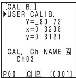
Setting screen
9 Place the measuring head vertically above a target specimen.
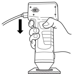
10 Press the Measure/Enter key (or measurement button on the measuring head) after making sure the ready lamp is ON.
Note
- Do not move the measuring head during measurement.
- Through user calibration for an existing calibration channel, the user calibration data will be overwritten when the measurement is completed.
11 Once measurement is complete, select the "CAL.Ch NAME" using the key and set the name using the key and the numeric pad.
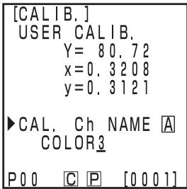
Setting screen
- Skip to step 12 if not setting a calibration channel name.
(How to set the calibration channel name)
1) Select input mode using the key.
- The input modes change in the following order: upper case Latin letters lower case Latin letters numbers.
2) Move the cursor using the key and input the color difference target color name using the numeric pad. - The name is up to 9 characters (see P.20 "As input keys" for details.)
12 Once settings are complete, press the Measure/Enter key Measure Enter
- Settings are complete, complete sound beeps and the display returns to the measurement screen.
This sets the multi-calibration function which corrects indicated values using both white calibration and user calibration data.
Note
When setting or canceling multi-calibration, you must set the color difference target color again.
The color difference target color is not corrected using user calibration performed after measurement.
See P.145 for details on multi-calibration.
- Multi-calibration cannot be set if white calibration and user calibration are not done ahead of time.
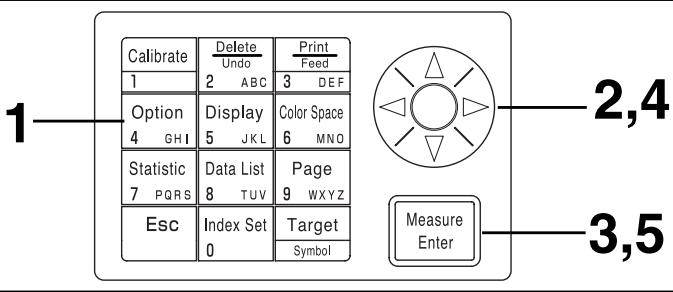
[Operating Procedure]
1 Press the Option key while in the measurement screen.
- The option selection screen appears.
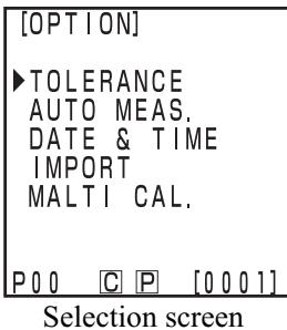
2 Select "MALTI CAL." using the key.
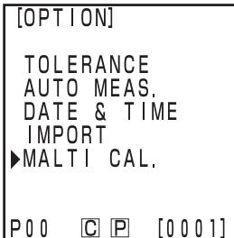
3 Press the Measure/Enter key Measure Enter
- The multi-calibration setting screen appears.
Item
ALL CHANNELS: Multi-calibration is set.
WHiTE CAL. TILE: When user calibration is not performed. (See P.86 "White Calibration")
Ch**: Manual select calibration is set (See P.137 "Setting the Mannul Select Calibration")
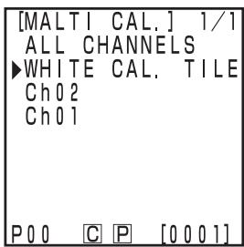
Selection screen
4 Select "ALL CHANNELS" using the key.
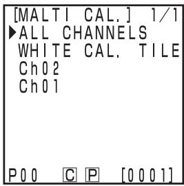
Press the Measure/Enter key Measure Enter
- Once multi-calibration settings are complete, the display returns to the measurement screen.
This sets the manual select calibration function which allows the user to select a calibration channel whose calibration data is to be used to correct indicated values.
Note
When setting or canceling manual select calibration, you must set the color difference target color again.
The color difference target color is not corrected using user calibration performed after measurement.
See P.145 for details on manual select calibration.
- Manual select calibration cannot be set if white calibration and selected user are not done ahead of time.
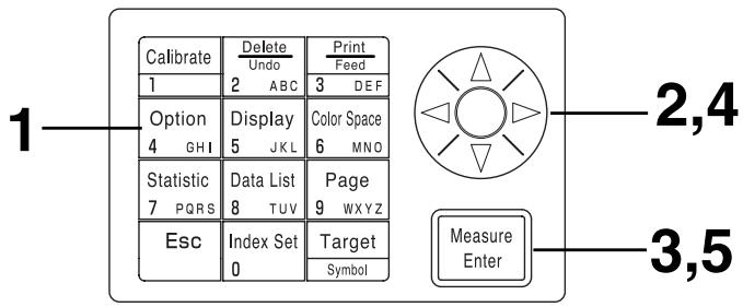
[Operating Procedure]
1 Press the Option key 4 0 + 1 while in the measurement screen.
- The option selection screen appears.
![KONICA CR-410 - [Operating Procedure] - 1](/content/2025/01/172144/images/f513f6db10ce8ffd03edc77b68dad9648cf6ce67c5790e562dbd95bd17483184.jpg)
Selection screen
2 Select "MALTI CAL." using the key.
![KONICA CR-410 - [Operating Procedure] - 2](/content/2025/01/172144/images/3b660f2c20596dbe697e23771977c110d82c2584462bda84fe4e6e7277e72ad3.jpg)
3 Press the Measure/Enter key Measure Enter
- The multi-calibration setting screen appears.
Item
ALL CHANNELS: Multi-calibration is set.
WHiTE CAL. TILE: When user calibration is not performed. (See P.86 "White Calibration")
Ch**: Manual select calibration is set (See P.137 "Setting the Manual Select Calibration")

Selection screen
4 Move the cursor using the key to and select a calibration channel.
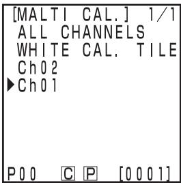
5 Press the Measure/Enter key Measure Enter
- Once manual select calibration settings are complete, the display returns to the measurement screen.
Note
Since settings for calibration channel made in manual select calibration are kept even if the power is turned OFF (O), it is important to check the calibration channel following steps 1 to 3 above in the following situations.
- When changing the calibration channel settings to measure a different color
- When the instrument has been left unused for long periods of time
The user calibration channel can be deleted as follows.
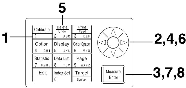
1 Press the Calibration key Calibrate while in the measurement screen.
- The calibration screen appears.
2 Select "USER CALIB." using the key.
Press the Measure/Enter key Measure Enter
- The user calibration list screen appears.
4 Select the calibration channel to delete using the key.
5 Press the Delete/Undo key 2 ABC
- The calibration data deletion selection screen will appear.
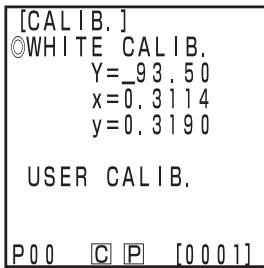
Calibration screen
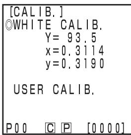
Calibration screen
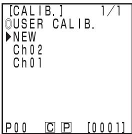
List screen
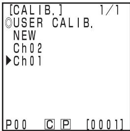
List screen
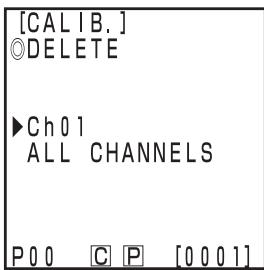
Selection screen
6 Select either one channel selected or "ALL CHANNELS" using the key.
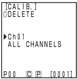
7 Press the Measure/Enter key Measure Enter
- The deletion screen for calibration appears.
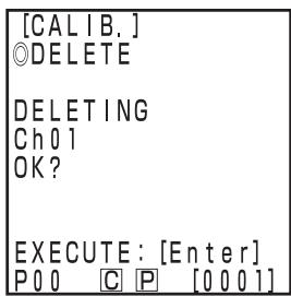
Only deleting the selected channel
8 Confirm the message and press the Measure/Enter key Measure Enter
- Once deletion is complete, complete sound beeps and the display returns to the measurement screen.
Note
White calibration is selected if the selected calibration channel is deleted.
(Method for changing user calibration channel name)
1) Use Steps 1-7 of the operating procedure "Setting the User Calibration Data" on P.132 to display the setting screen for the calibration channel to be changed.
- In Step 4, from the existing calibration channels, select the one you want to change the name of.
2) With the key, select "CAL. Ch NAME".
3) With the key, select the input mode.
- The input mode changes in the sequence: Upper case letters Lower case letters Numbers.
4) Move the cursor with the key and input the user calibration channel name you want with the number keys. - The name may be up to 9 characters long. (For details, see "As input keys" on P.20.)
5) When the setting is complete, press the Measure/Enter key Enter. - If the calibration channel name has been changed, measurement is not made even if the Measure/Enter key Measure Enter is pressed.
- After the settings are complete, the completion sound is made and the system returns to the measuring screen.
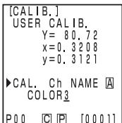
Chapter 4
-- Description --
Principles of Measuring
The measuring head measures a specimen, gets the color information from the specimen, converts it to one of the various display modes in the measuring head, and displays it. Also the data processor converts data to one of the various color space modes, displays it, and prints it.
The measuring head is divided into the specimen measuring part which measures the reflected light from the specimen and the monitoring illumination part which directly measures the light from the illumination light source. Each measuring part is equipped with sensors with equal color function _2 ( long wavelength side), , and responses, which are the spectral response for a standard observer and (this instrument uses a spectral response for a CIE 19312^ observer).
By measuring the illumination light source with the monitoring illumination part, it is possible to get data unaffected by subtle changes in the illumination light source.
The circuit offset influence is eliminated by applying the following formulas to the specimen measuring part measurement data (X2s^,Ys^,Zs^) and the monitoring illumination part measurement data (X2r^,Yr^,Zr^) gotten when illuminating, and the specimen measuring part measurement data (X2s^ , Ys", Zs") and the monitoring illumination part measurement data (X2r^ ,Yr^ ,Zr^ ) gotten when not illuminating.
$$ \left{ \begin{array}{l} \mathrm {X} _ {2} \mathrm {s} = \mathrm {X} _ {2} \mathrm {s} ^ {\prime} - \mathrm {X} _ {2} \mathrm {s} ^ {\prime \prime} \ \mathrm {Y s} = \mathrm {Y s} ^ {\prime} - \mathrm {Y s} ^ {\prime \prime} \ \mathrm {Z s} = \mathrm {Z s} ^ {\prime} - \mathrm {Z s} ^ {\prime \prime} \end{array} \right. \quad \left{ \begin{array}{l} \mathrm {X} _ {2} \mathrm {r} = \mathrm {X} _ {2} \mathrm {r} ^ {\prime} - \mathrm {X} _ {2} \mathrm {r} ^ {\prime \prime} \ \mathrm {Y r} = \mathrm {Y r} ^ {\prime} - \mathrm {Y r} ^ {\prime \prime} \ \mathrm {Z r} = \mathrm {Z r} ^ {\prime} - \mathrm {Z r} ^ {\prime \prime} \end{array} \right. $$
The following formulas eliminate the influence of subtle changes in the illuminant.
$$ \mathrm {X} _ {2} \mathrm {m} = \frac {\mathrm {X} _ {2} \mathrm {s}}{\mathrm {X} _ {2} \mathrm {r}} \quad \mathrm {Y m} = \frac {\mathrm {Y s}}{\mathrm {Y r}} \quad \mathrm {Z m} = \frac {\mathrm {Z s}}{\mathrm {Z r}} $$
_1 data is calculated by multiplying Zm by the constant.
$$ \mathrm {X} _ {1} \mathrm {m} = 0. 1 6 7 2 \cdot \mathrm {Z m} $$
$$ \therefore X m = X _ {1} m + X _ {2} m $$
The tristimulus value (X, Y, Z) are calculated by multiplying the data achieved from the above (Xm, Ym, Zm) by the calibration constant (, , ) .
$$ \left{ \begin{array}{l} X = \alpha \cdot X m \ Y = \beta \cdot Y m \ Z = \gamma \cdot Z m \end{array} \right. $$
These tristimulus value (X,Y,Z) can be converted to various different color spaces.
Illumination Optics of the CR-400
The CR-400 is designed in diffusion illumination 0^ viewing angle geometry (specular component included). This illumination method illuminates the specimen from all directions using illuminants with almost completely equal brightness, and receives the reflected light vertically from the specimen surface. Normally, when looking at color in, say, a department store or an office, the multiple light sources and the light reflected from the walls create diffused lighting conditions. Outside these conditions are also diffused, in this case from the sky, so this method creates realistic lighting conditions. This instrument is therefore very close to normal visual evaluation, and can be used with all types of specimen.
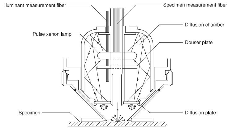
Illumination Optics of the CR-410
The CR-410 can measure wide range with a diameter of 50mm . It can also take average measurements of diffused reflected components with little regular reflection, such as cloth and carpets. It is useful when taking average measurements of relatively wide measurement surfaces, such as fibers, rugs, carpets, and blankets. As shown in the figure, the light from the pulse xenon lamp is diffused using a diffusion plate, and the light with is diffused evenly after passing through the diffusion plate illuminates the measurement surface with a large measurement diameter of 50mm . Of all the light which is reflected from the specimen surface, only that which is reflected vertically from the specimen surface is led through the specimen measurement fiber to the measuring head sensor, where it is calculated and displayed in the LCD as the measurement value. Caution is required here as this structure receives a lot of regular reflected components, so a lot light is received from specimens with flat surfaces, therefore greatly affecting the illuminant color.
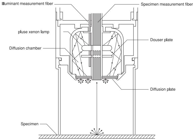
It is extremely difficult to perfectly match the spectral response three photoelectric tristimulus colorimeters like this instrument to the CIE 1931 standard observer, creating a slight discrepancy in spectral response. (See Figure.)
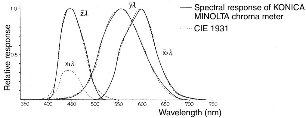
CIE 1931 colorimetric standard Observer curves and spectral response of KONICA MINOLTA chroma meter
In color difference measurement, the effects of this slight discrepancy in spectral response is within the scope of measurement accuracy, so it does not present a problem. However, in color measurement, depending on the color of the specimen to be measured, there are times when a slight discrepancy with the value (true value) gotten when measuring using an ideal prism response. There might even appear a similar discrepancy in spectral response when performing measurements using two of the same model instrument, creating discrepancies in the assigned values when using multiple instruments.
When this happens, it is possible to minimize the discrepancy in assigned value by using the user calibration function.
The user calibration is set by measuring a target specimen with a known sensitivity ahead of time and setting this value as a calibration target color in a calibration channel (ch 01-19). This calibration data is then used to correct the assigned value when measuring
Thereby almost the discrepancy eliminates completely in the assigned value when measuring a color close to the target specimen color. This also applies to colors which are far from the target specimen color.
There are two ways of user calibration: the multi-calibration function and the manual select calibration function. Choose whichever is most appropriate for the number or type of colors to be measured.
The multi-calibration function is used to correct the assigned value using the calibration data in all the set calibration channels. It is therefore effective in providing an appropriate correction not only for the vicinity of the calibration target point but also for the value around it.
However, since the correction effect becomes smaller for colors further from the calibration target point, more effective correction can be achieved by selecting a calibration target color which envelops the color to be measured.
This function is useful in the following cases.
1) When measuring many different colors
The narrower the region where the calibration target point is placed is, the greater the multi-calibration effect is.
2) When measuring only certain colors
Setting the optional calibration target color to envelope the color to be measured will achieve a greater multi-calibration effect.
Note
Multi-calibration corrects the measurement value using the calibration data for all set calibration channels. After measuring using the multi-calibration function, adding to or changing the calibration channels will create a discrepancy with the measurement value, even if the same specimen is measured. Note also that color difference target color values which are corrected during measurement do not change thereafter.
Even more accurate correction can be achieved by creating a list of target colors for the same material as the measurement specimen and calibrated by the master body.
The manual select calibration allows the user to select any calibration channel to correct assigned values using only that calibration data in that calibration channel.
A list of the target colors for calibration should be made for the same material as the measurement specimen and attached to the master body.
This function is useful in the following cases.
- When measuring only the same hue
In this case, it is possible to select a color for the user calibration target color which is similar to the measured color.
It is possible to minimize the difference (inter-instrument agreement) in the assigned values between instruments by performing optional calibration as described below, when using multiple instruments.
- When there is a target specimen which is already valued and which is close to the color of the specimen to be measured.
1) Perform user calibration all bodies with the target specimen using the data for the target specimen which is already valued. - When there is not a target specimen which is already valued and which is close to the color of the specimen to be measured.
1) Select a master body.
2) Measure a specimen which is close to the color to be measured using the master body.
3) Perform user calibration all other bodies with that specimen. (Calibration data uses measurement data by the master body.)
The keys will not function if pressed when the error message is displayed.
| Message | Symptom/Possible Cause | Corrective Acrion |
| ER00 COMMUNICATION ERROR | Communication performed with inappropriate command. • Cable unplugged during communication • Message garbled by external noise, etc. | • Plug in cable with the power OFF. • Use a lower baud rate if noise is the problem. |
| ER01 MEMORY FULL | [Measuring Head] 1. Number of measurement data exceeds 1000. 2. Number of target color data exceeds 100. [Data Processor] 3. Number of measurement data exceeds 2000. 4. Number of pages exceeds 100. 5. Number of target color data exceeds 100. 6. Number of user calibration channels exceeds 19. 7. There is insufficient room to transfer all data to the data processor when importing measurement data. | 1. Connect to data processor and transfer data there to free up some space, or turn OFF the data protection setting. 2. Overwrite unnecessary target colors when registering. Or create more space by connect- ing to the Data Processor and deleting any unnecessary target colors. 3,4. If you turn OFF data protect, the oldest pages will automatically be updated. Or you can delete some data to free up some space. 5. Overwrite onto unneeded target colors or de- lete some to free up space. 6. Overwrite onto unneeded channels or delete some to free up space. 7. Delete some pages or data to free up space. |
| ER02 LOW BATTERY | Battery voltage drop | • Turn OFF the power and replace batteries or use the AC adapter. |
| ER05 ERROR IN FLASHING | Xenon lamp does not flash properly. • Xenon lamp has malfunctioned. • Flash circuit has malfunctioned. • Faulty sensor | • Repeat measurement. • If the problem persists, contact your nearest Konica Minolta authorized service facility. |
| ER06 OVERFLOW | Because of the excessively high reflectivity of the measurement specimen, the operation of measurement data exceeds the performance of the instrument. When Y is higher than 160: | • Redo white calibration and the measurement. • If the problem persists, contact your nearest Konica Minolta authorized service facility. |
| ER07 WHITE CALIBRATION INCOMPLETE | White calibration has not been performed. | • Perform white calibration. |
| ER08 COMMUNICATION ERROR | An overrun or other type of error occurred dur- ing communication. • Cable unplugged during communication • Calibration, target color, or option settings changed on the data processor without hook- ing it up to the measuring head. | • Plug in cable with the power OFF. • Change calibration, target color, or option settings using the Measuring Head. |
| ER10 NO DATA IN MEMORY | The data needed for that function to work is not found. • Attempting to print or delete nonexistent data • Statistical operations or list displays in pages without data | • Store some data before attempting |
| Message | Symptom/Possible Cause | Corrective Arcion |
| ER12 SAMPLE TOO DARK | Low reflectivity of measurement specimen means there is not enough light coming off the specimen for measurement. | • Redo the white calibration and the measurement. • If the problem persists, contact your nearest Konica Minolta authorized service facility. |
| ER13 ERROR IN A/D | A/D conversion failed. • The A/D converter is broken. • Circuit the peripherals is broken. | • Repeat measurement. • If the problem persists, contact your nearest Konica Minolta authorized service facility. |
| ER17 INCORRECT CLOCK OPERATION | Clock IC is not working correctly. • Clock IC power voltage drop or breakdown of circuits relating to the clock IC. | Insert batteries again. • If the problem persists, contact your nearest Konica Minolta authorized service facility. |
| ER27 ERROR IN CHARGING | Failed to supply power to the flash circuit. • The flash circuit is broken. • Power voltage drop | When using the batteries, turn OFF the power and replace new ones. |
| ER30 LOW BACK UP BATTERY VOLTAGE | Data has been deleted because the memory backup batteries are low. | Recharge the backup battery for the memory by turning ON the power switch. A full charge is achieved in 20 hours and will last for approximately 10 months. |
| DATA SET ERROR | 1. The data entered is outside the data set range. • Color space and data name have been entered which is not within the range that can be processed by the instrument. • Incorrect date entered. 2. Attempt to change to a light source that cannot be used for the current color space. | 1. overrun data. 2. If the light source cannot be set up although the initial setting is completed, select a color space available with the light source, and then change the light source setting. |
| NO TARGET COLOR | No target color has been set. | • Repeat after setting a target color. |
| USE ANOTHER COLOR SPACE | The function being attempted does not work with the current color space. • Statistical operations with Munsell or user indexes • Target color operations when using Munsell • Manual input of target values when using L*C*h, LCh99, WI/Tw, WI, YI, CMC, CIE1994, or CIE2000. | • Re-attempt after changing to a different color space. |
| NO PAPER | The printer has run out of paper. | • Insert the paper. • Turn the printer setting OFF. |
| DATA PROTECT IS VALID | Since the data protection setting is ON, the function being attempted is restricted. • Page deletion is impossible. | • Turn OFF the data protection setting before deleting the page. • Oldest measurement data is overwritten if the data protection setting is turned OFF. |
| OK02 LOW ILLUMINATION | The xenon arc lamp has dropped to below 65% of new illumination. • The xenon arc lamp has gotten old. • The diffusion chamber has gotten dirty. | • If the problem persists, contact your nearest Konica Minolta authorized service facility. |
| OK05 DIFF. ILLUMINATIONS CAN'T COMMUNICATE | The illumination settings for the measuring head and the data processor are different. | Initialize them and change the illumination settings. |
If anything goes wrong with the instrument, take the appropriate steps shown in the table below. If the instrument still does not work properly, turn the power OFF, and then turn it ON again. If the symptom persists, contact your nearest Konica Minolta authorized service facility.
| Symptom | Check Point | Action |
| Blank LCD on measuring head | Is the power switch ON? | Turn the power switch ON, or if the data processor is hooked up, turn the power switch on the data processor ON. |
| Are the batteries inserted? Is the AC adapter connected? | When using the measuring head alone, insert batteries or connect the AC adapter. | |
| Is displayed? | Replace the batteries with new ones or connect the AC adapter. | |
| Is the LCD contrast appropriate? | Adjust the LCD contrast.<Adjustment when the screen is not visible>See P.28 “LCD Display, Communication and Other Settings.”Keeping the ENTER key pressed immediately after turning the instrument on automatically puts the instrument in contrast adjustment mode, and repeatedly brighten and darken the display.Bright→Dark 1→12↑ | |
| Has the boot switch been touched? *Not to be touched under any circumstances. | Return to its original position. | |
| Blank LCD on data processor | Are the batteries inserted? Is the AC adapter connected? | Turn the power switches on the measuring head and the data processor both ON.* The measuring head does not supply power to the data processor. |
| Is displayed? | Replace the batteries with new ones or connect the AC adapter. | |
| Is the LCD contrast appropriate? | Adjust the LCD contrast.See P.69 “Adjusting the Contrast of the LCD”. | |
| The ready lamp on the measuring head does not come ON. | Is displayed? | Replace the batteries with new ones. |
| Has the machine been left untouched for 3 minutes? | Touch one of the keys. | |
| The measurement button has no effect. | Is the instrument either in the middle of measuring or printing? | Try again after it is finished. |
| Is the measurement screen displayed? | Try again in the measurement screen. | |
| Is the data list screen displayed? | Press the Escape key twice to return to the measurement screen. | |
| There are variation in the measurement data. | Is the measuring head placed vertically above the specimen? | Placed the instrument vertically not to leak light. |
| Is the measuring head moving during measurement? | Do not move the instrument during measurement. | |
| Is the calibration channel changed when using the multi-calibration function. | Use only the same calibration channel. | |
| Does not print. | Is the roll paper thermal paper? | Use the optional thermal paper. |
| Is the paper inserted upside down? | Insert the paper correctly. | |
| Is the printer set to ON? | If not, set it to ON. | |
| Prints slowly. The print is faint. | Are ▲ or □ displayed? | Replace the batteries with new ones or connect the AC adapter. * Low voltage becomes slow printing. |
| Are you using the printer at low temperature? | Use lithium or nickel metal hydride batteries. * The battery power of alkali batteries drips in low temperature environments. | |
| Data output to PC not possible. No commands from PC are accepted. Commands cannot be accepted correctly. | Is the RS-232C cable connected correctly? | Connect the instrument properly using our RS-232C cable (standard accessory) between the instrument's RS-232C terminal and the PC's RS-232C connector. |
| Is the RS-232C cable standard accessory? | ||
| Are the communication settings of the instrument and a PC appropriate? | Set the PC's communication settings for the in-strument. | |
| Is the PC mode screen displayed (or the remote mode screen for the data processor)? | Change to the PC mode screen (or the remote mode screen for the data processor). | |
| Measuring head and data processor cannot communicate. | Are the power switches on the measuring head and the data processor both ON? | Turn the power switches on the measuring head and the data processor both ON? |
| Is the RS-232C cable standard accessory? | Use our RS-232C cable (standard accessory). | |
| Did you connect the cable or the AC adapter with the power ON? | Turn the power OFF before connecting. |
| Name | Chroma Meter Measuring Head | |
| Model | CR-400 Head | CR-410 Head |
| Illuminating/viewing system | d/o Diffuse illuminating/0° viewing (speculer component included) | Wide-area Diffuse illuminating/0° view-ing (specular component included) |
| Detector | Silicone photo cells (6) | |
| Display range | Y: 0.01 to 160.00% (reflectance) | |
| Light source | Pulsed xenon lamp | |
| Measurement time | 1 sec. | |
| Minimum measurement interval | 3 sec. | |
| Battery performance | Approx. 800 measurements (when using batteries under company testing KONICA MINOLTA's conditions) | |
| Measurement/illumination area | φ8/φ11 | φ50/φ53 |
| Repeatability | Within ΔE*ab0.07 standard deviation (when the white calibration plate was measured 30 times at intervals of 10 seconds) | |
| Inter instrument agreement | ΔE*ab: within 0.6 | ΔE*ab: within 0.8 |
| Average of 12 BCRA series II colors | ||
| Observer | Closely matches CIE 1931 Standard Observers: (x2λ, yλ, zλ) | |
| Illuminant | * C, D65 | |
| Display | * Chroma values, color difference values, color difference graphs, PASS/WARN/FAIL display | |
| Tolerance judgment | * Color difference tolerance (box tolerance and elliptical tolerance) | |
| Color space/colorimetric data | * XYZ, Y x y, L*a*b*, Hunter Lab, L*C*h, Munsell (only illuminant C), CMC (l:c), CIE1994, Lab99, LCh99, CIE2000, CIE WI-Tw (only illuminant D65), WI ASTM E313 (only illuminant C), YI ASTM D1925 (only illuminant C), YI ASTM E313 (only for illuminant C), User index (up to six can be registered from computer) | |
| Languages | Operating keys: English * LCD: English (default), German, French, Italian, Spanish, Japanese | |
| Storable data sets | 1000 (measuring head and data processor save different data) | |
| Color difference target colors | 100 | |
| Calibration channels | * 20 channels (ch00: white calibration, ch01 to ch19: user calibration) | |
| Display | Dot-matrix LCD with back light (15 chars x 9 lines + 1 line for icon display) | |
| Interface | RS-232C compliant (for data processor/PC) * Baud rate: 4800, 9600, 19200 (bps), set at 9600 bps when shipped from factory | |
| Power source | 4 AAA size alkali or Ni-MH batteries AC adapter (AC-A17) AC120V ~ 50-60Hz 0.4A (for N.America) AC230V ~ 50-60Hz 0.4A (for worldwide except N.America) | |
| Size | 102(W) x 217(H) x 63(D)mm | 102(W) x 244(H) x 63(D)mm |
| Weight | Approx. 550g | Approx. 570g |
| (including 4 AAA size batteries and not including RS-232C cable) | ||
| Operating temperature/humidity range (*1) | 0 to 40°C, relative humidity 85% or less (at 35°C) with no condensation | |
| Storage temperature/humidity range | -20 to 40°C, relative humidity 85% or less (at 35°C) with no condensation | |
| Other | LCD back light ON/OFF function (when ON, back light stays ON for 30 seconds after last key or measurement operation) | |
| Standard accessories | White calibration plate CR-A43 Protective cap CR-A72 | White calibration plate CR-A44 Protective cap CR-A104 |
| Wrist strap CR-A73, AC adapter AC-A17, 4 AAA size batteries | ||
| Optional accessories | Hard case CR-A103, RS-232C cable (for PC) CR-A102, Granular attachment CR-A50, CR-400 utility software CR-S4w, Color data software ChromaMagic CR-S3w | |
| Glass light projection tube CR-A33a, A33f Light projection tube CR-A33c, A33d Pivoting base CR-A12 Color tiles | Glass light projection tube A33e | |
- indicates when connected to the Data Processor or when not set using the Data Processor or the optional software, that some of the function are not available when the measuring head is not connected.
| Name | Data Processor |
| Model | DP-400 |
| Display range | Y: 0.01 to 160.00% (reflectance) |
| Measurement time | * 1 sec. |
| Minimum measurement interval | * 3 sec. |
| Battery performance | Approx. 800 measurements (when using batteries under company testing KONICA MINOLTA's conditions) |
| Illuminants | C, D65 |
| Display | Chroma values, color difference values, color difference graphs, PASS/WARN/FAIL display |
| Tolerance judgment | * Color difference tolerance (box tolerance and elliptical tolerance) Only for the display function |
| Color space/colorimetric data | * XYZ, Y x y, L*a*b*, Hunter Lab, L*:C*h, Munsell (only illuminant C), CMC (l:c), CIE1994, Lab99, LCh99, CIE2000, CIE WI-Tw (only illuminant D65), WI ASTM E313 (only illuminant C), YI ASTM D1925 (only illuminant C), YI ASTM E313 (only illuminant C), User index (up to six registered in the Measuring Head can be used) |
| Languages | Operating keys: English LCD : English (default), German, French, Italian, Spanish, Japanese |
| Storable data sets | Max. 2000 pieces of data (divisible into 100 pages) Deletion and Undoing selected stored data (one piece of data or all data) are possible |
| Color difference target colors | * Only for the operating function (100 pieces of data when the measuring head is connected; input of measurement values or numeric) (independent of page function) |
| Calibration channels | * Only for the operating function (20 channels when the measuring head is con- nected) (ch00: white calibration; ch01 to ch19: user calibration) |
| Page function | 100 pages |
| Display | Dot-matrix LCD with back light (16 chars x 9 lines + 1 line for icon display) Contrast adjustment |
| Printer | 384 dot line thermal printer (can also print graphs) Automatically prints out all measurement results (can be set not to) |
| Statistical function | Maximum, minimum, average, and standard deviation |
| Automatic measurement | * Date and time display: year, month, day, hour, minute Timer: 3sec. to 99 min. (Some measurement modes require more than 3 sec.) |
| Interface | RS-232C compliant Baud rate (bps): 19200 fixed (when connected to PC) When measuring head is connected baud rate is automatically set to that of the measurement head |
| Power source | 4 AA size alkali or Ni-MH batteries AC adapter (AC-A17) AC120V ~ 50-60Hz 0.4A (for N.America) AC230V ~ 50-60Hz 0.4A (for worldwide except N.America) |
| Size | 100(W) x 73(H) x 255(D)mm |
| Weight | Approx. 600g (not including batteries and paper) |
| Operating temperature/ humidity range (*1) | 0 to 40°C, relative humidity 85% or less (at 35°C) with no condensation |
| Storage temperature/humidity range | -20 to 40°C, relative humidity 85% or less (at 35°C) with no condensation |
| Other | * User calibration function (multi-calibration/manual calibration) Measurements for automatic average function Print ON/OFF function * CR-400 measurement data import function All color space print ON/OFF function Data protection ON/OFF function Back light ON/OFF function Buzzer ON/OFF function Displayed color limit function Remote mode (stored data output) Character input function (alphanumeric) |
| Standard accessories | Roll paper (1 roll), RS-232C cable (for Head-DP) CR-A101, AC adapter AC-A17, 4 AA batteries |
| Optional accessories | Shoulder strap SS-01, Hard case CR-A103, Roll paper (5 rolls) DP-A22, RS-232C cable (for PC) CR-A102, CR-400 utility software CR-S4w, Color data software ChromaMagic CR-S3w |
- indicates that part of or all functions are not available when the measurement head is not connected.
(Unit: mm)
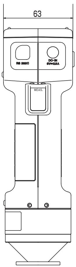
CR-400 Head
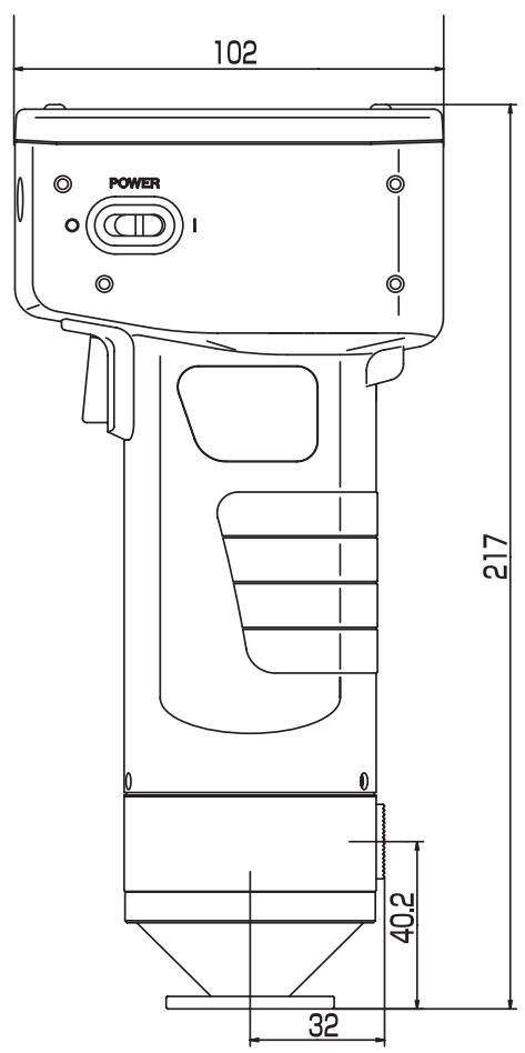
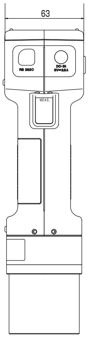
CR-410 Head
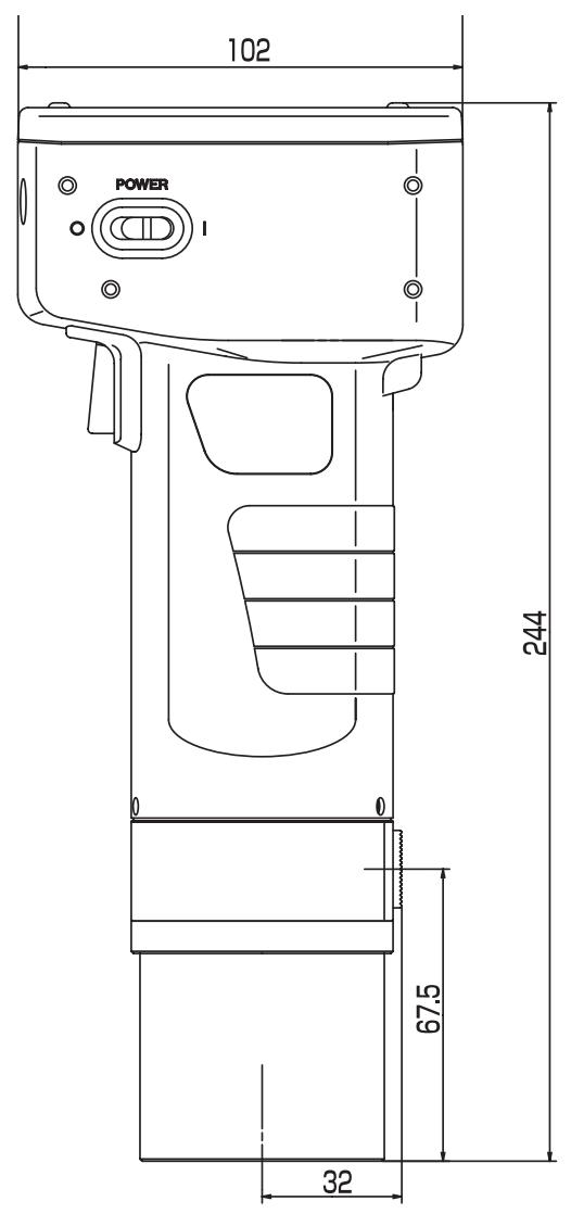
(Unit: mm)
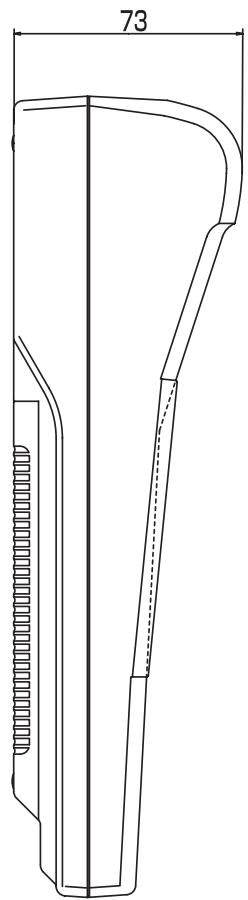
DP-400
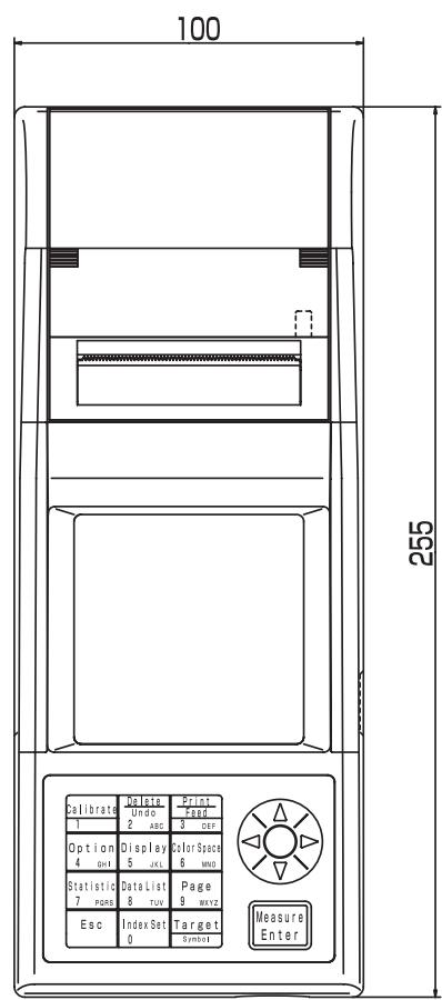
| T00 | [0003] |
| L* = 89.21 | |
| a* = 1.79 | |
| b* = 15.21 | |
| ΔL* = -0.01 | |
| Δa* = +0.05 | |
| Δb* = +0.17 | |
| ΔE* = 0.18 | |
| C | 1 |
| MINOLTA | [0001] |
| L* = 74.72 | |
| a* = 15.32 | |
| b* = 10.21 | |
| ΔL* = +0.11 | |
| Δa* = -0.01 | |
| Δb* = +0.13 | |
| ΔE* = 0.18 | |
| C | 1 |
Nombre de la différence de color respecto al patron
3 Pulse la tecla Target Color Target Symbol
Pulse la tecla Measure/Enter Measure Enter.
$$ \therefore X m = X _ {1} m + X _ {2} m $$