USER MANUAL CM-2600D KONICA
Spectrophotometer CM-2600d/2500d

Instruction Manual

The following symbols are used in this manual to prevent accidents which may occur as a result of incorrect use of the instrument.

Denotes a sentence regarding a safety warning or note. Read the sentence carefully to ensure safe and correct use.

Denotes a prohibited operation. The operation must never been performed.

Denotes an instruction.
The instruction must be strictly adhered to.

Denotes a prohibited operation. Never disassemble the instrument.

Denotes an instruction. Disconnect the AC power cord from the AC outlet.
Notes on this Manual
- Copying or reproduction of all or any part of the contents of this manual without KONICA MINOLTA SENSING's permission is strictly prohibited.
- The contents of this manual are subject to change without prior notice.
- Every effort has been made in the preparation of this manual to ensure the accuracy of its contents. However, should you have any questions or find any errors, please contact a KONICA MINOLTA SENSING -authorized service facility.
- KONICA MINOLTA SENSING will not accept any responsibility for consequences arising from the use of the instrument.
Safety Precautions
To ensure correct use of this instrument, read the following points carefully and adhere to them. After you have read this manual, keep it in a safe place where it can be referred to anytime a question arises.
| WARNING (Failure to adhere to the following points may result in death or serious injury.) |
| Do not use the instrument in places where flammable or combustible gases (gasoline etc.) are present. Doing so may cause a fire. | Do not disassemble or modify the in-strument or the AC adapter. Doing so may cause a fire or electric shock. |
| Always use the AC adapter supplied as a standard accessory or the optional AC adapter, and connect it to an AC outlet of the rated voltage and frequency. If the AC adapters other than those specified by KONICA MINOLTA SENSING, this may result in damage to the unit, fire or electric shock | The instrument should not be operated if it is damaged or AC adapter is damaged, or if smoke or odd smells occur. Doing so may result in a fire. In such situations, turn the power OFF immediately, disconnect the AC adapter from the AC outlet (or remove the batteries if they are used) and contact the nearest KONICA MINOLTA SENSING-authorized service facility. |
| If the instrument will not be used for a long time, disconnect the AC adapter from the AC outlet. Accumulated dirt or water on the prongs of the AC adapter's plug may cause a fire and should be removed. | Do not insert or disconnect the AC adapter with wet hands. Doing so may cause electric shock. |
| Take special care not to allow liquid or metal objects to enter the instrument. Doing so may cause a fire or electric shock. Should liquid or metal objects enter the instrument, turn the power OFF immediately, disconnect the AC adapter from the AC outlet (or remove the batteries if they are used), and contact the nearest KONICA MINOLTA SENSING-authorized service facility. | Do not dispose of batteries in fire, short their terminals, apply heat to them, or disassemble them. Also, do not recharge them (if they are not chargeable). Doing so may cause explosion or heat generation, resulting in fire or injury. |
| CAUTION (Falling to adhere to the following points may result in injury or damage to the instrument or other property.) |
| Do not perform measurement which the measurement aperture directed towards your face. Doing so may damage them. | Do not place the instrument on an unstable or sloping surface. Doing so may result in its dropping or overturning, causing injury. Take care not to drop the instrument when carrying it. |
| Do not use batteries other than those specified by KONICA MINOLTA SENSING. When installing batteries in the instrument, make sure that they are correctly oriented according to the (+) and (-) marks. Failure to adhere to these instructions may cause batteries to explode or leakage of electrolyte, resulting in fire, injury or air pollution. | When using the AC adapter, make sure that the AC outlet is located near the in-strument and that the AC adapter can be connected to and disconnected from the AC outlet easily. |
- This instrument and the AC adapter supplied as a standard accessory have been designed exclusively for indoor use.
- Do not leave the CM-2600d/2500d in direct sunlight or near sources of heat, such as stoves etc. The internal temperature of the instrument may become much higher than the ambient temperature in such cases.
- Do not use the CM-2600d/2500d in areas where dust, cigarette smoke or chemical gases are present. Doing so may cause deterioration in performance or breakdown.
- Do not use the CM-2600d/2500d near equipment which produces a strong magnetic field (such as speakers etc.)
- The CM-2600d/2500d belongs to installation category II products (equipment which is powered by an AC adapter connected to a commercially available power).
- The CM-2600d/2500d belongs to pollution level 2 products (equipment which may cause temporary electrical hazards due to contamination or condensation or products which are used in such an environment).
- Do not use the CM-2600d/2500d at altitudes of higher than 2000m .
- Use this instrument at ambient temperature between 5 and 40^ and relative humidity 80% or less (at 35^ ) with no condensation (^*1) . Operating this instrument outside specified temperature and humidity range may unsatisfy its original performance.
*1 Operating temperature/humidity range of products for North America: between 5 and 40^ and relative humidity 80% or less (at 31^ ) with no condensation
- When using the instrument upside-down, make sure no dirt or dust get into the aperture.
- When using the instrument for long periods of time, the displayed value may change depending on changes in the environment. Therefore, in order to achieve accurate measurements, we recommend that white calibration be done regularly using the White Calibration Plate.
- The calibration data for the White Calibration Plate was measured at 23^ . To achieve the highest accuracy when measuring absolute values (colorimetric values), calibration and measurement should be performed at 23^ .
- Do not allow the White Calibration Plate to get scratched or stained.
- If you are not going to use the White Calibration Plate, attach the cap to the White Calibration Plate to prevent entry of ambient light.
- Do not touch the Target Mask's inner surface by hand, scratch it or make it dirty.
- When the Target Mask is not in use, install it on the White Calibration Plate (CM-A145) to prevent exposure to external light.
- When removing the "Measuring Base", make sure that the screws used to attach the base to the instrument are stored properly and are not mislaid. If the screws do become misplaced, use M3 cross-headed screws that are 4 to 5mm long as replacements. (For details, see page E-16.)
- Do not tighten the screws too tightly when attaching the "Measuring Base". This could damage the "Measuring Base" or the instrument itself.
- Remove the "Measuring Base" before using the optional Zero Calibration Box or Dust Cover Set.
- Make sure that the power switch is set to OFF ("O") when the CM-2600d/2500d is not in use.
- Always use the AC adaptor (AC-A17) supplied as a standard accessory and connect it to an AC outlet of the rated voltage and frequency. Use the AC power supply voltage of the rated supply voltage (within ± 10% ).
- Do not subject the CM-2600d/2500d to strong impact or vibration. Doing so may cause deterioration in performance or breakdown.
- Since the specimen measuring port and integrating sphere are extremely precise optical components, great care should be taken to prevent them getting dirty or exposing them to impact. If you are not going to use the CM-2600d/2500d, put it on the White Calibration Plate (CM-A145).
- The CM-2600d/2500d may cause interference if used near a television, radio, etc.
- Since the CM-2600d/2500d uses a microcomputer, the LCD may go blank if it is exposed to strong static electricity. In this case, turn the power OFF, then turn it ON again. If black smudges appear on the LCD, wait until they disappear naturally.
- When turning the power OFF and then ON again, wait several seconds after turning the power OFF.
- Measured data and various settings are stored in the memory backed up by batteries. The backup batteries are automatically charged during operation of this instrument, and can retain the contents of the memory for 4.5 months if they have been fully charged. At the time of purchase, the backup battery may not be fully charged. To charge the backup battery, set the power switch to ON. Charging of the backup battery is performed continuously while the instrument is switched on, even while the instrument is being used. Full charging is completed in 25 hours, and there is no danger of overcharging.
- It is recommended to keep a backup of your important data in another recording medium using optional Color Data Software (sold separately).
Note
- The backup batteries' model number is VL2020 (3V).
- Do not try to replace the backup batteries by yourself. Contact a KONICA MINOLTA SENSING-authorised service facility.
Notes on Storage
- The CM-2600d/2500d should be stored at temperatures between 0^ and 45^ , and at a relative humidity of 80% or less (35^) , without condensation. Do not store the instrument in areas subject to high temperatures, high humidity, sudden changes in temperature, or where freezing or condensation may occur, because these circumstances may cause breakdown. It is more reliable to store the CM-2600d/2500d with a drying agent (such as silica gel) at a temperature around 20^ .
- Do not leave the CM-2600d/2500d inside a car such as in the cab or trunk. Otherwise, the temperature and/or humidity may go leave the allowable range for storage during midsummer or midwinter, resulting in breakdown.
- Keep the packing materials used for shipment and use it to transport the CM-2600d/2500d. This protects the instrument from sudden changes in temperature, vibration, and shock.
- Do not store the CM-2600d/2500d in areas where dust, cigarette smoke or chemical gases are present. Doing so may cause deterioration in performance or breakdown.
- Entry of dust into the measuring aperture will hinder accurate measurement. Block the measuring port to prevent entry of the dust.
- The White Calibration Plate may become discolored if left exposed to light. Therefore, make sure that the lid is closed to prevent entry of ambient light when it is not in use.
- The Target Masks may discolor if they are left exposed to light. When they are not in use, keep them in a safe place to prevent exposure to light and to protect them from scratches and dust.
- Be sure to keep all packing materials (cardboard box, cushioning material, plastic bags, etc.). They can be used to protect the instrument during transportation to service facility for maintenance (re-calibration etc.).
- If you are not going to use the CM-2600d/2500d for more than two weeks, the batteries must be removed. If the batteries are left in the instrument, leakage may occur resulting in damage to the instrument.
Notes on Cleaning
- If the CM-2600d/2500d becomes dirty, wipe it with a soft, clean dry cloth. Never use solvents such as thinner and benzene.
- If the White Calibration Plate becomes dirty, wipe it gently with a soft, clean dry cloth. If dirt is difficult to remove, contact the nearest service facility listed on the attached sheet.
- If the inner surface of the Target Masks or the inside of the integrating sphere get dirty, contact a KONICA MINOLTA SENSING-authorized service facility.
- Should the CM-2600d/2500d break down, do not try to disassemble and repair it by yourself. Contact a KONICA MINOLTA SENSING-authorized service facility.
Contents
Safety Precautions E-1
Notes on Use E-2
Notes on Storage. E-3
Notes on Cleaning. E-4
Conventions 8
Chapter 1 Before Using the Instrument
Accessories. E-10
Standard Accessories E-10
Optional Accessories E-11
Names and Functions of Parts. E-12
Preparation E-14
Attaching/Removing a Target Mask. E-14
Attaching/Removing the "Measuring Base" E-16
Cleaning Each Part. E-17
Inserting the Batteries E-18
Connecting the AC Adapter. E-19
Turning Power ON. E-20
Turning Power OFF. E-20
System Configuration. E-21
Items You Must Know E-22
Language Mode E-22
Measurement Mode E-22
Target Modes. E-23
Screen Display E-23
Battery Alarm E-23
Data Saving. E-23
Chapter 2 Preparation for Measurement
Flow of Measurement. E-26
Turning Power On for the First Time. E-27
Setting the Language Mode and Measurement Mode E-27
Selecting the Target Mode. E-28
Initial Setting. E-29
Setting the Date and Time E-30
Setting the Display Direction. E-31
Setting the LCD Contrast. E-32
Selecting a Measurement Condition E-33
Setting a Measurement Condition E-34
Setting the Measurement Area and Specular Component Mode. E-35
Setting the UV. E-36
SelectingIlluminant1 E-36
SelectingIlluminant2 E-37
Selecting the Observer. E-37
Selecting the Display Mode. E-38
Selecting a Color Space. E-39
Setting the Number of Measurements for Manual Averaging. E-40
Setting the Standard Deviation for Manual Averaging. E-40
Setting the Number of Measurements for Auto Averaging. E-40
Setting the Delay Time. E-41
Zero Calibration E-44
White Calibration. E-46
Setting a Color Difference Target Data. E-48
Selecting a Color Difference Target Data E-50
Deleting a Color Difference Target Data. E-51
Setting Color Difference Tolerances E-52
Box Tolerance. E-52
Elliptical Tolerance. E-55
Chapter 3 Measurement
Measurement. E-64
Displaying the Measurement Results. E-66
Measured Data. E-66
Pass/Fail Judgment E-67
Color Difference Graph E-68
Spectral Reflectance Graph E-69
Assessments E-70
Switching the Display Contents of the Measurement Results. E-72
Deleting Measured Data E-74
Abbreviations on LCD Display E-76
Measurement Results for "linked to each data." E-77
Chapter 4 Other Functions
Measuring the Average 80
Manual Averaging E-80
Auto Averaging. E-82
Pass/Fail Judgment for Color Difference E-83
Pass/Fail Judgment Based on Box Tolerances E-83
Pass/Fail Judgment Based on Elliptical Tolerances E-85
Assessments E-87
Assessment by Box Tolerances E-87
Assessment by Elliptical Tolerances E-89
Connecting to an External Device. E-92
Connecting a Personal Computer E-92
Outputting to a Printer E-95
TASK Mode E-101
What is TASK Mode? E-101
Downloading a Task. E-101
Performing Measurement in TASK Mode. E-102
Chapter 5 Troubleshooting
Error Messages E-110
Troubleshooting E-112
Chapter 6 Appendix
Principles of Measurement E-116
Illuminating/Viewing System E-116
Illumination Area and Measurement Area. E-117
Simultaneous SCI/SCE Measurement E-118
UV Control E-118
Target Mode. E-119
Relation Between Measured Data and Target Color. E-119
Deleting a Color Difference Target Data. E-119
Notes on Changing the Target Mode. E-119
Specifications. E-123
Dimensions E-125
Menu Structure. E-126
Reading the menu structure diagram E-126
Menu Structure diagram E-127
Conventions
This manual describes how to setup the CM-2600d/2500d which the firmware version is 1.40 or higher and use it to take measurements.
- Organization
The CM-2600d/2500d (Ver. 1.30 or higher) supports two types of the target mode, "linked to each data." and "defined in COND."; the procedure and details for these types varies slightly.
This manual describes the procedures for the default target mode, which is "linked to each data." It only includes information for the "defined in COND." mode where it differs from the default.
- Page layout
Symbols used in this manual are explained below.
*Note that the page shown in the illustration is for explanatory purposes only, and is not an actual page from this manual.
For the version of the instrument firmware
The version of the instrument firmware can be confirmed on the screen which is displayed first after switching power on.
Chapter 1
Before Using the Instrument
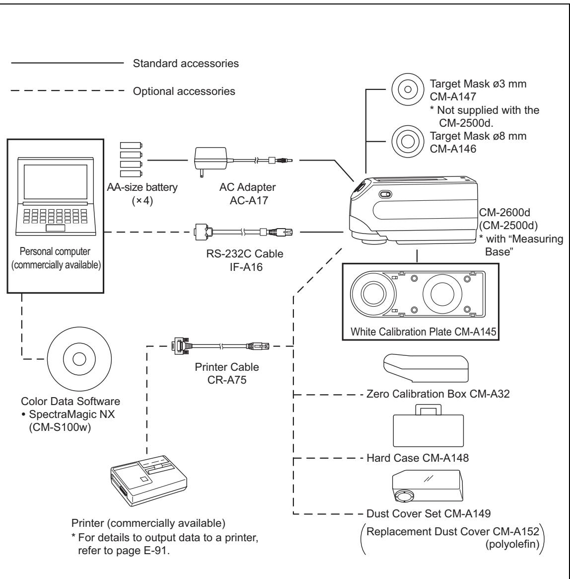
Standard and optional accessories are available with the instrument.
Standard Accessories
Make sure that all the following items are present.
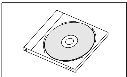
White Calibration Plate CM-A145
Used to perform white calibration.
A data disk containing white calibration data is supplied with this accessory.
Memo
- This accessory can be used as a table on which to store the CM-2600d/ 2500d.
- In the case of the CM-2600d, a Target Mask that is not in use can be stored on this accessory.
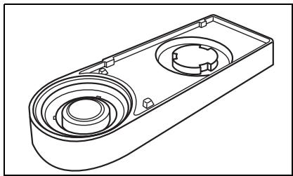
Target Mask
CM-A146 (for 8mm CM-A147 (for 3mm
Used to switch the illumination area (specimen measuring port area) according to the specimen.
Memo
- CM-A146 (for 8mm ) is already attached to the CM-2600d/2500d when it is supplied.
- CM-A147 (for 3mm ) can be used for the CM-2600d only, and it is already attached to the White Calibration Plate (CM-A145) when it is supplied.
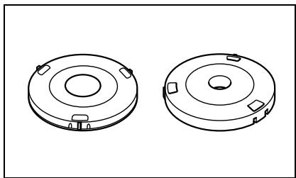
AC Adapter AC-A17
Used to supply power from an AC outlet to the instrument.
Input: Voltage 100 to 240 VAC (50-60 Hz)
Output: Voltage 5 VDC Current 2.8 A (Max.)
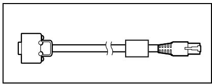
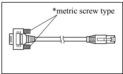
RS-232C Cable IF-A16
(for IBM PC/AT, 9-pin, 2 m)
Used to connect the instrument to a personal computer (PC).
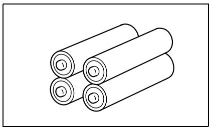
AA-size battery (× 4)
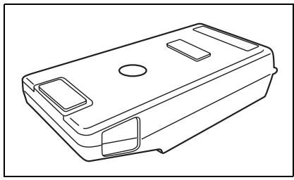
Zero Calibration Box (CM-A32)
Used to perform zero calibration.
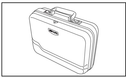
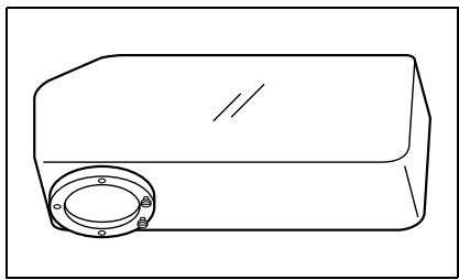
Hard Case (CM-A148)
Can be used for storing the CM-2600d/2500d, the instruction manual and standard accessories, such as the White Calibration Plate and AC adapter.

The Hard Case is designed purely for storing the above items and must not be used for transportation purposes.
Dust Cover Set (CM-A149)
Used when measuring powder or wet surfaces.
It can also be used when woven fabric needs to be laid flat and measured.

The Dust Cover (CM-A152) can be used as a vinyl cover for the replacement.
Color Data Software "SpectraMagic NX" (CM-S100w)
This software supports the two types of the target-mode, "linked to each data." and "defined in COND.", provided by this instrument. It allows you to operate the instrument from your PC, and to process data and manage files.
Printer Cable (CR-A75)
Used to transfer data to a printer. Connect a printer to the external output terminal on the instrument with this cable. The D-sub connector (9-pin) of the cable must be connected to the printer.
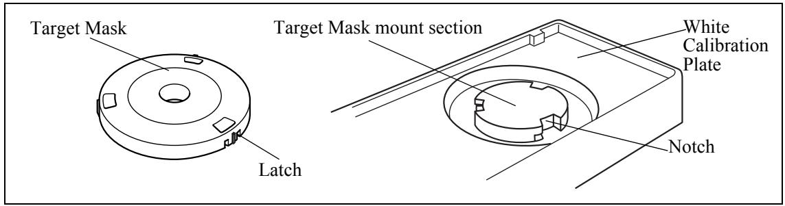
Names and Functions of Parts
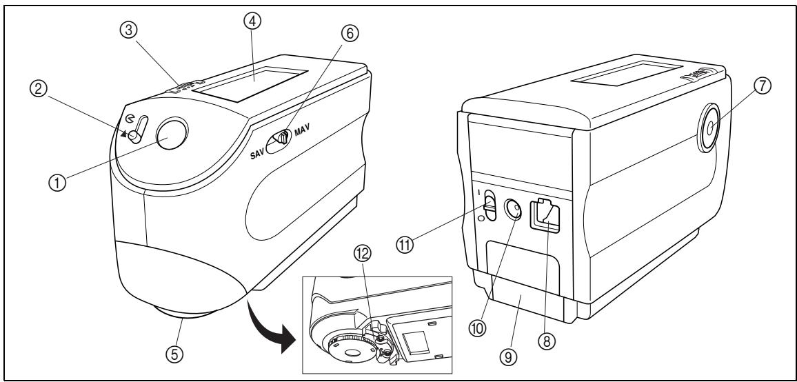
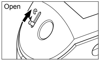
① Viewfinder
Used to check the position of the specimen. By sliding the lever you can check whether the specimen is set correctly.
② Viewfinder lever
Used to open/close the viewfinder. By sliding the lever in the direction of the arrow, the white LED will light up and illuminate the specimen, so the specimen can be seen through the viewfinder to check that it is set correctly.
Memo
The specimen cannot be measured if the viewfinder is open and the white LED is lit.
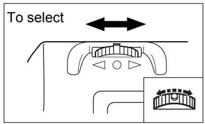
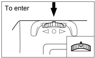
③ Navigation wheel
Use this navigation wheel to select an item or set the selected item.
To select an item, turn it to the right or left until the desired item is shown. To set the selected item, press it.
Memo No. 10
When selecting an item or setting a value, holding down the jog dial will switch the item or value from one to another continuously.
④ LCD display
Displays the setting items and measured data.
⑤ Specimen measuring port
A port provided to measure the specimen.
With the CM-2600d, a Target Mask must be attached to this port, according to the measurement area selector position.
⑥ Measurement area selector
Used to change the lens position according to the measurement area.
Memo
This switch is not available with the CM-2500d.
⑦ Measuring button (MEAS. button)
Press this button to perform calibration or measurement.
Memo No. 10
When setting measurement conditions or tolerances, this button can be used as UNDO button to return to the previous item.
External output terminal
To transfer data to an external device, connect the RS-232C cable (IF-A16) or printer cable (CR-A75) to this terminal.
⑨ Battery cover
A cover for the battery chamber. Four AA-size batteries must be set in the battery chamber in the correct polarity direction.
AC adapter terminal
When using the AC adapter (AC-A17), connect the adapter's plug to this terminal.
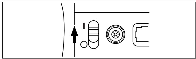
⑪ POWER switch
Used to turn ON/OFF power. Setting this switch to “ ” turns the power OFF, and setting it to “ | ” turns the power ON.
② Measuring Base
Use this base to attach the specimen securely to the instrument when analyzing small specimens.
White Calibration Plate CM-A145
(1) Cap
A cap provided to protect the White Calibration Plate.
Note
If you are not going to use the White Calibration Plate, attach the cap to the White Calibration Plate to prevent exposure to ambient light and protect it from scratches and dust.
② White Calibration Plate
Used to perform white calibration of the CM-2600d/2500d.
If you are not going to use it, attach the cap to prevent exposure to ambient light and protect it from scratches and dust.
③ Target Mask mount section
Used for storing a Target Mask that is not in use.
Memo No. 10
For attaching/removing a Target Mask, refer to "Attaching/Removing a Target Mask" (page E-14).
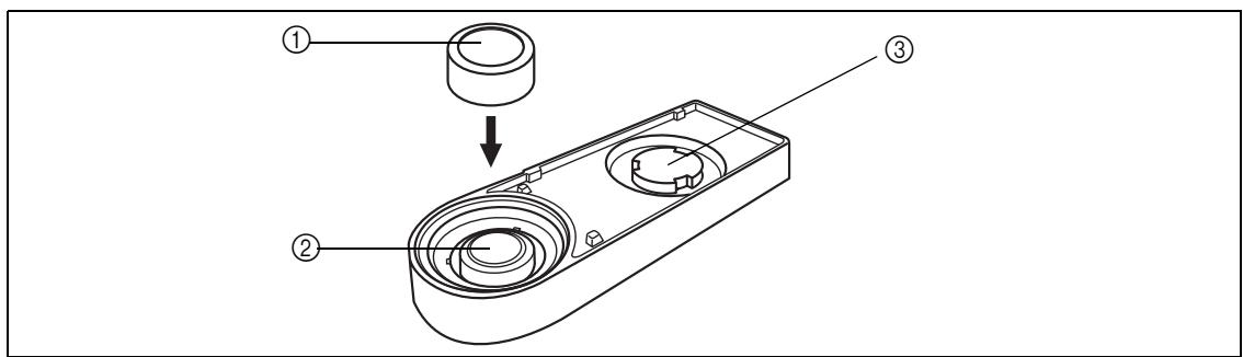
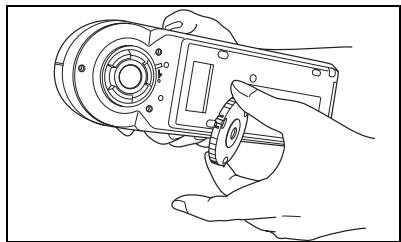
Attaching/Removing a Target Mask
With the CM-2600d, a Target Mask conforming to the selected lens position and measurement condition must be used. A Target Mask that is not in use can be attached to the Target Mask mount section of the White Calibration Plate, so that it can be stored together with the instrument.
To attach/remove a Target Mask, follow the procedure given below.
Memo
To facilitate attaching/removing a Target Mask, turn the instrument over so that the specimen measuring port is face up.
Note
- When attaching/removing a Target Mask, take care not to allow dirt and dust to enter the integrating sphere though the measuring port.
- Do not exert excessive force on the latch of the Target Mask. Doing so may damage the latch, disabling use of the Target Mask.
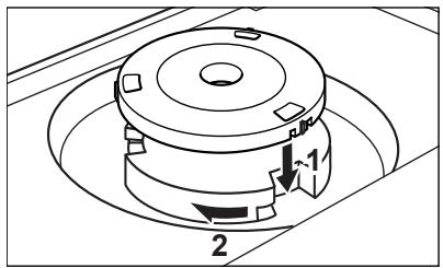
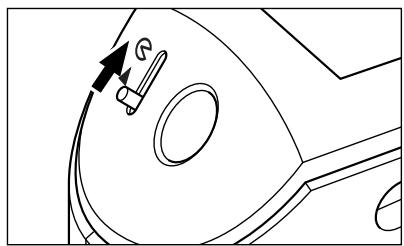
Attaching/Removing a Target Mask to/from the Instrument
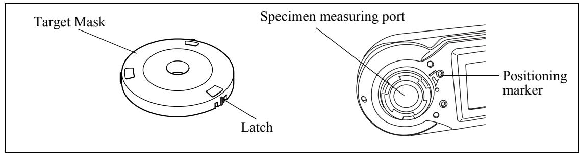
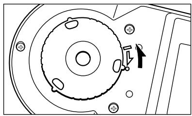
Attaching a Target Mask
- Place the Target Mask on the specimen measuring port so that the marker on the latch is aligned with the “ ” marker on the port.
- Hold the outer edge of the mask, and turn it in the direction of the arrow (clockwise) until the marker on the latch is aligned with the "o" marker on the port.
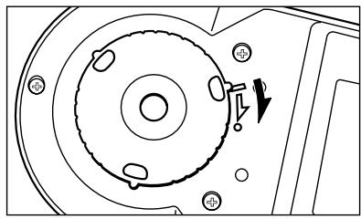
Removing the Target Mask
- Hold the outer edge of the mask, and turn it in the opposite direction to the arrow (counter-clockwise) until the marker on the latch is aligned with the " " marker.
- Hold the outer edge of the mask and remove it.
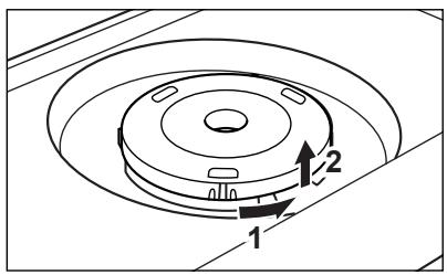
In the case of the CM-2600d, a Target Mask that is not in use can be attached to the Target Mask mount section of the White Calibration Plate, so that it can be stored together with the instrument.
Memo
Even in the case of the CM-2500d, when the Target Mask is removed for cleaning the integrating sphere, it can be attached to the Target Mask mount section of the White Calibration Plate to prevent loss and damage.
Note
- Do not touch the inner surface of the Target Mask or allow it to get dirty and scratched.
- Do not exert excessive force on the latch of the Target Mask. Doing so may damage the latch, disabling use of the Target Mask.
Attaching a Target Mask
- Place the Target Mask on the Target Mask mount section so that the inner surface of the latch is aligned with the notch on the White Calibration Plate.
- Hold the outer edge of the mask and turn it clockwise to secure it.
Removing the Target Mask
- Hold the outer edge of the mask and turn it counter-clockwise until the inner surface of the latch is aligned with the notch on the White Calibration Plate.
- Hold the outer edge of the mask and remove it.
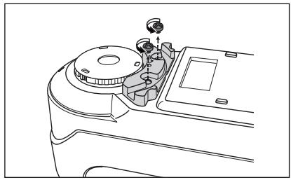
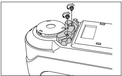
Attaching/Removing the "Measuring Base"
A "Measuring Base" has been included with the Spectrophotometer CM-2600d/2500d.
This allows small specimens to be attached securely to the instrument when they are being measured, and this enables more accurate measurements to be made.
The "Measuring Base" is shown in the illustration to the right, and is attached to the base of the CM-2600d/2500d with two screws.
Note
- Make sure that the "Measuring Base" is securely attached to the instrument before calibrating the instrument or taking measurements.
- You must remove the "Measuring Base" before using the optional Zero Calibration Box or Dust Cover Set.
- When removing the "Measuring Base", make sure that the screws used to attach the base to the instrument are stored properly and are not misplaced.
If the screws do become mislaid, replace them with screws that meet the specifications shown to the right.
[Screw name]
Cross-Recessed Pan Head Machine Screw M3, Nominal Length 4-5 mm

Measuring Base
"Measuring Base" attachment hole
Specifications for "Measuring Base" attachment screws Diameter of screw head (head diameter): 5 - 6.5mm
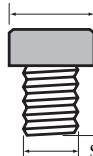
Thickness of screw head (head height): less than 3mm
Length of screw body (body length): 4-5 mm
Terms in parenthesis () are JIS defined terms for parts of screws
Attaching/Removing the "Measuring Base" to/from the Instrument
Removing the "Measuring Base"
- Place the CM-2600d/2500d so that its base is facing up and it is stable.
- Using a crosshead screwdriver, turn the two attachment screws counterclockwise and remove them.
Use a crosshead screwdriver that is a suitable size for the screws.
Attaching the "Measuring Base"
- Place the CM-2600d/2500d so that its base is facing up and it is stable.
- Place the "Measuring Base" on the base of the CM-2600d/2500d as shown in the illustration.
Place the "Measuring Base" so that it is aligned with the attachment holes in the base of the CM-2600d/2500d. When placing the "Measuring Base" on the base of the CM-2600d/2500d, make sure that nothing is trapped between the instrument and the base.
- Using a crosshead screwdriver, turn the two attachment screws clockwise and tighten them securely.
Do not tighten the screws too tightly.
Cleaning Each Part
This section explains how to clean the White Calibration Plate, Target Mask and inside of the integrating sphere.
White Calibration Plate
Gently wipe off dirt with a soft dry cloth. If dirt is difficult to remove, dampen a cloth with commercially available lens cleaning liquid and wipe. Then remove the liquid with a cloth dampened with water, and leave it to dry.
Note
Take care not to scratch the White Calibration Plate.
Target Mask
Use a blower to remove dirt and dust from the Target Masks.
Note
Do not touch the inner surface of the Target Masks with your fingers or wipe them with a cloth. If the Target Masks are so dirty that dirt cannot be removed with a blower, contact the nearest KONICA MINOLTA SENSING-authorized service facility.
Inside the Integrating Sphere
Memo
For attaching/removing a Target Mask, refer to "Attaching/Removing a Target Mask" (page E-14).
- To prevent dust and dirt entering the optics section from the integrating sphere, slide the viewfinder lever to open the viewfinder.
- Remove the Target Mask.
- Use a blower to remove dirt and dust from the integrating sphere.
Note
Do not touch the white-coated inner surface of the integrating sphere, wipe it with a cloth or put any object inside it. If the surface is so dirty that dirt cannot be removed with a blower, contact the nearest KONICA MINOLTA SENSING-authorized service facility.
Inserting the Batteries
To supply power to the instrument, the AC adapter (AC-A17) or four AA-size batteries (Alkaline or NiMH battery is recommended for better service life) must be used. Use either the AC adapter or batteries, according to which suits your application.
Note
- If you are not going to use the instrument for more than two weeks, make sure that the batteries are removed. If the batteries are left in the instrument for long periods of time, battery electrolyte may leak and damage the instrument.
- Do not use batteries of different types or mix new batteries with old ones. Doing so may result in battery explosion or reduction of battery life.
- Do not touch or short-circuit the terminals inside the battery chamber. Doing so may result in breakdown of the instrument.
[Operating Procedure]
1 Make sure that power is OFF (i.e. the POWER switch is set to "O").
![KONICA CM-2600D - [Operating Procedure] - 1](/content/2025/01/172133/images/19ee67fd73c41473311a8d5c65e3876a3dde586d5aec7c3c8113ce2952c1e778.jpg)
2 Slide the battery cover on the rear of the instrument to open it.
![KONICA CM-2600D - [Operating Procedure] - 2](/content/2025/01/172133/images/0f5bfd9d8db72abdb48d52c12bd7804b72b51c7e1dcf3d6623f9631170a7ca44.jpg)
3 Place four AA-size batteries in the battery chamber. Make sure that the batteries are placed in the correct direction.
![KONICA CM-2600D - [Operating Procedure] - 3](/content/2025/01/172133/images/d5d3ff5b2f28344c428ff5fc19a517a51e32a15c6c09d7b008e43b6da622999c.jpg)
4 Align the marker on the battery cover with that on the instrument, and slide the battery cover to close it.
![KONICA CM-2600D - [Operating Procedure] - 4](/content/2025/01/172133/images/f376078495a81d5d66b12b9c4a63124ba1bf7d8ad7d8d7ee19f4202b44a1f10b.jpg)
Connecting the AC Adapter
Memo
Use of the AC adapter (AC-A17) rather than batteries is recommended, since more power will be required when the external output terminal is used to output data to an external device or print it.
Note
- To supply AC power to the instrument, always use the AC adapter (AC-A17) supplied with the instrument.(Rated: 5 V, 2.8 A)
- Before connecting or removing the AC adapter, make sure that power is turned OFF.
[Operating Procedure]
1 Make sure that power is OFF (i.e. the power switch is set to "O").
![KONICA CM-2600D - [Operating Procedure] - 1](/content/2025/01/172133/images/6e2fbfed0d2f6bc6abe271a03c0987c278ccb69f2c86ed0c7cce058eff351e77.jpg)
2 Connect the AC adapter's connector plug to the AC adapter terminal on the rear of the instrument.
![KONICA CM-2600D - [Operating Procedure] - 2](/content/2025/01/172133/images/60310a073ba4331d3785af14f788e242eb56072e2212f8794f950b2928e3d630.jpg)
3 Insert the AC adapter's power plug to an AC outlet (100-240 VAC, 50-60 Hz).
![KONICA CM-2600D - [Operating Procedure] - 3](/content/2025/01/172133/images/da126825bc22c466fe3f34a0b4b42e7d5c963fc9c7bff7fcd8489a67faf29205.jpg)
![KONICA CM-2600D - [Operating Procedure] - 4](/content/2025/01/172133/images/e0b67b59cd01098f519a86e2557cefa48e41deb4dd203d0e07919937af48fef8.jpg)
When turning the power ON for the first time, the display language and measurement mode must be set.
For details, refer to page E-27.
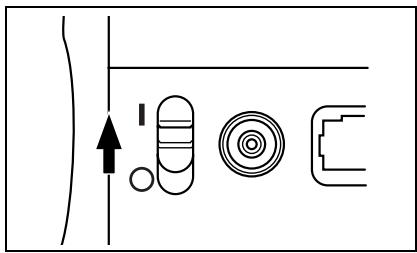
[Operating Procedure]
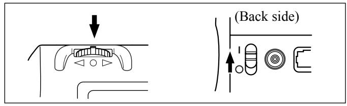
1 Set the POWER switch to "I".
The power will be turned ON.
Turning Power OFF
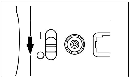
[Operating Procedure]
1 Set the POWER switch to “○”.
The power will be turned OFF.
Auto Power Save Function
Power save mode will be activated if the MEAS. button and navigation wheel are not operated for more than three minutes. During power save mode, the flash circuit will not be charged. To cancel power save mode, press the MEAS. button to start measurement.

- If the MEAS. button is pressed to cancel power save mode, start of measurement will be delayed by a few seconds, so keep the instrument still until the lamp flashes and measurement is taken.
- The auto power save function is not available in remote mode (see page E-89).
System Configuration
Language Mode
Contents on the LCD screen can be displayed in English, Japanese, German, French, Spanish or Italian. In this manual, explanation of operating methods and display is given for English mode.
Measurement Mode
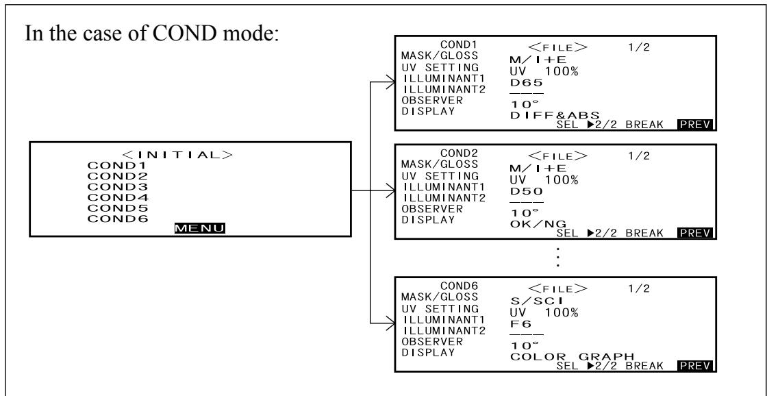
Two measurement modes (COND and TASK) are available with this instrument, and can be switched from one to another.
| Application |
| COND mode | Normal measurement mode. Measurement can be performed while the conditions are changed. In this mode, up to six sets of conditions (illuminant, observer angle, color space etc.) can be registered. |
| TASK mode | Special measurement mode. For continuous inspection, this mode allows you to perform measurement while messages indicating the measurement procedure are displayed on the LCD. The messages can be created by use of the previously used software SpectraMagic (Ver.3.2 or higher; except for Ver.3.5) with your PC. In this mode, color differences can be calculated one by one against up to 10 color difference target data.
■Note
·Before starting measurement, tasks (measurement procedure) must be down-loaded from the PC using SpectraMagic (Ver.3.2 or higher; except for Ver.3.5). TASK mode cannot be selected if no tasks have been downloaded.
·During TASK mode, only the data measured last is displayed. Use of SpectraMagic (Ver.3.2 or higher; except for Ver.3.5) allow you to access to previous data in the memory. |
Up to six sets of conditions can be registered either in COND or TASK mode.
Target Modes
- The CM-2600d/2500d supports two Target Modes, "defined in COND." mode and "linked to each data." mode, to analyze both measurement data and color difference. As with Language Mode and Measurement Mode, you can select the desired mode when you turn the power ON.
- The default setting is "linked to each data." mode. To switch to "defined in COND." mode or switch between the target modes, you need to follow the procedure to select target mode.
- Depending on the target mode selected, the display and the procedure for some operation for the instrument are different.
Below are some examples of these differences. (For details, see Target Mode in the Appendix.)
- In "linked to each data." mode, the next color difference data number is displayed next to the currently selected color difference data number in the initial settings screen.
When "defined in COND." mode is selected, it is not displayed.
- In "linked with each data" mode, to display the color difference for measurement data, you can only select the color difference for the currently selected measurement data. When "defined in COND." mode is selected, you can freely select the color difference data number after making measurements. You can also display the results of the selection.
- Data storage capacity for the "linked to each data." mode is 1700 pieces, and that for the "defined in COND." mode is 700 pieces.
Note
Once the target mode is changed, previous data will be cleared. It is recommended that you save previous data into other storage media in advance by using the Color Data Software that is optionally available.
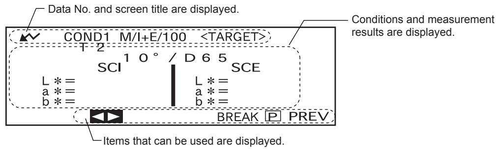
Screen Display
The basic screen structure is shown below.
Battery Alarm
When using CM-2600d/2500d with batteries, battery alarm indication appears when their power level lowers.
[Half battery indication]
If this indication (Half battery indication) appears, new batteries should be prepared for replacement in near future. Even with this indication displayed, measurements are still possible.
[Empty battery indication]
If this indication (Empty battery indication) appears, measurement or calibration is no longer possible. Replace batteries with new ones.
Data Saving
Data used with this instrument is saved automatically. Although white calibration data is retained in internal memory even after power is turned off, it is still necessary to repeat white calibration each time you switch the power back on.
Chapter 2
Preparation for Measurement

For the first time
For the second and subsequent times
Turning Power On for the First Time
When turning the power ON for the first time, the display language and measurement mode must be set.
Setting the Language Mode and Measurement Mode
Set the language and measurement mode as follows:
[Setting Procedure]
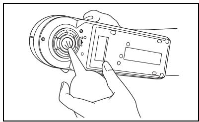
1 While pressing, turn the power ON.
The screen will appear, with the item "LANGUAGE" highlighted.

2 Turn to select the desired language, then press
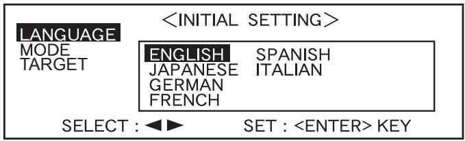
- When the cursor moves to the desired language, all the text will be displayed in the selected language.
3 Turn to select the desired measurement mode, then press
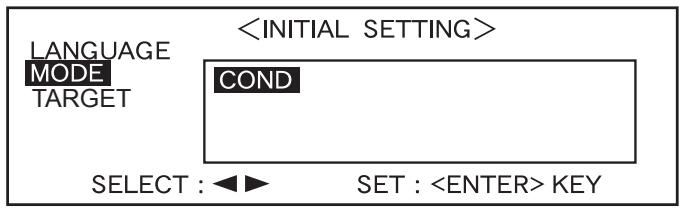
- If no tasks have been downloaded to the instrument, only "COND" will be displayed.
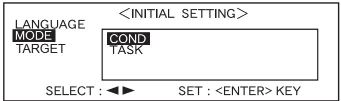
- If a task(s) has been downloaded to the instrument, both "COND" and "TASK" will be displayed.
- Select "COND".
Selecting the Target Mode
The default setting is "linked to each data." mode. The following procedure is required only if you want to switch the target mode.
Note
- If the Color Data Software "SpectraMagic CM-S9w" is used, switch the target mode to "defined in COND." mode.
- Once the target mode is changed, previous data will be cleared. It is recommended that you save previous data into other storage media in advance by using the Color Data Software that is optionally available.
[Setting Procedure]
1 Turn to select the desired target mode, then press
Memo
If you do not want to change the target mode, press
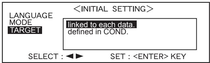
- The default setting is "linked to each data".
A warning message is displayed.
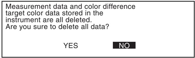
2 Turn to select "Yes", then press
The screen will appear.

Memo
If you select "No" and press OK, you will return to the screen shown in 1.
Initial Setting
The following five initial setting items are available.
(1) REMOTE.. Connects the instrument to the PC to enable bi-directional communications.
(2) AUTO PRINT............ If the instrument is connected to a printer, measured data will be printed automatically each time measurement is taken.
(3) CLOCK.... Adjusts the instrument's built-in clock.
(4) DISPLAY INVERT.... Reverses the display direction.
(5) LCD CONTRAST.... Adjusts the LED's contrast.
Memo
(1) REMOTE" and " (2) AUTO PRINT" can be used when connecting the instrument to a PC or printer.
The settings will be kept even if the power is turned OFF.
To make initial settings, follow the procedure given below:
[Setting Procedure]
1 Turn the power ON.

The

