
AC 9 FITP - Air conditioner ALPATEC - Free user manual and instructions
Find the device manual for free AC 9 FITP ALPATEC in PDF.
| Product type | Monoblock portable air conditioner |
| Brand | ALPATEC |
| Model | AC 9 FITP |
| Max cooling power | 2360 W |
| Cooling power | 2022 W |
| Max heating power | 2764 W |
| Power consumption (cooling) | 777 W |
| Power consumption (heating) | 1050 W |
| Dehumidification | 48 L/day |
| Max air flow | 270 m³/h |
| Fan speeds | 3 (Low, Medium, High) |
| Max hose length | 1.5 m |
| Hose diameter | 110 mm |
| Recommended area | Up to 16 m² |
| Compressor | Rotary |
| Refrigerant | R407C |
| Operating modes | Auto, Cooling, Heating, Fan, Dehumidification |
| Special functions | Built-in ionizer, Horizontal and vertical oscillation |
| Dust filter maintenance | Clean every 2 months with soapy water |
| Bio-filter maintenance | Replace at least once a year |
| Power supply | According to rating plate (220-240 V~) |
| Repairability | Repair only by an authorized professional |
Frequently Asked Questions - AC 9 FITP ALPATEC
User questions about AC 9 FITP ALPATEC
0 question about this device. Answer the ones you know or ask your own.
Ask a new question about this device
Download the instructions for your Air conditioner in PDF format for free! Find your manual AC 9 FITP - ALPATEC and take your electronic device back in hand. On this page are published all the documents necessary for the use of your device. AC 9 FITP by ALPATEC.
USER MANUAL AC 9 FITP ALPATEC
For your comfort and safety, ALPATEC has checked all the steps of manufacturing. The products have been made for you to enjoy their design and easiness to use. ALPATEC, a complete range of air conditioners, coolers, fans and heaters for you to be completely satisfied.
CAUTION
When using electrical appliances, some rules have to be respected. READ THESE INSTRUCTIONS CARREFULLY BEFORE USING THIS PRODUCT.
- Take care to install this product by complying with the national rules of electric installation. Make sure that the voltage on the rating plate is same as your main one before plugging. Always connect to earth ground.
- Place the appliance on a dry and level surface, with enough room, without obstacle. Clearance of 50 cm between product and wall is needed.
- Always place the appliance in a vertical position, in order to maintain the compressor in good working conditions.
- Never let the appliance in a room with children and handicapped people without supervising.
- Do not use outdoor, in a wet environment, close to a bath-tub, a shower or a swimming pool.
- Do not immerse appliance or power cord
- This product is provided with its own power cord. Do not use any other electrical connection but the one supplied and recommended by the manufacturer. This could be dangerous and may damage the appliance.
- Do not use if power cord or appliance is damaged
- Only use this appliance for domestic purpose, following the instructions of that manual.
- Never move or unplug by pulling the power cord.
- Unplug before cleaning or replacement of one part.
- Do not use without filter.
- In order to avoid any electrical interference, keep away from electric sources.
- Never use near a hot place.
- Do not use if it is not totally assembled and particularly if the protection grid is not secured, or the exhaust pipe is not assembled.
- Do not introduce parts through the grid.
- Do not put anything on the appliance. Do not block air inlet and outlet.
- Do not attempt to repair the appliance yourself. Otherwise, guarantee would cancel. It has to be repaired by a qualified worker. Power cord has to be changed by a qualified person if needed.
THE MANUFACTURER WILL NOT ASSUME ANY RESPONSABILITY IN CASE OF NON ADHERENCE TO THIS
RECOMMANDATIONS.
KEEP THIS MANUAL CAREFULLY.
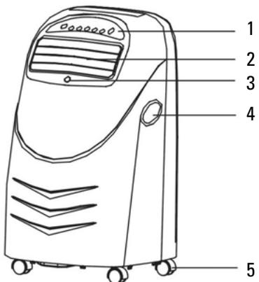
PARTS LIST
- Control panel
- Air outlet
- Remote control receptor
- Handle
- Casters
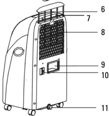
- Anti dust filter
- Bio-filtre
- Air inlet
-
Exhausted air outlet
-
Power cord
- Drainage knob
- Window adaptor
- Connection on product side (with clips)
- Wall accessory with cover
- Exhaust pipe with extremities
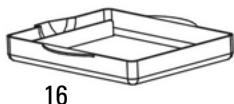
- Movable water tank
- Remote control
12
13
14
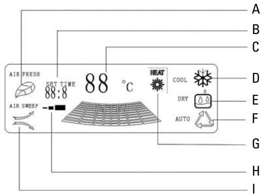
DISPLAY CONTROL
A. ionizeur
B. timer
C. temperature and error code
D. cooling
E. drying
F. automatic
G. heating
H. fan speed
I. air sweep
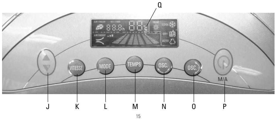
CONTROL PANEL
J. :adjust temperature or time
K. VITESSE : speed
L.MODE
M. TEMPS : timer
N.OSC left/right air sweep
0.OSC):up/down air sweep
P. M/A: on / off
Q.VFD screen
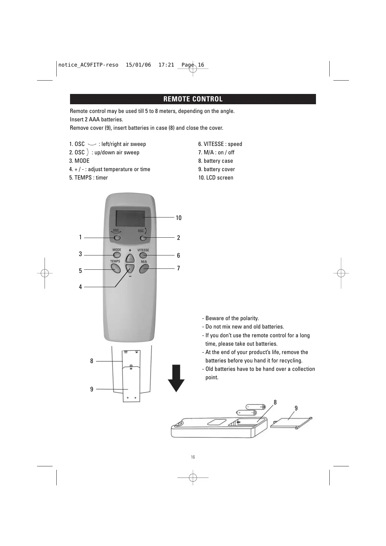
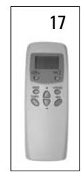
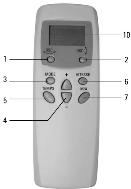
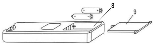
REMOTE CONTROL
Remote control may be used till 5 to 8 meters, depending on the angle.
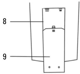
Insert 2 AAA batteries.
Remove cover (9), insert batteries in case (8) and close the cover.
1.OSC left/right air sweep
-
VITESSE : speed
-
OSC) : up/down air sweep
-
M/A: on / off
-
MODE
-
battery case
-
+ / - : adjust temperature or time
-
battery cover
-
TEMPS : timer
-
LCD screen

-Beware of the polarity.
- Do not mix new and old batteries.
- If you don't use the remote control for a long time, please take out batteries.
- At the end of your product's life, remove the batteries before you hand it for recycling.
- Old batteries have to be hand over a collection point.
Your product can be ran either with the control panel or with the remote control
In the following, only the control panel will be taken into account.
For the remote control please use the following correspondence:
| Touch on control panel | Corresponding touch on remote control |
| J | 4 |
| K | 6 |
| L | 3 |
| M | 5 |
| N | 1 |
| O | 2 |
| P | 7 |
On the LCD screen of remote control, indicators of each parameter will light on when needed.
STARTING:
Plug in the unit, a sound is heard
Press button M/A (P), the unit starts setting the last used parameters (mode, temperature and fan speed).
Room temperature is displayed on VFD screen.
SELECTION OF THE MODE:
Press button MODE (L) to change the mode.
Each time, function changes according to following diagram:
AUTOMATIC -> HEAT -> FAN ONLY -> COOLING -> DRY

ADJUSTMENT OF THE TEMPERATURE:
Use + / - (J) to set the temperature.
One pressure increases or decreases temperature by 1ircC .
Temperature is displayed on VFD screen.
A few seconds after, room temperature will be displayed again.
Temperature range is from 16ircC to 31ircC .
ADJUSTMENT OF THE FAN SPEED :
Each pressure, fan speed changes according to following diagram: LOW -> MEDIUM -> HIGH
DRY ONLY MODE.
During the dry operation, the fan speed cannot be adjusted. Low speed will be set automatically.
Adjustment of the temperature will have no effect.
FAN ONLY MODE.
It is no use adjusting temperature.
HEATING MODE.
There is an automatic regulation with a safety sensor.
When the sensor temperature is lower than 30ircC , high speed is selected. When it is higher than 45ircC , low speed is selected. If it is between the two values, the speed can be selected manually.
AUTOMATIC MODE.
Your unit will choose the mode to be run according to the room temperature:
If T ≤ 20ircC , heating mode.
If T > 24ircC , cooling mode.
Si 20ircC < T ≤ 24ircC , fan only mode.
STOP:
Press M/A (P).
A sound can be heard and the unit stops running.
TIMER:
To turn on the unit automatically, press TEMPS (M) when the unit is plugged but not running.
Set remaining time before starting using + / - (J) . Each pressure adds or removes half an hour, from 0.5 to 12h.
Remaining time before starting is displayed on VFD screen and adjusted every half hour.
Press TEMPS to cancel the timer.
To turn off the unit automatically, press TEMPS (M) when the unit is running.
Set remaining time before stopping using + / - (J). Each pressure adds or removes half an hour, from 0.5 to 12h.
Remaining time before stopping is displayed on VFD screen and adjusted every half hour.
Press TEMPS to cancel the timer.
ADJUSTMENT OF THE WIND DIRECTION.
The unit has an automatic oscillation in both directions.
Press OSC (N) and OSC (O) to start or stop oscillations.
Corresponding indicator switch on or of on VFD screen.
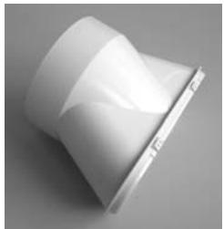
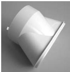
AIR EXHAUST PIPE.
Assemble extremity 13 on the pipe.
Assemble the pipe on the air conditioner in the exhaust air outlet 7.
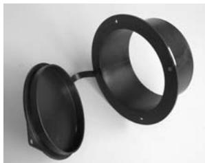
- Through a wall:
Make a hole in the wall with diameter adapted to part 14.
Insert part 14 in the hole and extremity of the exhaust pipe in part 14.
If you do not use the air conditioner, you can close the hole using the cover of part 14.
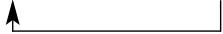
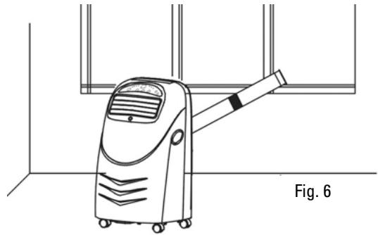
- Through the window or the door:
Assemble window accessory 12 on the exhaust pipe extremity.
Open door or window and put the extremity of the pipe through it. (Fig. 6 and 6bis)
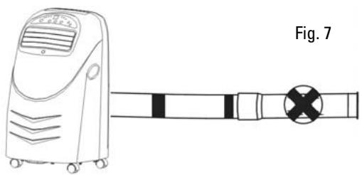
Note :
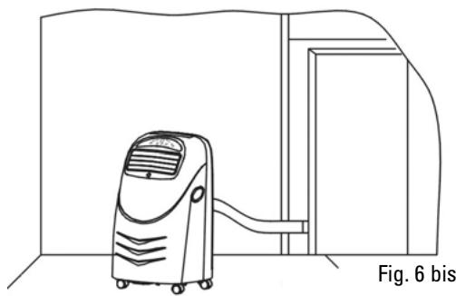
- Exhaust pipe can be as 1m50 long. The shorter it is, the more powerful your unit will be. Do not use additional exhaust pipe. (Fig. 7)
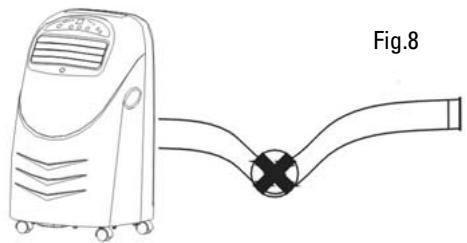
- The pipe must not be damaged or bent. (Fig. 8)
DRAINING OPERATION.
Your product is with shower technology, that means that most of the moistures will be drained through the exhaust pipe.
This is automatic.
Sometimes there are too many moistures and some parts go in an inner water tank.
When the water tank is full, E2 error appears on VFD screen, unit "bip" several times and stops working.
Turn off the unit, put the movable water tank (16) under the drainage knob (11) and unscrew the knob and rubber plug to let water flow out.
When water tank is empty, replace knob and rubber plug and restart the unit.
CLEANING
Before any cleaning operation, stop and unplug the unit.
Do not use chemical solvent.
Use a dry and wet cloth to clean the outside of the unit.
Anti dust air filter:
If the anti dust air filter is dirty, the air conditioner will be less performing.
Clean the filter at least every two months.
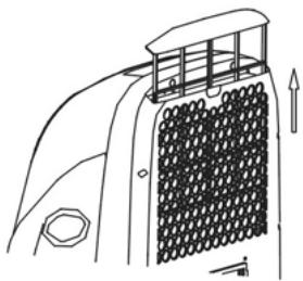
Take the filter (6) upward.
Take out the Bio-filter (7).
Wash with warm water and neutral cleanser, dry.
Put back the Bio-filter and the anti dust filter.
Bio-filter:
This filter is a non-washable filter: if Bio-filter becomes dark, change it. At least, replace the filter once a year.
TROUBLE SHOOTING.
Before asking for repair service, please check:
| Problems | Causes | Suggest solution |
| Unit does not work | - It is not plugged in - Socket or plug is damaged - Fuse or power cord are damaged | - Plug in - Change it - Make it repair by a qualified person |
| Unit stops working automatically | - Timer was on | - Cancel timer |
| No cool in cooling mode | - Room temperature is lower than set temperature - Evaporator is frosted | - Normal symptom - Eliminate frost |
| No heat wind in the heating mode | - Room temperature is higher than set temperature - Condenser is frosted - The unit is pre-heating | Normal symptom Eliminate frost Normal symptom: after pre-heating, unit will start working |
| VFD screen display E3.E4.E5 | The coil pipe is damaged | Change the coil pipe |
| VFD screen display E2 | Water tank is full | Empty water tank |
| VFD screen display E1 | - Voltage is too high or too low - Unit is damaged | Restart when voltage is normal Make it repair by a qualified person |
When there is something wrong with your unit, contact a qualified person.
TECHNICAL SPECIFICATIONS
| Rotative compressor | R 407 C |
| Max cooling capacity | 2360 W |
| Cooling capacity | 2022 W |
| Max heating capacity | 2764 W |
| Power input (cool / heat) | 777W / 1050 W |
| Deshumidifying capacity | 48 L / jour |
| Air flow (max) | 270 m / h |
| Fan speed | 3 |
| Exhaust pipe length | 1.5 m |
| Exhaust pipe diameter | 110 mm |
| Suitable for rooms up to | 16 m² |
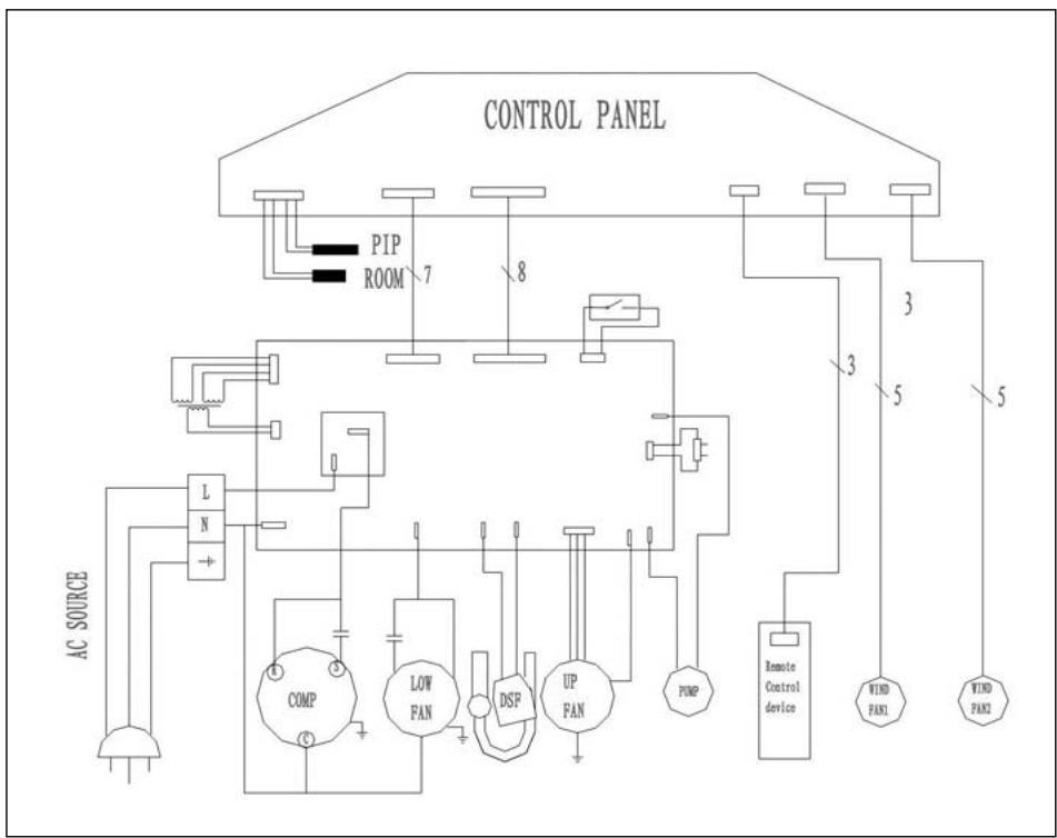
ELECTRIC DIAGRAM

Instructions on environment protection
Do not dispose of this product in the usual household garbage at the end of its life cycle; hand it over a collection point for the recycling of electrical and electronic appliances. The symbol on the product, the instructions for use or the packing will inform about the methods of disposal. The materials are recyclable as mentioned in its marking. By recycling or others forms of re-utilization of old appliances, you are making an important contribution to protect our environment. Please inquire at the community administration for the authorized disposal location.
ALPATEC
SOLUTIONS CLIMATIQUES
12/05
- CAUTION
- PARTS LIST
- DISPLAY CONTROL
- CONTROL PANEL
- REMOTE CONTROL
- STARTING:
- SELECTION OF THE MODE:
- ADJUSTMENT OF THE TEMPERATURE:
- ADJUSTMENT OF THE FAN SPEED :
- DRY ONLY MODE.
- FAN ONLY MODE.
- HEATING MODE.
- AUTOMATIC MODE.
- STOP:
- TIMER:
- ADJUSTMENT OF THE WIND DIRECTION.
- AIR EXHAUST PIPE.
- Note :
- DRAINING OPERATION.
- CLEANING
- Anti dust air filter:
- Bio-filter:
- TROUBLE SHOOTING.
- Instructions on environment protection
- ALPATEC
- SOLUTIONS CLIMATIQUES
Brand : ALPATEC
Model : AC 9 FITP
Category : Air conditioner