
PROBASS 500 - Bass Amplifier PEAVEY - Free user manual and instructions
Find the device manual for free PROBASS 500 PEAVEY in PDF.

| Product Type | Bass Amplifier |
| Brand | PEAVEY |
| Model | PROBASS 500 |
| Form Factor | 2U rack (compact) |
| Output Power | 500 W @ 2 Ω, 350 W @ 4 Ω, 200 W @ 8 Ω |
| Preamp | 12AX7 Tube |
| Power Stage | Transistor |
| Instrument Inputs | 1/4" Jack (front and rear), with -10 dB pad for active basses |
| Outputs | 1/4" Jack (speakers), Speakon, balanced XLR line output, preamp output, tuner output (1/4" Jack) |
| Equalization | Bass and treble shelving (+/-15 dB at 30 Hz and 10 kHz), 3-band parametric EQ (frequency, Q width, boost/cut) |
| Effects Loop | Series with mix pot (Dry/Wet), footswitchable |
| Additional Features | Mute mode, Contour (simulates tube power stage), low-cut filter, DDT™ speaker protection, ground lift, pre/post EQ for line output |
| Power Supply | 120 VAC, 60 Hz, 600 W |
| Maintenance and Cleaning | Do not block air intakes. Clean with a dry cloth. Have repairs carried out by a certified Peavey technician. |
| Safety | Do not open (risk of electric shock). Use a grounded power cord. Do not expose to rain or moisture. |
| Spare Parts and Repairability | Repair by a certified Peavey repairer only. Resettable fuse via reset switch. |
| Optional Footswitch | Controls effects loop and mute mode (stereo Jack) |
Frequently Asked Questions - PROBASS 500 PEAVEY
User questions about PROBASS 500 PEAVEY
0 question about this device. Answer the ones you know or ask your own.
Ask a new question about this device
Download the instructions for your Bass Amplifier in PDF format for free! Find your manual PROBASS 500 - PEAVEY and take your electronic device back in hand. On this page are published all the documents necessary for the use of your device. PROBASS 500 by PEAVEY.
USER MANUAL PROBASS 500 PEAVEY
PROBASS 500 Operation Manual

Intended to alert the user to the presence of uninsulated "dangerous voltage" within the product's enclosure that may be of sufficient magnitude to constitute a risk of electric shock to persons.

Intended to alert the user of the presence of important operating and maintenance (servicing) instructions in the literature accompanying the product.
CAUTION: Risk of electrical shock — DO NOT OPEN!
CAUTION: To reduce the risk of electric shock, do not remove cover. No user serviceable parts inside.
Refer servicing to qualified service personnel.
WARNING: To prevent electrical shock or fire hazard, do not expose this appliance to rain or moisture. Before using this appliance, read the operating guide for further warnings.

WARNING: When using electrical products, basic cautions should always be followed, including the following:
- Read these instructions.
- Keep these instructions.
- Heed all warnings.
- Follow all instructions.
- Do not use this apparatus near water.
- Clean only with a dry cloth.
- Do not block any of the ventilation openings. Install in accordance with manufacturer's instructions.
- Do not install near any heat sources such as radiators, heat registers, stoves or other apparatus (including amplifiers) that produce heat.
- Do not defeat the safety purpose of the polarized or grounding-type plug. A polarized plug has two blades with one wider than the other. A grounding type plug has two blades and a third grounding plug. The wide blade or third prong is provided for your safety. If the provided plug does not fit into your outlet, consult an electrician for replacement of the obsolete outlet.
- Protect the power cord from being walked on or pinched, particularly at plugs, convenience receptacles, and the point they exit from the apparatus.
- Only use attachments/accessories provided by the manufacturer.
- Use only with a cart, stand, tripod, bracket, or table specified by the manufacturer, or sold with the apparatus. When a cart is used, use caution when moving the cart/apparatus combination to avoid injury from tip-over.
- Unplug this apparatus during lightning storms or when unused for long periods of time.
- Refer all servicing to qualified service personnel. Servicing is required when the apparatus has been damaged in any way, such as power-supply cord or plug is damaged, liquid has been spilled or objects have fallen into the apparatus, the apparatus has been exposed to rain or moisture, does not operate normally, or has been dropped.
- Never break off the ground pin. Write for our free booklet "Shock Hazard and Grounding." Connect only to a power supply of the type marked on the unit adjacent to the power supply cord.
- If this product is to be mounted in an equipment rack, rear support should be provided.
- Exposure to extremely high noise levels may cause a permanent hearing loss. Individuals vary considerably in susceptibility to noise-induced hearing loss, but nearly everyone will lose some hearing if exposed to sufficiently intense noise for a sufficient time. The U.S. Government's Occupational and Health Administration (OSHA) has specified the following permissible noise level exposures:
| Duration Per Day In Hours | Sound Level dBA, Slow Response |
| 8 | 90 |
| 6 | 92 |
| 4 | 95 |
| 3 | 97 |
| 2 | 100 |
| 1 1/2 | 102 |
| 1 | 105 |
| /2 | 110 |
| 1/4 or less | 115 |
According to OSHA, any exposure in excess of the above permissible limits could result in some hearing loss. Ear plugs or protectors to the ear canals or over the ears must be worn when operating this amplification system in order to prevent a permanent hearing loss, if exposure is in excess of the limits as set forth above. To ensure against potentially dangerous exposure to high sound pressure levels, it is recommended that all persons exposed to equipment capable of producing high sound pressure levels such as this amplification system be protected by hearing protectors while this unit is in operation.
SAVE THESE INSTRUCTIONS!
ENGLISH
PROBASS 500
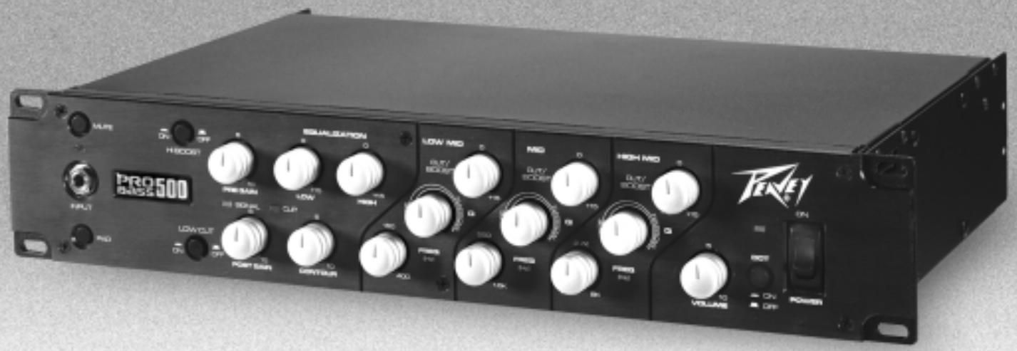
Congratulations on your purchase of the PROBASS 500 by Peavey. You'll find features and tone galore in this 2-rack space bass amplifier. The PROBASS 500 offers a tube front-end (preamp) section for that smooth tube sound combined with a solid-state amplifier for mind-blowing power. The PROBASS 500 is a professional bass amp with flexible features not even found on the high-end boutique power amps. This amp includes a -10 dB pad switch for your active basses; a tuner send with an input mute for silent tuning; both active EQ and full parametric EQ; front and rear 1/4 inputs; a 3-position ground lift switch for those troublesome situations; a side chain effects loop with wet/dry control and much more. Combine these features with Peavey's long-standing reputation for reliability and you can't go wrong!
Please read this guide carefully to ensure your personal safety as well as the safety of your equipment.
Features
12AX7 preamp tube for warm tube sound
500 Watts @ 2 Ohms; 350 Watts @ 4 Ohms; 200 Watts @ 8 Ohms
front and rear 1 / 4'' input jacks
-10 dB pad for active basses
tuner send jack for easy tuner hookup
input mute with blinking LED for silent tuning
contour control for tube-type EQ curve
active low and high shelving-type EQ
3-bands of versatile, full-parametric equalization
side chain effects loop with wet/dry control
foot switch capable input mute and effects loop
low Z electronically balanced line out with pre/post EQ switch
ground lift switch for line out
both Speakon® and 1/4" speaker jacks
preamp out/power amp in jacks
DDT speaker protection system with defeat switch
2-rack space unit
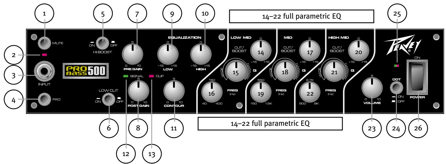
1 mute switch
When this switch is depressed the input is muted for silent tuning or break time!
2 mute status LED
When the mute switch is enabled the red mute status LED blinks.
3 input jack
This mono 1 / 4'' input will accept signals from all types of bass pickups. This input, when utilized, overrides the rear 1 / 4'' input jack.
4 input pad switch
Provided for instruments that have extremely high output (i.e. active pickup systems), which can result in overdriving (distorting) the input gain stage. Depressing the switch reduces the level of input by 10 dB.
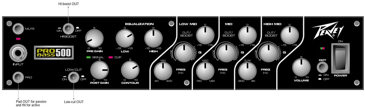
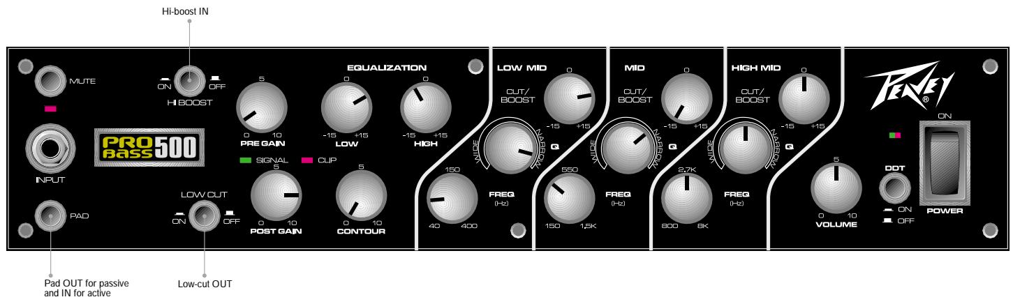
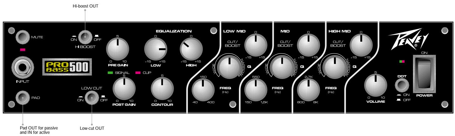
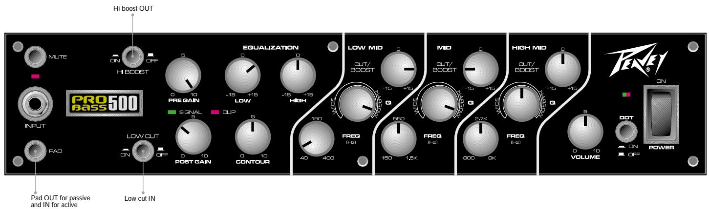
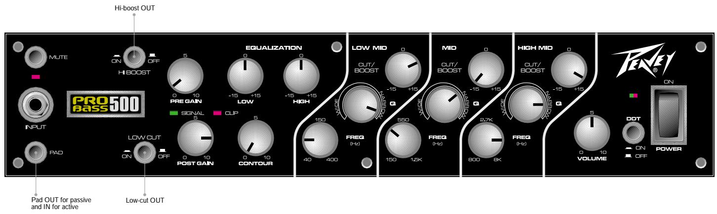
5 hi boost switch
Adds high frequency boost equalization. Notice that the high frequency boost becomes less effective with more preamp gain.
6 low cut switch
Used to reduce the amount of low frequency throughout the system for smoother tube distortion sounds.
7 pre gain
Controls the input gain of the tube stages.
8 post gain
Controls the volume level of the tube stages. If the clip indicator lights, the post gain should be reduced.
9 low
An active tone control (shelving type, + / - 15 dB @ 30 Hz) that varies the low frequency boost or cut.
10 high
An active tone control (shelving type, +/-15 dB @ 10 kHz) that varies the high frequency boost or cut.
11contour control
Provides a specially voiced EQ as the knob is rotated clockwise. When the knob is fully counterclockwise (set to o), there is no voicing added. (This control is similar to the old passive tube EQs with the lows and highs up and the mid down.)
12 signal status LED (green)
Illuminates when a signal is present.
13 signal clip indicator (red)
This LED indicates (when lit) that the preamp and tone circuits are being clipped (distorted). Reducing the post gain until the clip LED no longer lights will alleviate this problem.
14-22 3-band parametric EQ
Each band of the parametric EQ section has a control for: cut/boost; bandwidth (Q) and frequency. This is a full parametric EQ! All three bands of parametric EQ overlap, giving you control over the entire tonal spectrum.
14, 17, 20 cut/boost
This control behaves like any other active EQ control where CW (clockwise) rotation provides boost, CCW (counterclockwise) rotation provides cut and the 12 o'clock position (detent) provides no action at all (no cut or boost).
15, 18, 21 bandwidth (Q)
The bandwidth controls determine how wide or narrow a range of tones will be affected by the cut/boost control. For instance, when the bandwidth control is fully CCW, the cut/boost control will affect a wide range of frequencies (wide bandwidth = low Q). When the bandwidth is fully CW, the cut/boost will affect a very narrow range of tones (narrow bandwidth = high Q). If the bandwidth control is somewhere between the two extremes, the bandwidth will likewise be somewhere between wide and narrow. As the control is rotated CW, the bandwidth gets narrow. As the control is rotated CCW, the bandwidth gets wide. A good place to start is with the bandwidth set to the 3 o'clock position. This is roughly where many "semi-parametric" EQs are set.
16, 19, 22 frequency
The frequency controls determine the center point at which the cut/boost will take action. Think of the bandwidth control affecting the range of tones being acted upon and the frequency control determining the center point of those tones.
Note about frequencies:
The electric bass generates notes with frequencies ranging from about 30.9Hz (low B-string on a five-string bass) to about 523.3Hz (high C-string on a six-string bass). It may help you to think of frequencies as notes on your instrument or notes that you sing. By doing this, the concept of bandwidth and frequency becomes easier to understand. The bandwidth control determines the number of notes being affected and the frequency control determines the center of that range of notes.
Below are a few more pitches with their corresponding frequencies:
Four-string bass:
E string = 41.2Hz
A string = 55.0 Hz
D string = 73.4Hz
G string = 98.0Hz
23 master volume
This knob controls the overall volume level of the system.
24 DDT™ enable/disable switch
DDT speaker protection is disabled when the button is depressed or in the "in" position. DDT should be enabled at all times to protect your speakers.
25 power LED/DDT indicator
The LED is green when the power switch is in the "on" position. During normal operation, this LED also acts as a DDT/clip indicator. The LED illuminates red when DDT speaker protection is taking place or when the power amp is clipping (if DDT is disabled).
26 power switch
Used to turn AC mains power on or off.
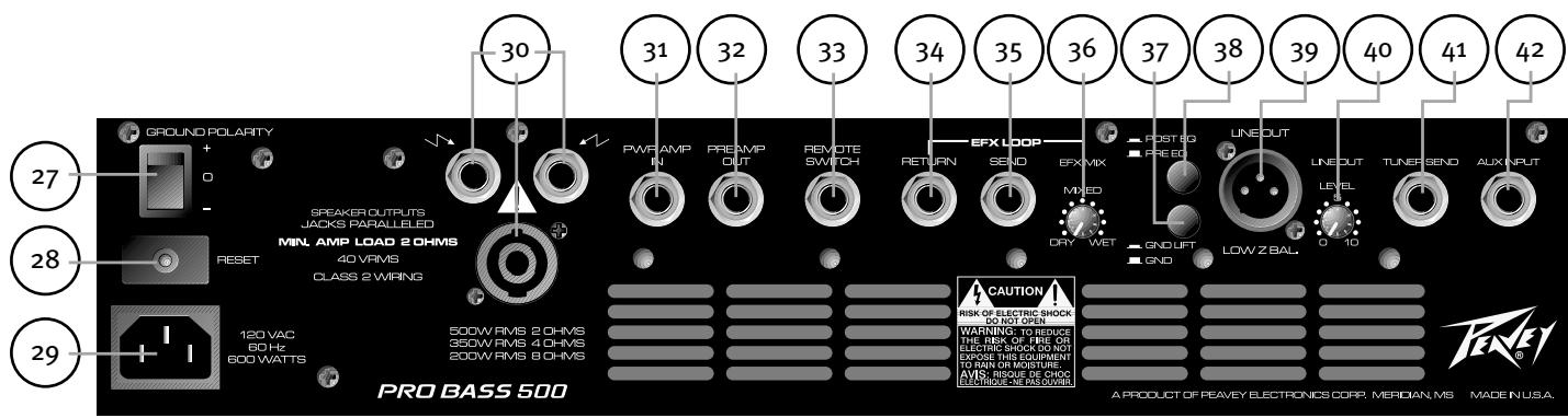

27 ground polarity switch
The ground switch is a 3-position, rocker-type switch. Under normal operation it should be in the center (zero) position. If hum or noise is present with the ground switch in the center position, place the ground polarity switch to positive or negative (+ or -) to minimize hum. Should a problem continue, consult your authorized Peavey dealer, the Peavey factory or a qualified service technician. Note: The ground switch is not functional on 220/240 Volt models.
28 reset/circuit breaker switch
Use this switch to restore power to the unit when the internal breaker is tripped. Turn the power switch to the off position before resetting the breaker. To reset, push the reset button in and release it. Turn the unit back on and confirm that the power LED is on. If the breaker is tripped again upon power-up, consult your authorized Peavey dealer, the Peavey factory or a qualified service technician.

29 IEC connector/detachable line cord
For your safety, we have incorporated a detachable, 3-wire line (mains) cord with proper grounding facilities. It is not advisable to remove the ground pin under any circumstances. If it is necessary to use the amp without proper grounding facilities, a suitable grounding adapter should be used. Refer to the back of your amp for the proper voltage requirements before connecting to a power receptacle.

30 speaker output jacks
There are two 1/4 '' jacks and one Neutrik type jack that provide the powered signal from the amplifier. Each connector is electrically the same (parallel). Use one of the jacks to connect your speaker cabinet and the other to add a second speaker cabinet in parallel. The minimum speaker load impedance is 2 Ohms or two 4 Ohm speakers in parallel.
Warning: To prevent the amplifier from overheating, the front and rear fan vents should remain clear of obstructions.
31 power amp input
Used to connect a line level signal to the power amplifier (i.e. external preamp). This jack, when used, disconnects the internal preamp.
32 preamp out
The preamp output can be used to route the amplified signal to a mixing console, tape recorder or other device. Connect the preamp output using a shielded cable to an input of one of these devices. This does not affect the operation of the amplifier. The preamp out and power amp in jacks can also be used as a line level effects patch point.
33 remote jack switch
Provided for an optional footswitch. Allows remote selection of the input mute and the effects loop. Mute switch on front panel must be depressed to the IN position for the footswitch to function properly.
34 effects return
Input for returning signals from an external low-level effects device or signal processing unit.
35 effects send
Output for supplying signal to an external low-level effects or signal processing unit.
36 effects mix
Since the effects loop on the ProBass 500 is a side-chain effects loop, the mix between the dry (unaffected) and wet (effects) signal can be adjusted with this control. When the control is fully CCW, there will be no effects present (dry). When the control is fully CW, the effects loop is fully wet. This same mix is set to the post EQ XLR as well as the main preamp out.
37 line out ground lift switch
Provides ground to be made from the line out jack or lifted to eliminate ground loops from the ProBass 500 and external source(s). There may be some rooms or situations when audible hum and/or noise is present. Minimizing this noise may be possible by depressing this switch.
38 select switch
Allows selection of a pre EQ or post EQ send to the low Z balanced line out jack. The "out" position selects pre EQ and the "in" position selects post EQ line out.
39 line out (low Z balanced)
An XLR jack is provided to route the signal to a mixing console or recording equipment. This output can be selected for pre EQ or post EQ operation.
4o line out level control
Controls the output level of the balanced line level output.
41 tunesendjack
This 1 / 4'' jack is provided for connecting an instrument tuner to your amp. Its signal is buffered off the input jack so it is just like plugging directly into the tuner.
42 auxiliary input jack
This 1/4 " jack is provided for connecting an instrument to the amp from behind the rack. It is just like plugging directly into the front panel input jack. Note that the front panel input jack overrides the rear panel input jack. This means that if you are using the rear panel input jack and then plug another instrument into the front panel, the rear panel input will be defeated.
PROBASS 500™
SPECIFICATIONS
SYSTEM SPECIFICATIONS
Mains Circuit Breaker:
5 amps
Mains Voltage:
120 VAC 60 Hz
Power Consumption:
600 Watts
Hum and Noise:
Typically greater than -80 dB unweighted.
With controls set as follows:
Pad = passive
Bright = Normal (out)
Low Cut = Normal (out)
Pre Gain = 9 o'clock (roughly 2)
Post Gain = 10
Contour = 0
Low = 0
High = 0
Parametric Band 1: cut/boost = 0;
bandwidth = 0; frequency = 0
Parametric Band 2: cut/boost = 0;
bandwidth = 0 ; frequency = 0
Parametric Band 3: cut/boost = 0;
bandwidth = 0 ; frequency = 0
Master Volume = 5
POWER AMPLIFIER SECTION
Protection:
Electronic current limit protection circuit
Thermal protection circuit
D.C. crowbar protection circuit
DDT speaker protection circuit with
defeat switch and LED
Variable speed fan, thermally controlled
General Information:
Minimum Load = 2 Ohms
Input sensitivity: 1.o VRMS
Two 1/4" speaker jacks and one Neutrik
Speakon® all in parallel
Rated Power Output:
500 Watts (31.62 VRMS) into 2 Ohms
350 Watts (37.42 VRMS) into 4 Ohms
200 Watts (40.00 VRMS) into 8 Ohms
Noise:
Typically greater than 102 dB below full
power @ 8 Ohms unweighted
DDT Dynamic Range:
Typically greater than +15 dB
Frequency Response:
+0/-0.61 dB, 100mW to 160 w RMS 20 Hz to 20 kHz (8 Ohm load, typically below 0.2% THD+N)
PREAMP SECTION
Settings for measurements unless
otherwise noted:
Pad = passive (out)
Bright = Normal (out)
Low Cut = Normal (out)
Pre Gain = 2
Post Gain = 10
Contour = 0
Low = 0
High = 0
Parametric Band 1: cut/boost = 0;
bandwidth = o; frequency = 12 o'clock
Parametric Band 2: cut/boost = 0;
bandwidth = 0 frequency = 12 o'clock
Parametric Band 3: cut/boost = 0;
bandwidth = 0 frequency = 12 o'clock
Master Volume = 5
Line Out Level = 10 (fully clockwise)
Input Sensitivity (level to achieve full power):
With Pad out:
Nominal input: 100 mV RMS
Minimum input: 5mV (pre gain @ 10)
Maximum input: 2.0 V (pre gain @ 1)
With Pad -10 dB in:
Nominal input: 316 mV RMS
Minimum input: 16mV (pre gain and
master fully CW)
Maximum input: 6.3 V (pre gain @ 1)
Equalization:
Bright Boost: +8 dB @ 5.5 kHz
Low Cut: -3 dB @ 125 Hz
Contour: Set @ 10 provides +4 dB @
35 Hz; -30 dB @ 400 Hz; +4 dB @
5.5 kHz
Low: + / - 15 dB @ 20 Hz; Shelving type EQ
High: + / - 15 dB @ 5 kHz-20 kHz; Shelving type EQ
Parametric Band 1: cut/boost = +12 dB/
-20 dB; BW (Q) = 0.3 - 8.5, Frequency = 40 Hz - 400 Hz
Parametric Band 2: cut/boost = +12 dB/
-20 dB; BW (Q) = 0.3-8.5, Frequency = 150 Hz
Parametric Band 3: cut/boost = +12 dB/
-20 dB; BW (Q) = 0.3-8.5, Frequency = 800 Hz-8 kHz
Tuner Send:
Instrument level through a buffer
Line Out:
-∞ to fx loop level for post setting (for nominal input)
-∞ to instrument level for pre setting (for nominal input)
Effects Loop:
Set for -10 dB (0.315 VRMS) with post
gain @ 5; Master @ 10
Controlled via footswitch, ground tip to defeat
Preamp Output:
1 VRMS nominal
Dimensions:
Width: 19.000" (48.26 cm)
Depth: 12.750" (32.39 cm)
Height: 3.500" (8.89 cm)
Weight: 24.8 lb (11.25 kg)
SUGGESTED SETTINGS
Below are some suggested settings that should give you a starting point in developing your own sound with the ProBass500. Experiment. Play. The ProBass500 is a versatile amp and with some experimentation, you'll find usable settings for every situation.
Note:
1 Select pad OUT for passive instruments and pad IN for active instruments.
2 Use the pre gain as a volume control. Remember to reduce the post gain if the clip indicator lights.
3 The more pre gain—the more grunge!
4 The master volume should be used to raise or lower the overall volume once the pre gain and tone settings have been set.
5 Always make sure the red clip indicator is not on. If it does start to light up, reduce the post gain control.
6 Set the low cut OUT for more grunge in the lows!
lay.it.down
A good general setting for just laying down the groove!
phunk.101
Add just a little funk to your sound with these settings.
old.timer Great settings for those classic grooves!
smash.your.teeth Working with the dirt--add some grunge!
p.phunk Carve your way through the cosmos and beyond with these phunk-induced settings!
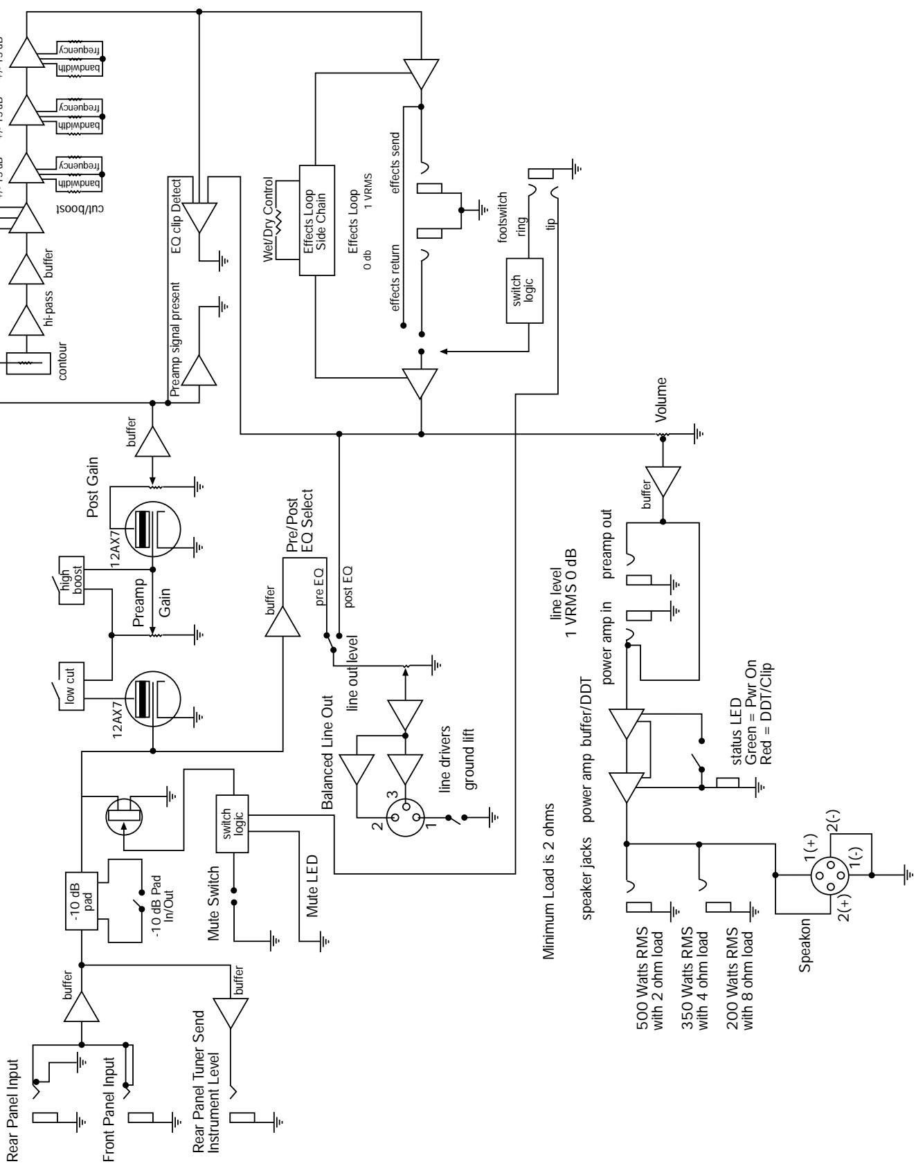
ProBass 500 Block Diagram
ESPAÑOL
PROBASS 500
Typically greater than -80 dB unweighted.
With controls set as follows:
Pad = passive
Bright = Normal (out)
Low Cut = Normal (out)
Pre Gain = 9 o'clock (roughly 2)
Post Gain = 10
Contour = 0
Low = 0
High = 0
Parametric Band 1: cut/boost = 0;
bandwidth = 0; frequency = 0
Parametric Band 2: cut/boost = 0;
bandwidth = 0; frequency = 0
Parametric Band 3: cut/boost = 0;
bandwidth = 0 ; frequency = 0
Master Volume = 5
POWER AMPLIFIER SECTION
Protection:
Electronic current limit protection circuit
Thermal protection circuit
D.C. crowbar protection circuit
DDT speaker protection circuit with
defeat switch and LED
Variable speed fan, thermally controlled
General Information:
Minimum Load = 2 Ohms
Input sensitivity: 1.o VRMS
Two 1/4" speaker jacks and one Neutrik
Speakon® all in parallel
Rated Power Output:
500 Watts (31.62 VRMS) into 2 Ohms
350 Watts (37.42 VRMS) into 4 Ohms
200 Watts (40.00 VRMS) into 8 Ohms
Noise:
Typically greater than 102 dB below full
power @ 8 Ohms unweighted
DDT Dynamic Range:
Typically greater than +15 dB
Frequency Response:
+0/-0.61 dB, 100mW to 160 w RMS 20 Hz
to 20kHz (8 Ohm load, typically below
0.2% THD+N)
PREAMP SECTION
Settings for measurements unless
otherwise noted:
Pad = passive (out)
Bright = Normal (out)
Low Cut = Normal (out)
Pre Gain = 2
Post Gain = 10
Contour = 0
Low = 0
High = 0
Parametric Band 1: cut/boost = 0;
bandwidth = 0 ; frequency = 12 o'clock
Parametric Band 2: cut/boost = 0;
bandwidth = 0 ; frequency = 12 o'clock
Parametric Band 3: cut/boost = 0;
bandwidth = 0 ; frequency = 12 o'clock
Master Volume = 5
Line Out Level = 10 (fully clockwise)
Input Sensitivity (level to achieve full power):
With Pad out:
Nominal input: 100 mV RMS
Minimum input: 5mV (pre gain @ 10)
Maximum input: 2.0 V (pre gain @ 1)
With Pad -10 dB in:
Nominal input: 316 mV RMS
Minimum input: 16mV (pre gain and
master fully CW)
Maximum input: 6.3 V (pre gain @ 1)
Equalization:
Bright Boost: +8 dB @ 5.5 kHz
Low Cut: -3 dB @ 125 Hz
Contour: Set @ 10 provides +4 dB @
35 Hz; -30 dB @ 400 Hz; +4 dB @
5.5 kHz
Low: + / - 15 dB @ 20 Hz; Shelving type EQ
High: +/-15 dB @ 5 kHz-20 kHz; Shelving
type EQ
Parametric Band 1: cut/boost = +12 dB/
-20 dB; BW (Q) = 0.3-8.5, Frequency = 40 Hz-400 Hz
Parametric Band 2: cut/boost = +12 dB/
-20 dB; BW (Q) = 0.3-8.5, Frequency = 150 Hz
Parametric Band 3: cut/boost = +12 dB/
-20 dB; BW (Q) = 0.3 - 8.5, Frequency =
800 Hz-8 kHz
Tuner Send:
Instrument level through a buffer
Line Out:
-∞ to fx loop level for post setting (for
nominal input)
-∞ to instrument level for pre setting (for
nominal input)
Effects Loop:
Set for -10 dB (0.315 VRMS) with post
gain @ 5; Master @ 10
Controlled via footswitch, ground tip to
defeat
Preamp Output:
1 VRMS nominal
Dimensions:
Width: 19.000" (48.26 cm)
Depth: 12.750" (32.39 cm)
Height: 3.500" (8.89 cm)
Weight: 24.8 lb (11.25 kg)
FRANÇAIS
PROBASS 500
14, 17, 20 cut/boost
40 line out level control
Typically greater than -80 dB unweighted.
With controls set as follows:
Pad = passive
Bright = Normal (out)
Low Cut = Normal (out)
Pre Gain = 9 o'clock (roughly 2)
Post Gain = 10
Contour = 0
Low = 0
High = 0
Parametric Band 1: cut/boost = 0;
bandwidth = 0; frequency = 0
Parametric Band 2: cut/boost = 0;
bandwidth = 0; frequency = 0
Parametric Band 3: cut/boost = 0;
bandwidth = 0 ; frequency = 0
Master Volume = 5
POWER AMPLIFIER SECTION
Protection:
Electronic current limit protection circuit
Thermal protection circuit
D.C. crowbar protection circuit
DDT speaker protection circuit with
defeat switch and LED
Variable speed fan, thermally controlled
General Information:
Minimum Load = 2 Ohms
Input sensitivity: 1.0 VRMS
Two 1/4" speaker jacks and one Neutrik
Speakon® all in parallel
Rated Power Output:
500 Watts (31.62 VRMS) into 2 Ohms
350 Watts (37.42 VRMS) into 4 Ohms
200 Watts (40.00 VRMS) into 8 Ohms
Noise:
Typically greater than 102 dB below full
power @ 8 Ohms unweighted
DDT Dynamic Range:
Typically greater than +15 dB
Frequency Response:
+0/-0.61 dB, 100mW to 160 w RMS 20 Hz
to 20kHz (8 Ohm load, typically below
0.2% THD+N)
PREAMP SECTION
Settings for measurements unless
otherwise noted:
Pad = passive (out)
Bright = Normal (out)
Low Cut = Normal (out)
Pre Gain = 2
Post Gain = 10
Contour = 0
Low = 0
High = 0
Parametric Band 1: cut/boost = 0;
bandwidth = 0 frequency = 12 o'clock
Parametric Band 2: cut/boost = 0;
bandwidth = 0 ; frequency = 12 o'clock
Parametric Band 3: cut/boost = 0;
bandwidth = o; frequency = 12 o'clock
Master Volume = 5
Line Out Level = 10 (fully clockwise)
Input Sensitivity (level to achieve full power):
With Pad out:
Nominal input: 100 mV RMS
Minimum input: 5mV (pre gain @ 10)
Maximum input: 2.0 V (pre gain @ 1)
With Pad -10 dB in:
Nominal input: 316 mV RMS
Minimum input: 16mV (pre gain and
master fully CW)
Maximum input: 6.3 V (pre gain @ 1)
Equalization:
Bright Boost: +8 dB @ 5.5 kHz
Low Cut: -3 dB @ 125 Hz
Contour: Set @ 10 provides +4 dB @
35 Hz; -30 dB @ 400 Hz; +4 dB @
5.5 kHz
Low: + / - 15 dB @ 20 Hz; Shelving type EQ
High: +/-15 dB @ 5 kHz-20 kHz; Shelving type EQ
Parametric Band 1: cut/boost = +12 dB/
-20 dB; BW (Q) = 0.3-8.5, Frequency = 40 Hz-400 Hz
Parametric Band 2: cut/boost = +12 dB/
-20 dB; BW (Q) = 0.3-8.5, Frequency = 150 Hz
Parametric Band 3: cut/boost = +12 dB/
-20 dB; BW (Q) = 0.3 - 8.5, Frequency =
800 Hz-8 kHz
Tuner Send:
Instrument level through a buffer
Line Out:
-∞ to fx loop level for post setting (for
nominal input)
-∞ to instrument level for pre setting (for
nominal input)
Effects Loop:
Set for -10 dB (0.315 VRMS) with post
gain @ 5; Master @ 10
Controlled via footswitch, ground tip to
defeat
Preamp Output:
1 VRMS nominal
Dimensions:
Width: 19.000" (48.26 cm)
Depth: 12.750" (32.39 cm)
Height: 3.500" (8.89 cm)
Weight: 24.8 lb (11.25 kg)
DEUTSCH
PROBASS 500
14, 17, 20 Cut/Boost
15, 18, 21 Bandwidth (Q)
16, 19, 22 Frequency
Typically greater than -80 dB unweighted.
With controls set as follows:
Pad = passive
Bright = Normal (out)
Low Cut = Normal (out)
Pre Gain = 9 o'clock (roughly 2)
Post Gain = 10
Contour = 0
Low = 0
High = 0
Parametric Band 1: cut/boost = 0;
bandwidth = 0; frequency = 0
Parametric Band 2: cut/boost = 0;
bandwidth = 0; frequency = 0
Parametric Band 3: cut/boost = 0;
bandwidth = 0 frequency = 0
Master Volume = 5
POWER AMPLIFIER SECTION
Protection:
Electronic current limit protection circuit
Thermal protection circuit
D.C. crowbar protection circuit
DDT speaker protection circuit with
defeat switch and LED
Variable speed fan, thermally controlled
General Information:
Minimum Load = 2 Ohms
Input sensitivity: 1.o VRMS
Two 1/4" speaker jacks and one Neutrik
Speakon® all in parallel
Rated Power Output:
500 Watts (31.62 VRMS) into 2 Ohms
350 Watts (37.42 VRMS) into 4 Ohms
200 Watts (40.00 VRMS) into 8 Ohms
Noise:
Typically greater than 102 dB below full
power @ 8 Ohms unweighted
DDT Dynamic Range:
Typically greater than +15 dB
Frequency Response:
+0/-0.61 dB, 100mW to 160 w RMS 20 Hz
to 20kHz (8 Ohm load, typically below
0.2% THD+N)
PREAMP SECTION
Settings for measurements unless
otherwise noted:
Pad = passive (out)
Bright = Normal (out)
Low Cut = Normal (out)
Pre Gain = 2
Post Gain = 10
Contour = 0
Low = 0
High = 0
Parametric Band 1: cut/boost = 0;
bandwidth = o; frequency = 12 o'clock
Parametric Band 2: cut/boost = 0;
bandwidth = 0 frequency = 12 o'clock
Parametric Band 3: cut/boost = 0;
bandwidth = o; frequency = 12 o'clock
Master Volume = 5
Line Out Level = 10 (fully clockwise)
Input Sensitivity (level to achieve full power):
With Pad out:
Nominal input: 100 mV RMS
Minimum input: 5mV (pre gain @ 10)
Maximum input: 2.0 V (pre gain @ 1)
With Pad -10 dB in:
Nominal input: 316mV RMS
Minimum input: 16mV (pre gain and
master fully CW)
Maximum input: 6.3 V (pre gain @ 1)
Equalization:
Bright Boost: +8 dB @ 5.5 kHz
Low Cut: -3 dB @ 125 Hz
Contour: Set @ 10 provides +4 dB @
35 Hz; -30 dB @ 400 Hz; +4 dB @
5.5 kHz
Low: + / - 15 dB @ 20 Hz; Shelving type EQ
High: +/-15 dB @ 5 kHz-20 kHz; Shelving type EQ
Parametric Band 1: cut/boost = +12 dB/
-20 dB; BW (Q) = 0.3-8.5, Frequency = 40 Hz-400 Hz
Parametric Band 2: cut/boost = +12 dB/
-20 dB; BW (Q) = 0.3-8.5, Frequency = 150 Hz
Parametric Band 3: cut/boost = +12 dB/
-20 dB; BW (Q) = 0.3 - 8.5, Frequency =
800 Hz-8 kHz
Tuner Send:
Instrument level through a buffer
Line Out:
- to fx loop level for post setting (for
nominal input)
-∞ to instrument level for pre setting (for nominal input)
Effects Loop:
Set for -10 dB (0.315 VRMS) with post
gain @ 5; Master @ 10
Controlled via footswitch, ground tip to
defeat
Preamp Output:
1 VRMS nominal
Dimensions:
Width: 19.000" (48.26 cm)
Depth: 12.750" (32.39 cm)
Height: 3.500" (8.89 cm)
Weight: 24.8 lb (11.25 kg)
What This Warranty Covers
Your Peavey Warranty covers defects in material and workmanship in Peavey products purchased and serviced in the U.S.A. and Canada.
What This Warranty Does Not Cover
The Warranty does not cover: (1) damage caused by accident, misuse, abuse, improper installation or operation, rental, product modification or neglect; (2) damage occurring during shipment; (3) damage caused by repair or service performed by persons not authorized by Peavey; (4) products on which the serial number has been altered, defaced or removed; (5) products not purchased from an Authorized Peavey Dealer.
Who This Warranty Protects
This Warranty protects only the original retail purchaser of the product.
How Long This Warranty Lasts
The Warranty begins on the date of purchase by the original retail purchaser. The duration of the Warranty is as follows:
| Product Category | Duration |
| Guitars/Basses, Amplifiers, Pre-Amplifiers, Mixers, Electronic Crossovers and Equalizers | 2 years * (+ 3 years) |
| Drums | 2 years * (+ 1 year) |
| Enclosures | 3 years * (+ 2 years) |
| Digital Effect Devices and Keyboard and MIDI Controllers | 1 year * (+ 1 year) |
| Microphones | 2 years |
| Speaker Components (incl. speakers, baskets, drivers, diaphragm replacement kits and passive crossovers) and all Accessories | 1 year |
| Tubes and Meters | 90 days |
[Denotes additional warranty period applicable if optional Warranty Registration Card is completed and returned to Peavey by original retail purchaser within 90 days of purchase.]
What Peavey Will Do
We will repair or replace (at Peavey's discretion) products covered by warranty at no charge for labor or materials. If the product or component must be shipped to Peavey for warranty service, the consumer must pay initial shipping charges. If the repairs are covered by warranty, Peavey will pay the return shipping charges.
How To Get Warranty Service
(a) Take the defective item and your sales receipt or other proof of date of purchase to your Authorized Peavey Dealer or Authorized Peavey Service Center. OR
(2) Ship the defective item, prepaid, to Peavey Electronics Corporation, International Service Center, 412 Highway 11 & 80 East, Meridian, MS 39301 or Peavey Canada Ltd., 95 Shields Court, Markham, Ontario, Canada L3R 9T5. Include a detailed description of the problem, together with a copy of your sales receipt or other proof of date of purchase as evidence of warranty coverage. Also provide a complete return address.
Limitation of Implied Warranties
ANY IMPLIED WARRANTY, INCLUDING WARRANTY OF MERCHANTABILITY AND FITNESS FOR A PARTICULAR PURPOSE, ARE LIMITED IN DURATION TO THE LENGTH OF THIS WARRANTY.
Some states do not allow limitations on how long an implied warranty lasts, so the above limitation may not apply to you.
Exclusions of Damages
PEAVEY'S LIABILITY FOR ANY DEFECTIVE PRODUCT IS LIMITED TO THE REPAIR OR REPLACEMENT OF THE PRODUCT, AT PEAVEY'S OPTION. IF WE ELECT TO REPLACE THE PRODUCT, THE REPLACEMENT MAY BE A RECONDITIONED UNIT. PEAVEY SHALL NOT BE LIABLE FOR DAMAGES BASED ON INCONVENIENCE, LOSS OF USE, LOST PROFITS, LOST SAVINGS, DAMAGE TO ANY OTHER EQUIPMENT OR OTHER ITEMS AT THE SITE OF USE, OR ANY OTHER DAMAGES WHEHTHER INCIDENTAL, CONSEQUENTIAL OR OTHERWISE, EVEN IF PEAVEY HAS BEEN ADVISED OF THE POSSIBILITY OF SUCH DAMAGES.
Some states do not allow the exclusion or limitation of incidental or consequential damages, so the above limitation or exclusion may not apply to you.
This Warranty gives you specific legal rights, and you may also have other rights which vary from state to state.
If you have any questions about this warranty or service received or if you need assistance in locating an Authorized Service Center, please contact the Peavey International Service Center at (601) 483-5365 / Peavey Canada Ltd. at (905) 475-2578.
FEATURES AND SPECIFICATIONS SUBJECT TO CHANGE WITHOUT NOTICE.

LISTEN TO THIS
Features and specifications subject to change without notice.
Peavey Electronics Corporation • 711 A Street • Meridian • MS • 39301
(601) 483-5365 • FAX (601) 486-1278 • www.peavey.com

80304909
- PROBASS 500 Operation Manual
- SAVE THESE INSTRUCTIONS!
- ENGLISH
- PROBASS 500
- Features
- mute switch
- mute status LED
- input jack
- input pad switch
- hi boost switch
- low cut switch
- pre gain
- post gain
- low
- high
- 11contour control
- signal status LED (green)
- signal clip indicator (red)
- 14-22 3-band parametric EQ
- 14, 17, 20 cut/boost
- 15, 18, 21 bandwidth (Q)
- 16, 19, 22 frequency
- Note about frequencies:
- master volume
- DDT™ enable/disable switch
- power LED/DDT indicator
- power switch
- ground polarity switch
- reset/circuit breaker switch
- IEC connector/detachable line cord
- speaker output jacks
- power amp input
- preamp out
- remote jack switch
- effects return
- effects send
- effects mix
- line out ground lift switch
- select switch
- line out (low Z balanced)
- 4o line out level control
- tunesendjack
- auxiliary input jack
- PROBASS 500™
- SPECIFICATIONS
- SYSTEM SPECIFICATIONS
- Mains Circuit Breaker:
- Mains Voltage:
- Power Consumption:
- Hum and Noise:
- POWER AMPLIFIER SECTION
- Protection:
- General Information:
- Rated Power Output:
- Noise:
- DDT Dynamic Range:
- Frequency Response:
- PREAMP SECTION
- Input Sensitivity (level to achieve full power):
- Equalization:
- Tuner Send:
- Line Out:
- Effects Loop:
- Preamp Output:
- Dimensions:
- SUGGESTED SETTINGS
- Note:
- lay.it.down
- phunk.101
- ESPAÑOL
- FRANÇAIS
- line out level control
- DEUTSCH
- What This Warranty Covers
- What This Warranty Does Not Cover
- Who This Warranty Protects
- How Long This Warranty Lasts
- What Peavey Will Do
- How To Get Warranty Service
- Limitation of Implied Warranties
- Exclusions of Damages
Brand : PEAVEY
Model : PROBASS 500
Category : Bass Amplifier