
T-MAX - Bass Amplifier PEAVEY - Free user manual and instructions
Find the device manual for free T-MAX PEAVEY in PDF.

| Product Type | Bass Amplifier |
| Brand | PEAVEY |
| Model | T-MAX |
| Mains Power Supply | 220-240 V, 50/60 Hz, 900 W |
| Output Power | 550 W (33.17 V RMS into 2 Ω min) |
| Minimum Load Impedance | 2 Ω |
| Protection | Resettable Thermal Circuit Breaker |
| Operation Indicator | Green LED (on) / Red LED (DDT™ compression) |
| Graphic Equalizer | On/Off switch (in/out) |
| Line Output | Balanced XLR, low impedance, selectable pre or post EQ |
| Effects Loop | Switchable level -10 dBV / 0 dBV |
| Remote Control | DIN connector for optional footswitch (channel select, EQ, loop) |
| Crossover | Post-crossover low and high frequency outputs, gain controls |
| Speaker Outputs | Paralleled jacks, minimum total impedance 2 Ω |
| Ground Lift | GND Lift switch to eliminate hum |
| Safety | Do not open, do not expose to rain or humidity |
| Maintenance and Cleaning | Refer servicing to qualified personnel |
| Spare Parts and Repairability | Contact an authorized repair center |
| General Information | Manufactured in the United States under U.S. Patent No. 4,318,053 |
Frequently Asked Questions - T-MAX PEAVEY
User questions about T-MAX PEAVEY
0 question about this device. Answer the ones you know or ask your own.
Ask a new question about this device
Download the instructions for your Bass Amplifier in PDF format for free! Find your manual T-MAX - PEAVEY and take your electronic device back in hand. On this page are published all the documents necessary for the use of your device. T-MAX by PEAVEY.
USER MANUAL T-MAX PEAVEY
Intended to alert the user to the presence of uninsulated "dangerous voltage" within the product's enclosure that may be of sufficient magnitude to constitute a risk of electric shock to persons.

Intended to alert the user of the presence of important operating and maintenance (servicing) instructions in the literature accompanying the product.
CAUTION: Risk of electrical shock – DO NOT OPEN!
CAUTION: To reduce the risk of electric shock, do not remove cover. No user serviceable parts inside. Refer servicing to qualified service personnel.
WARNING: To prevent electrical shock or fire hazard, do not expose this appliance to rain or moisture. Before using this appliance, read the operating guide for further warnings.

Congratulations on the purchase of the Peavey T-MAX ® bass amp! The two channel bass system is unlike any other amp available today. Not only does the T-MAX utilize tube technology for that smooth tube sound, but the T-MAX also has a completely independent solid-state channel! Two separate channels that are footswitchable and combinable make for an extremely versatile piece of gear. Besides the clean contemporary sound, the T-MAX is also capable of producing a smooth tube-distortion sound that can't be found in any modern solid-state bass rig!
FEATURES:
- 1/4" input with -10 dB pad switch
- Active low- and high-shelving EQ with 7-band graphic EQ
– Front panel channel select and channel combine switches - Channel active LEDs
– Variable (100 Hz - 1 kHz) third-octave crossover with frequency and balance controls - Front panel graphic in/out switch
- Footswitchable: channel select, graphic in/out, and effects loop
– Low Z balanced line out with pre/post EQ switch
– Ground lift switch for line out - Two paralleled speaker jacks
- Preamp out/power amp in jacks
– Crossover low and high out jacks
– Effects send and return jacks
– Effects high and low level switch - Two-rack-space package
ENGLISH
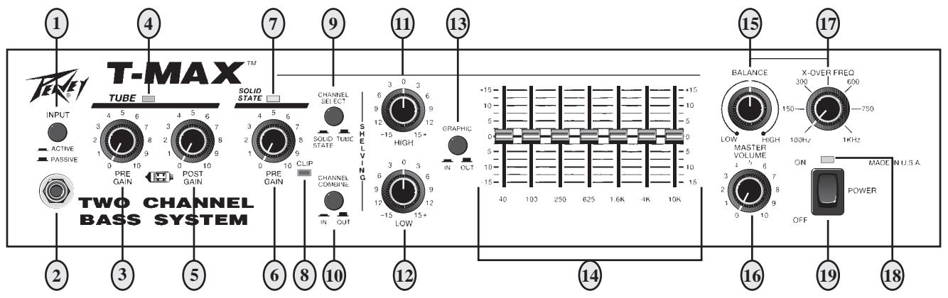
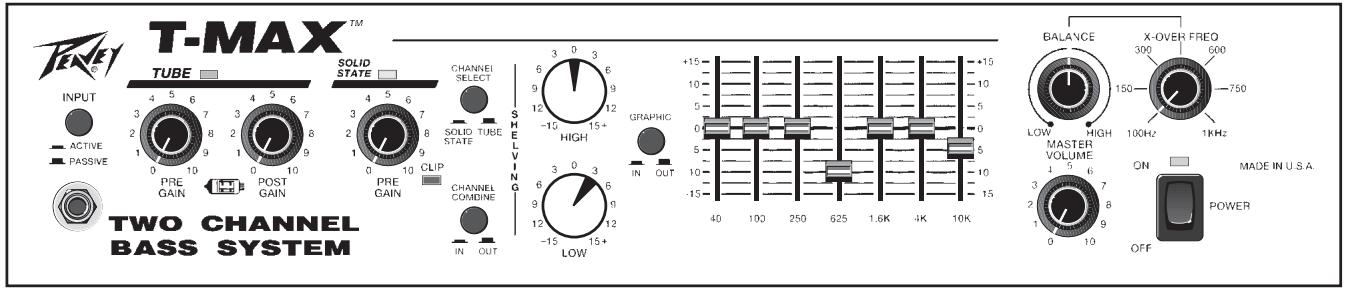
INPUT PAD SWITCH (1)
Provided for instruments that have extremely high output, which can result in overdriving (distorting) the input gain stage. Depressing the switch to its "in" position reduces the level of the input signal by 10 dB.
INPUT (2)
This input will accept signals from all types of bass pickups.
PRE GAIN (3)
Controls the input gain of the tube channel.
CHANNEL STATUS LED (4)
Illuminates when channel is activated.
POST GAIN (5)
Controls the overall volume level of the channel. The master volume adjustment should be made after the desired sound has been achieved.
PRE GAIN (6)
Controls the input gain of the solid-state channel.
CHANNEL STATUS LED (7)
Illuminates when channel is activated.
INPUT CLIP INDICATOR (8)
This LED indicates (when lit) that the input gain stage is being overdriven (distorted). Depressing the input pad switch to its "in" position or reducing the pre gain will alleviate this problem.
CHANNEL SELECT SWITCH (9)
Allows selection of the tube or solid-state channel. The "in" position of the switch selects the solid-state channel, and the "out" position selects the tube channel.
NOTE: Channel selection may also be accomplished by the remote footswitch. If the remote selection is desired, the select switch must be in the "out" (tube) position.
CHANNEL COMBINE SWITCH (10)
Allows selection of single channel or combined channel operation. The "in" position of the switch selects combined channel operation where both channels operate simultaneously. The "out" position selects single channel operation.
HIGH (11)
An active tone control (shelving type, ±15 dB) that varies the high frequency boost or cut.
LOW (12)
An active tone control (shelving type, ±15 dB) that varies the low frequency boost or cut.
GRAPHIC SELECT (13)
The "in" position of this switch routes the signal through the graphic equalizer. The "out" position removes the graphic equalizer from the signal path.
7-BAND GRAPHIC EQ (14)
A 7-band, two-and-one-half-octave graphic equalizer that provides 15 dB of boost or cut at each center frequency.
CROSSOVER BALANCE CONTROL (15)
Controls the relative levels of output signals from the crossover. Adjusting this control will only affect signals at the High Range Output Jack and the Low Range Output Jack on the rear panel. All other output signals are unaffected by this control.
MASTER VOLUME (16)
Controls the overall volume level of the system.
The frequency control varies the crossover frequency from 100 Hz to 1 kHz.
POWER LED/DDT™ INDICATOR (18)
The LED is green when the power switch is in the "on" position. During normal operation, this LED also acts as a DDT TM indicator. The LED illuminates "red" when DDT TM power amp compression is taking place.
POWER SWITCH (19)
Used to turn AC mains power on or off.
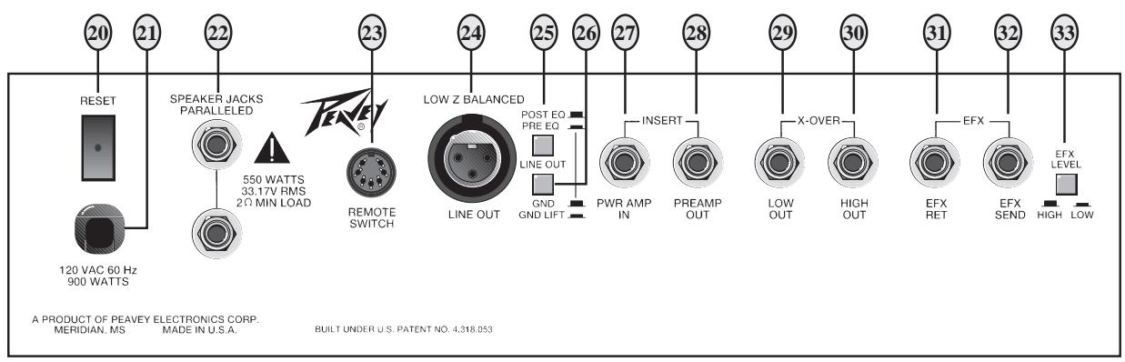
CIRCUIT BREAKER (20)
This breaker is provided to limit the current to the power transformer, and thereby protect it from overheating and possible destruction due to faulty conditions in the amplifier. The trip current value has been carefully chosen to allow continuous power output performance, while still providing adequate protection for the power transformer. Normally this breaker should not trip unless there is a fault in the amplifier circuitry that draws excessive mains current. However, abnormal conditions, such as a short circuit or continuous operation at overload or clipping, will cause the breaker to trip. If this occurs, simply reset the breaker and correct the cause of the overload. When tripped, the button on the breaker will be outward nearly 1/2" and can be reset by pushing inward. A normal reset button length is about 1/4". If this "thermal" type breaker does trip, then simply pushing the button back in will reset it after waiting a brief period of time to allow it to cool down. If the breaker trips instantly each time you attempt to reset it, then the unit should be taken to a qualified service center for repair.
LINE CORD (120 V PRODUCTS ONLY) (21)
For your safety, we have incorporated a 3-wire line (mains) cable with proper grounding facilities. It is not advisable to remove the ground pin under any circumstances. If it is necessary to use the equipment without proper grounding facilities, suitable grounding adaptors should be used. Less noise and greatly reduced shock hazard exist when the unit is operated with the proper grounded receptacles.
SPEAKER JACKS (22)
Provided for connection of external speakers or speaker enclosure. Minimum total impedance is 2 ohms.
REMOTE SWITCH DIN JACK (23)
Provided for optional footswitch. Allows remote selection of channel select, graphic in/out, and effects loop (post EQ).
LINE OUT (LOW Z BALANCED) (24)
An XLR jack is provided to route the signal to mixing/recording consoles. This output can be selected pre or post EQ.
LINE OUT SELECT SWITCH (25)
Allows selection of pre EQ or post EQ to the Low Z balanced line out jack. The “in” position selects pre EQ line out, and the “out” position selects post EQ line out.
LINE OUT GROUND LIFT SWITCH (26)
Provides ground to be made from the line out jack or lifted to eliminate ground loop from unit and external source. There may be some situations when audible hum and/or noise will come from the loudspeaker. Select the ground switch to either the in or out position to minimize the noise.
POWER AMP INPUT (27)
Used to connect line level signal to the power amplifier.
PREAMP OUT (28)
The preamp output can be used to route the amplified signal to a mixing console, tape recorder, etc. Connect the preamp output using a shielded cable to an input of the tape recorder, mixer, etc. This patch does not affect the operation of the amplifier.
CROSSOVER (LOW OUT) (29)
Provides a post crossover low-range output signal. Signal level is adjusted by the master volume control and the crossover balance control.
CROSSOVER (HIGH OUT) (30)
Provides a post crossover high range output signal. Signal level is adjusted by the master volume control and the crossover balance control.
EFFECTS RETURN (31)
Input for returning signals from external low-level effects or signal processing equipment.
EFFECTS SEND (32)
Output for supplying signals to external low-level effects or signal processing equipment.
EFX LEVEL SWITCH (33)
Selects the effects loop operating level: -10 dBV (3 V RMS) when in low position and 0 dBV (1 V RMS) when in high position.
SPECIFICATIONS
POWER AMP SECTION
Power Output with DDT™
Compression Active:
200 W RMS into 8 ohms
350 W RMS into 4 ohms
500 W RMS into 2 ohms
Input Sensitivity:
Input signal necessary for full output = 1.7 V RMS
DDT™ Dynamic Range:
Greater than 20 dB
DDT™ Maximum THD:
Below 0.6% THD for 6 dB overload Below 1% THD for 16 dB overload
Hum & Noise:
Greater than 95 dB below rated power
Power Consumption:
Domestic: 900 watts @ 120 V AC, 60 Hz
Export: 900 watts @ 220-240 V AC, 50/60 Hz
PREAMP SECTION
All measurements are with the following settings except where noted.
Note: Tube channel is designed to produce distortion when pre gain control is set greater than 3 (dependent on input signal).
Note: All signals referenced to 1 V RMS = 0 dB.
Solid-State Pre Gain @ 5
Master Volume @ 5
-10 dB Pad Out
All EQ Sliders @ 0 (Centered)
Low and High Shelving @ 0
Input Signal Levels:
Solid-State Channel, -10 dB Pad Out
Nominal Input: 0.14 V RMS, -17 dB
Minimum Input: 16 mV RMS, -36 dB
Maximum Input: 2.0 V RMS, +6 dB
Solid-State Channel, -10 dB Pad In
Nominal Input: 0.422 V RMS, -7.5 dB
Minimum Input: 50 mV RMS, -26 dB
Maximum Input: 6.0 V RMS, +15.5 dB
Tube Channel, -10 dB Pad Out, Post Gain @ 5
Nominal Input: 0.054 V RMS, -25.3 dB
Minimum Input: 5 mV RMS, -46 dB (Post Gain @ 10)
Maximum Input: 1.0 V RMS, +0 dB (For Clean Signal)
Tube Channel, - 10 dB Pad In
Nominal Input: 0.160 V RMS, -16 dB
Minimum Input: 15 mV RMS, -36.5 dB (Post Gain @ 10)
Maximum Input: 3 V RMS, +9.5 dB (For Clean Signal)
Effects Loop (Post EQ):
Send Level (High Setting): -7 dB
Send Level (Low Setting): -15 dB
Return Level (High Setting): -7 dB
Return Level (Low Setting): -15 dB
Crossover:
Low Output Levels:
Nominal: 1.7 V RMS, 4.6 dB
Maximum: 8 V RMS, +18 dB
High Output Levels:
Nominal: 1.7 V RMS, 4.6 dB
Maximum: 8 V RMS, +18 dB
Full Range Output Levels:
Nominal: 1.7 V RMS, 4.6 dB
Maximum: 8 V RMS, +18 dB
Frequency:
Variable from 100 Hz to 1 kHz
Balanced Out:
Pre EQ: -1.35 dB from input jack, -20 dB from full range output (-10 dB Pad Out)
Post EQ: -7 dB nominal, +15.5 dB maximum
Note: Post EQ balanced output taken before master volume, Pre EQ balanced output buffered off input jack.
Equalization:
Graphic Equalizer: ±15 dB @ 40, 100, 250, 625, 1.6 K, 4 K, 10 K
Shelving Controls:
±15 dB high shelving @ 8 kHz
±15 dB low shelving @ 20 Hz
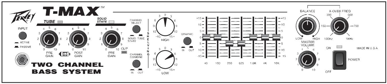
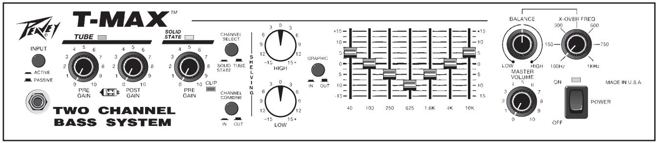
TONE SETTINGS
Set Pre and Post Gain so that clip indicator does not light; then use Master Volume for playing level.
ROCK
FUNK
COUNTRY
NOTE: Above settings for use with Solid-State or Tube Channel.
NOTES FOR TUBE CHANNEL:
Distortion: Set Pre Gain very high — usually above 5. Keep Post Gain set low.
Clean: Set Post Gain @ 10 and set Pre Gain low — below 5.
ESPAÑOL
For further information on other Peavey products, ask your Authorized Peavey Dealer for the appropriate Peavey catalog/publication:
Bass Guitars
Guitars
Bass Amplification
Guitar Amplification
Sound Reinforcement Enclosures
Microphones
Keyboards
DJ
Lighting
Mixers, Powered/Non-Powered
Accessories/Cables
Effects Processors
Axcess™ Wear
The Peavey Beat TM
Monitor® Magazine
Key Issues™
Low Down™
PM™ Magazine
THIS LIMITED WARRANTY VALID ONLY WHEN PURCHASED AND REGISTERED IN THE UNITED STATES OR CANADA. ALL EXPORTED PRODUCTS ARE SUBJECT TO WARRANTY AND SERVICES TO BE SPECIFIED AND PROVIDED BY THE AUTHORIZED DISTRIBUTOR FOR EACH COUNTRY.
PEAVEY ELECTRONICS CORPORATION (“PEAVEY”) warrants this product, EXCEPT for covers, footswitches, patchcords, tubes and meters, to be free from defects in material and workmanship for a period of one (1) year from date of purchase, PROVIDED, however, that this limited warranty is extended only to the original retail purchaser and is subject to the conditions, exclusions, and limitations hereinafter set forth:
PEAVEY 90-DAY LIMITED WARRANTY ON TUBES AND METERS
If this product contains tubes or meters, Peavey warrants the tubes or meters contained in the product to be free from defects in material and workmanship for a period of ninety (90) days from date of purchase; PROVIDED, however, that this limited warranty is extended only to the original retail purchaser and is also subject to the conditions, exclusions, and limitations hereinafter set forth.
CONDITIONS, EXCLUSIONS, AND LIMITATIONS OF LIMITED WARRANTIES
These limited warranties shall be void and of no effect, if:
a. The first purchase of the product is for the purpose of resale; or
b. The original retail purchase is not made from an AUTHORIZED PEAVEY DEALER; or
c. The product has been damaged by accident or unreasonable use, neglect, improper service or maintenance, or other causes not arising out of defects in material or workmanship; or
d. The serial number affixed to the product is altered, defaced, or removed.
In the event of a defect in material and/or workmanship covered by this limited warranty, Peavey will:
a. In the case of tubes or meters, replace the defective component without charge.
b. In other covered cases (i.e., cases involving anything other than covers, footswitches, patchcords, tubes or meters), repair the defect in material or workmanship or replace the product, at Peavey's option; and provided, however, that, in any case, all costs of shipping, if necessary, are paid by you, the purchaser.
THE WARRANTY REGISTRATION CARD SHOULD BE ACCURATELY COMPLETED AND MAILED TO AND RECEIVED BY PEAVEY WITHIN FOURTEEN (14) DAYS FROM THE DATE OF YOUR PURCHASE.
In order to obtain service under these warranties, you must:
a. Bring the defective item to any PEAVEY AUTHORIZED DEALER or AUTHORIZED PEAVEY SERVICE CENTER and present therewith the ORIGINAL PROOF OF PURCHASE supplied to you by the AUTHORIZED PEAVEY DEALER in connection with your purchase from him of this product. If the DEALER or SERVICE CENTER is unable to provide the necessary warranty service you will be directed to the nearest other PEAVEY AUTHORIZED DEALER or AUTHORIZED PEAVEY SERVICE CENTER which can provide such service.
OR
b. Ship the defective item, prepaid, to:
PEAVEY ELECTRONICS CORPORATION
International Service Center
326 Hwy. 11 & 80 East
MERIDIAN, MS 39301
including therewith a complete, detailed description of the problem, together with a legible copy of the original PROOF OF PURCHASE and a complete return address. Upon Peavey's receipt of these items:
If the defect is remedial under these limited warranties and the other terms and conditions expressed herein have been complied with, Peavey will provide the necessary warranty service to repair or replace the product and will return it, FREIGHT COLLECT, to you, the purchaser.
Peavey's liability to the purchaser for damages from any cause whatsoever and regardless of the form of action, including negligence, is limited to the actual damages up to the greater of \$500.00 or an amount equal to the purchase price of the product that caused the damage or that is the subject of or is directly related to the cause of action. Such purchase price will be that in effect for the specific product when the cause of action arose. This limitation of liability will not apply to claims for personal injury or damage to real property or tangible personal property allegedly caused by Peavey's negligence. Peavey does not assume liability for personal injury or property damage arising out of or caused by a non-Peavey alteration or attachment, nor does Peavey assume any responsibility for damage to interconnected non-Peavey equipment that may result from the normal functioning and maintenance of the Peavey equipment.
UNDER NO CIRCUMSTANCES WILL PEAVEY BE LIABLE FOR ANY LOST PROFITS, LOST SAVINGS, ANY INCIDENTAL DAMAGES, OR ANY CONSEQUENTIAL DAMAGES ARISING OUT OF THE USE OR INABILITY TO USE THE PRODUCT, EVEN IF PEAVEY HAS BEEN ADVISED OF THE POSSIBILITY OF SUCH DAMAGES.
THESE LIMITED WARRANTIES ARE IN LIEU OF ANY AND ALL WARRANTIES, EXPRESSED OR IMPLIED, INCLUDING, BUT NOT LIMITED TO, THE IMPLIED WARRANTIES OF MERCHANTABILITY AND FITNESS FOR A PARTICULAR USE; PROVIDED, HOWEVER, THAT IF THE OTHER TERMS AND CONDITIONS NECESSARY TO THE EXISTENCE OF THE EXPRESSED, LIMITED WARRANTIES, AS HEREINABOVE STATED, HAVE BEEN COMPLIED WITH, IMPLIED WARRANTIES ARE NOT DISCLAIMED DURING THE APPLICABLE ONE-YEAR OR NINETY-DAY PERIOD FROM DATE OF PURCHASE OF THIS PRODUCT.
SOME STATES DO NOT ALLOW LIMITATION ON HOW LONG AN IMPLIED WARRANTY LASTS, OR THE EXCLUSION OR LIMITATION OF INCIDENTAL OR CONSEQUENTIAL DAMAGES, SO THE ABOVE LIMITATIONS OR EXCLUSIONS MAY NOT APPLY TO YOU. THESE LIMITED WARRANTIES GIVE YOU SPECIFIC LEGAL RIGHTS, AND YOU MAY ALSO HAVE OTHER RIGHTS WHICH MAY VARY FROM STATE TO STATE.
THESE LIMITED WARRANTIES ARE THE ONLY EXPRESSED WARRANTIES ON THIS PRODUCT, AND NO OTHER STATEMENT, REPRESENTATION, WARRANTY, OR AGREEMENT BY ANY PERSON SHALL BE VALID OR BINDING UPON PEAVEY.
In the event of any modification or disclaimer of expressed or implied warranties, or any limitation of remedies, contained herein conflicts with applicable law, then such modification, disclaimer or limitation, as the case may be, shall be deemed to be modified to the extent necessary to comply with such law.
Your remedies for breach of these warranties are limited to those remedies provided herein and Peavey Electronics Corporation gives this limited warranty only with respect to equipment purchased in the United States of America.
INSTRUCTIONS — WARRANTY REGISTRATION CARD
- Mail the completed WARRANTY REGISTRATION CARD to:
PEAVEY ELECTRONICS CORPORATION
a. Keep the PROOF OF PURCHASE. In the event warranty service is required during the warranty period, you will need this document. There will be no identification card issued by Peavey Electronics Corporation.
2. IMPORTANCE OF WARRANTY REGISTRATION CARDS AND NOTIFICATION OF CHANGES OF ADDRESSES:
a. Completion and mailing of WARRANTY REGISTRATION CARDS — Should notification become necessary for any condition that may require correction, the REGISTRATION CARD will help ensure that you are contacted and properly notified.
b. Notice of address changes – If you move from the address shown on the WARRANTY REGISTRATION CARD, you should notify Peavey of the change of address so as to facilitate your receipt of any bulletins or other forms of notification which may become necessary in connection with any condition that may require dissemination of information or correction.
3. You may contact Peavey directly by telephoning (601) 483-5365.
IMPORTANT SAFETY INSTRUCTIONS
WARNING: When using electric products, basic cautions should always be followed, including the following.
- Read all safety and operating instructions before using this product.
- All safety and operating instructions should be retained for future reference.
- Obey all cautions in the operating instructions and on the back of the unit.
- All operating instructions should be followed.
- This product should not be used near water, i.e., a bathtub, sink, swimming pool, wet basement, etc.
- This product should be located so that its position does not interfere with its proper ventilation. It should not be placed flat against a wall or placed in a built-in enclosure that will impede the flow of cooling air.
- This product should not be placed near a source of heat such as a stove, radiator, or another heat producing amplifier.
- Connect only to a power supply of the type marked on the unit adjacent to the power supply cord.
-
Never break off the ground pin on the power supply cord. For more information on grounding, write for our free booklet “Shock Hazard and Grounding.”
-
Power supply cords should always be handled carefully. Never walk or place equipment on power supply cords. Periodically check cords for cuts or signs of stress, especially at the plug and the point where the cord exits the unit.
-
The power supply cord should be unplugged when the unit is to be unused for long periods of time.
-
If this product is to be mounted in an equipment rack, rear support should be provided.
-
Metal parts can be cleaned with a damp rag. The vinyl covering used on some units can be cleaned with a damp rag or an ammonia-based household cleaner if necessary. Disconnect unit from power supply before cleaning.
-
Care should be taken so that objects do not fall and liquids are not spilled into the unit through the ventilation holes or any other openings.
-
This unit should be checked by a qualified service technician if:
a. The power supply cord or plug has been damaged.
b. Anything has fallen or been spilled into the unit.
c. The unit does not operate correctly.
d. The unit has been dropped or the enclosure damaged.
-
The user should not attempt to service this equipment. All service work should be done by a qualified service technician.
-
This product should be used only with a cart or stand that is recommended by Peavey Electronics.
-
Exposure to extremely high noise levels may cause a permanent hearing loss. Individuals vary considerably in susceptibility to noise induced hearing loss, but nearly everyone will lose some hearing if exposed to sufficiently intense noise for a sufficient time. The U.S. Government's Occupational Safety and Health Administration (OSHA) has specified the following permissible noise level exposures.
| Duration Per Day In Hours | Sound Level dBA, Slow Response |
| 8 | 90 |
| 6 | 92 |
| 4 | 95 |
| 3 | 97 |
| 2 | 100 |
| 1 1/2 | 102 |
| 1 | 105 |
| 1/2 | 110 |
| 1/4 or less | 115 |
According to OSHA, any exposure in excess of the above permissible limits could result in some hearing loss.
Ear plugs or protectors in the ear canals or over the ears must be worn when operating this amplification system in order to prevent a permanent hearing loss if exposure is in excess of the limits as set forth above. To ensure against potentially dangerous exposure to high sound pressure levels, it is recommended that all persons exposed to equipment capable of producing high sound pressure levels such as this amplification system be protected by hearing protectors while this unit is in operation.
SAVE THESE INSTRUCTIONS!

Commercial Audio Equipment 25E9

natural_image
Abstract black geometric logo design with stylized arrow-like shapes (no text or symbols)Features and specifications subject to change without notice.
- FEATURES:
- ENGLISH
- INPUT PAD SWITCH (1)
- INPUT (2)
- PRE GAIN (3)
- CHANNEL STATUS LED (4)
- POST GAIN (5)
- PRE GAIN (6)
- CHANNEL STATUS LED (7)
- INPUT CLIP INDICATOR (8)
- CHANNEL SELECT SWITCH (9)
- CHANNEL COMBINE SWITCH (10)
- HIGH (11)
- LOW (12)
- GRAPHIC SELECT (13)
- 7-BAND GRAPHIC EQ (14)
- CROSSOVER BALANCE CONTROL (15)
- MASTER VOLUME (16)
- POWER LED/DDT™ INDICATOR (18)
- POWER SWITCH (19)
- CIRCUIT BREAKER (20)
- LINE CORD (120 V PRODUCTS ONLY) (21)
- SPEAKER JACKS (22)
- REMOTE SWITCH DIN JACK (23)
- LINE OUT (LOW Z BALANCED) (24)
- LINE OUT SELECT SWITCH (25)
- LINE OUT GROUND LIFT SWITCH (26)
- POWER AMP INPUT (27)
- PREAMP OUT (28)
- CROSSOVER (LOW OUT) (29)
- CROSSOVER (HIGH OUT) (30)
- EFFECTS RETURN (31)
- EFFECTS SEND (32)
- EFX LEVEL SWITCH (33)
- SPECIFICATIONS
- POWER AMP SECTION
- Power Output with DDT™
- Compression Active:
- Input Sensitivity:
- DDT™ Dynamic Range:
- DDT™ Maximum THD:
- Hum & Noise:
- Power Consumption:
- PREAMP SECTION
- Input Signal Levels:
- Solid-State Channel, -10 dB Pad Out
- Solid-State Channel, -10 dB Pad In
- Tube Channel, -10 dB Pad Out, Post Gain @ 5
- Tube Channel, - 10 dB Pad In
- Effects Loop (Post EQ):
- Crossover:
- Low Output Levels:
- High Output Levels:
- Full Range Output Levels:
- Frequency:
- Balanced Out:
- Equalization:
- TONE SETTINGS
- NOTES FOR TUBE CHANNEL:
- ESPAÑOL
- For further information on other Peavey products, ask your Authorized Peavey Dealer for the appropriate Peavey catalog/publication:
- THIS LIMITED WARRANTY VALID ONLY WHEN PURCHASED AND REGISTERED IN THE UNITED STATES OR CANADA. ALL EXPORTED PRODUCTS ARE SUBJECT TO WARRANTY AND SERVICES TO BE SPECIFIED AND PROVIDED BY THE AUTHORIZED DISTRIBUTOR FOR EACH COUNTRY.
- PEAVEY 90-DAY LIMITED WARRANTY ON TUBES AND METERS
- CONDITIONS, EXCLUSIONS, AND LIMITATIONS OF LIMITED WARRANTIES
- OR
- PEAVEY ELECTRONICS CORPORATION
- INSTRUCTIONS — WARRANTY REGISTRATION CARD
- IMPORTANT SAFETY INSTRUCTIONS
- SAVE THESE INSTRUCTIONS!
Brand : PEAVEY
Model : T-MAX
Category : Bass Amplifier