
ECOUSTIC 112 - Acoustic amplifier PEAVEY - Free user manual and instructions
Find the device manual for free ECOUSTIC 112 PEAVEY in PDF.

| Product type | Acoustic amplifier |
| Brand | PEAVEY |
| Model | ECOUSTIC 112 |
| Speaker | Coaxial woofer 30.48 cm (12 in) and soft dome tweeter |
| Number of channels | 2 (instrument channel and mic channel) |
| Equalization | 5-band active per channel |
| Reverb | Built-in, separate per-channel and master settings |
| Feedback elimination | Frequency sweep with notch filter (40 Hz to 2 kHz), phase inversion switch |
| Instrument inputs | 6.35 mm (1/4 in) jack with level switch |
| Microphone inputs | Low-Z (XLR) and High-Z (6.35 mm) simultaneous |
| Direct output | Balanced XLR with pre/post-EQ selection |
| Additional outputs | Preamp out, Power amp in, effects loops (send/return) for mic and instrument |
| Remote control | Footswitch jack (optional): effects loop bypass and standby |
| Power supply | 120 V AC, 3-wire grounded cable |
| Safety instructions | Do not open the device, do not expose to rain or moisture, refer servicing to qualified personnel |
| Usage | Acoustic guitar, microphone, percussion, keyboards, vocals |
Frequently Asked Questions - ECOUSTIC 112 PEAVEY
User questions about ECOUSTIC 112 PEAVEY
0 question about this device. Answer the ones you know or ask your own.
Ask a new question about this device
Download the instructions for your Acoustic amplifier in PDF format for free! Find your manual ECOUSTIC 112 - PEAVEY and take your electronic device back in hand. On this page are published all the documents necessary for the use of your device. ECOUSTIC 112 by PEAVEY.
USER MANUAL ECOUSTIC 112 PEAVEY
Intended to alert the user to the presence of uninsulated "dangerous voltage" within the product's enclosure that may be of sufficient magnitude to constitute a risk of electric shock to persons.

Intended to alert the user of the presence of important operating and maintenance (servicing) instructions in the literature accompanying the product.
CAUTION: Risk of electrical shock - DO NOT OPEN!
CAUTION: To reduce the risk of electric shock, do not remove cover. No user serviceable parts inside. Refer servicing to qualified service personnel.
WARNING: To prevent electrical shock or fire hazard, do not expose this appliance to rain or moisture. Before using this appliance, read the operating guide for further warnings.

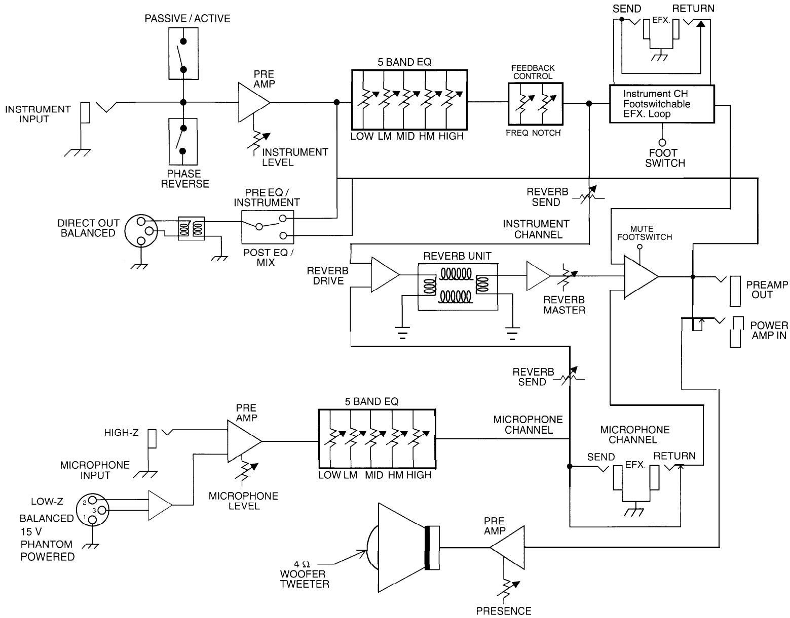
Congratulations on your purchase of the Ecoustic™ 112. This amplifier is primarily designed for acoustic guitars but works equally well with other acoustic instruments, vocals, drum machines, keyboards, or any other source requiring full-range amplification. The coaxial, 12-inch woofer/soft dome tweeter combination creates a system with uncompromised lows and very smooth highs. The 5-band active equalization on each of the two channels, when used with their individual effects loops and on-board spring reverb, allows for complete control of the tonal balance of the instrument, vocal, etc.
The primary Instrument Channel has a specially designed feedback elimination system that includes a phase reversal switch, and a frequency sweepable notch system that allows for exact placement on the problem frequency without reducing the volume in the surrounding frequency band. This system is roughly equivalent to having a single band from a 31-band, 1/3 octave EQ that can be swept from 40Hz to 2kHz .
The Microphone Channel includes a phantom-powered balance Low-Z input and a High-Z input that works simultaneously to allow the use of either type microphone and/or other sources, such as drum machines, keyboards, tape decks, etc. The equalization is identical to that on the Instrument Channel, making this channel a second guitar input. A commonly used method for amplifying acoustic guitar is to mic the instrument and mix it with the piezo output. By using the phase switch on the Instrument Channel, the user can easily mix the two with the appropriate phase so as not to cancel any lows.
The inclusion of a transformer-balanced direct output allows the signal to be fed to a mixer either from the Input of the Instrument Channel or from the preamp out, which contains the sum of the Instrument and Mic Channels.
FRONT PANEL FEATURES
INPUT (1)
A 1/4'' instrument jack is provided with extremely wide dynamic range. This input will accept very high level signals or very low signals from any type acoustic instrument.
PASSIVE/ACTIVE SWITCH (2)
Reduces system gain when pressed to allow for greater dynamic range when using instruments with high output built-in preamps.
PHASE REVERSE SWITCH (3)
Reverses the phase of the instrument signal in order to reduce feedback or to correct out-of-phase conditions when using both the Instrument Input and Mic Input on a single instrument.
INSTRUMENT LEVEL (4)
Control is the overall volume level of the Instrument Channel.
EQUALIZATION—INSTRUMENT CHANNEL (5)
Specially designed 5-band, active equalization.
FREQUENCY (6)
Provides selectable frequency shift of notch filter from 40Hz to 2kHz to eliminate acoustical instrument feedback.
NOTCH (7)
Variable notch control used in conjunction with frequency shift to provide the proper notch setting required to eliminate feedback from instrument. (The more counter clockwise, the deeper the notch, i.e. the notch is out of the circuit when the control is set at full clockwise position.)
REVERB SEND-INSTRUMENT CHANNEL (8)
Controls the amount of reverb signal from the Instrument Channel. Reverb is an echo type effect.
MIC INPUT/LOW-Z (9)
For use with low impedance microphones or high-level sources equipped with a male XLR connector.
Phantom power allows use of microphones that require phantom power.
MIC INPUT/HIGH-Z (10)
For use with high impedance microphones or high-level sources equipped with a 1/4" phone plug.
MIC LEVEL (11)
Controls the overall volume level of the Microphone Channel.
EQUALIZATION-MIC CHANNEL (12)
Specially designed 5-band, active equalization.
REVERB SEND-MIC CHANNEL (13)
Controls the amount of reverb signal from the Microphone Channel.
MASTER REVERB (14)
Controls the overall amount of reverb signal for both the Instrument and Microphone Channels.
PRESENCE (15)
This is an active tone control that boosts the extreme high frequencies. It controls the overall presence signal for both the Instrument and Microphone Channels.
POWER LED (16)
Illuminates when AC power is being supplied to the amp. If amplifier is muted using optional remote switch, the power LED will blink.
POWER SWITCH (17)
Depress the switch to the "on" position. The red LED will illuminate indicating power is being supplied to the unit.
Back Panel:
BACK PANEL FEATURES
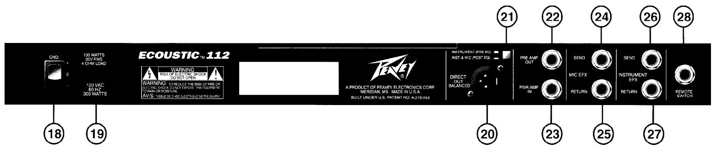
GROUND SWITCH (18)
Three position rocker-type switch, which, in most applications, should be operated in its center or zero position. There may be some situations when audible hum and/or noise will come from the loudspeaker. If this situation arises, position the ground switch to either positive or negative (+ or -) or until the noise is minimized.
Note: Should the noise problem continue, consult your Authorized Peavey Dealer, the Peavey Factory, or a qualified service technician. THE GROUND SWITCH IS NOT FUNCTIONAL ON 220/240 VOLT MODELS.
LINE CORD-I 20 V products only (19)

For your safety, we have incorporated a three-wire line (mains) cable with proper grounding facilities. It is not advisable to remove the ground pin under any circumstances. If it is necessary to use the equipment without proper grounding facilities, suitable grounding adaptors should be used. Less noise and greatly reduced shock hazard exists when the unit is operated with properly grounded receptacles.
DIRECT OUT-LOW-Z BALANCED (20)
An XLR jack is provided to route the signal to mixing/recording consoles.
PRE/POSTEQ SWITCH (21)
Selects either Instrument (Pre EQ) or both the Instrument and Microphone Channel (Post EQ) signals to the direct out jack.
PREAMP OUT (22)
The Preamp Out can be used to route the amplified signal to a mixing console, tape recorder, etc. Connect the Preamp output using a shielded cable to the input of "he tape recorder, mixer, etc. This patch does not affect the operation of the amplifier.
POWER AMP IN (23)
Used to connect line level signal to the power amplifier.
EFFECTS SEND-MIC (24)
Output for supplying signals to external low-level effects or signal processing equipment for the Microphone Channel.
EFFECTS RETURN-MIC (25)
Input for returning signals from external low-level effects or signal processing equipment for the Microphone Channel.
EFFECTS SEND-INSTRUMENT (26)
Output for supplying signals to external low-level effects or signal processing equipment for the Instrument Channel.
EFFECTS RETURN-INSTRUMENT (27)
Input for returning signals from external low-level effects or signal processing equipment for the Instrument Channel. (Footswitchable).
REMOTE SWITCH JACK (28)
Provided for the connection of a 2-button, remote footswitch (optional). The footswitch is used to defeat the effects loop on the Instrument Channel and also allows the user to remotely mute the amplifier.
Note: When the amplifier is muted, the power LED will flash.
IMPORTANT: The mute circuit functions only on the Preamp Out. If the Direct Out is selected to Instrument (Pre EQ), it will not be muted when the amp is muted.
Note: Effects Loop is footswitchable on the Instrument Channel only.
SPECIFICATIONS
Rated Power & Load:
100 W RMS into 4 ohms
Power @ Clipping: (typically)
(1% THD, 1 kHz, 120 V AC line)
100 W RMS into 4 ohms
Frequency Response:
+0, -3 dB, 40 Hz to 20 kHz
@ 80 W RMS into 8 ohms
Hum & Noise:
Greater than 90 dB below rated power
Power Consumption:
Domestic: 300 W @ 60 Hz, 120 V AC
Export: 300 W @ 50/60 Hz, 220-230/240 V AC
PREAMP SECTION
The following specs are measured @ 1 kHz with the controls preset as follo ws:
All equalization sliders @ 0
Feedback frequency @ 40 Hz
Notch @ 0 (full clockwise)
Reverb Sends @ 0
Master Reverb @ 0
Master Presence @ 0
Nominal Levels are with normal volume @ 5
Minimum Levels are with normal volume @ 10
System Hum & Noise @ Nominal Input Level:
(20 Hz to 20 kHz unweighted)
72 dB below rated power
Instrument Input: (passive)
Impedance: High-Z, 2.2 M ohm
Nominal Input Level: -25 dBV, 55 mV RMS
Minimum Input Level: -44 dBV, 6 mV RMS
Maximum Input Level: 0 dBV, 1 V RMS
Instrument Input: (active)
Impedance: High-Z, 44 K ohms
Nominal Input Level: -14 dBV, 200 mV RMS
Minimum Input Level: -32 dBV, 25 mV RMS
Maximum Input Level: 15 dBV, 5.5 V RMS
Microphone Input: (Low-Z balanced)
Impedance: Low-Z, 10 K ohms
Nominal Input Level: -38 dBV, 12 mV RMS
Minimum Input Level: -50 dBV, 3 mV RMS
Maximum Input Level: -6 dBV, 500 V RM
Phantom Powered: /15V
Microphone Input: (High-Z)
Impedance: High-Z, 100 K ohms
Nominal Input Level: -16 dBV, 160mV RMS
Minimum Input Level: -30 dBV, 33 mV RMS
Maximum Input Level: 20 dBV,10 V RMS
Equalization:
Special 5-band active type EQ
Presence: +10dB @ 5 kHz
Feedback Control:
Notch: 20 db
Frequency Range: 40 Hz to 2 kHz
Effects Send:
Load Impedance: 1 K ohm or greater
Nominal Output Level: -10 dBV, 300 mV RMS
Effects Return:
Impedance: High-Z, 22 K ohms
Designed Input Level: -10 dBV, 300 mV RMS
(Switching jack provides Effects Send to Effects Return connection when not used.)
Preamp Output:
Load Impedance: 1 K ohm or greater
Nominal Output Level: 0 dBV, 1 V RMS
Power Amp Input:
Impedance: High-Z, 22 K ohms
Designed Input Level: 0 dBV, 1 V RMS
(Switching jack provides Preamp output to Power Amp input connection when not used.)
Direct Output: (transformer balanced)
Load Impedance: 600 ohms or greater
Nominal Output Level (Post EQ): -3 dBV,
0.7 V RMS
External Footswitch Functions:
Instrument Channel Effects Loop Bypass
Amplifier Mute
Dimensions & Weight:
20.0" H x 23.5" W x 11.25" D
44.9 lbs.

Flowchart
ESPAÑOL
MIC INPUT-LOW-Z (Entree Micro/low-Z) (9)
PRESENCE (Presence) (15)
PEAVEY ELECTRONICS CORPORATION ("PEAVEY") warrants this product, EXCEPT for covers, footswitches, patchcords, tubes and meters, to be free from defects in material and workmanship for a period of one (1) year from date of purchase, PROVIDED, however, that this limited warranty is extended only to the original retail purchaser and is subject to the conditions, exclusions, and limitations hereinafter set forth:
PEAVEY 90-DAY LIMITED WARRANTY ON TUBES AND METERS
If this product contains tubes or meters, Peavey warrants the tubes or meters contained in the product to be free from defects in material and workmanship for a period of ninety (90) days from date of purchase; PROVIDED, however, that this limited warranty is extended only to the original retail purchaser and is also subject to the conditions, exclusions, and limitations hereinafter set forth.
CONDITIONS, EXCLUSIONS, AND LIMITATIONS OF LIMITED WARRANTYES
These limited warranties shall be void and of no effect, if:
a. The first purchase of the product is for the purpose of resale; or
b. The original retail purchase is not made from an AUTHORIZED PEAVEY DEALER; or
c. The product has been damaged by accident or unreasonable use, neglect, improper service or maintenance, or other causes not arising out of defects in material or workmanship; or
d. The serial number affixed to the product is altered, defaced, or removed.
In the event of a defect in material and/or workmanship covered by this limited warranty, Peavey will:
a. In the case of tubes or meters, replace the defective component without charge
b. In other covered cases (i.e., cases involving anything other than covers, footswitches, patchcords, tubes or meters), repair the defect in material or workmanship or replace the product, at Peavey's option; and provided, however, that, in any case, all costs of shipping, if necessary, are paid by you, the purchaser.
THE WARRANTY REGISTRATION CARD SHOULD BE ACCURATELY COMPLETED AND MAILED TO AND RECEIVED BY PEAVEY WITHIN FOURTEEN (14) DAYS FROM THE DATE OF YOUR PURCHASE.
In order to obtain service under these warranties, you must:
a. Bring the defective item to any PEAVEY AUTHORIZED DEALER or AUTHORIZED PEAVEY SERVICE CENTER and present therewith the ORIGINAL PROOF OF PURCHASE supplied to you by the AUTHORIZED PEAVEY DEALER in connection with your purchase from him of this product. If the DEALER or SERVICE CENTER is unable to provide the necessary warranty service you will be directed to the nearest other PEAVEY AUTHORIZED DEALER or AUTHORIZED PEAVEY SERVICE CENTER which can provide such service.
OR
b. Ship the defective item, prepaid, to:
PEAVEY ELECTRONICS CORPORATION
International Service Center
326 Hwy. 11 & 80 East
Meridian, MS 39301
including therewith a complete, detailed description of the problem, together with a legible copy of the original PROOF OF PURCHASE and a complete return address. Upon Peavey's receipt of these items: If the defect is remedial under these limited warranties and the other terms and conditions expressed herein have been complied with, Peavey will provide the necessary warranty service to repair or replace the product and will return it, FREIGHT COLLECT, to you, the purchaser.
Peavey's liability to the purchaser for damages from any cause whatsoever and regardless of the form of action, including negligence, is limited to the actual damages up to the greater of $500.00 or an amount equal to the purchase price of the product that caused the damage or that is the subject of or is directly related to the cause of action. Such purchase price will be that in effect for the specific product when the cause of action arose. This limitation of liability will not apply to claims for personal injury or damage to real property or tangible personal property allegedly caused by Peavey's negligence. Peavey does not assume liability for personal injury or property damage arising out of or caused by a non-Peavey alteration or attachment, nor does Peavey assume any responsibility for damage to interconnected non-Peavey equipment that may result from the normal functioning and maintenance of the Peavey equipment.
UNDER NO CIRCUMSTANCES WILL PEAVEY BE LIABLE FOR ANY LOST PROFITS, LOST SAVINGS, ANY INCIDENTAL DAMAGES, OR ANY CONSEQUENTIAL DAMAGES ASING OUT OF THE USE OR INABILITY TO USE THE PRODUCT, EVEN IF PEAVEY HAS BEEN ADVISED OF THE POSSIBILITY OF SUCH DAMAGES.
THESE LIMITED WARRANTY ARE IN LIEU OF ANY AND ALL WARRANTY, EXPRESSD OR IMplied, INCLUDING, BUT NOT LIMITED TO, THE IMPLIED WARRANTY OF MERCHANTABILITY AND FITNESS FOR A PARTICULAR USE; PROVIDED, HOWEVER, THAT IF THE OTHER TERMS AND CONDITIONS NECESSARY TO THE EXISTENCE OF THE EXPRESSED, LIMITED /WARNTRI ES, AS HEREINABOVE STATED, HAVE BEEN COMPLIED WITH, IMPLIED WARRANTY ARE NOT DISCLAIMED DURING THE APPLICABLE ONE-YEAR OR NINETY-DAY PERIOD FROM DATE OF PURCHASE OF THIS PRODUCT.
SOME STATES DO NOT ALLOW LIMITATION ON HOW LONG AN IMPLIED WARRANTY LASTS, OR THE EXCLUSION OR LIMITATION OF INCIDENTAL OR CONSEQUENTIAL DAMAGES, SO THE ABOVE LIMITATIONS OR EXCLUSIONS MAY NOT APPLY TO YOU. THESE LIMITED WARRANTY SUE给你们 SPECIFIC LEGAL RIGHTS, AND YOU MAY ALSO HAVE OTHER RIGHTS WHICH MAY VARY FROM STATE TO STATE.
THESE LIMITED WARRANTY ARE THE ONLY EXPRESSED WARRANTY ON THIS PRODUCT, AND NO OTHER STATEMENT, REPRESENTATION, WARRANTY, OR AGREEMENT BY ANY PERSON SHALL BE VALID OR BINDING UPON PEAVEY.
In the event of any modification or disclaimer of expressed or implied warranties, or any limitation of remedies, contained herein conflicts with applicable law, then such modification, disclaimer or limitation, as the case may be, shall be deemed to be modified to the extent necessary to comply with such law.
Your remedies for breach of these warranties are limited to those remedies provided herein and Peavey Electronics Corporation gives this limited warranty only with respect to equipment purchased in the United States of America.
INSTRUCTIONS-WARRANTY REGISTRATION CARD
- Mail the completed WARRANTY REGISTRATION CARD to:
PEAVEY ELECTRONICS CORPORATION
P.O. BOX 2898
Meridian, MS 39302-2898
a. Keep the PROOF OF PURCHASE. In the event warranty service is required during the warranty period, you will need this document. There will be no identification card issued by Peavey Electronics Corporation.
2. IMPORTANCE OF WARRANTY REGISTRATION CARDS AND NOTIFICATION OF CHANGES OF ADDRESSES:
a. Completion and mailing of WARRANTY REGISTRATION CARDS — Should notification become necessary for any condition that may require correction, the REGISTRATION CARD will help ensure that you are contacted and properly notified.
b. Notice of address changes - If you move from the address shown on the WARRANTY REGISTRATION CARD, you should notify Peavey of the change of address so as to facilitate your receipt of any bulletins or other forms of notification which may become necessary in connection with any condition that may require dissemination of information or correction.
3. You may contact Peavey directly by telephoning (601) 483-5365.
IMPORTANT SAFETY INSTRUCTIONS
WARNING: When using electric products, basic cautions should always be followed, including the following:
- Read all safety and operating instructions before using this product.
- All safety and operating instructions should be retained for future reference.
- Obey all cautions in the operating instructions and on the back of the unit.
- All operating instructions should be followed.
- This product should not be used near water, i.e., a bathtub, sink, swimming pool, wet basement, etc.
- This product should be located so that its position does not interfere with its proper ventilation. It should not be placed flat against a wall or placed in a built-in enclosure that will impede the flow of cooling air.
- This product should not be placed near a source of heat such as a stove, radiator, or another heat producing amplifier.
- Connect only to a power supply of the type marked on the unit adjacent to the power supply cord.
- Never break off the ground pin on the power supply cord. For more information on grounding, write for our free booklet "Shock Hazard and Grounding."
- Power supply cords should always be handled carefully. Never walk or place equipment on power supply cords. Periodically check cords for cuts or signs of stress, especially at the plug and the point where the cord exits the unit.
- The power supply cord should be unplugged when the unit is to be unused for long periods of time.
- If this product is to be mounted in an equipment rack, rear support should be provided.
- Metal parts can be cleaned with a damp rag. The vinyl covering used on some units can be cleaned with a damp rag or an ammonia-based household cleaner if necessary. Disconnect unit from power supply before cleaning.
- Care should be taken so that objects do not fall and liquids are not spilled into the unit through the ventilation holes or any other openings.
- This unit should be checked by a qualified service technician if:
a. The power supply cord or plug has been damaged.
b. Anything has fallen or been spilled into the unit.
c. The unit does not operate correctly.
d. The unit has been dropped or the enclosure damaged.
- The user should not attempt to service this equipment. All service work should be done by a qualified service technician.
- This product should be used only with a cart or stand that is recommended by Peavey Electronics.
- Exposure to extremely high noise levels may cause a permanent hearing loss. Individuals vary considerably in susceptibility to noise induced hearing loss, but nearly everyone will lose some hearing if exposed to sufficiently intense noise for a sufficient time. The U.S. Government's Occupational Safety and Health Administration (OSHA) has specified the following permissible noise level exposures.
| Duration Per Day In Hours | Sound Level dBA, Slow Response |
| 8 | 90 |
| 6 | 92 |
| 4 | 95 |
| 3 | 97 |
| 2 | 100 |
| 1 1/2 | 102 |
| | | 105 |
| 1/2 | 110 |
| 1/4 or less | 115 |
According to OSHA, any exposure in excess of the above permissible limits could result in some hearing loss.
Ear plugs or protectors in the ear canals or over the ears must be worn when operating this amplification system in order to prevent a permanent hearing loss if exposure is in excess of the limits as set forth above. To ensure against potentially dangerous exposure to high sound pressure levels, it is recommended that all persons exposed to equipment capable of producing high sound pressure levels such as this amplification system be protected by hearing protectors while this unit is in operation.
SAVE THESE INSTRUCTIONS!

Features and specifications subject to change without notice.

- FRONT PANEL FEATURES
- INPUT (1)
- PASSIVE/ACTIVE SWITCH (2)
- PHASE REVERSE SWITCH (3)
- INSTRUMENT LEVEL (4)
- EQUALIZATION—INSTRUMENT CHANNEL (5)
- FREQUENCY (6)
- NOTCH (7)
- REVERB SEND-INSTRUMENT CHANNEL (8)
- MIC INPUT/LOW-Z (9)
- MIC INPUT/HIGH-Z (10)
- MIC LEVEL (11)
- EQUALIZATION-MIC CHANNEL (12)
- REVERB SEND-MIC CHANNEL (13)
- MASTER REVERB (14)
- PRESENCE (15)
- POWER LED (16)
- POWER SWITCH (17)
- BACK PANEL
- BACK PANEL FEATURES
- GROUND SWITCH (18)
- LINE CORD-I 20 V PRODUCTS ONLY (19)
- DIRECT OUT-LOW-Z BALANCED (20)
- PRE/POSTEQ SWITCH (21)
- PREAMP OUT (22)
- POWER AMP IN (23)
- EFFECTS SEND-MIC (24)
- EFFECTS RETURN-MIC (25)
- EFFECTS SEND-INSTRUMENT (26)
- EFFECTS RETURN-INSTRUMENT (27)
- REMOTE SWITCH JACK (28)
- SPECIFICATIONS
- ESPAÑOL
- MIC INPUT-LOW-Z (ENTREE MICRO/LOW-Z) (9)
- PRESENCE (PRESENCE) (15)
- PEAVEY 90-DAY LIMITED WARRANTY ON TUBES AND METERS
- CONDITIONS, EXCLUSIONS, AND LIMITATIONS OF LIMITED WARRANTYES
- OR
- PEAVEY ELECTRONICS CORPORATION
- INSTRUCTIONS-WARRANTY REGISTRATION CARD
- IMPORTANT SAFETY INSTRUCTIONS
- SAVE THESE INSTRUCTIONS
Brand : PEAVEY
Model : ECOUSTIC 112
Category : Acoustic amplifier