
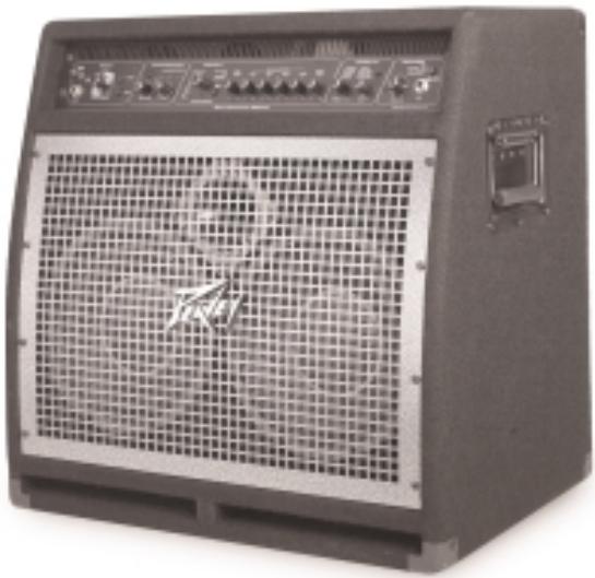
BAM 210 - Bass Amplifier PEAVEY - Free user manual and instructions
Find the device manual for free BAM 210 PEAVEY in PDF.

| Product Type | Bass guitar combo amplifier |
| Output Power | 500 W RMS into 2 ohms, 350 W RMS into 4 ohms |
| Speakers | 2 x 10" (cast-frame) + 1 compression horn |
| Minimum Load Impedance | 2 ohms |
| Amp Modeling | 8 models (RED, 360, TVS, FLIPTOP, B-MAN, PEAVEY MAX, WEST COAST, FREDDIE K) |
| Cabinet Modeling | 8 configurations (2x10, 1x18, 8x10, 1x15, 2x12, BAM 2x10, 4x10, ALLOY 4x10) |
| Digital Effects | 8 effects (Chorus, Synth bass, Flange, Fretless bass, Phase shift, Funk wah, Octave divider, Distortion) |
| Built-in Compressor | Yes, soft-knee type with Squeeze and Level controls |
| Presets | 16 factory presets + 16 user presets |
| Equalization | Variable per amp model (active/passive, semi-parametric mid with Shift) |
| Inputs | 1 x 1/4" TS high-impedance input (INPUT), 1 x 1/4" POWER AMP IN |
| Outputs | 1 x balanced XLR (XLR OUTPUT with adjustable level and Pre/Post EQ), 1 x 1/4" PREAMP OUT, 1 x 1/4" headphone jack (HEADPHONE) |
| Effects Loop | Usable via PREAMP OUT / POWER AMP IN |
| MIDI | MIDI IN/FOOTSWITCH (8-pin), MIDI OUT (5-pin); configurable MIDI channel |
| Included Footswitch | PFC™4B (4 modes: Preset, Bank Select, EFX Select, Tuner) |
| Built-in Tuner | Chromatic and diatomic for 4, 5, or 6-string bass; Eb tuning possible |
| DDT™ Protection | Anti-clipping power compression with LED indicator and bypass |
| External Speaker | 1/4" jack output for additional speaker (4 ohms minimum) |
| Power Supply | 220-240 V~50/60 Hz (export model); grounded IEC socket; resettable circuit breaker |
| Dimensions (approx.) | Height: 55 cm, Width: 60 cm, Depth: 45 cm (estimate) |
| Weight (approx.) | Approximately 25 kg (estimate) |
| Maintenance and Cleaning | Unplug before cleaning; use a dry cloth; do not expose to moisture |
| Safety | Do not open, do not expose to rain or moisture; refer servicing to qualified Peavey service personnel |
| Spare Parts and Repairability | Contact an authorized Peavey dealer; user-resettable circuit breaker |
Frequently Asked Questions - BAM 210 PEAVEY
User questions about BAM 210 PEAVEY
0 question about this device. Answer the ones you know or ask your own.
Ask a new question about this device
Download the instructions for your Bass Amplifier in PDF format for free! Find your manual BAM 210 - PEAVEY and take your electronic device back in hand. On this page are published all the documents necessary for the use of your device. BAM 210 by PEAVEY.
USER MANUAL BAM 210 PEAVEY
BAM 210 Operation Manual

natural_image
Black and white photo of a black audio amplifier front panel with grid grille and control knobs (no visible text or symbols)

Intended to alert the user to the presence of uninsulated “dangerous voltage” within the product’s enclosure that may be of sufficient magnitude to constitute a risk of electric shock to persons.

Intended to alert the user of the presence of important operating and maintenance (servicing) instructions in the literature accompanying the product.
CAUTION: Risk of electrical shock — DO NOT OPEN!
CAUTION: To reduce the risk of electric shock, do not remove cover. No user serviceable parts inside. Refer servicing to qualified service personnel.
WARNING: To prevent electrical shock or fire hazard, do not expose this appliance to rain or moisture. Before using this appliance, read the operating guide for further warnings.

Do you think achieving a virtually unlimited collection of bass amp and cabinet tones out of a compact 2 x 10 combo is impossible? Not with the BAM 210 from Peavey Electronics. Years of research and development have produced a feature-packed bass modeling amp engineered to please today's discriminating bassist and those who listen to the music. From its user-friendly interface to its 1/4" and XLR external outputs, the BAM is the amplifier that will take bass sound into the new millennium.
natural_image
Front view of a gray industrial control unit with grid and indicator lights (no visible text or symbols)FEATURES
• 500 W @ 2 Ohms, 350 W @ 4 Ohms
- 2 x 10" cast-frame woofers
• 1x compression horn
- Front ported
- Angled baffle board (for that tilt-back sound without sacrificing low end)
- Analog compressor
- 8 digital effects
- Chorus - Synth bass
- Flange - Fretless bass
- Phase shift - Funk wah
- Octave divider - Distortion
- 8 amp models that include active and passive tone models
PRESET STRUCTURE
The BAM 210 is shipped with 16 factory presets and 16 user presets. The user presets are identical to the factory presets until modified. The factory presets illustrate the amplifier's capabilities, and can be altered and stored as user presets. Turning the unit on while simultaneously pressing both the USER and STORE buttons on the amplifier front panel will revert both factory and user presets to their original settings. Known as reinitializing, this procedure should be performed when the unit is first unpacked and hooked up to delete any alterations to the presets that may have been made
prior to your purchase. If you become dissatisfied with your user presets at any time, reinitialization will return all user presets to the factory settings.
Suppose you like factory setting A 1 but desire more low frequency response. Press the USER button on the front panel. Since the unit has been reinitialized, user preset A 1 is the same as factory preset A 1. Now simply adjust the low frequency to your liking and press STORE twice. The increased low-frequency setting will be called up whenever user preset A 1 is selected. If a factory preset is changed and not stored as a user preset, it will revert back to the factory setting once the next preset is selected.
Both the factory and user presets are stored in the PRESET MATRIX. This matrix is divided into 4 banks (A, B, C, D), with each bank containing 4 presets (1, 2, 3, 4). Selection between factory and user presets is accomplished with the USER switch. Storage location within the matrix is selected using the STORE switch. Detailed description of the matrix and its controls is included in the following section.
FEATURES AND CONTROLS
FRONT PANEL
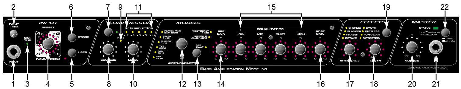
text_image
INPUT TRIM S1 SIG. CHP INPUT PRESET A 3 4 5 B D 2 3 4 5 C MATRIX STORE USER COMPRESSOR GAIN REDUCTION -12 -9 -6 -3 -1 CMP SQUETZE LEVEL 10 11 15 19 22 BASS AMPLIFICATION MODELING MODELS PRAVEY MAX GAN 2X10 S-MAN 2X10 FROOD X ALLOY 4X10 FREDUCE X CAR SWAP AMPS/CABINETS PRE GAIN LOW MID SHIFT HIGH POST GAIN EQUALIZATION EFFECTS CHORUS SYNTH FLANGER FRETLESS PHASER FUNK WAH OCTAVE DISTORTION SPEAK/ADJ ORTH MASTER STATUS DOT™ SPEAKER PROTECTION CREAT ENABLE DESIGNED AND MADE IN USA. 1 2 3 4 5 6 7 8 9 10 11 12 13 14 15 16 17 18 19 20 21(1) INPUT
This 1/4" mono (TS) jack is a high-impedance input designed to handle a broad range of bass pickup signals, both active and passive.
(2) INPUT TRIM
This control adjusts the level of the signal entering the INPUT (1). Instruments with high output levels may have to be “trimmed” down to avoid overdriving (distorting) the INPUT.
(3) SIG/CLIP
This 2-color LED indicates signal presence as well as warning of clipping the INPUT (1). Green illumination will occur in response to signal presence at the INPUT, while red illumination warns of potential clipping. Excessive red illumination indicates a need to adjust the INPUT TRIM (2).
(4) PRESET MATRIX
This control, along with the USER (5) switch, allows selection among the 32 available presets. The matrix is divided into 4 banks (A, B, C, D), with each bank containing 4 presets (1, 2, 3, 4). Depending on the position of the USER switch, the PRESET MATRIX selector allows selection of the 16 factory presets or the 16 user presets. The active preset is indicated by LED illumination. Presets can also be selected via the foot controller or by MIDI command.
(5) USER
This control determines whether the presets available at the PRESET MATRIX (4) selector (4) are factory settings or user settings. The adjacent yellow LED will illuminate when the user presets are active.
(6) STORE
This control allows the storage of presets in specific locations. When a preset has been finalized and is ready for storage, press this switch once. The LED indicating the current storage location will begin to flash. If the storage location is to remain the same, press the switch again and the function is complete. If a new location is desired, turn the PRESET MATRIX selector to the desired location. When the LED indicating the new location begins to flash, press the switch again. The preset is now in its new position within the matrix.
NOTE: Factory presets must be stored to a User location when altered. If not, they will revert to their original settings when another preset is selected.
(7) COMPRESSOR
This control selects or bypasses the BAM's onboard compressor. The adjacent green LED indicates compressor activation.
(8) SQUEEZE
Since the BAM's compressor is “soft knee,” this control functions as a combination ratio and threshold control. Rotating the control clockwise decreases the threshold (the level at which compression activates), while increasing the ratio (the amount of compression). A compression ratio expresses the input level versus the output level. For example, a 4 to 1 ratio means that for a 4 dB change in input level there is a 1 dB change in output level. A “soft knee” compressor delivers a lower ratio for low-level signals and a higher ratio for high-level signals.
(9) CLIP LED
This red LED samples the output of the compressor and warns of potential clipping. Illumination indicates a need to reduce the LEVEL (10) control.
(10) LEVEL
This control sets the compressor output level and allows recovery of gain lost by compression, also known as make-up gain.
(11) GAIN REDUCTION LEDs
These indicators show the amount of gain reduction due to compression.
(12) MODEL SELECTOR
This control, in conjunction with the CAB SWAP (13) switch, allows selection among the BAM's amplifier and speaker cabinet models. LED illumination indicates which model is active (red = amp model; green = cabinet model; orange = amp and cab model overlayed). If storage of a particular model is desired, press the STORE (6) switch to store that model in the current preset location. See the chart on page 6 for a description of amplifier characteristics.
(13) CAB SWAP
This control allows speaker cabinet models to be changed. Once the desired amp model has
been selected via the MODEL SELECTOR (12) control, pressing this button allows the user to change cabinets without altering the amplifier selection. For example, the current model is B-MAN 2X12. To hear this amp through a 1X15, press the CAB SWAP button. The adjacent green LED will illuminate to indicate Cab Swap mode. Rotate the MODEL SELECTOR switch to the FLIPTOP 1X15 setting. The sound is now B-MAN 1X15 (amp model B-MAN; cab model 1X15). See the chart below for a description of cabinet characteristics.
| Amp Model | Cabinet Model | Description |
| RED | 2 X 10 | Modern 2 X 10 combo amp with active semi-parametric EQ. Front ported cab with horn. |
| 360 | 1 X 18 | Old solid state head with passive EQ. Single 18 inch folded horn cab. |
| TVS | 8 X 10 | Vintage all tube head with passive EQ. Sealed 8 X 10 cab with no horn. |
| FLIPTOP | 1 X 15 | Vintage all tube portable bass combo with passive EQ. 1 X 15 cab. |
| B-MAN | 2 X 12 | Classic all tube bass head with 3-band passive EQ. Closed back 2 X 12 cab. |
| PEAVEY MAX | BAM 2 X 10 | Hybrid bass preamp with active 3-band semi-parametric EQ. BAM cab with no modeling. |
| WEST COAST | 4 X 10 | Modern hybrid bass head with active semi-parametric EQ. Modern front ported 4 X 10 with horn. |
| FREDDIE K | ALLOY 4 X 10 | Modern solid state head with active 4-band EQ. Metal cone speakers in ported 4 X 10 with no tweeter. |
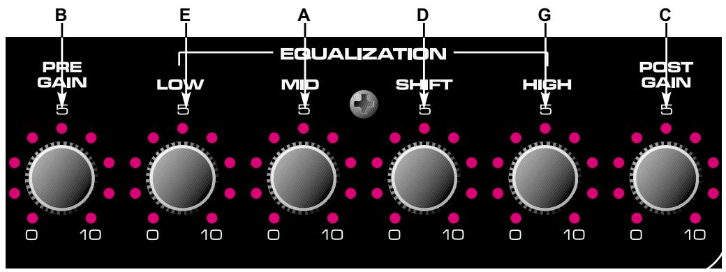
(14) PRE GAIN
This control sets the BAM's preamp gain when the amp model has a pre-gain function associated with it. Rotating the control clockwise increases gain. The setting of this control will modify a preset, and the new setting can be saved as a user preset. If the LEDs surrounding this control do not illuminate, the amp model has no pre-gain function. Pre gain function can be added (or removed) in tweaks. See the TWEAK / TUNER POWER FEATURES section of this manual for tweak instructions.
(15) EQUALIZATION
The EQ on the BAM 210 allows adjustment of the amp model selected. Each of the models emulated has differences in EQ circuitry, whether it be active or passive, or just a different center frequency or bandwidth. Since the EQ on the BAM simulates the EQ on the amp it is modeling, adjusting the controls in this section is like adjusting the controls on the amp being modeled. Regardless of the amp, rotating the LOW control clockwise boosts the low frequencies; the MID control the mid frequencies; and the HIGH control the high frequencies. For amps with a shiftable mid-range, the SHIFT control moves the mid-range center frequency.
(16) POST GAIN
This control sets the overall volume for a preset. As with the PRE GAIN (14), rotating the control clockwise increases gain, and the new setting can be stored as a user preset.
These controls set the parameters of the effect selected via the EFFECTS SWITCH (19). Refer to the TWEAK / TUNER POWER FEATURES section of this manual for an explanation of the function of these controls. The parameters of an effect can be toggled between two settings by using the footswitch in the EFX SELECT mode. When toggling between settings, both parameters are changed simultaneously.
(19) EFFECTS
This control selects the effect that is active. The yellow LEDs adjacent to the effect names indicate which one is active.
(20) MASTER VOLUME
This control sets the overall volume level of the BAM. This control is independent of stored presets and can be used to adjust the output volume level to accommodate different playing situations.
(21) HEADPHONE JACK
This 1/4" stereo (TRS) jack accepts standard stereo headphones only. Using this jack interrupts the signal to the speakers, making it ideal for quiet practice situations. Although it is a stereo connector, the signal sent to it is mono and the sound heard in both sides of the phones will be the same.
(22) DDT ^TM SELECTOR
This switch controls Peavey's exclusive DDT™ (Distortion Detection Technique) speaker protection. With this switch in the OUT position, a unique circuit senses signal conditions that might overload the amplifier and activates compression to reduce gain and avoid clipping. This technique utilizes every Watt available for the amplifier to reproduce the signal, yet minimizes clipping and distortion which reduces the potential of speaker damage. This circuitry is independent of the amplifier compression section. Since this function is “invisible” at levels below the clipping point, it is advised that it be activated at all times. Setting this switch to the “IN” position defeats this protection feature, allowing potential power amp clipping and the resultant increase in likelihood of speaker damage.
BACK PANEL
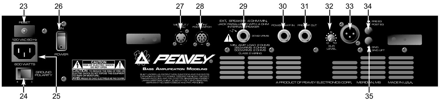
text_image
23 120 VAC 60 Hz 600 WATTS GROUND POLARITY 24 25 26 POWER CAUTION RISK OF ELECTRIC SHOCK DO NOT OPEN AVIS: INSQUE DE CHOC ELECTRIQUE ARE PAS OLVERS 27 MIN. OUT/ TREU MIN. IN/ FOOT SWITCH EXT. SPEAKER 4 OHM MIN. JACK PARALLEL WITH 4 OHM INTERNAL SPEAKER 3742 VRMS MIN. AMP LOAD 2 OHMS 500WARS 4 OHMS 500WARS 5 OHMS CLASS 2 VRMS 29 POWER/MP IN PREMP OUT XLR LEVEL 30 31 32 33 34 FREEG POST EG GND GND UFT PEAVEY® BASS AMPLIFICATION MODELING A PRODUCT OF PEAVEY ELECTRONICS CORP. MERIDIAN, MS MADE IN USA.(23) CIRCUIT BREAKER RESET

This button resets the internal circuit breaker. Under normal operating conditions, the breaker should not trip. Conditions such as a short circuit or continuous operation at overload or clipping may cause this breaker to trip. In the event this occurs, turn off power to the unit and wait 60 seconds before pressing this button to reset the breaker. Efforts should be made to determine the cause of the overload. If the breaker continues to trip, the unit should be taken to a qualified Peavey Service Center for repair.
(24) GROUND POLARITY
This 3-position, rocker-type switch should normally be placed in the center (0) position. If hum or noise is noticed coming from the speaker enclosure(s), the switch may be placed in the (+) or (-) position to minimize hum/noise. If changing the polarity does not alleviate the problem, consult your authorized Peavey dealer, the Peavey factory, or a qualified service technician.
(25) IEC MAINS CONNECTOR
This is a standard IEC power connector. An AC mains cord having the appropriate AC plug and ratings for the intended operating voltage is included in the carton. The mains cord should be connected to the amplifier before connecting to a suitable AC outlet.

U.S DOMESTIC AC MAINS CORD
The mains cord supplied with the unit is a heavy-duty, 3-conductor type with a conventional 120 VAC plug with ground pin. If the outlet used does not have a ground pin, a suitable grounding adapter should be used and the third wire should be grounded properly.
Never break off the ground pin on any equipment. It is provided for your safety.
NOTE: FOR UK ONLY
If the colors of the wires in the mains lead of this unit do not correspond with the colored markings identifying the terminals in your plug, proceed as follows: (1) The wire that is colored green and yellow must be connected to the terminal that is marked by the letter E, the earth symbol, colored green, or colored green and yellow. (2) The wire that is colored blue must be connected to the terminal that is marked with the letter N or the color black. (3) The wire that is colored brown must be connected to the terminal that is marked with the letter L or the color red.
(26) POWER SWITCH
This two-way toggle switch applies mains power to the unit when placed in the ON position.
(27) MIDI OUT / THRU
This standard 5-pin DIN sends MIDI program changes out and/or thru the BAM ^™ 210. Refer to the FOOTSWITCH / MIDI section of this manual for more information.
(28) MIDI IN / FOOTSWITCH
This 8-pin DIN is receives MIDI commands from an external controller. It will accept both standard 5-pin DIN cables as well as Peavey's 8-pin MIDI/Communication combo cable. The 8-pin cable provides connection and power to the footswitch (supplied). Refer to the FOOTSWITCH / MIDI section of this manual for more information.
(29) EXTERNAL SPEAKER JACK
This 1/4" mono (TS) jack allows the connection of an external speaker cabinet(s). The jack is wired in parallel with the internal speakers. Minimum external enclosure impedance is 4 Ohms.
(30) POWER AMP IN
This 1/4" jack allows the connection of line level signals directly to the power amp.
(31) PREAMP OUT
This 1/4" jack allows patching to mixing consoles, tape recorders, etc. Use a shielded cable to patch from this jack to the input of the device receiving the signal. This patch does not affect the operation of the amplifier or the signal continuing to the power amp and speakers.
NOTE: The PREAMP OUT / POWER AMP IN jacks can also be used to patch line level effects units.
(32) XLR LEVEL
This control sets the signal level being sent out the XLR OUTPUT (33). Clockwise rotation increases the level of the signal being sent; counterclockwise rotation decreases the level.
(33) XLR OUTPUT
This low-noise, electronically balanced XLR (3-pin) connector allows low-impedance patches to be made from the amplifier. Connector wiring is: Pin 1 = Ground; Pin 2 = Positive; Pin 3 = Negative.
(34) PRE / POST EQ
This switch determines whether the signal being sent from the XLR OUTPUT (33) is pre or post-EQ, meaning whether or not that signal is affected by the EQ section of the amp. The OUT position is pre-EQ (not affected), while the IN position is post-EQ (affected), including all modeling, compression and effects.
(35) GND / GND LIFT
This switch lifts the ground from Pin 1 of the XLR connector to prevent a possible ground loop if the amplifier is connected to another piece of equipment, a mixing board for example, that is on another electrical circuit.
TUNER
The BAM's tuner accommodates 4, 5, or 6-string basses in standard tuning formats as well as functioning chromatically. The Tuner can be accessed by pressing the USER (5) and STORE (6) buttons simultaneously, or via the footswitch. (See Tuner Mode in the FOOTSWITCH section of this manual.) The default mode for the tuner is standard bass tuning (B E A D G C), and the Tuner will be in this mode when selected. To enter the chromatic mode, press the COMPRESSOR (7) button while in Tuner Mode. The LED adjacent to the COMPRESSOR will illuminate when the tuner is in the chromatic mode. The LED displays for controls 14 –16 function as strobe-style indicators relative to the note they are tracking. (See the diagram below.) Counterclockwise rotation indicates that the note being tracked is flat; clockwise rotation indicates the note is sharp. The speed of rotation will
decrease as the note comes closer to tune, and rotation will stop when the note reaches correct pitch. The LEDs for the SPEED/ADJ (17) control show a more standard tuning display where the 12 o'clock position illuminates when the note is in tune. The DEPTH (18) control sets tuner volume in this mode.
In the Bass mode, the tuner searches for standard bass notes and automatically selects the closest standard tuning note in relation to the note being played. In the Chromatic mode, the tuner tracks all notes, whether they are standard or not. For example, if an F note were played it would be tracked as such, lighting up both the E and G LED displays since F is between E and G. The BAM's tuner also allows Eb tuning. To enter this mode, press the USER (5) button while in the Tuner mode. Tuner settings can be saved by pressing the STORE (6) button.
flowchart
graph TD
    A["PRE GAIN"] --> B["0 10"]
    C["LOW"] --> D["0 10"]
    E["EQUALIZATION"] --> F["0 10"]
    G["DSHIFT"] --> H["0 10"]
    I["GICHT"] --> J["0 10"]
    K["POST GAIN"] --> L["0 10"]
FOOTSWITCH
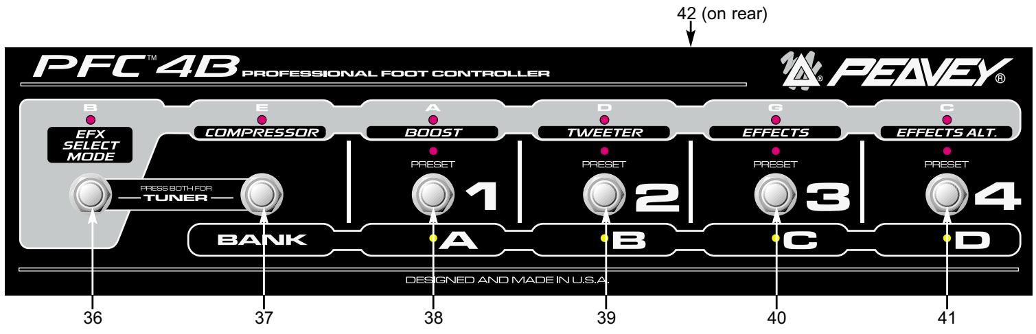
The PFC ^™ 4B operates in four different modes: Preset, Bank Select, EFX Select, and Tuner. The buttons on the footswitch perform different functions based on the active mode. Mode selection is accomplished via the EFX SELECT MODE (36) and BANK (37) buttons. The function of each button in the various modes is described by mode in the section below the diagram. If a particular button is not listed, it has no function in that mode.
flowchart
graph LR
    A["PFCTM 4B PROFESSIONAL FOOT CONTROLLER"] --> B["EFX SELECT MODE"]
    B --> C["BANK"]
    C --> D["COMPRESSOR"]
    D --> E["A BOOST"]
    E --> F["PRESET 1"]
    F --> G["TWEETER"]
    G --> H["D EFFECTS"]
    H --> I["G EFFECTS ALT."]
    I --> J["C EFFECTS ALT."]
    J --> K["D EFFECTS ALT."]
    style A fill:#f9f,stroke:#333
    style B fill:#ccf,stroke:#333
    style C fill:#cfc,stroke:#333
    style D fill:#fcc,stroke:#333
    style E fill:#cff,stroke:#333
    style F fill:#ffc,stroke:#333
    style G fill:#cfc,stroke:#333
    style H fill:#fcc,stroke:#333
    style I fill:#cfc,stroke:#333
    style J fill:#fcc,stroke:#333
    style K fill:#cfc,stroke:#333
PRESET MODE
This mode is the default setting. When the amplifier is powered up, the footswitch will be in this mode. Selection of individual presets within the current bank can be accomplished in this mode. The active bank is indicated by illumination of the corresponding yellow LED (A, B, C, D). The current preset within the bank is indicated by illumination of the corresponding red LED (1, 2, 3, 4). Buttons 38 - 41 change the preset. The green EFX Mode LEDs will light dimly in this mode if their function is enabled.
BANK SELECT MODE
Pressing button 37 when in Preset Mode selects Bank Select Mode. The corresponding yellow LED (A, B, C, D) will blink as an indication of the active bank upon entering this mode. Buttons 38 - 41 change the active bank. The LED will illuminate continuously when a bank is selected. Pressing button 37 again returns to the Preset Mode.
EFX SELECT MODE
Pressing button 36 selects this mode. The corresponding green LED will illuminate when this mode is selected. Buttons 37 - 41 function as follows:
37 – Compressor on/off
38 - Toggles between primary and secondary settings for controls 14 - 16.
39 – Tweeter on/off
40 – Effects on/off
41 - Toggles between primary and secondary settings for effects.
SETTING THE BOOST/EFFECTS LEVELS
There are eight parameter knobs from Pre Gain though Effects Depth. Each one has dual settings saved with each preset. The PFC ^™ 4B footswitch lets you toggle between these primary and secondary settings when in EFX mode, as follows:
BOOST - toggles all six preamp parameters: Pre Gain, Low, Mid, Shift, High, Post Gain EFFECTS ALT - toggles the effect's Speed/Adj and Depth parameters
The boost function lets you have a completely different preamp setting for solos, etc. Not only can you boost or cut pre and post gain, you can also dip your mids and boost your highs, etc. The dual settings for the effects mean that the PFC4B can do more than just turn them on and off. “Off” isn’t always one of the top two choices, so why lock it in? Do things like:
- Have lots of phaser when the PFC4B's Effects Alt LED is on, and just a little bit when it's off.
- Switch between low and high speeds on the flanger.
- Kick in extra distortion in parallel with the dry sound to fill the mids when the guitarist solos.
This setup makes for some fun preset building!
SETTING AND STORING THE BOOST/EFFECTS LEVELS
Here's the easy part. Turn the boost off on the PFC4B and set your non-boost tone and level (primary settings). Turn the boost on and set your boost tone and level (secondary settings, see page 12 for sync power tip!) Then do the same for the effects. Once you have them all working the way you want, set the EFX functions on the PFC4B to how you want them when the preset is recalled (e.g. boost off, etc.), then store the preset. (You only have to do the store function once. The primary and secondary settings are all in the same preset, so you won't lose primaries by switching to secondaries, etc.)
TUNER MODE
Pressing buttons 36 & 37 simultaneously selects the tuner mode. The four yellow LEDs will illuminate dimly as an indication that the Tuner Mode is active and awaiting a signal. Pressing any button will exit the Tuner Mode and return to the previous mode and preset.
The green LEDs indicate the note the tuner is tracking. In the chromatic mode the two LEDs that a note falls between will light if the note being tracked is not a note in standard bass tuning.
Once a note is being tracked, the yellow and red LEDs function similarly to a strobe tuner, that is they light sequentially to form a ring. Counterclockwise movement of the ring indicates the note being tracked is flat; clockwise movement indicates it is sharp. The rotation speed will decrease as the note comes closer to tune, and all indicators will illuminate (no movement) when the note reaches correct pitch.
(42) REMOTE CABLE CONNECTOR
This 8-pin DIN connector transmits and receives MIDI commands to and from the MIDI IN / FOOTSWITCH (28). Certain functions, such as the tuner, are also communicated through this connection. Only the Peavey 8-pin MIDI/Communication cable (included) should be used for this connection.
HIDDEN POWER FEATURES
The BAM lets you do most of what you need via the standard controls on the front panel and footswitch. However, there are other parameters under the hood that you can get to if you're willing to dig a little deeper. By holding the USER button for more than a second (and continuing to hold), you can access additional preset parameters. Doing the same with the STORE button accesses global preference parameters. The following table and subsequent text shows what parameters are available.
TWEAK / TUNER POWER FEATURES
| Control | Preset Tweak(hold USER for 1 sec.) | Global Tweak(hold STORE for 1 sec.) | Tuner Tweak(Press STORE and USER) |
| Preset | - | MIDI Channel | [Exit Tuner] |
| Store | - | - | Store Tuner Tweaks |
| User | - | User on Powerup | Eb mode |
| Compressor | - | - | Chromatic Mode |
| Model | - | - | [Exit Tuner] |
| Cab Swap | - | - | [Exit Tuner] |
| Pre | Analog Overdrive Enable | - | - |
| Bass | - | - | - |
| Mid | - | - | - |
| Shift | - | - | - |
| Treble | Tweeter Enable | Footswitch All-Info | - |
| Post | - | Bank Select Style | - |
| Effect Select | - | - | [Exit Tuner] |
| Speed/Adj | Tweak 1 | Noise Gate Sensitivity | - |
| Depth | Tweak 2 | Noise Gate Threshold | Tuner Volume |
POWER TIP! BOOST/FX SETTINGS COPYING
The boost function allows you to have two complete settings (per preset) for the pre gain, post gain, and three-band EQ. When creating a preset, you will typically build your non-boost sound (boost LED off on the PFC4B), then want to modify it for the boost. Well, the settings will usually be very different, and synchronizing them manually is a bit of a pain. So, you can press the USER button for one second (and continue to hold, which puts the amp into Patch Tweak mode, see below), and hit the boost footswitch. This will copy the five parameters from the non-boost to the boost slots. (If you were boosted in the first place, the copy would go the other way - it goes from where you were to where you're switching.) This also works with the effects knobs, but since there are only two, it's not much of a problem to tweak them manually.
DETAILS
PRESET:
- Analog Overdrive Enable - Enabled or disabled by amp model selection, after which this can override.
- Tweeter Enable - Enabled or disabled by cabinet model selection, after which this can override.
- Tweak 1 & 2 - See table below.
GLOBAL:
- MIDI Channel - Goes from 1 (matrix LED A1) to 16 (matrix LED D4). Footswitch / Sysex will always work. Channel messages will be sent with this channel, and will be ignored upon receive unless on this channel. (default = 1)
- User on Powerup - Default is factory presets on powerup - LED off. Turn on for USER presets on powerup.
• Footswitch All-Info will be:
• 0 = Only shows LEDs of current mode (either greens or reds/yellows). Less info, less confusing. [7:00/min]
• 1 = (default) Shows dim LEDs for the inactive mode (e.g. greens when NOT in EFX mode). [12:00]
• 2 = Shows all LEDs bright in either mode. Good for seeing everything in brighter light where the dim level could wash out. [5:00/max]
• Bank Select Style will be
• 0 = (default) go to same preset in new bank [7:00/min]
• 1 = go to preset #1 in new bank [12:00]
• 2 = wait for user to press a preset footswitch before switching (current red blinks) [5:00/max]
- Noise Gate Sensitivity - Increase this to get more gating effect. Reduce to get a gentle reduction. (default = 9:00)
- Noise Gate Threshold - Set this while the bass volume is up but the strings are muted. Turn Sensitivity up all the way, then turn this up until you hear the noise drop out. Then go up just a bit more (one or two LED changes). Then reduce the Sensitivity to taste. (default = off)
TUNER:
- Store Tuner Tweaks - Tuner will not remember your preferences unless you save them (just press once).
- Eb mode - Press to toggle between E and Eb mode. The LED will be lit for Eb mode. All notes are moved up on the display - even in chromatic mode. We offer this since Eb tuning is so popular in, well, popular music. (default = off)
- Chromatic mode - Press to toggle between bass and chromatic mode. The LED will be lit for chromatic mode. We offer this so you can use open tunings and not have to bring a separate tuner. (default = off)
- Tuner Volume - Turn up or down to change the bypass volume level while tuning. Turn all the way down for silent tuning. (default = 0 - muted)
EFFECT PARAMETERS / TWEAKS
| Effect | Speed/Adj | Depth | Tweak 1 | Tweak 2 |
| Chorus | Speed | Depth | Crossover Frequency | |
| Flanger | Speed | Depth | Delay Time | Crossover Frequency |
| Phaser | Speed | Depth | - | - |
| Octave | Dry Level | Wet Level | Tone | - |
| Synth | Sensitivity | Mix | Frequency | Resonance |
| Fretless | Sensitivity | Mix | Frequency | Resonance |
| Funk Wah | Sensitivity | Mix | Frequency | Resonance |
| Distortion | Pre Gain | Post Gain | Low Rolloff | Dry Level |
MIDI IMPLEMENTATION
The BAM ^™ is designed to be an all-in-one bass amplification system using the PFC4B footswitch. However, there are plenty of other uses for those MIDI jacks on the back, and that's what we'll cover here. We'll start with the simpler stuff, and move on to the more complicated stuff later.
MIDI CHANNEL
The BAM ^™ 's MIDI channel is 1 by default (after re-initialization). This means that any channel messages that are received on another channel are ignored, and any channel messages that are generated are sent on this channel. To change the channel, hold the STORE button down for at least a second, and (while holding) select channel 1-16 using the Preset Matrix selector.
MIDI OUT AS A MIDI THRU
Most likely, you'll be using the PFC4B to drive the MIDI In, since it adds so much to the usability of the amp. If you decide to link another BAM up for dual operation, you can have the second one be slaved to the first one's PFC4B by connecting a MIDI cable from the first's Out to the second's In. They will track program changes, EFX mode changes, other preset edits, etc.
The MIDI Out jack will echo virtually all commands that arrive at the MIDI In (with the exception of certain Sysex messages meant for the BAM), so it can be used in the middle of a MIDI chain when driving a rig from another MIDI source, instead of using the PFC4B. This is called a “soft” thru, which means it is dependent upon the software (processing power and MIDI buffer) of the unit. What’s a hard thru? That's when there is a jack labeled “Thru” and not “Out” or “Out/Thru.” It’s usually accompanied by a separate MIDI In and Out, and it’s usually in the middle. Most importantly, it's directly driven from the In jack, so it is not dependant on the software to do the echoing work (which could cause short delays in some cases). So if your other MIDI units are “3-jack” units, it is recommended to put the BAM at the end of the chain.
PRESET SYNCHRONIZATION WITH AN EXTERNAL EFFECTS UNIT
You may have a programmable effects unit with a MIDI In that you want to use with the BAM. If you want this unit to change presets when the BAM does, connect a MIDI cable from the BAM's MIDI Out to the MIDI In of the effects unit. Then the first 16 presets in the effects unit will be aligned with the 16 presets in the BAM.
For this to work, the MIDI channel of the effects unit must either be set to OMNI, or match that of the BAM.
PRESET BACKUP
You can back your presets up to a computer, sequencer, or other type of MIDI librarian / recorder. You can also transfer them to another BAM™! Connect a MIDI cable from the BAM's MIDI Out to the MIDI In of the recording device. Prepare the recording device or software program to receive data. (In the case of transferring to another BAM, it just needs to be on.) We're now ready to send the presets.
To initiate the transmission manually, hold the amp's CAB SWAP button and then press the EFFECTS Select button. The six Amp Model LED rings (Pre Gain through Post Gain) should go off for a second or two to verify the operation. When they come back on, the operation is done.
NOTE: The size of the System Exclusive preset dump is 1000 bytes.
If your recording device can send a request string to automate this operation, the string can be found in the Sysex table below. Another cable will have to go from the recorder's out to the BAM's In for this to work. Sending that string to the BAM will initiate the dump operation.
To Dump Globals: hold CAB SWAP and press STORE To Dump a Single Preset: hold CAB SWAP and press USER
CHANNEL MESSAGES
The BAM will accept (and echo) the following channel messages when they are sent on its MIDI Channel (values are shown in hexadecimal):
- Program Change - Cx nn where x = MIDI channel - 1, nn = 00-0F for presets A1 - D4
• Bank Select - Bx 20 nn where x = MIDI channel - 1, nn = 00 for factory, 01 for user - Main Volume - Bx 07 nn where x = MIDI channel - 1, nn = 00-7F for mute to full
NOTE: The Main Volume will be located after the preamp, EQ and effects.
Other channel messages will be echoed to the MIDI Out, but will not affect the BAM.
The BAM will generate the following channel messages on its MIDI channel:
- Program Change (as shown above) - whenever a preset change is initiated by front panel or PFC4B.
- Bank Select (as shown above) - whenever the MATRIX bank is toggled from/to Factory to/from User.
SYSTEM COMMON AND SYSTEM REAL-TIME MESSAGES
The BAM will echo these messages to the MIDI Out when received. None will be generated by the BAM.
SYSTEM EXCLUSIVE MESSAGES
We've equipped the BAM with an extensive MIDI Sysex implementation. In addition to simple preset dumps and preset sharing via the Internet and such, this enables the amp to be programmed remotely by a computer program or hardware editor like the Peavey PC1600x™.
All of the BAM's Sysex messages start with a common header and end with an End of Sysex [EOX] byte. The table below shows the “unique” section (including the command and optional data) of each message that falls between the header and the EOX.
Here is the common part, along with descriptions of each byte's purpose:
F0 - Start of Sysex [SOX]
00
00
1B - Peavey Manufacturer ID = 00 00 1B
11 - BAM Product ID (10 for PFC4B commands: CMD = 00, 01)
00 - Reserved for future use (keep fixed at zero)
CMD - Command byte that defines which Sysex message it is <data> - Optional data
F7 - End of Sysex [EOX]
NOTE: Each time a preset is recalled, it is first loaded into a RAM buffer that we call the Edit Buffer (could also be called “current preset”). If another preset is recalled, the Edit Buffer is erased, so any changes will be lost unless stored to a User location (or externally). In the table below, we refer to this preset location as the “EdBuf.”
Now for the unique stuff:
| CMD Number (in HEX) / Name | description | Resulting Action |
| 00 / PFC4B Online | None | Amp sends PFC4B setup data |
| 01 / PFC4B Switch Press | Footswitch #, 0-5 | Amp responds based on mode |
| 02 / Version Request | None | Amp sends message 03 |
| 03 / Version of Software | Version #, 00-7F | Amp ignores if received |
| 04 / Send Presets | None | Amp sends message 05 |
| 05 / Receive Presets | Preset data, nibblized * | Amp saves presets in User slots |
| 06 / Send Single Preset | Preset # (00 - 0F) | Amp sends message 09 **** |
| 07 / Receive Single Preset | Preset #, preset nibs * | Amp saves preset to User slot |
| 08 / Send EdBuf | None | Amp sends message 09 |
| 09 / Receive EdBuf | Preset nibbles * | Amp loads and activates EdBuf |
| 0A / Store EdBuf | Preset # (00-0F; 7F for current) | Amp stores EdBuf to User preset |
| 0B / Send EdBuf Byte | EdBuf address (00 - 1E) | Amp sends message 0C |
| 0C / Receive EdBuf Byte | EdBuf address, value nibs * | Amp activates EdBuf parameter |
| 0D / Send EdBuf Partial Byte | Partial address ** | Amp sends message 0E |
| 0E / Receive EdBuf Partial Byte | Partial address, partial value ** | Amp activates EdBuf parameter |
| 0F / Send EdBuf Current | Primary address *** | Amp sends message 10 |
| 10 / Receive EdBuf Current | Primary address, current value *** | Amp activates EdBuf parameter |
| 11 / | ||
| 12 / Send Globals | None | Amp sends message 13 |
| 13 / Receive Globals | 14 Global Bytes, nibblized * | Amp saves and activates globals |
| 14 / Send Global Partial Byte | Partial address, 00-0D ** | Amp sends message 15 |
| 15 / Receive Global Partial Byte | Partial address, partial value ** | Saves and activates global in amp |
* Nibblized data is sent hi nibble, then low nibble. E.g. a hex byte value of 74 will be sent as two bytes: 07 and 04. This is because MIDI data bytes really only have 7 bits - the most significant is reserved to be set for status bytes only.
Partial addressing is a way of programming a portion of an EdBuf byte, while not disturbing the other bits in that byte. A partial address is made up of 3 bytes. The first is the byte address of the preset byte you are targeting (00-1E). The second byte is the bit number you want to start writing at (0 for least significant, 7 for most significant). The third byte defines how many bits you want to program. The next byte will be the value, and since it is a partial value, it does not need to be nibblized.
For example, to set the Compressor on/off bit, send the following string:
F0 00 00 1B 11 00 0E 01 06 01 01 F7
The 01 points to the Hardware Control Bits (table below), whose bit 6 controls the compressor.
The 06 says that we're poking bit #6.
The first 01 says that we're programming one bit.
The second 01 says that we're setting (vs. clearing) the bit.
*** “Current” addressing is an alternate method of controlling the eight preset parameters that have dual settings. Instead of the programming device needing to have two different strings for the two levels of, say, Pre Gain, it can use these messages with the address of the first Pre Gain parameter, and the status of the Boost will determine which of the two bytes will actually be read or written. For example, eight sliders (out of 16) of a PC1600x can write current Pre Gain through Delay Level, and five of the PC1600x’s buttons could emulate the EFX Select Mode of the PFC4B. Then, all 16 levels could be edited with eight sliders, instead of needing all 16.
**** This message sends a Receive EdBuf message so it is less destructive upon return to the amp (overwrites the EdBuf). If the Receive Single Preset message is sent to the amp, it overwrites a User preset. A PC program can easily modify the header if this is the desired result, or follow up with a Store command (0A).
PRESET DEFINITION
| Address (Hex) | Name | Range (Decimal) |
| 00 | Model Selection | High nib is Cabinet Model, 0-7Low nib is Amp Model, 0-7Clockwise rotation for both nibs:0 = Red / 2x101 = 360 / 1x18::::7 = Freddie K / Alloy 4x10 |
| 01 | Hardware Control Bits | 0-3,7 =<reserved>4 = Compressor On5 = Analog Overdrive On6 = Tweeter On |
| 02 | 0 | |
| 03,04 | Pre Gain (non-boost, boost) | 1-33 (active when Analog Overdrive enabled) |
| 05,06 | Low (non-boost, boost) | 1-33 |
| 07,08 | Mid (non-boost, boost) | 1-33 |
| 09,0A | Mid Shift (non-boost, boost) | 1-33 |
| 0B,0C | High (non-boost, boost) | 1-33 |
| 0D,0E | Post Gain (non-boost, boost) | 0-33 (0 = reverb off) |
| 0F,10 | 0 | |
| 11,12 | Speed/Adj (primary/off, secondary/on) | 1-25 |
| 13,14 | Depth (primary/off, secondary/on) | 0-25 (0 = modulation off) |
| 15 | Effect Type | 0-7 = Chorus, Flanger, Phaser, Octave, Synth, Fretless, Funk Wah, Distortion |
| 16 | Effect Tweak 1 | 1-25; 255=no tweak *(see below) |
| 17 | Effect Tweak 2 | 1-25; 255=no tweak *(see below) |
| 18-1D | 0 | |
| 1E | EFX Mode Status Bits (Soft) | High nib is<reserved>Low nib is EFX mode status:Bit 0 is Boost (on/secondary = high)Bit 1 is<reserved>Bit 2 is Effect On (on = high)Bit 3 is Effect Alt. (on/secondary = high) |
Values are automatically set with effect selection, adjust after to tweak. Available tweaks are shown in table below.
| Tweak 1 | Tweak 2 | |
| Chorus | - | Crossover Frequency |
| Flanger | Delay Time | Crossover Frequency |
| Phaser | - | - |
| Octave | Tone | - |
| Synth | Frequency | Resonance |
| Fretless | Frequency | Resonance |
| Funk Wah | Frequency | Resonance |
| Distortion | Low Rolloff | Dry Level |
GLOBALS
| Offset (Hex) | Name | Range (Decimal) |
| 00 | Reserved (keep at zero) | |
| 01 | Bank Select Method | 0 = Preset (1-4) stays the same after bank select (default)1 = Preset goes to #1 after bank select2 = Preset light blinks, waits for user preset selection |
| 02 | PFC4B All Info | 0 = Inactive mode - LEDs off1 = Inactive mode - LEDs dim (default)2 = Inactive mode - LEDs bright for both modes |
| 03 | MIDI Channel (- 1) | 0-15 for 1-16 (default = 0, channel 1) |
| 04 | Global Bits | Bit 0 set for User patches at powerup (default = 0, factory)Bits 1-7 are reserved (keep at zero) |
| 05 | Noise Gate Threshold | 0=off, 1-25 (default = 0) |
| 06 | Noise Gate Sensitivity | 0-25 (default = 5) |
| 07 | Reserved (keep at 0) | |
| 08 | Reserved (keep at 0) | |
| 09 | Tuner Bits | Bit 0 set for Eb mode (default = 0, standard E mode)Bit 1 set for Chromatic mode (default = 0, bass mode)Bits 2-7 are reserved (keep at 0) |
| 0A | Tuner Volume Level | 0-25. Default is 0 (muted). |
| 0B | Reserved (keep at 0) | |
| 0C | Reserved (keep at 0) | |
| 0D | Reserved (keep at 0) |
BAM 210 BLOCK DIAGRAM
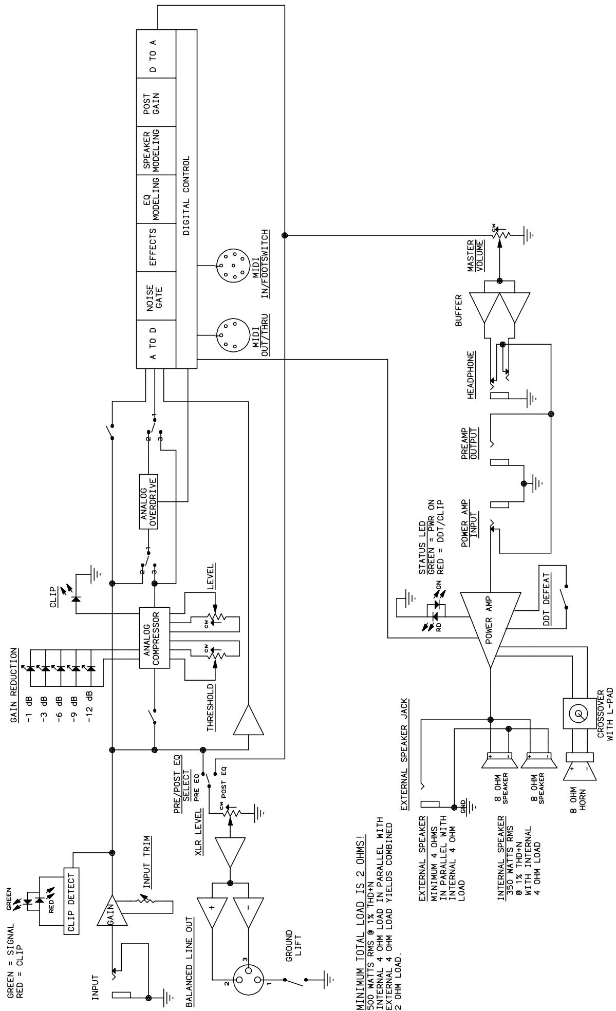
flowchart
graph TD
    A["GREEN = SIGNAL RED = CLIP"] --> B["RED"]
    B --> C["CLIP DETECT"]
    C --> D["INPUT"]
    D --> E["GAIN"]
    E --> F["INPUT TRIM"]
    F --> G["XLR LEVEL"]
    G --> H["PRE/POST EQ SELECT PRE EQ"]
    H --> I["ANALOG COMPRESSOR"]
    I --> J["ANALOG OVERDRIVE"]
    J --> K["A TO D"]
    K --> L["NOISE GATE"]
    L --> M["EFFECTS"]
    M --> N["EQ MODELING"]
    N --> O["SPEAKER MODELING"]
    O --> P["POST GAIN"]
    P --> Q["D TO A"]
    Q --> R["DIGITAL CONTROL"]
    R --> S["MIDI OUT/THRU"]
    R --> T["MIDI IN/FOOTSWITCH"]
    U["MINIMUM TOTAL LOAD IS 2 OHMS! 500 WATTS RMS @ 1% THD+N INTERNAL 4 OHM LOAD IN PARALLEL WITH EXTERNAL 4 OHM LOAD YIELDS COMBINED 2 OHM LOAD."] --> V["EXTERNAL SPEAKER JACK"]
    V --> W["8 OHM Speaker"]
    W --> X["POWER AMP INPUT"]
    X --> Y["PREAM OUTPUT"]
    Y --> Z["HEADPHONE"]
    Z --> AA["BUFFER"]
    AA --> AB["MASTER VOLUME"]
    AC["CROSSOVER WITH L-PAD"] --> AD["CROSSOVER WITH L-PAD"]
    AE["Ground LIFT"] --> AF["Ground LIFT"]
    AG["POWER AMP INPUT"] --> AH["DDT DEFEAT"]
    AI["STATUS LED GREEN = PWR ON RED = DDT/CLIP"] --> AJ["RD"]
    AK["STATUS LED GREEN = PWR ON RED = DDT/CLIP"] --> AL["GN"]
BAM™ SPECIFICATIONS
SYSTEM SPECIFICATIONS:
GENERAL:
- Mains circuit breaker: 6 amps (resettable)
• Power consumption: 500 Watts, 120 VAC 60 Hz
• Power consumption: 500 Watts, 230 VAC 50/60 Hz - Hum and noise: Typically greater than -80 dB unweighted
- Internal speakers: Two professional 10 inch cast frame 8-Ohm speakers wired in parallel for a total impedance of 4 Ohms. One Foster compression horn with crossover and tweeter protection.
DIMENSIONS:
• Height: 24 inches (including feet)
- Width: 23.5 inches
• Depth: 17.125 inches @ bottom, 13 inches @ top
• Weight: 93.5 lbs
POWER AMPLIFIER SECTION:
PROTECTION:
- Current limit protection circuit
• Thermal protection circuit
• D.C. crowbar - DDT™ speaker protection circuit with defeat switch
- Variable speed fan, thermally controlled
GENERAL INFO:
• Minimum load = 2 Ohms
- DDT dynamic range: +16 dB
- Input sensitivity: 1.0 V RMS
• One 1/4 inch external speaker jack
POWER AMPLIFIER INPUT:
- Input impedance: 15 k Ohms
- Sensitivity: 1 V RMS (to drive power amp to clipping)
- Switching jack provides preamp out to power amp in connection when not used
POWER OUTPUT:
- 500 Watts (31.62 V RMS) into 2 Ohms with no more than 1% THD+N
- 350 Watts (37.42 V RMS) into 4 Ohms with no more than 1% THD+N
HUM AND NOISE:
- Typically greater than 100 dB below full power @ 4 Ohms unweighted
FREQUENCY RESPONSE:
- +0/-1 dB, 100 mW to 300 W RMS 20 Hz to 20 kHz into 4 Ohms
PREAMPLIFIER SECTION:
D/A AND A/D CONVERSION:
- Rate: 44.1 kHz
• Quantization: 24 bit
SETTINGS FOR FOLLOWING MEASUREMENTS UNLESS OTHERWISE NOTED:
- Input trim set to highest level without triggering red clip indicator
- Compressor = Out
- Pre-gain = Not applicable to this model
- Bass = 0 (12 o'clock)
• Mid = 0 (12 o'clock)
• Mid-shift = 0 (12 o'clock)
• High = 0 (12 o'clock) - Post-gain = 5
- Effects = Off
- Amp model = RED
- Speaker model = BAM 210
INPUT SENSITIVITY (Level to achieve full power):
• Nominal input: 300 mV RMS
- Minimum input: 25 mV RMS (input trim, post-gain and master fully CW)
- Maximum input: 7 V RMS (maximum signal at input before preamp clipping occurs)
PREAMP OUTPUT:
• Nominal output level: 1 V RMS
- Load impedance: 1,000 Ohms minimum
EXTERNAL FOOTSWITCH FUNCTIONS:
- Preset/bank selection
- Remote tuner access/display
- Tweeter on/off selection
• Effects on/off selection
• Effects alternate settings - Compressor on/off
- Boost function (Allows alternate level and EQ settings)
ESPAÑOL
BAM™ 210
natural_image
Front view of a black industrial control unit with grid and indicator lights (no visible text or symbols)CARACTERÍSITCAS
| Effect | Speed/Adj | Depth | Tweak 1 | Tweak 2 |
| Chorus | Speed | Depth | Crossover Frequency | |
| Flanger | Speed | Depth | Delay Time | Crossover Frequency |
| Phaser | Speed | Depth | - | - |
| Octave | Dry Level | Wet Level | Tone | - |
| Synth | Sensitivity | Mix | Frequency | Resonance |
| Fretless | Sensitivity | Mix | Frequency | Resonance |
| Funk Wah | Sensitivity | Mix | Frequency | Resonance |
| Distortion | Pre Gain | Post Gain | Low Rolloff | Dry Level |
IMPLEMENTACIÓN MIDI
| Address (Hex) | Name | Range (Decimal) |
| 00 | Model Selection | High nib is Cabinet Model, 0-7Low nib is Amp Model, 0-7Clockwise rotation for both nibs:0 = Red / 2x101 = 360 / 1x18::::7 = Freddie K / Alloy 4x10 |
| 01 | Hardware Control Bits | 0-3,7 =<reserved>4 = Compressor On5 = Analog Overdrive On6 = Tweeter On |
| 02 | 0 | |
| 03,04 | Pre Gain (non-boost, boost) | 1-33 (active when Analog Overdrive enabled) |
| 05,06 | Low (non-boost, boost) | 1-33 |
| 07,08 | Mid (non-boost, boost) | 1-33 |
| 09,0A | Mid Shift (non-boost, boost) | 1-33 |
| 0B,0C | High (non-boost, boost) | 1-33 |
| 0D,0E | Post Gain (non-boost, boost) | 0-33 (0 = reverb off) |
| 0F,10 | 0 | |
| 11,12 | Speed/Adj (primary/off, secondary/on) | 1-25 |
| 13,14 | Depth (primary/off, secondary/on) | 0-25 (0 = modulation off) |
| 15 | Effect Type | 0-7 = Chorus, Flanger, Phaser, Octave, Synth, Fretless, Funk Wah, Distortion |
| 16 | Effect Tweak 1 | 1-25; 255=no tweak *(see below) |
| 17 | Effect Tweak 2 | 1-25; 255=no tweak *(see below) |
| 18-1D | 0 | |
| 1E | EFX Mode Status Bits (Soft) | High nib is<reserved>Low nib is EFX mode status:Bit 0 is Boost (on/secondary = high)Bit 1 is<reserved>Bit 2 is Effect On (on = high)Bit 3 is Effect Alt. (on/secondary = high) |
Values are automatically set with effect selection, adjust after to tweak. Available tweaks are shown in table below.
| Tweak 1 | Tweak 2 | |
| Chorus | - | Crossover Frequency |
| Flanger | Delay Time | Crossover Frequency |
| Phaser | - | - |
| Octave | Tone | - |
| Synth | Frequency | Resonance |
| Fretless | Frequency | Resonance |
| Funk Wah | Frequency | Resonance |
| Distortion | Low Rolloff | Dry Level |
GLOBALS
| Offset (Hex) | Name | Range (Decimal) |
| 00 | Reserved (keep at zero) | |
| 01 | Bank Select Method | 0 = Preset (1-4) stays the same after bank select (default)1 = Preset goes to #1 after bank select2 = Preset light blinks, waits for user preset selection |
| 02 | PFC4B All Info | 0 = Inactive mode - LEDs off1 = Inactive mode - LEDs dim (default)2 = Inactive mode - LEDs bright for both modes |
| 03 | MIDI Channel (- 1) | 0-15 for 1-16 (default = 0, channel 1) |
| 04 | Global Bits | Bit 0 set for User patches at powerup (default = 0, factory)Bits 1-7 are reserved (keep at zero) |
| 05 | Noise Gate Threshold | 0=off, 1-25 (default = 0) |
| 06 | Noise Gate Sensitivity | 0-25 (default = 5) |
| 07 | Reserved (keep at 0) | |
| 08 | Reserved (keep at 0) | |
| 09 | Tuner Bits | Bit 0 set for Eb mode (default = 0, standard E mode)Bit 1 set for Chromatic mode (default = 0, bass mode)Bits 2-7 are reserved (keep at 0) |
| 0A | Tuner Volume Level | 0-25. Default is 0 (muted). |
| 0B | Reserved (keep at 0) | |
| 0C | Reserved (keep at 0) | |
| 0D | Reserved (keep at 0) |
natural_image
Front view of a black industrial control unit with grid and indicator lights (no visible text or labels)CARACTERISTIQUES
(11) GAIN REDUCTION LEDs
(25) IEC MAINS CONNECTOR
(27) MIDI OUT / THRU
BOOST/EFFECTS LEVELS
| Effect | Speed/Adj | Depth | Tweak 1 | Tweak 2 |
| Chorus | Speed | Depth | Crossover Frequency | |
| Flanger | Speed | Depth | Delay Time | Crossover Frequency |
| Phaser | Speed | Depth | - | - |
| Octave | Dry Level | Wet Level | Tone | - |
| Synth | Sensitivity | Mix | Frequency | Resonance |
| Fretless | Sensitivity | Mix | Frequency | Resonance |
| Funk Wah | Sensitivity | Mix | Frequency | Resonance |
| Distortion | Pre Gain | Post Gain | Low Roll off | Dry Level |
MIDI IMPLEMENTATION
The BAM ^™ is designed to be an all-in-one bass amplification system using the PFC4B footswitch. However, there are plenty of other uses for those MIDI jacks on the back, and that's what we'll cover here. We'll start with the simpler stuff, and move on to the more complicated stuff later.
MIDI CHANNEL
| Address (Hex) | Name | Range (Decimal) |
| 00 | Model Selection | High nib is Cabinet Model, 0-7Low nib is Amp Model, 0-7Clockwise rotation for both nibs:0 = Red / 2x101 = 360 / 1x18::::7 = Freddie K / Alloy 4x10 |
| 01 | Hardware Control Bits | 0-3,7 =<reserved>4 = Compressor On5 = Analog Overdrive On6 = Tweeter On |
| 02 | 0 | |
| 03,04 | Pre Gain (non-boost, boost) | 1-33 (active when Analog Overdrive enabled) |
| 05,06 | Low (non-boost, boost) | 1-33 |
| 07,08 | Mid (non-boost, boost) | 1-33 |
| 09,0A | Mid Shift (non-boost, boost) | 1-33 |
| 0B,0C | High (non-boost, boost) | 1-33 |
| 0D,0E | Post Gain (non-boost, boost) | 0-33 (0 = reverb off) |
| 0F,10 | 0 | |
| 11,12 | Speed/Adj (primary/off, secondary/on) | 1-25 |
| 13,14 | Depth (primary/off, secondary/on) | 0-25 (0 = modulation off) |
| 15 | Effect Type | 0-7 = Chorus, Flanger, Phaser, Octave, Synth, Fretless, Funk Wah, Distortion |
| 16 | Effect Tweak 1 | 1-25; 255=no tweak *(see below) |
| 17 | Effect Tweak 2 | 1-25; 255=no tweak *(see below) |
| 18-1D | 0 | |
| 1E | EFX Mode Status Bits (Soft) | High nib is<reserved>Low nib is EFX mode status:Bit 0 is Boost (on/secondary = high)Bit 1 is<reserved>Bit 2 is Effect On (on = high)Bit 3 is Effect Alt. (on/secondary = high) |
Values are automatically set with effect selection, adjust after to tweak. Available tweaks are shown in table below.
| Tweak 1 | Tweak 2 | |
| Chorus | - | Crossover Frequency |
| Flanger | Delay Time | Crossover Frequency |
| Phaser | - | - |
| Octave | Tone | - |
| Synth | Frequency | Resonance |
| Fretless | Frequency | Resonance |
| Funk Wah | Frequency | Resonance |
| Distortion | Low Rolloff | Dry Level |
GLOBALS
| Offset (Hex) | Name | Range (Decimal) |
| 00 | Reserved (keep at zero) | |
| 01 | Bank Select Method | 0 = Preset (1-4) stays the same after bank select (default)1 = Preset goes to #1 after bank select2 = Preset light blinks, waits for user preset selection |
| 02 | PFC4B All Info | 0 = Inactive mode - LEDs off1 = Inactive mode - LEDs dim (default)2 = Inactive mode - LEDs bright for both modes |
| 03 | MIDI Channel (- 1) | 0-15 for 1-16 (default = 0, channel 1) |
| 04 | Global Bits | Bit 0 set for User patches at powerup (default = 0, factory)Bits 1-7 are reserved (keep at zero) |
| 05 | Noise Gate Threshold | 0=off, 1-25 (default = 0) |
| 06 | Noise Gate Sensitivity | 0-25 (default = 5) |
| 07 | Reserved (keep at 0) | |
| 08 | Reserved (keep at 0) | |
| 09 | Tuner Bits | Bit 0 set for Eb mode (default = 0, standard E mode)Bit 1 set for Chromatic mode (default = 0, bass mode)Bits 2-7 are reserved (keep at 0) |
| 0A | Tuner Volume Level | 0-25. Default is 0 (muted). |
| 0B | Reserved (keep at 0) | |
| 0C | Reserved (keep at 0) | |
| 0D | Reserved (keep at 0) |
BAM™ SPECIFICATIONS
SYSTEM SPECIFICATIONS:
GENERAL:
- Mains circuit breaker: 6 amps (resettable)
• Power consumption: 500 Watts, 120 VAC 60 Hz
• Power consumption: 500 Watts, 230 VAC 50/60 Hz - Hum and noise: Typically greater than -80 dB unweighted
- Internal speakers: Two professional 10 inch cast frame 8-Ohm speakers wired in parallel for a total impedance of 4 Ohms. One Foster compression horn with crossover and tweeter protection.
DIMENSIONS:
• Height: 24 inches (including feet)
- Width: 23.5 inches
• Depth: 17.125 inches @ bottom, 13 inches @ top
• Weight: 93.5 lbs
POWER AMPLIFIER SECTION:
PROTECTION:
- Current limit protection circuit
• Thermal protection circuit
• D.C. crowbar - DDT™ speaker protection circuit with defeat switch
- Variable speed fan, thermally controlled
GENERAL INFO:
• Minimum load = 2 Ohms
- DDT dynamic range: +16 dB
- Input sensitivity: 1.0 V RMS
• One 1/4 inch external speaker jack
POWER AMPLIFIER INPUT:
- Input impedance: 15 k Ohms
- Sensitivity: 1 V RMS (to drive power amp to clipping)
- Switching jack provides preamp out to power amp in connection when not used
POWER OUTPUT:
- 500 Watts (31.62 V RMS) into 2 Ohms with no more than 1% THD+N
- 350 Watts (37.42 V RMS) into 4 Ohms with no more than 1% THD+N
HUM AND NOISE:
- Typically greater than 100 dB below full power @ 4 Ohms unweighted
FREQUENCY RESPONSE:
- +0/-1 dB, 100 mW to 300 W RMS 20 Hz to 20 kHz into 4 Ohms
PREAMPLIFIER SECTION:
D/A AND A/D CONVERSION:
- Rate: 44.1 kHz
• Quantization: 24 bit
SETTINGS FOR FOLLOWING MEASUREMENTS UNLESS OTHERWISE NOTED:
- Input trim set to highest level without triggering red clip indicator
- Compressor = Out
- Pre-gain = Not applicable to this model
- Bass = 0 (12 o'clock)
• Mid = 0 (12 o'clock)
• Mid-shift = 0 (12 o'clock)
• High = 0 (12 o'clock) - Post-gain = 5
- Effects = Off
- Amp model = RED
- Speaker model = BAM 210
INPUT SENSITIVITY (Level to achieve full power):
• Nominal input: 300 mV RMS
- Minimum input: 25 mV RMS (input trim, post-gain and master fully CW)
- Maximum input: 7 V RMS (maximum signal at input before preamp clipping occurs)
PREAMP OUTPUT:
• Nominal output level: 1 V RMS
- Load impedance: 1,000 Ohms minimum
EXTERNAL FOOTSWITCH FUNCTIONS:
- Preset/bank selection
- Remote tuner access/display
- Tweeter on/off selection
• Effects on/off selection
• Effects alternate settings - Compressor on/off
- Boost function (Allows alternate level and EQ settings)
DEUTSCH
BAM ^TM 210
natural_image
Front view of a gray industrial control unit with grid and indicator lights (no visible text or symbols)(11) GAIN REDUCTION-LEDs
(28) MIDI IN/FOOTSWITCH
| Effect | Speed/Adj | Depth | Tweak 1 | Tweak 2 |
| Chorus | Speed | Depth | Crossover Frequency | |
| Flanger | Speed | Depth | Delay Time | Crossover Frequency |
| Phaser | Speed | Depth | - | - |
| Octave | Dry Level | Wet Level | Tone | - |
| Synth | Sensitivity | Mix | Frequency | Resonance |
| Fretless | Sensitivity | Mix | Frequency | Resonance |
| Funk Wah | Sensitivity | Mix | Frequency | Resonance |
| Distortion | Pre Gain | Post Gain | Low Rolloff | Dry Level |
| Address (Hex) | Name | Range (Decimal) |
| 00 | Model Selection | High nib is Cabinet Model, 0-7Low nib is Amp Model, 0-7Clockwise rotation for both nibs:0 = Red / 2x101 = 360 / 1x18::::7 = Freddie K / Alloy 4x10 |
| 01 | Hardware Control Bits | 0-3,7 =<reserved>4 = Compressor On5 = Analog Overdrive On6 = Tweeter On |
| 02 | 0 | |
| 03,04 | Pre Gain (non-boost, boost) | 1-33 (active when Analog Overdrive enabled) |
| 05,06 | Low (non-boost, boost) | 1-33 |
| 07,08 | Mid (non-boost, boost) | 1-33 |
| 09,0A | Mid Shift (non-boost, boost) | 1-33 |
| 0B,0C | High (non-boost, boost) | 1-33 |
| 0D,0E | Post Gain (non-boost, boost) | 0-33 (0 = reverb off) |
| 0F,10 | 0 | |
| 11,12 | Speed/Adj (primary/off, secondary/on) | 1-25 |
| 13,14 | Depth (primary/off, secondary/on) | 0-25 (0 = modulation off) |
| 15 | Effect Type | 0-7 = Chorus, Flanger, Phaser, Octave, Synth, Fretless, Funk Wah, Distortion |
| 16 | Effect Tweak 1 | 1-25; 255=no tweak *(see below) |
| 17 | Effect Tweak 2 | 1-25; 255=no tweak *(see below) |
| 18-1D | 0 | |
| 1E | EFX Mode Status Bits (Soft) | High nib is<reserved>Low nib is EFX mode status:Bit 0 is Boost (on/secondary = high)Bit 1 is<reserved>Bit 2 is Effect On (on = high)Bit 3 is Effect Alt. (on/secondary = high) |
Values are automatically set with effect selection, adjust after to tweak. Available tweaks are shown in table below.
| Tweak 1 | Tweak 2 | |
| Chorus | - | Crossover Frequency |
| Flanger | Delay Time | Crossover Frequency |
| Phaser | - | - |
| Octave | Tone | - |
| Synth | Frequency | Resonance |
| Fretless | Frequency | Resonance |
| Funk Wah | Frequency | Resonance |
| Distortion | Low Rolloff | Dry Level |
GLOBALS
| Offset (Hex) | Name | Range (Decimal) |
| 00 | Reserved (keep at zero) | |
| 01 | Bank Select Method | 0 = Preset (1-4) stays the same after bank select (default)1 = Preset goes to #1 after bank select2 = Preset light blinks, waits for user preset selection |
| 02 | PFC4B All Info | 0 = Inactive mode - LEDs off1 = Inactive mode - LEDs dim (default)2 = Inactive mode - LEDs bright for both modes |
| 03 | MIDI Channel (- 1) | 0-15 for 1-16 (default = 0, channel 1) |
| 04 | Global Bits | Bit 0 set for User patches at powerup (default = 0, factory)Bits 1-7 are reserved (keep at zero) |
| 05 | Noise Gate Threshold | 0=off, 1-25 (default = 0) |
| 06 | Noise Gate Sensitivity | 0-25 (default = 5) |
| 07 | Reserved (keep at 0) | |
| 08 | Reserved (keep at 0) | |
| 09 | Tuner Bits | Bit 0 set for Eb mode (default = 0, standard E mode)Bit 1 set for Chromatic mode (default = 0, bass mode)Bits 2-7 are reserved (keep at 0) |
| 0A | Tuner Volume Level | 0-25. Default is 0 (muted). |
| 0B | Reserved (keep at 0) | |
| 0C | Reserved (keep at 0) | |
| 0D | Reserved (keep at 0) |
BAM™ SPECIFICATIONS
SYSTEM SPECIFICATIONS:
GENERAL:
- Mains circuit breaker: 6 amps (resettable)
• Power consumption: 500 Watts, 120 VAC 60 Hz
• Power consumption: 500 Watts, 230 VAC 50/60 Hz - Hum and noise: Typically greater than -80 dB unweighted
- Internal speakers: Two professional 10 inch cast frame 8-Ohm speakers wired in parallel for a total impedance of 4 Ohms. One Foster compression horn with crossover and tweeter protection.
DIMENSIONS:
• Height: 24 inches (including feet)
- Width: 23.5 inches
• Depth: 17.125 inches @ bottom, 13 inches @ top
• Weight: 93.5 lbs
POWER AMPLIFIER SECTION:
PROTECTION:
- Current limit protection circuit
• Thermal protection circuit
• D.C. crowbar - DDT™ speaker protection circuit with defeat switch
- Variable speed fan, thermally controlled
GENERAL INFO:
• Minimum load = 2 Ohms
- DDT dynamic range: +16 dB
- Input sensitivity: 1.0 V RMS
• One 1/4 inch external speaker jack
POWER AMPLIFIER INPUT:
- Input impedance: 15 k Ohms
- Sensitivity: 1 V RMS (to drive power amp to clipping)
- Switching jack provides preamp out to power amp in connection when not used
POWER OUTPUT:
- 500 Watts (31.62 V RMS) into 2 Ohms with no more than 1% THD+N
- 350 Watts (37.42 V RMS) into 4 Ohms with no more than 1% THD+N
HUM AND NOISE:
- Typically greater than 100 dB below full power @ 4 Ohms unweighted
FREQUENCY RESPONSE:
- +0/-1 dB, 100 mW to 300 W RMS 20 Hz to 20 kHz into 4 Ohms
PREAMPLIFIER SECTION:
D/A AND A/D CONVERSION:
- Rate: 44.1 kHz
• Quantization: 24 bit
SETTINGS FOR FOLLOWING MEASUREMENTS UNLESS OTHERWISE NOTED:
- Input trim set to highest level without triggering red clip indicator
- Compressor = Out
- Pre-gain = Not applicable to this model
- Bass = 0 (12 o'clock)
• Mid = 0 (12 o'clock)
• Mid-shift = 0 (12 o'clock)
• High = 0 (12 o'clock) - Post-gain = 5
- Effects = Off
- Amp model = RED
- Speaker model = BAM 210
INPUT SENSITIVITY (Level to achieve full power):
• Nominal input: 300 mV RMS
- Minimum input: 25 mV RMS (input trim, post-gain and master fully CW)
- Maximum input: 7 V RMS (maximum signal at input before preamp clipping occurs)
PREAMP OUTPUT:
• Nominal output level: 1 V RMS
- Load impedance: 1,000 Ohms minimum
EXTERNAL FOOTSWITCH FUNCTIONS:
- Preset/bank selection
- Remote tuner access/display
- Tweeter on/off selection
• Effects on/off selection
• Effects alternate settings - Compressor on/off
- Boost function (Allows alternate level and EQ settings)
PEAVEY ELECTRONICS CORPORATION LIMITED WARRANTY
Effective Date: July 1, 1998
What This Warranty Covers
Your Peavey Warranty covers defects in material and workmanship in Peavey products purchased and serviced in the U.S.A. and Canada.
What This Warranty Does Not Cover
The Warranty does not cover: (1) damage caused by accident, misuse, abuse, improper installation or operation, rental, product modification or neglect; (2) damage occurring during shipment; (3) damage caused by repair or service performed by persons not authorized by Peavey; (4) products on which the serial number has been altered, defaced or removed; (5) products not purchased from an Authorized Peavey Dealer.
Who This Warranty Protects
This Warranty protects only the original retail purchaser of the product.
How Long This Warranty Lasts
The Warranty begins on the date of purchase by the original retail purchaser. The duration of the Warranty is as follows:
| Product Category | Duration |
| Guitars/Basses, Amplifiers, Pre-Amplifiers, Mixers, Electronic Crossovers and Equalizers | 2 years *(+ 3 years) |
| Drums | 2 years *(+ 1 year) |
| Enclosures | 3 years *(+ 2 years) |
| Digital Effect Devices and Keyboard and MIDI Controllers | 1 year *(+ 1 year) |
| Microphones | 2 years |
| Speaker Components (incl. speakers, baskets, drivers, diaphragm replacement kits and passive crossovers) and all Accessories | 1 year |
| Tubes and Meters | 90 days |
[*Denotes additional warranty period applicable if optional Warranty Registration Card is completed and returned to Peavey by original retail purchaser within 90 days of purchase.]
What Peavey Will Do
We will repair or replace (at Peavey's discretion) products covered by warranty at no charge for labor or materials. If the product or component must be shipped to Peavey for warranty service, the consumer must pay initial shipping charges. If the repairs are covered by warranty, Peavey will pay the return shipping charges.
How To Get Warranty Service
(1) Take the defective item and your sales receipt or other proof of date of purchase to your Authorized Peavey Dealer or Authorized Peavey Service Center.
(2) Ship the defective item, prepaid, to Peavey Electronics Corporation, International Service Center, 412 Highway 11 & 80 East, Meridian, MS 39301 or Peavey Canada Ltd., 95 Shields Court, Markham, Ontario, Canada L3R 9T5. Include a detailed description of the problem, together with a copy of your sales receipt or other proof of date of purchase as evidence of warranty coverage. Also provide a complete return address.
OR
Limitation of Implied Warranties
ANY IMPLIED WARRANTIES, INCLUDING WARRANTIES OF MERCHANTABILITY AND FITNESS FOR A PARTICULAR PURPOSE, ARE LIMITED IN DURATION TO THE LENGTH OF THIS WARRANTY.
Some states do not allow limitations on how long an implied warranty lasts, so the above limitation may not apply to you.
Exclusions of Damages
PEAVEY'S LIABILITY FOR ANY DEFECTIVE PRODUCT IS LIMITED TO THE REPAIR OR REPLACEMENT OF THE PRODUCT, AT PEAVEY'S OPTION. IF WE ELECT TO REPLACE THE PRODUCT, THE REPLACEMENT MAY BE A RECONDITIONED UNIT. PEAVEY SHALL NOT BE LIABLE FOR DAMAGES BASED ON INCONVENIENCE, LOSS OF USE, LOST PROFITS, LOST SAVINGS, DAMAGE TO ANY OTHER EQUIPMENT OR OTHER ITEMS AT THE SITE OF USE, OR ANY OTHER DAMAGES WHETHER INCIDENTAL, CONSEQUENTIAL OR OTHERWISE, EVEN IF PEAVEY HAS BEEN ADVISED OF THE POSSIBILITY OF SUCH DAMAGES.
Some states do not allow the exclusion or limitation of incidental or consequential damages, so the above limitation or exclusion may not apply to you.
This Warranty gives you specific legal rights, and you may also have other rights which vary from state to state.
If you have any questions about this warranty or service received or if you need assistance in locating an Authorized Service Center, please contact the Peavey International Service Center at (601) 483-5365 / Peavey Canada Ltd. at (905) 475-2578.
Features and specifications subject to change without notice.
IMPORTANT SAFETY INSTRUCTIONS
WARNING: When using electric products, basic cautions should always be followed, including the following:
- Read all safety and operating instructions before using this product.
- All safety and operating instructions should be retained for future reference.
- Obey all cautions in the operating instructions and on the back of the unit.
- All operating instructions should be followed.
- This product should not be used near water (i.e., a bathtub, sink, swimming pool, wet basement, etc.)
- This product should be located so that its position does not interfere with its proper ventilation. It should not be placed flat against a wall or placed in a built-in enclosure that will impede the flow of cooling air.
- This product should not be placed near a source of heat such as a stove, radiator, or another heat producing amplifier.
- Connect only to a power supply of the type marked on the unit adjacent to the power supply cord.
- Never break off the ground pin on the power supply cord. For more information on grounding, write for our free booklet “Shock Hazard and Grounding.”
- Power supply cords should always be handled carefully. Never walk on or place equipment on power supply cords. Periodically check cords for cuts or signs of stress, especially at the plug and the point where the cord exits the unit.
- The power supply cord should be unplugged when the unit is to be unused for long periods of time.
- If this product is to be mounted in an equipment rack, rear support should be provided.
- Metal parts can be cleaned with a damp rag. The vinyl covering used on some units can be cleaned with a damp rag or an ammonia-based household cleaner if necessary. Disconnect unit from power supply before cleaning.
- Care should be taken so that objects do not fall and liquids are not spilled into the unit through the ventilation holes or any other openings.
- This unit should be checked by a qualified service technician if:
a. The power supply cord or plug has been damaged.
b. Anything has fallen or been spilled into the unit.
c. The unit does not operate correctly.
d. The unit has been dropped or the enclosure damaged.
-
The user should not attempt to service this equipment. All service work should be done by a qualified service technician.
-
This product should be used only with a cart or stand that is recommended by Peavey Electronics.
-
Exposure to extremely high noise levels may cause a permanent hearing loss. Individuals vary considerably in susceptibility to noise induced hearing loss, but nearly everyone will lose some hearing if exposed to sufficiently intense noise for a sufficient time. The U.S. Government's Occupational Safety and Health Administration (OSHA) has specified the following permissible noise level exposures.
| Duration Per Day In Hours | Sound Level dBA, Slow Response |
| 8 | 90 |
| 6 | 92 |
| 4 | 95 |
| 3 | 97 |
| 2 | 100 |
| 1 1/2 | 102 |
| 1 | 105 |
| 1/2 | 110 |
| 1/4 or less | 115 |
According to OSHA, any exposure in excess of the above permissible limits could result in some hearing loss. Ear plugs or protectors for the ear canals or over the ears must be worn when operating this amplification system in order to prevent a permanent hearing loss if exposure is in excess of the limits as set forth above. To ensure against potentially dangerous exposure to high sound pressure levels, it is recommended that all persons exposed to equipment capable of producing high sound pressure levels such as this amplification system be protected by hearing protectors while this unit is in operation.
SAVE THESE INSTRUCTIONS!

natural_image
Abstract black geometric logo design with stylized arrow-like shapes (no text or symbols)LISTEN TO THIS™
Features and specifications subject to change without notice.
Peavey Electronics Corporation • 711 A Street • Meridian • MS • 39301
(601) 483-5365 • FAX (601) 486-1278 • www.peavey.com

80305007