
A-A-AC8 - Preamplifier PEAVEY - Free user manual and instructions
Find the device manual for free A-A-AC8 PEAVEY in PDF.

| Product Type | 8-Channel Amplifier Controller / Preamplifier |
| Brand | PEAVEY |
| Model | A-A-AC8 |
| Category | Preamplifier |
| Number of Channels | 8 |
| Network Communication | RS-485 half-duplex, shielded 2-conductor cable, up to 1220 m |
| Amplifier Connectors | 8 RJ-45 inputs (for ACI-2 or IDC 150TII modules) |
| Monitor Audio Connectors | Differential audio inputs and outputs for Monitor 1 and Monitor 2 |
| Potentiometers | Monitor input balance and Monitor channel potentiometers |
| Power Supply | AC mains, removable cord, On/Off switch |
| LED Indicators | Power LED (red), Network LED (activity) |
| Unit Identification | 8-pin DIP switch (binary address) |
| Max Number of Units | 32 on RS-485 network |
| Operating Temperature | 0°C to 40°C (estimated) |
| Safety | Do not open – risk of electric shock. Refer servicing to qualified personnel. |
| Maintenance | No user-serviceable parts. Clean with a dry cloth. |
| Weight | Approximately 2 kg (estimated) |
| Warranty | Not specified |
Frequently Asked Questions - A-A-AC8 PEAVEY
User questions about A-A-AC8 PEAVEY
0 question about this device. Answer the ones you know or ask your own.
Ask a new question about this device
Download the instructions for your Preamplifier in PDF format for free! Find your manual A-A-AC8 - PEAVEY and take your electronic device back in hand. On this page are published all the documents necessary for the use of your device. A-A-AC8 by PEAVEY.
USER MANUAL A-A-AC8 PEAVEY
Intended to alert the user to the presence of uninsulated "dangerous voltage" within the product's enclosure that may be of sufficient magnitude to constitute a risk of electric shock to persons.

Intended to alert the user of the presence of important operating and maintenance (servicing) instructions in the literature accompanying the product.
CAUTION: Risk of electrical shock - DO NOT OPEN!
CAUTION: To reduce the risk of electric shock, do not remove cover. No user serviceable parts inside. Refer servicing to qualified service personnel.
WARNING: To prevent electrical shock or fire hazard, do not expose this appliance to rain or moisture. Before using this appliance, read the operating guide for further warnings.

The A/A-AC8™ eight-channel amp controller provides the means for a MediaMatrix® system to monitor and control up to eight amplifier channels. With MediaMatrix® amp control software, the A/A-AC8 will monitor an amplifier's load current and load voltage, determine the operational status of the amplifier, and control the amplifier's power on/off. Communications between the A/A-AC8 and the MediaMatrix system are accomplished via a proprietary serial communications protocol over industry standard RS-485, which can operate up to lengths of 4,000 feet.
Note: An RS-485 communications card is required in the MediaMatrix—contact Peavey Architectural Acoustics® tech support for more information.
Communications between the A/A-AC8 and an amplifier are accomplished through a standard 8-conductor RJ-45 telephone-type cable. The A/A-AC8 will communicate with any Peavey amplifier equipped with an ACI^TM -2 module or an IDC^TM 150TII.
Front Panel:

FRONT PANEL FEATURES
POWER LED (1)
Illuminates when unit is on.
NETWORK LED (2)
Illuminates when there is communication activity on the RS-485 network.
Rear Panel:
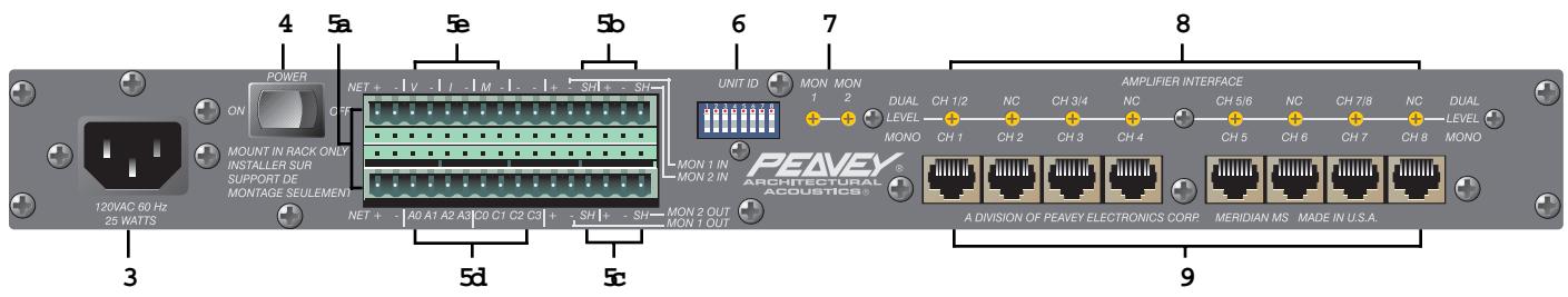
REAR PANEL FEATURES
AC LINE CORD SOCKET (3)

Provided to accept the removable AC line cord.
POWER SWITCH (4)
Switch to "On" position to turn on. The red Power LED will illuminate indicating power is being supplied to the unit.
2X16 PHOENIX-TYPE CONNECTOR (5)
a. RS-485 Network Communication Connections.
b. Monitor 1 and Monitor 2 Differential Audio inputs.
c. Monitor 1 and Monitor 2 Differential Audio outputs.
d. Parallel Command Interface (future use).
e. Analog amplifier Voltage, Current, and Status outputs (future use).
UNIT ID 8-PIN DIP (6)
Defines the unit location on the RS-485 network.
MONITOR 1 & MONITOR 2 INPUT TRIM POTS (7)
Determine the level of the Monitor Input signals that get mixed to the Monitor Outputs.
CHANNEL MONITOR TRIM POTS (8)
Determine the level of the amplifier signals that get mixed to the Monitor Outputs.
AMPLIFIER INPUTS (9)
RJ-45 connector inputs from an amplifier's ACI-2 module.
CONNECTING THE A/A-AC8 TO THE MEDIAMATRIX SYSTEM
The A/A-AC8 communicates with the MediaMatrix system via an RS-485 multi-drop network. Communications are half-duplex and require a two-conductor, shielded cable (24 AWG twisted pair telephone cable is recommended).
Figure 1 shows an example of a MediaMatrix-A/A-AC8 RS-485 network.
figure 1
The RS-485 network should be terminated with 120 resistors. This is especially important when the network approaches its maximum length of 4,000 feet. A maximum of 32 A/A-AC8s may be connected to the RS-485 network.
Figure 2 shows the wiring of an A/A-AC8 to the RS-485 network.
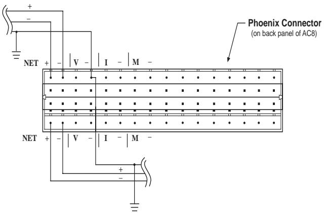
figure 2
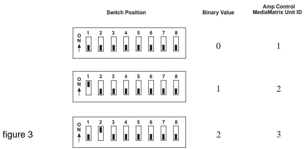
SETTING THE UNIT ID 8-PIN DIP SWITCH
The Unit ID 8-pin DIP switch on the back of the A/A-AC8 defines the address of the unit in the RS-485 network. The 8-pin DIP switch represents a binary number, with position 1 being the least significant bit, position 5 being the most significant bit. (Only the first five switches are used.) The UP or ON position of a switch represents a binary 1, while the DOWN or OFF position of a switch represents a binary 0. Notice that all switches OFF is equivalent to binary 0, but in the MediaMatrix amp control software view file, this defines location 1 in the AC8 Network. Note that each A/A-AC8 in the RS-485 Network must have its own unique unit ID location.
Figure 3 shows some Unit ID switch examples.
CONNECTING AN AMPLIFIER TO THE A/A-AC8
The A/A-AC8 communicates with an amplifier through an 8-conductor RJ-45 telephone-type cable. The amplifier must be equipped with an ACI-2 communications module. Communication with a dual channel (stereo) amplifier, such as the IA™ 400, requires two A/A-AC8 channels. The communication cable from the dual channel amp must be connected at the A/A-AC8's Amplifier Interface to one of the DUAL CH1/2, CH3/4, CH5/6, CH7/8 inputs, and the following input must remain unconnected. Single-channel (mono) amplifiers, such as the IDC™ 150TII, require only one A/A-AC8 channel. Single-channel amps may be connected to any A/A-AC8 Amplifier Interface input, except immediately following a dual channel amp input.
AMPLIFIER AUDIO MONITORING
The A/A-AC8 allows monitoring of an amplifier's audio signal. There are trim pots above each amplifier input which adjust the level of the amp's audio signal that gets mixed to the A/A-AC8's Monitor Outputs. The channel trim pot's 12 o'clock position corresponds to unity gain, with a maximum of +14 dB gain when fully clockwise. Any amp channel's audio signal can be routed to either of the two Monitor Outputs. The routing is accomplished within the MediaMatrix amp control software view. The Monitor 1 and Monitor 2 outputs are differentially driven, with a maximum output of +22 dBu. External audio inputs with trim pots (maximum unity gain) are provided for each Monitor channel. These may be used to chain A/A-AC8 monitor busses so that only one set of monitor audio cables need be routed to the control room.
Figure 4 shows a typical Amp Control audio monitor wiring using two-conductor, shielded audio cable.
figure 4
ESPAÑOL
NETWORK LED (LED de red) (2)
Dimensions & Weight:
1.75" H x 19" W x 11.25" D (excluding connectors)
8.2 pounds
Power Consumption:
Domestic: 25 watts, 60 Hz, 120VAC Export: 25 watts, 50/60 Hz, 230VAC
LIMITED WARRANTY
Peavey Electronics Corporation warrants to the original purchaser of this new Architectural Acoustics product that it is free from defects in material and workmanship. If within one (1) year from date of purchase a properly installed product proves to be defective and Peavey is notified, Peavey will repair or replace it at no charge. (Note: Batteries and patch cords not covered.) "Original purchaser" means the customer for whom the product is originally installed.
Damage resulting from improper installation, interconnection of a unit or system of another manufacturer, accident or unreasonable use, neglect or any other cause not arising from defects in material and workmanship is not covered by this warranty. The warranty is valid only as to products purchased and installed in the United States and Canada.
THIS LIMITED WARRANTY IS IN LIEU OF ANY AND ALL WARRANTYES, EXPRESSED OR IMPLIED, INCLUDING THE IMPLIED WARRANTYES OF MERCHANTABILITY AND FITNESS FOR A PARTICULAR USE. UNDER NO CIRCUMSTANCES WILL PEAVEY BE LIABLE FOR ANY LOST PROFITS, LOST SAVINGS, INCIDENTTAL DAMAGES OR CONSEQUENTIAL DAMAGES ARISING OUT OF THE USE OR INABILITY TO USE THE PRODUCT, EVEN IF PEAVEY HAS BEEN ADVISED OF THE POSSIBILITY OF SUCH DAMAGE. THIS LIMITED WARRANTY IS THE ONLY EXPRESSED WARRANTY ON THIS PRODUCT, AND NO OTHER STATEMENT, REPRESENTATION, WARRANTY, OR AGREEMENT BY ANY PERSON SHALL BE VALID OR BINDING UPON PEAVEY.
Peavey's liability to the original purchaser for damages for any cause whatsoever and regardless of the form of action is limited to the actual damages up to the greater of Five Hundred Dollars ($500) or an amount equal to the purchase price of the product that caused the damage or that is the subject of or is directly related to the cause of action. This limitation of liability will not apply to claims for personal injury or damage to real property or tangible personal property allegedly caused by Peavey's negligence. For information on service under this warranty, call a Peavey customer service representative at (601) 483-5376.
IMPORTANT SAFETY INSTRUCTIONS
WARNING: When using electric products, basic cautions should always be followed, including the following.
- Read all safety and operating instructions before using this product.
- All safety and operating instructions should be retained for future reference.
- Obey all cautions in the operating instructions and on the back of the unit.
- All operating instructions should be followed.
- This product should not be used near water, i.e., a bathtub, sink, swimming pool, wet basement, etc.
- This product should be located so that its position does not interfere with its proper ventilation. It should not be placed flat against a wall or placed in a built-in enclosure that will impede the flow of cooling air.
- This product should not be placed near a source of heat such as a stove, radiator, or another heat producing amplifier.
- Connect only to a power supply of the type marked on the unit adjacent to the power supply cord.
- Never break off the ground pin on the power supply cord. For more information on grounding, write for our free booklet "Shock Hazard and Grounding."
- Power supply cords should always be handled carefully. Never walk or place equipment on power supply cords. Periodically check cords for cuts or signs of stress, especially at the plug and the point where the cord exits the unit.
- The power supply cord should be unplugged when the unit is to be unused for long periods of time.
- If this product is to be mounted in an equipment rack, rear support should be provided.
- Metal parts can be cleaned with a damp rag. The vinyl covering used on some units can be cleaned with a damp rag or an ammonia-based household cleaner if necessary. Disconnect unit from power supply before cleaning.
- Care should be taken so that objects do not fall and liquids are not spilled into the unit through the ventilation holes or any other openings.
- This unit should be checked by a qualified service technician if:
a. The power supply cord or plug has been damaged.
b. Anything has fallen or been spilled into the unit.
c. The unit does not operate correctly.
d. The unit has been dropped or the enclosure damaged.
- The user should not attempt to service this equipment. All service work should be done by a qualified service technician.
- This product should be used only with a cart or stand that is recommended by Peavey Electronics.
- Exposure to extremely high noise levels may cause a permanent hearing loss. Individuals vary considerably in susceptibility to noise induced hearing loss, but nearly everyone will lose some hearing if exposed to sufficiently intense noise for a sufficient time.
The U.S. Government's Occupational Safety and Health Administration (OSHA) has specified the following permissible noise level exposures.
Duration Per Day In Hours
8
6
4
3
2
1 1/2
1
1/2
1/4 or less
Sound Level dBA, Slow Response
90
92
95
97
100
102
105
110
115
According to OSHA, any exposure in excess of the above permissible limits could result in some hearing loss. Ear plugs or protectors in the ear canals or over the ears must be worn when operating this amplification system in order to prevent a permanent hearing loss if exposure is in excess of the limits as set forth above. To ensure against potentially dangerous exposure to high sound pressure levels, it is recommended that all persons exposed to equipment capable of producing high sound pressure levels such as this amplification system be protected by hearing protectors while this unit is in operation.
SAVE THESE INSTRUCTIONS!

Features and specifications subject to change without notice.
