
CP1E - Programmable Controllers OMRON - Free user manual and instructions
Find the device manual for free CP1E OMRON in PDF.

| Product type | Programmable logic controller (PLC) |
| Brand | OMRON |
| Model | CP1E |
| Dimensions (L x W x H) | 130 x 90 x 85 mm |
| Weight | 450 g |
| Power supply | 24 VDC or 100-240 VAC depending on model |
| Maximum consumption | 20 W |
| Operating temperature | 0 to 55 °C |
| Ambient humidity | 10% to 90% without condensation |
| Program memory | 8K steps |
| Input voltage | 24 VDC |
| Output voltage | Relay 2 A (max) |
| Number of inputs | Up to 40 depending on model |
| Number of outputs | Up to 30 depending on model |
| Main functions | Control logic, timing, counting, arithmetic calculation, serial communication (RS-232C/485) |
| Maintenance and cleaning | Clean with a dry, soft cloth. Do not use solvents. |
| Safety | Disconnect power before any intervention. Respect rated voltages. |
| Spare parts | I/O expansion modules, programming cables, power supplies |
| Repairability | Entrust to a qualified technician. No user-serviceable parts. |
| General information | Used for industrial automation. Programming via CX-One software. |
Frequently Asked Questions - CP1E OMRON
User questions about CP1E OMRON
0 question about this device. Answer the ones you know or ask your own.
Ask a new question about this device
Download the instructions for your Programmable Controllers in PDF format for free! Find your manual CP1E - OMRON and take your electronic device back in hand. On this page are published all the documents necessary for the use of your device. CP1E by OMRON.
USER MANUAL CP1E OMRON
INSTRUCTIONS REFERENCE MANUAL
OMRON
OMRON, 2009
All rights reserved. No part of this publication may be reproduced, stored in a retrieval system, or transmitted, in any form, or by any means, mechanical, electronic, photocopying, recording, or otherwise, without the prior written permission of OMRON.
No patent liability is assumed with respect to the use of the information contained herein. Moreover, because OMRON is constantly striving to improve its high-quality products, the information contained in this manual is subject to change without notice. Every precaution has been taken in the preparation of this manual. Nevertheless, OMRON assumes no responsibility for errors or omissions. Neither is any liability assumed for damages resulting from the use of the information contained in this publication.
SYSMAC CP Series
CP1E-E□D□-□
CP1E-N□D□-□
CP1E-NA□□D□-□
CP1E CPU Unit
Instructions Reference Manual
Revised December 2009
Introduction
Thank you for purchasing a SYSMAC CP-series CP1E Programmable Controller.
This manual contains information required to use the CP1E. Read this manual completely and be sure you understand the contents before attempting to use the CP1E.
Intended Audience
This manual is intended for the following personnel, who must also have knowledge of electrical systems (an electrical engineer or the equivalent).
- Personnel in charge of installing FA systems
- Personnel in charge of designing FA systems
- Personnel in charge of managing FA systems and facilities
Applicable Products
- CP-series CP1E CPU Units
Basic Models CP1E-E□D□-□
A basic model of CPU Unit that support basic control applications using instructions such as basic, movement, arithmetic, and comparison instructions.
Application Models CP1E-N/NA□D□-□
An application model of CPU Unit that supports connections to Programmable Terminals, inverters, and servo drives.
The CP Series is centered around the CP1H, CP1L, and CP1E CPU Units and is designed with the same basic architecture as the CS and CJ Series.
Always use CP-series Expansion Units and CP-series Expansion I/O Units when expanding I/O capacity. I/O words are allocated in the same way as for the CPM1A/CPM2A PLCs, i.e., using fixed areas for inputs and outputs.
CP1E CPU Unit Manuals
Information on the CP1E CPU Units is provided in the following manuals.
Refer to the appropriate manual for the information that is required.
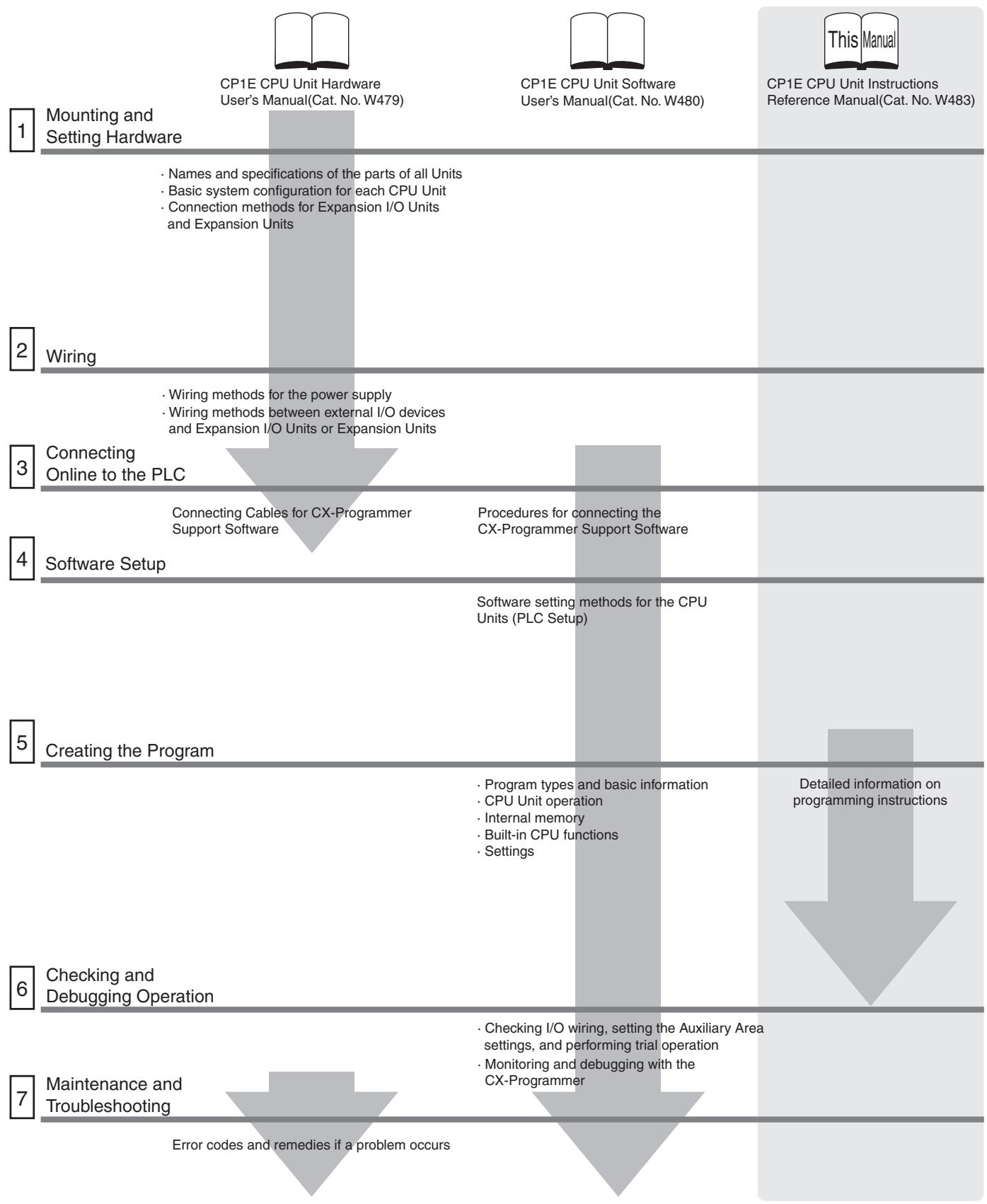
Manual Configuration
The CP1E CPU manuals are organized in the sections listed in the following tables. Refer to the appropriate section in the manuals as required.
CP1E CPU Unit Instructions Reference Manual (Cat. No. W483) (This Manual)
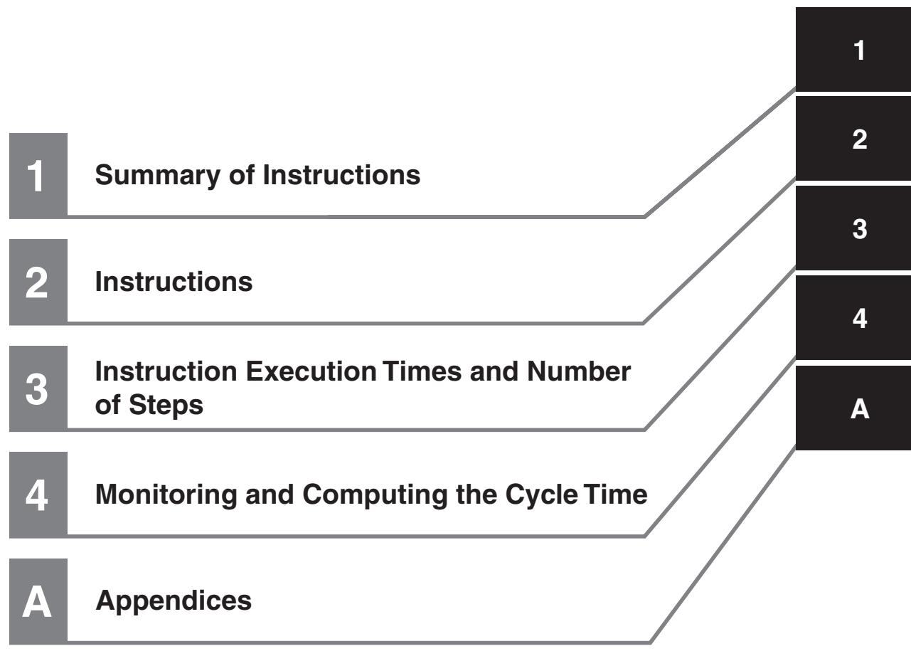
| Section | Contents |
| Section 1 Summary of Instructions | This section provides a summary of instructions used with a CP1E CPU Unit. |
| Section 2 Instruction | This section describes the functions, operands and sample programs of the instructions that are supported by a CP1E CPU Unit. |
| Section 3 Instruction Execution Times and Number of Steps | This section provides the execution times for all instructions used with a CP1E CPU Unit. |
| Section 4 Monitoring and Computing the Cycle Time | This section describes how to monitor and calculate the cycle time of a CP1E CPU Unit that can be used in the programs. |
| Appendices | The appendices provide a list of instructions by Mnemonic and ASCII code table for the CP1E CPU Unit. |
CP1E CPU Unit Software User's Manual (Cat. No. W480)
| Section | Contents |
| Section 1 Overview | This section gives an overview of the CP1E, describes its application procedures. |
| Section 2 CPU Unit Memory | This section describes the types of internal memory in a CP1E CPU Unit and the data that is stored. |
| Section 3 CPU Unit Operation | This section describes the operation of a CP1E CPU Unit. |
| Section 4 Programming Concepts | This section provides basic information on designing ladder programs for a CP1E CPU Unit. |
| Section 5 I/O Memory | This section describes the types of I/O memory areas in a CP1E CPU Unit and the details. |
| Section 6 I/O Allocation | This section describes I/O allocation used to exchange data between the CP1E CPU Unit and other units. |
| Section 7 PLC Setup | This section describes the PLC Setup, which are used to perform basic settings for a CP1E CPU Unit. |
| Section 8 Overview and Allocation of Built-in Functions | This section lists the built-in functions and describes the overall application flow and the allocation of the functions. |
| Section 9 Quick-response Inputs | This section describes the quick-response inputs that can be used to read signals that are shorter than the cycle time. |
| Section 10 Interrupts | This section describes the interrupts that can be used with CP1E PLCs, including input interrupts and scheduled interrupts. |
| Section 11 High-speed Counters | This section describes the high-speed counter inputs, high-speed counter interrupts, and the frequency measurement function. |
| Section 12 Pulse Outputs | This section describes positioning functions such as trapezoidal control, jogging, and origin searches. |
| Section 13 PWM Outputs | This section describes the variable-duty-factor pulse (PWM) outputs. |
| Section 14 Serial Communications | This section describes communications with Programmable Terminals (PTs) without using communications programming, no-protocol communications with general components, and connections with a Modbus-RTU Easy Master, Serial PLC Link, and host computer. |
| Section 15 Analog I/O Function | This section describes the built-in analog function for NA-type CPU Units. |
| Section 16 Built-in Functions | This section describes PID temperature control, clock functions, DM backup functions, security functions. |
| Section 17 Operating the Program- ming Device | This section describes basic functions of the CX-Programmer, such as using the CX-Programmer to write ladder programs to control the CP1E CPU Unit, to transfer the programs to the CP1E CPU Unit, and to debug the programs. |
| Appendices | The appendices provide lists of programming instructions, the Auxiliary Area, cycle time response performance, PLC performance at power interruptions. |
CP1E CPU Unit Hardware User's Manual (Cat. No. W479)
| Section | Contents |
| Section 1 Overview and Specifica-tions | This section gives an overview of the CP1E, describes its features, and provides its specifications. |
| Section 2 Basic System Configura-tion and Devices | This section describes the basic system configuration and unit models of the CP1E. |
| Section 3 Part Names and Functions | This section describes the part names and functions of the CPU Unit, Expansion I/O Units, and Expansion Units in a CP1E PLC. |
| Section 4 Programming Device | This section describes the features of the CX-Programmer used for pro-gramming and debugging PLCs, as well as how to connect the PLC with the Programming Device by USB. |
| Section 5 Installation and Wiring | This section describes how to install and wire CP1E Units. |
| Section 6 Troubleshooting | This section describes how to troubleshoot problems that may occur with a CP1E PLC, including the error indications provided by the CP1E Units. |
| Section 7 Maintenance and Inspec-tion | This section describes periodic inspections, the service life of the Battery, and how to replace the Battery. |
| Section 8 Using Expansion Units and Expansion I/O Units | This section describes application methods for Expansion Units. |
| Appendices | The appendices provide information on dimensions, wiring diagrams, and wiring serial communications for the CP1E. |
Manual Structure
Page Structure and Icons
The following page structure and icons are used in this manual.

This illustration is provided only as a sample and may not literally appear in this manual.
Special Information
Special information in this manual is classified as follows:

Precautions for Safe Use
Precautions on what to do and what not to do to ensure using the product safely.

Precautions for Correct Use
Precautions on what to do and what not to do to ensure proper operation and performance.

Additional Information
Additional information to increase understanding or make operation easier.

References to the location of more detailed or related information.
Terminology and Notation
| Term | Description |
| E-type CPU Unit | A basic model of CPU Unit that support basic control applications using instructions such as basic, movement, arithmetic, and comparison instructions. Basic models of CPU Units are called “E-type CPU Units” in this manual. |
| N-type CPU Unit | An application model of CPU Unit that supports connections to Programmable Terminals, inverters, and servo drives. Application models of CPU Units are called “N-type CPU Units” in this manual. |
| NA-type CPU Unit | An application model of CPU Unit that supports built-in analog and connections to Programmable Terminals, inverters, and servo drives. Application models of CPU Units with built-in analog are called “NA-type CPU Units” in this manual. |
| CX-Programmer | A programming device that applies for programming and debugging PLCs. The CX-Programmer includes the Micro PLC Edition CX-Programmer (CX-One Lite), the CX-Programmer (CX-One) and the CX-Programmer for CP1E. This manual describes the unique applications and functions of the Micro PLC Edition CX-Programmer version 9.03 or higher CX-Programmer for CP1E. “CX-Programmer” refers to the Micro PLC Edition CX-Programmer version 9.03 or higher CX-Programmer for CP1E in this manual. Note E20/30/40 and N20/30/40 CPU Units are supported by CX-Programmer version 8.2 or higher. E10/14, N14/60 and NA20 CPU Units are supported by CX-Programmer version 9.03 or higher. |
Sections in this Manual
CONTENTS
Introduction 1
CP1E CPU Unit Manuals 2
Manual Structure 5
Safety Precautions 15
Precautions for Safe Use 18
Regulations and Standards 19
Related Manuals 20
Section 1 Summary of Instructions 1-1
1-1 Summary of Instructions 1-2
Section 2 Instructions 2-1
Notation and Layout of Instruction Descriptions 2-2
Sequence Input Instructions 2-5
LD/LD NOT 2-7
AND/AND NOT 2-9
OR/OR NOT 2-11
AND LD/OR LD 2-13
NOT 2-16
UP/DOWN 2-17
Sequence Output Instructions 2-18
OUT/OUT NOT 2-18
TR 2-20
KEEP 2-21
DIFU 2-25
DIFD 2-27
SET/RSET 2-29
SETA/RSTA 2-31
SETB/RSTB 2-33
Sequence Control Instructions 2-35
END 2-38
NOP 2-39
IL/ILC 2-40
MILH/MILR/MILC 2-44
JMP/CJP/JME 2-53
FOR/NEXT 2-56
BREAK 2-59
Timer and Counter Instructions 2-60
TIM/TIMX 2-66
TIMH/TIMHX 2-69
TMHH/TMHHX 2-72
TTIM/TTIMX 2-74
TIML/TIMLX 2-77
CNT/CNTX 2-80
CNTR/CNTRX 2-83
CNR/CNRX 2-86
Comparison Instructions 2-88
= , < >, <, <=, >, >= 2-88
= DT, < > DT, < DT, <= DT, > DT, >= DT 2-91
CMP/CMPL 2-95
CPS/CPSL 2-98
TCMP 2-101
BCMP 2-103
ZCP/ZCPL 2-105
Data Movement Instructions 2-108
MOV/MOVL/MVN 2-108
MOVB 2-111
MOVD 2-113
XFRB 2-115
XFER 2-117
BSET 2-119
XCHG 2-121
DIST 2-123
COLL 2-125
Data Shift Instructions 2-127
SFT 2-127
SFTR 2-129
WSFT 2-131
ASL 2-133
ASR 2-134
ROL 2-135
ROR 2-137
SLD/SRD 2-139
NASL/NSLL 2-141
NASR/NSRL 2-144
Increment/Decrement Instructions 2-147
++/++L 2-147
--/--L 2-150
+ + B / + + BL 2-153
--B/--BL 2-156
Symbol Math Instructions 2-158
+/+L 2-158
+C/+CL 2-160
+B/+BL 2-162
+BC/+BCL 2-164
-/-L 2-166
-C/-CL 2-170
-B/-BL 2-172
-BC/-BCL 2-175
^ 水 / ^ 水 L 2-177
^B / ^BL 2-179
/,/L 2-181
/B, /BL 2-183
Conversion Instructions 2-185
BIN/BINL 2-185
BCD/BCDL 2-187
NEG 2-189
MLPX 2-191
DMPX 2-196
ASC 2-201
HEX 2-205
Logic Instructions 2-210
ANDW/ANDL 2-210
ORW/ORWL 2-212
XORW/XORL 2-214
COM/COML 2-216
Special Math Instructions 2-218
APR 2-218
BCNT 2-227
Floating-point Math Instructions 2-229
FIX/FIXL 2-233
FLT/FLTL 2-235
+F,-F,*F,/F 2-237
= F, < > F, < F, <= F, >F, >= F 2-241
FSTR 2-244
FVAL 2-249
Table Data Processing Instructions 2-253
SWAP 2-253
FCS 2-255
Data Control Instructions 2-257
PIDAT 2-257
TPO 2-269
SCL 2-276
SCL2 2-280
SCL3 2-284
AVG 2-287
Subroutines Instructions 2-290
SBS 2-290
SBN/RET 2-295
Interrupt Control Instructions 2-298
MSKS 2-300
CLI 2-303
DI 2-306
EI 2-307
High-speed Counter/Pulse Output Instructions 2-308
INI 2-308
PRV 2-311
CTBL 2-315
SPED 2-319
PULS 2-323
PLS2 2-325
ACC 2-331
ORG 2-336
PWM 2-339
Step Instructions 2-341
SNXT/STEP 2-342
Basic I/O Unit Instructions 2-352
IORF 2-352
SDEC 2-354
DSW 2-357
MTR 2-361
7SEG 2-365
Serial Communication Instructions 2-369
TXD 2-369
RXD 2-374
Clock Instructions 2-380
CADD/CSUB 2-380
DATE 2-385
Failure Diagnosis Instructions 2-387
FAL 2-387
FALS 2-393
Other Instructions 2-398
STC/CLC 2-398
WDT 2-399
Section 3 Instruction Execution Times and Number of Steps ... 3-1
3-1 CP1E CPU Unit Instruction Execution Times and Number of Steps 3-2
Section 4 Monitoring and Computing the Cycle Time. 4-1
4-1 Monitoring the Cycle Time. 4-2
4-1-1 Monitoring the Cycle Time 4-2
4-2 Computing the Cycle Time 4-3
4-2-1 CPU Unit Operation Flowchart 4-3
4-2-2 Cycle Time Overview 4-4
4-2-3 I/O Refresh Times for PLC Units 4-5
4-2-4 Cycle Time Calculation Example 4-6
4-2-5 Increase in Cycle Time for Online Editing 4-6
Section A Appendices .A-1
Alphabetical List of Instructions by Mnemonic. A-2
Revision History . Revision-1
Read and Understand this Manual
Please read and understand this manual before using the product. Please consult your OMRON representative if you have any questions or comments.
Warranty and Limitations of Liability
WARRANTY
OMRON's exclusive warranty is that the products are free from defects in materials and workmanship for a period of one year (or other period if specified) from date of sale by OMRON.
OMRON MAKES NO WARRANTY OR REPRESENTATION, EXPRESS OR IMPLIED, REGARDING NONINFRINGEMENT, MERCHANTABILITY, OR FITNESS FOR PARTICULAR PURPOSE OF THE PRODUCTS. ANY BUYER OR USER ACKNOWLEDGES THAT THE BUYER OR USER ALONE HAS DETERMINED THAT THE PRODUCTS WILL SUITABLY MEET THE REQUIREMENTS OF THEIR INTENDED USE. OMRON DISCLAIMS ALL OTHER WARRANTYES, EXPRESS OR IMPLIED.
LIMITATIONS OF LIABILITY
OMRON SHALL NOT BE RESPONSIBLE FOR SPECIAL, INDIRECT, OR CONSEQUENTIAL DAMAGES, LOSS OF PROFITS OR COMMERCIAL LOSS IN ANY WAY CONNECTED WITH THE PRODUCTS, WHETHER SUCH CLAIM IS BASED ON CONTRACT, WARRANTY, NEGLIGENCE, OR STRICT LIABILITY.
In no event shall the responsibility of OMRON for any act exceed the individual price of the product on which liability is asserted.
IN NO EVENT SHALL OMRON BE RESPONSIBLE FOR WARRANTY, REPAIR, OR OTHER CLAIMS REGARDING THE PRODUCTS UNLESS OMRON'S ANALYSIS CONFIRMS THAT THE PRODUCTS WERE PROPERLY HANDLED, STORED, INSTALLED, AND MAINTAINED AND NOT SUBJECT TO CONTAMINATION, ABUSE, MISUSE, OR INAPPROPRIATE MODIFICATION OR REPAIR.
Application Considerations
| SUITABILITY FOR USE |
| OMRON shall not be responsible for conformity with any standards, codes, or regulations that apply to the combination of products in the customer's application or use of the products. |
| At the customer's request, OMRON will provide applicable third party certification documents identifying ratings and limitations of use that apply to the products. This information by itself is not sufficient for a complete determination of the suitability of the products in combination with the end product, machine, system, or other application or use. |
| The following are some examples of applications for which particular attention must be given. This is not intended to be an exhaustive list of all possible uses of the products, nor is it intended to imply that the uses listed may be suitable for the products: · Outdoor use, uses involving potential chemical contamination or electrical interference, or conditions or uses not described in this manual. · Nuclear energy control systems, combustion systems, railroad systems, aviation systems, medical equipment, amusement machines, vehicles, safety equipment, and installations subject to separate industry or government regulations. · Systems, machines, and equipment that could present a risk to life or property. |
| Please know and observe all prohibitions of use applicable to the products. |
| NEVER USE THE PRODUCTS FOR AN APPLICATION INVOLVING SERIOUS RISK TO LIFE OR PROPERTY WITHOUT ENSURING THAT THE SYSTEM AS A WHOLE HAS BEEN DESIGNED TO ADDRESS THE RISKS, AND THAT THE OMRON PRODUCTS ARE PROPERLY RATED AND INSTALLED FOR THE INTENDED USE WITHIN THE OVERALL EQUIPMENT OR SYSTEM. |
| PROGRAMMABLE PRODUCTS |
| OMRON shall not be responsible for the user's programming of a programmable product, or any consequence thereof. |
Disclaimers
| CHANGE IN SPECIFICATIONS |
| Product specifications and accessories may be changed at any time based on improvements and other reasons.It is our practice to change model numbers when published ratings or features are changed, or when significant construction changes are made. However, some specifications of the products may be changed without any notice. When in doubt, special model numbers may be assigned to fix or establish key specifications for your application on your request. Please consult with your OMRON representative at any time to confirm actual specifications of purchased products. |
| DIMENSIONS AND WEIGHTS |
| Dimensions and weights are nominal and are not to be used for manufacturing purposes, even when tolerances are shown. |
| PERFORMANCE DATA |
| Performance data given in this manual is provided as a guide for the user in determining suitability and does not constitute a warranty. It may represent the result of OMRON's test conditions, and the users must correlate it to actual application requirements. Actual performance is subject to the OMRON Warranty and Limitations of Liability. |
| ERRORS AND OMISSIONS |
| The information in this manual has been carefully checked and is believed to be accurate; however, no responsibility is assumed for clerical, typographical, or proofreading errors, or omissions. |
Safety Precautions
Definition of Precautionary Information
The following notation is used in this manual to provide precautions required to ensure safe usage of a CP-series PLC. The safety precautions that are provided are extremely important to safety. Always read and heed the information provided in all safety precautions.


Precautions for Safe Use
Indicates precautions on what to do and what not to do to ensure using the product safely.
Precautions for Correct Use
Indicates precautions on what to do and what not to do to ensure proper operation and performance.
Symbols
| The triangle symbol indicates precautions (including warnings). The specific operation is shown in the triangle and explained in text. This example indicates a precaution for electric shock. | |
| The circle and slash symbol indicates operations that you must not do. The specific operation is shown in the circle and explained in text. | |
| The filled circle symbol indicates operations that you must do. The specific operation is shown in the circle and explained in text. This example shows a general precaution for something that you must do. | |
| The triangle symbol indicates precautions (including warnings). The specific operation is shown in the triangle and explained in text. This example indicates a general precaution. | |
| The triangle symbol indicates precautions (including warnings). The specific operation is shown in the triangle and explained in text. This example indicates a precaution for hot surfaces. |
Caution
Be sure to sufficiently confirm the safety at the destination when you transfer the program or I/O memory or perform procedures to change the I/O memory.
Devices connected to PLC outputs may incorrectly operate regardless of the operating mode of the CPU Unit.

With an E-type CPU Unit or with an N/NA-type CPU Unit without a Battery, the contents of the DM Area (D) *, Holding Area (H), the Counter Present Values (C), the status of Counter Completion Flags (C), and the status of bits in the Auxiliary Area (A) related to clock functions may be unstable when the power supply is turned ON.
*This does not apply to areas backed up to EEPROM using the DM backup function. If the DM backup function is being used, be sure to use one of the following methods for initialization.
- Clearing All Areas to All Zeros
Select the Clear Held Memory (HR/DM/CNT) to Zero Check Box in the Startup Data Read Area in the PLC Setup.
- Clearing Specific Areas to All Zeros or Initializing to Specific Values Make the settings from a ladder program.
If the data is not initialized, the unit or device may operate unexpectedly because of unstable data.

Execute online edit only after confirming that no adverse effects will be caused by extending the cycle time.
Otherwise, the input signals may not be readable.

The DM Area (D), Holding Area (H), Counter Completion Flags (C), and Counter Present Values (C) will be held by the Battery if a Battery is mounted in a CP1EN/NA□□D□-□ CPU Unit. When the battery voltage is low, however, I/O memory areas that are held (including the DM, Holding, and Counter Areas) will be unstable. The unit or device may operate unexpectedly because of unstable data.
Use the Battery Error Flag or other measures to stop outputs if external outputs are performed from a ladder program based on the contents of the DM Area or other I/O memory areas.

Sufficiently check safety if I/O bit status or present values are monitored in the Ladder Section Pane or present values are monitored in the Watch Pane.
If bits are set, reset, force-set, or force-reset by inadvertently pressing a shortcut key, devices connected to PLC outputs may operate incorrectly regardless of the operating mode.

Program so that the memory area of the start address is not exceeded when using a word address or symbol for the offset.
For example, write the program so that processing is executed only when the indirect specification does not cause the final address to exceed the memory area by using an input comparison instruction or other instruction.
If an indirect specification causes the address to exceed the area of the start address, the system will access data in other areas, and unexpected operation may occur.

Set the temperature range according to the type of temperature sensor connected to the Unit.
Temperature data will not be converted correctly if the temperature range does not match the sensor.

Do not set the temperature range to any values other than those for which temperature ranges are given in the following table.
An incorrect setting may cause operating errors.

Precautions for Safe Use
Observe the following precautions when using a CP-series PLC.
- Handling
-
To initialize the DM Area, back up the initial contents for the DM Area to backup memory using one of the following methods.
-
Set the number of words of the DM Area to be backed up starting with D0 in the Number of CH of DM for backup Box in the Startup Data Read Area.
-
Include programming to back up specified words in the DM Area to built-in EEPROM by turning ON A751.15 (DM Backup Save Start Bit).
-
Check the ladder program for proper execution before actually running it on the Unit. Not checking the program may result in an unexpected operation.
- The ladder program and parameter area data in the CP1E CPU Units are backed up in the built-in EEPROM backup memory. The BKUP indicator will light on the front of the CPU Unit when the backup operation is in progress. Do not turn OFF the power supply to the CPU Unit when the BKUP indicator is lit. The data will not be backed up if power is turned OFF and a memory error will occur the next time the power supply is turned ON.
- With a CP1E CPU Unit, data memory can be backed up to the built-in EEPROM backup memory. The BKUP indicator will light on the front of the CPU Unit when backup is in progress. Do not turn OFF the power supply to the CPU Unit when the BKUP indicator is lit. If the power is turned OFF during a backup, the data will not be backed up and will not be transferred to the DM Area in RAM the next time the power supply is turned ON.
- Before replacing the battery, supply power to the CPU Unit for at least 30 minutes and then complete battery replacement within 5 minutes. Memory data may be corrupted if this precaution is not observed.
- The equipment may operate unexpectedly if inappropriate parameters are set. Even if the appropriate parameters are set, confirm that equipment will not be adversely affected before transferring the parameters to the CPU Unit.
- Before starting operation, confirm that the contents of the DM Area is correct.
- After replacing the CPU Unit, make sure that the required data for the DM Area, Holding Area, and other memory areas has been transferred to the new CPU Unit before restarting operation.
- Do not attempt to disassemble, repair, or modify any Units. Any attempt to do so may result in malfunction, fire, or electric shock.
-
Confirm that no adverse effect will occur in the system before attempting any of the following. Not doing so may result in an unexpected operation.
-
Changing the operating mode of the PLC (including the setting of the startup operating mode).
- Force-setting/force-resetting any bit in memory.
- Changing the present value of any word or any set value in memory.
- External Circuits
- Always configure the external circuits to turn ON power to the PLC before turning ON power to the control system. If the PLC power supply is turned ON after the control power supply, temporary errors may result in control system signals because the output terminals on DC Output Units and other Units will momentarily turn ON when power is turned ON to the PLC.
- Fail-safe measures must be taken by the customer to ensure safety in the event that outputs from output terminals remain ON as a result of internal circuit failures, which can occur in relays, transistors, and other elements.
- If the I/O Hold Bit is turned ON, the outputs from the PLC will not be turned OFF and will maintain their previous status when the PLC is switched from RUN or MONITOR mode to PROGRAM mode. Make sure that the external loads will not produce dangerous conditions when this occurs. (When operation stops for a fatal error, including those produced with the FALS instruction, all outputs from PLC will be turned OFF and only the internal output status in the CPU Unit will be maintained.)
Regulations and Standards
Trademarks
SYSMAC is a registered trademark for Programmable Controllers made by OMRON Corporation.
CX-One is a registered trademark for Programming Software made by OMRON Corporation.
Windows is a registered trademark of Microsoft Corporation.
Other system names and product names in this document are the trademarks or registered trademarks of their respective companies.
Related Manuals
The following manuals are related to the CP1E. Use them together with this manual.
| Manual name | Cat. No. | Model numbers | Application | Contents |
| SYSMAC CP Series CP1E CPU Unit Instru- tions Reference Manual (this manual) | W483 | CP1E-EO□D□-□ CP1E-N□D□-□ CP1E-NA□D□-□ | To learn program- ming instructions in detail | Describes each programming instruction in detail. When programming, use this manual together with the CP1E CPU Unit Software User's Man- ual (Cat. No. W480). |
| SYSMAC CP Series CP1E CPU Unit Soft- ware User's Manual | W480 | CP1E-EO□D□-□ CP1E-N□D□-□ CP1E-NA□D□-□ | To learn the software specifications of the CP1E PLCs | Describes the following information for CP1E PLCs. • CPU Unit operation • Internal memory • Programming • Settings • CPU Unit built-in functions • Interrupts • High-speed counter inputs • Pulse outputs • Serial communications • Other functions |
| Use this manual together with the CP1E CPU Unit Hardware User's Manual (Cat. No. W479) and Instructions Reference Manual (Cat. No. W483). | ||||
| SYSMAC CP Series CP1E CPU Unit Hard- ware User's Manual | W479 | CP1E-EO□D□-□ CP1E-N□D□-□ CP1E-NA□D□-□ | To learn the hard- ware specifications of the CP1E PLCs | Describes the following information for CP1E PLCs. • Overview and features • Basic system configuration • Part names and functions • Installation and settings • Troubleshooting |
| Use this manual together with the CP1E CPU Unit Software User's Manual (Cat. No. W480) and Instructions Reference Manual (Cat. No. W483). | ||||
| CS/CJ/CP/NSJ Series Communications Com- mands Reference Man- ual | W342 | CS1G/H-CPU□H CS1G/H-CPU□V1 CS1D-CPU□H CS1D-CPU□S CS1W-SCU□V1 CS1W-SCB□V1 CJ1G/H-CPU□H CJ1G-CPU□P CJ1M-CPU□ CJ1G-CPU□ CJ1W-SCU□V1 | To learn communica- tions commands for CS/CJ/CP/NSJ- series Controllers in detail | Describes 1) C-mode commands and 2) FINS commands in detail. Read this manual for details on C-mode and FINS commands addressed to CPU Units. |
| Note This manual describes commands addressed to CPU Units. It does not cover commands addressed to other Units or ports (e.g., serial communications ports on CPU Units, communications ports on Serial Communications Units/Boards, and other Communica- tions Units). | ||||
| SYSMAC CP Series CP1L/CP1E CPU Unit Introduction Manual | W461 | CP1L-L10D□-□ CP1L-L14D□-□ CP1L-L20D□-□ CP1L-M30D□-□ CP1L-M40D□-□ CP1L-M60D□-□ CP1E-EO□D□-□ CP1E-NO□D□-□ CP1E-NA□D□-□ | To learn the basic setup methods of the CP1L/CP1E PLCs | Describes the following information for CP1L/CP1E PLCs. • Basic configuration and component names • Mounting and wiring • Programming, data transfer, and debugging using the CX-Programmer • Application program examples |
1
Summary of Instructions
This section provides a summary of instructions used with a CP1E CPU Unit.
1-1 Summary of Instructions 1-2
1-1 Summary of Instructions
There are 200 types of instructions can be used by CP1E.
The following table lists the instructions by function. Refer to the reference pages for the detail of each instruction.
| Instruion Type | Instruction | Mnemonic | FUN No. | Function | Page |
| Sequence Input Instru-tions | LOAD | LD | - | Indicates a logical start and creates an ON/OFF execution condition based on the ON/OFF status of the specified operand bit. | 2-7 |
| @LD | - | ||||
| %LD | - | ||||
| !LD | - | ||||
| !@LD | - | ||||
| !%LD | - | ||||
| LOAD NOT | LD NOT | - | Indicates a logical start and creates an ON/OFF execution condition based on the reverse of the ON/OFF status of the specified operand bit. | 2-7 | |
| @LD NOT | - | ||||
| %LD NOT | - | ||||
| !LD NOT | - | ||||
| !@LD NOT | - | ||||
| !%LD NOT | - | ||||
| AND | AND | - | Takes a logical AND of the status of the specified operand bit and the current execution condition. | 2-9 | |
| @AND | - | ||||
| %AND | - | ||||
| !AND | - | ||||
| !@AND | - | ||||
| !%AND | - | ||||
| AND NOT | AND NOT | - | Reverses the status of the specified operand bit and takes a logical AND with the current execution condition. | 2-9 | |
| @AND NOT | - | ||||
| %AND NOT | - | ||||
| !AND NOT | - | ||||
| !@AND NOT | - | ||||
| !%AND NOT | - | ||||
| OR | OR | - | Takes a logical OR of the ON/OFF status of the specified operand bit and the current execution condition. | 2-11 | |
| @OR | - | ||||
| %OR | - | ||||
| !OR | - | ||||
| !@OR | - | ||||
| !%OR | - | ||||
| OR NOT | OR NOT | - | Reverses the status of the specified bit and takes a logical OR with the current execution condition. | 2-11 | |
| @OR NOT | - | ||||
| %OR NOT | - | ||||
| !OR NOT | - | ||||
| !@OR NOT | - | ||||
| !%OR NOT | - | ||||
| AND LOAD | AND LD | - | Takes a logical AND between logic blocks. | 2-13 | |
| OR LOAD | OR LD | - | Takes a logical OR between logic blocks. | 2-13 | |
| NOT | NOT | 520 | Reverses the execution condition. | 2-16 | |
| CONDITION ON | UP | 521 | UP(521) turns ON the execution condition for one cycle when the execution condition goes from OFF to ON. | 2-17 | |
| CONDITION OFF | DOWN | 522 | DOWN(522) turns ON the execution condition for one cycle when the execution condition goes from ON to OFF. | 2-17 | |
| Instruction Type | Instruction | Mnemonic | FUN No. | Function | Page |
| Sequence Output Instructions | OUTPUT | OUT | - | Outputs the result (execution condition) of the logical processing to the speci-fied bit. | 2-18 |
| !OUT | - | ||||
| OUTPUT NOT | OUT NOT | - | Reverses the result (execution condition) of the logical processing, and outputs it to the specified bit. | 2-18 | |
| !OUT NOT | - | ||||
| TR Bits | TR | - | TR bits are used to temporarily retain the ON/OFF status of execution condi-tions in a program when programming in mnemonic code. | 2-20 | |
| KEEP | KEEP | 011 | Operates as a latching relay. | 2-21 | |
| !KEEP | |||||
| DIFFERENTIATE UP | DIFU | 013 | DIFU(013) turns the designated bit ON for one cycle when the execution condi-tion goes from OFF to ON (rising edge). | 2-25 | |
| !DIFU | |||||
| DIFFERENTIATE DOWN | DIFD | 014 | DIFD(014) turns the designated bit ON for one cycle when the execution condi-tion goes from ON to OFF (falling edge). | 2-27 | |
| !DIFD | |||||
| SET | SET | - | SET turns the operand bit ON when the execution condition is ON. | 2-29 | |
| @ SET | - | ||||
| %SET | - | ||||
| !SET | - | ||||
| !@ SET | - | ||||
| !%SET | - | ||||
| RESET | RSET | - | RSET turns the operand bit OFF when the execution condition is ON. | 2-29 | |
| @ RSET | - | ||||
| %RSET | - | ||||
| !RSET | - | ||||
| !@ RSET | - | ||||
| !%RSET | - | ||||
| MULTIPLE BIT SET | SETA | 530 | SETA(530) turns ON the specified number of consecutive bits. | 2-31 | |
| @ SETA | |||||
| MULTIPLE BIT RESET | RSTA | 531 | RSTA(531) turns OFF the specified number of consecutive bits. | 2-31 | |
| @ RSTA | |||||
| SINGLE BIT SET | SETB | 532 | SETB(532) turns ON the specified bit in the specified word when the execution condition is ON.Unlike the SET instruction, SETB(532) can be used to set a bit in a DM word. | 2-33 | |
| @ SETB | |||||
| !SETB | |||||
| !@ SETB | |||||
| SINGLE BIT RESET | RSTB | 533 | RSTB(533) turns OFF the specified bit in the specified word when the execu-tion condition is ON.Unlike the RSET instruction, RSTB(533) can be used to reset a bit in a DM word. | 2-33 | |
| @ RSTB | |||||
| !RSTB | |||||
| !@ RSTB | |||||
| Sequence Control Instructions | END | END | 001 | Indicates the end of a program. | 2-38 |
| NO OPERATION | NOP | 000 | This instruction has no function. (No processing is performed for NOP(000).) | 2-39 | |
| INTERLOCK | IL | 002 | Interlocks all outputs between IL(002) and ILC(003) when the execution condi-tion for IL(002) is OFF. | 2-40 | |
| INTERLOCK CLEAR | ILC | 003 | All outputs between IL(002) and ILC(003) are interlocked when the execution condition for IL(002) is OFF. | 2-40 | |
| MULTI-INTERLOCK DIFFERENTIATION HOLD | MILH | 517 | When the execution condition for MILH(517) is OFF, the outputs for all instruc-tions between that MILH(517) instruction and the next MILC(519) instruction are interlocked. | 2-44 | |
| MULTI-INTERLOCK DIFFERENTIATION RELEASE | MILR | 518 | When the execution condition for MILR(518) is OFF, the outputs for all instruc-tions between that MILR(518) instruction and the next MILC(519) instruction are interlocked. | 2-44 | |
| MULTI-INTERLOCK CLEAR | MILC | 519 | Clears an interlock started by an MILH(517) or MILR(518) with the same inter-lock number. | 2-44 | |
| JUMP | JMP | 004 | When the execution condition for JMP(004) is OFF, program execution jumps directly to the first JME(005) in the program with the same jump number. | 2-53 | |
| JUMP END | JME | 005 | Indicates the end of a jump initiated by JMP(004) or CJP(510). | 2-53 | |
| CONDITIONAL JUMP | CJP | 510 | The operation of CJP(510) is the basically the opposite of JMP(004). When the execution condition for CJP(510) is ON, program execution jumps directly to the first JME(005) in the program with the same jump number. | 2-53 | |
| FOR LOOP | FOR | 512 | The instructions between FOR(512) and NEXT(513) are repeated a specified number of times. | 2-56 | |
| NEXT LOOP | NEXT | 513 | The instructions between FOR(512) and NEXT(513) are repeated a specified number of times. | 2-56 | |
| BREAK LOOP | BREAK | 514 | Programmed in a FOR-NEXT loop to cancel the execution of the loop for a given execution condition. The remaining instructions in the loop are processed as NOP(000) instructions. | 2-59 | |
| Timer and Counter Instructions | HUNDRED-MS TIMER | TIM | - | TIM/TIMX(550) operates a decrementing timer with units of 0.1-s. | 2-66 |
| TIMX | 550 | ||||
| TEN-MS TIMER | TIMH | 015 | TIMH(015)/TIMHX(551) operates a decrementing timer with units of 10-ms. | 2-69 | |
| TIMHX | 551 | ||||
| ONE-MS TIMER | TMHH | 540 | TMHH(540)/TMHHX(552) operates a decrementing timer with units of 1-ms. | 2-72 | |
| TMHHX | 552 | ||||
| ACCUMULATIVE TIMER | TTIM | 087 | TTIM(087)/TTIMX(555) operates an incrementing timer with units of 0.1-s. | 2-74 | |
| TTIMX | 555 | ||||
| LONG TIMER | TIML | 542 | TIML(542)/TIMLX(553) operates a decrementing timer with units of 0.1-s. | 2-77 | |
| TIMLX | 553 | ||||
| COUNTER | CNT | - | CNT/CNTX(546) operates a decrementing counter. | 2-80 | |
| CNTX | 546 | ||||
| REVERSIBLE COUNTER | CNTR | 012 | CNTR(012)/CNTRX(548) operates a reversible counter. | 2-83 | |
| CNTRX | 548 | ||||
| RESET TIMER/ COUNTER | CNR/ @CNR | 545 | CNR(545)/CNRX(547) resets the timers or counters within the specified range of timer or counter numbers. | 2-86 | |
| CNRX/ @CNRX | 547 | ||||
| Instruion Type | Instruction | Mnemonic | FUN No. | Function | Page |
| Comparison Instructions | Symbol Comparison | =, <>, <, <=, >, >= | 300 ~ 328 | Symbol comparison instructions compare two values and create an ON execu-tion condition when the comparison condition is true. | 2-88 |
| Time Comparison | LD, AND, OR+=DT | 341 | Time comparison instructions compare two BCD time values and create an ON execution condition when the comparison condition is true. | 2-91 | |
| LD, AND, OR+=<>DT | 342 | ||||
| LD, AND, OR+=<>DT | 343 | ||||
| LD, AND, OR+=<DT | 344 | ||||
| LD, AND, OR+=<>DT | 345 | ||||
| LD, AND, OR+=<>DT | 346 | ||||
| UNSIGNED COMPARE | CMP | 020 | Compares two unsigned binary values (constants and/or the contents of speci-fied words) and outputs the result to the Arithmetic Flags in the Auxiliary Area. | 2-95 | |
| ICMP | |||||
| DOUBLE UNSIGNED COMPARE | CMPL | 060 | Compares two double unsigned binary values (constants and/or the contents of specified words) and outputs the result to the Arithmetic Flags in the Auxiliary Area. | 2-95 | |
| SIGNED BINARY COMPARE | CPS | 114 | Compares two signed binary values (constants and/or the contents of specified words) and outputs the result to the Arithmetic Flags in the Auxiliary Area. | 2-98 | |
| ICPS | |||||
| DOUBLE SIGNED BINARY COMPARE | CPSL | 115 | Compares two double signed binary values (constants and/or the contents of specified words) and outputs the result to the Arithmetic Flags in the Auxiliary Area. | 2-98 | |
| TABLE COMPARE | TCMP | 085 | Compares the source data to the contents of 16 words and turns ON the corre-sponding bit in the result word when the contents are equal. | 2-101 | |
| @TCMP | |||||
| UNSIGNED BLOCK COMPARE | BCMP | 068 | Compares the source data to 16 ranges (defined by 16 lower limits and 16 upper limits) and turns ON the corresponding bit in the result word when the source data is within the range. | 2-103 | |
| @BCMP | |||||
| AREA RANGE COMPARE | ZCP | 088 | Compares the 16-bit unsigned binary value in CD (word contents or constant) to the range defined by LL and UL and outputs the results to the Arithmetic Flags in the Auxiliary Area. | 2-105 | |
| DOUBLE AREA RANGE COMPARE | ZCPL | 116 | Compares the 32-bit unsigned binary value in CD and CD+1 (word contents or constant) to the range defined by LL and UL and outputs the results to the Arithmetic Flags in the Auxiliary Area. | 2-105 | |
| Data Move-ment Instruc-tions | MOVE | MOV | 021 | Transfers a word of data to the specified word. | 2-108 |
| @MOV | |||||
| !MOV | |||||
| !@MOV | |||||
| DOUBLE MOVE | MOVL/ @MOVL | 498 | Transfers two words of data to the specified words. | 2-108 | |
| MOVE NOT | MVN/ @MVN | 022 | Transfers the complement of a word of data to the specified word. | 2-108 | |
| MOVE BIT | MOVB/ @MOVB | 082 | Transfers the specified bit. | 2-111 | |
| MOVE DIGIT | MOVD/ @MOVD | 083 | Transfers the specified digit or digits. (Each digit is made up of 4 bits.) | 2-113 | |
| MULTIPLE BIT TRANSFER | XFRB/ @XFRB | 062 | Transfers the specified number of consecutive bits. | 2-115 | |
| BLOCK TRANSFER | XFER/ @XFER | 070 | Transfers the specified number of consecutive words. | 2-117 | |
| BLOCK SET | BSET/ @BSET | 071 | Copies the same word to a range of consecutive words. | 2-119 | |
| DATA EXCHANGE | XCHG/ @XCHG | 073 | Exchanges the contents of the two specified words. | 2-121 | |
| SINGLE WORD DISTRIBUTE | DIST/ @DIST | 080 | Transfers the source word to a destination word calculated by adding an offset value to the base address. | 2-123 | |
| DATA COLLECT | COLL/ @COLL | 081 | Transfers the source word (calculated by adding an offset value to the base address) to the destination word. | 2-125 | |
| Instruction Type | Instruction | Mnemonic | FUN No. | Function | Page |
| Data Shift Instructions | SHIFT REGISTER | SFT | 010 | Operates a shift register. | 2-127 |
| REVERSIBLE SHIFT REGISTER | SFTR/ @SFTR | 084 | Creates a shift register that shifts data to either the right or the left. | 2-129 | |
| WORD SHIFT | WSFT/ @WSFT | 016 | Shifts data between St and E in word units. | 2-131 | |
| ARITHMETIC SHIFT LEFT | ASL/ @ASL | 025 | Shifts the contents of Wd one bit to the left. | 2-133 | |
| ARITHMETIC SHIFT RIGHT | ASR/ @ASR | 026 | Shifts the contents of Wd one bit to the right. | 2-134 | |
| ROTATE LEFT | ROL/ @ROL | 027 | Shifts all Wd bits one bit to the left including the Carry Flag (CY). | 2-135 | |
| ROTATE RIGHT | ROR/ @ROR | 028 | Shifts all Wd bits one bit to the right including the Carry Flag (CY). | 2-137 | |
| ONE DIGIT SHIFT LEFT | SLD/ @SLD | 074 | Shifts data by one digit (4 bits) to the left. | 2-139 | |
| ONE DIGIT SHIFT RIGHT | SRD/ @SRD | 075 | Shifts data by one digit (4 bits) to the right. | 2-139 | |
| SHIFT N-BITS LEFT | NASL/ @NASL | 580 | Shifts the specified 16 bits of word data to the left by the specified number of bits. | 2-141 | |
| DOUBLE SHIFT N-BITS LEFT | NSLL/ @NSLL | 582 | Shifts the specified 32 bits of word data to the left by the specified number of bits. | 2-141 | |
| SHIFT N-BITS RIGHT | NASR/ @NASR | 581 | Shifts the specified 16 bits of word data to the right by the specified number of bits. | 2-144 | |
| DOUBLE SHIFT N-BITS RIGHT | NSRL/ @NSRL | 583 | Shifts the specified 32 bits of word data to the right by the specified number of bits. | 2-144 | |
| Increment/ Decrement Instructions | INCREMENT BINARY | ++/ @++ | 590 | Increments the 4-digit hexadecimal content of the specified word by 1. | 2-147 |
| DOUBLE INCREASENMENT BINARY | ++L/ @++L | 591 | Increments the 8-digit hexadecimal content of the specified words by 1. | 2-147 | |
| DECREMENT BINARY | --/ @-- | 592 | Decrement the 4-digit hexadecimal content of the specified word by 1. | 2-150 | |
| DOUBLE DECREASENMENT BINARY | --L/ @--L | 593 | Decrement the 8-digit hexadecimal content of the specified words by 1. | 2-150 | |
| INCREMENT BCD | ++B/ @++B | 594 | Increments the 4-digit BCD content of the specified word by 1. | 2-153 | |
| DOUBLE INCREASENMENT BCD | ++BL/ @++BL | 595 | Increments the 8-digit BCD content of the specified words by 1. | 2-153 | |
| DECREMENT BCD | --B/ @--B | 596 | Decrement the 4-digit BCD content of the specified word by 1. | 2-156 | |
| DOUBLE DECREASENMENT BCD | --BL/ @--BL | 597 | Decrement the 8-digit BCD content of the specified words by 1. | 2-156 | |
| Symbol Math Instructions | SIGNED BINARY ADD WITHOUT CARRY | +/@+ | 400 | Adds 4-digit (single-word) hexadecimal data and/or constants. | 2-158 |
| DOUBLE SIGNED BINARY ADD WITHOUT CARRY | +L/@+L | 401 | Adds 8-digit (double-word) hexadecimal data and/or constants. | 2-158 | |
| SIGNED BINARY ADD WITH CARRY | +C/@+C | 402 | Adds 4-digit (single-word) hexadecimal data and/or constants with the Carry Flag (CY). | 2-160 | |
| DOUBLE SIGNED BINARY ADD WITH CARRY | +CL/@+CL | 403 | Adds 8-digit (double-word) hexadecimal data and/or constants with the Carry Flag (CY). | 2-160 | |
| BCD ADD WITHOUT CARRY | +B/@+B | 404 | Adds 4-digit (single-word) BCD data and/or constants. | 2-162 | |
| DOUBLE BCD ADD WITHOUT CARRY | +BL/@+BL | 405 | Adds 8-digit (double-word) BCD data and/or constants. | 2-162 | |
| BCD ADD WITH CARRY | +BC/@+BC | 406 | Adds 4-digit (single-word) BCD data and/or constants with the Carry Flag (CY). | 2-164 | |
| DOUBLE BCD ADD WITH CARRY | +BCL/@+BCL | 407 | Adds 8-digit (double-word) BCD data and/or constants with the Carry Flag (CY). | 2-164 | |
| SIGNED BINARY SUBTRACT WITHOUT CARRY | -/@- | 410 | Subtracts 4-digit (single-word) hexadecimal data and/or constants. | 2-166 | |
| DOUBLE SIGNED BINARY SUBTRACT WITHOUT CARRY | -L/@-L | 411 | Subtracts 8-digit (double-word) hexadecimal data and/or constants. | 2-166 | |
| SIGNED BINARY SUBTRACT WITH CARRY | -C/@-C | 412 | Subtracts 4-digit (single-word) hexadecimal data and/or constants with the Carry Flag (CY). | 2-170 | |
| DOUBLE SIGNED BINARY WITH CARRY | -CL/@-CL | 413 | Subtracts 8-digit (double-word) hexadecimal data and/or constants with the Carry Flag (CY). | 2-170 | |
| BCD SUBTRACT WITHOUT CARRY | -B/@-B | 414 | Subtracts 4-digit (single-word) BCD data and/or constants. | 2-172 | |
| DOUBLE BCD SUBTRACT WITHOUT CARRY | -BL/@-BL | 415 | Subtracts 8-digit (double-word) BCD data and/or constants. | 2-172 | |
| BCD SUBTRACT WITH CARRY | -BC/@-BC | 416 | Subtracts 4-digit (single-word) BCD data and/or constants with the Carry Flag (CY). | 2-175 | |
| DOUBLE BCD SUBTRACT WITHOUT CARRY | -BCL/@-BCL | 417 | Subtracts 8-digit (double-word) BCD data and/or constants with the Carry Flag (CY). | 2-175 | |
| SIGNED BINARY MULTIPLY | */@* | 420 | Multiplies 4-digit signed hexadecimal data and/or constants. | 2-177 | |
| DOUBLE SIGNED BINARY MULTIPLY | *L/@*L | 421 | Multiplies 8-digit signed hexadecimal data and/or constants. | 2-177 | |
| BCD MULTIPLY | *B/@*B | 424 | Multiplies 4-digit (single-word) BCD data and/or constants. | 2-179 | |
| DOUBLE BCD MULTIPLY | *BL/@*BL | 425 | Multiplies 8-digit (double-word) BCD data and/or constants. | 2-179 | |
| SIGNED BINARY DIVIDE | /@/ | 430 | Divides 4-digit (single-word) signed hexadecimal data and/or constants. | 2-181 | |
| DOUBLE SIGNED BINARY DIVIDE | /L@/L | 431 | Divides 8-digit (double-word) signed hexadecimal data and/or constants. | 2-181 | |
| BCD DIVIDE | /B@/B | 434 | Divides 4-digit (single-word) BCD data and/or constants. | 2-183 | |
| DOUBLE BCD DIVIDE | /BL@/BL | 435 | Divides 8-digit (double-word) BCD data and/or constants. | 2-183 | |
| Instruccion Type | Instruction | Mnemonic | FUN No. | Function | Page |
| Conversion Instructions | BCD TO BINARY | BIN/ @BIN | 023 | Converts BCD data to binary data. | 2-185 |
| DOUBLE BCD TO DOUBLE BINARY | BINL/ @BINL | 058 | Converts 8-digit BCD data to 8-digit hexadecimal (32-bit binary) data. | 2-185 | |
| BINARY TO BCD | BCD/ @BCD | 024 | Converts a word of binary data to a word of BCD data. | 2-187 | |
| DOUBLE BINARY TO DOUBLE BCD | BCDL/ @BCDL | 059 | Converts 8-digit hexadecimal (32-bit binary) data to 8-digit BCD data. | 2-187 | |
| 2'S COMPLEMENT | NEG/ @NEG | 160 | Calculates the 2' complement of a word of hexadecimal data. | 2-189 | |
| DATA DECODER | MLPX/ @MLPX | 076 | Reads the numerical value in the specified digit (or byte) in the source word, turns ON the corresponding bit in the result word (or 16-word range), and turns OFF all other bits in the result word (or 16-word range). | 2-191 | |
| DATA ENCODER | DMPX/ @DMPX | 077 | Flnds the location of the first or last ON bit within the source word (or 16-word range), and writes that value to the specified digit (or byte) in the result word. | 2-196 | |
| ASCII CONVERT | ASC/ @ASC | 086 | Converts 4-bit hexadecimal digits in the source word into their 8-bit ASCII equivalents. | 2-201 | |
| ASCII TO HEX | HEX/ @HEX | 162 | Converts up to 4 bytes of ASCII data in the source word to their hexadecimal equivalents and writes these digits in the specified destination word. | 2-205 | |
| Logic Instruc-tions | LOGICAL AND | ANDW/ @ANDW | 034 | Takes the logical AND of corresponding bits in single words of word data and/or constants. | 2-210 |
| DOUBLE LOGICAL AND | ANDL/ @ANDL | 610 | Takes the logical AND of corresponding bits in double words of word data and/or constants. | 2-210 | |
| LOGICAL OR | ORW/ @ORW | 035 | Takes the logical OR of corresponding bits in single words of word data and/or constants. | 2-212 | |
| DOUBLE LOGICAL OR | ORWL/ @ORWL | 611 | Takes the logical OR of corresponding bits in double words of word data and/or constants. | 2-212 | |
| EXCLUSIVE OR | XORW/ @XORW | 036 | Takes the logical exclusive OR of corresponding bits in single words of word data and/or constants. | 2-214 | |
| DOUBLE EXCLU-SIVE OR | XORL/ @XORL | 612 | Takes the logical exclusive OR of corresponding bits in double words of word data and/or constants. | 2-214 | |
| COMPLEMENT | COM/ @COM | 029 | Turns OFF all ON bits and turns ON all OFF bits in Wd. | 2-216 | |
| DOUBLE COMPLEMENT | COML/ @COML | 614 | Turns OFF all ON bits and turns ON all OFF bits in Wd and Wd+1. | 2-216 | |
| Special Math Instructions | ARITHMETIC PRO-CCESS | APR/ @APR | 069 | Calculates the sine, cosine, or a linear extrapolation of the source data. | 2-218 |
| BIT COUNTER | BCNT/ @BCNT | 067 | Counts the total number of ON bits in the specified word(s). | 2-227 | |
| Instruion Type | Instruction | Mnemonic | FUN No. | Function | Page |
| Floating-point Math Instru-tions | FLOATING TO 16-BIT | FIX/ @FIX | 450 | Converts a 32-bit floating-point value to 16-bit signed binary data and places the result in the specified result word. | 2-233 |
| FLOATING TO 32-BIT | FIXL/ @FIXL | 451 | Converts a 32-bit floating-point value to 32-bit signed binary data and places the result in the specified result words. | 2-233 | |
| 16-BIT TO FLOATING | FLT/ @FLT | 452 | Converts a 16-bit signed binary value to 32-bit floating-point data and places the result in the specified result words. | 2-235 | |
| 32-BIT TO FLOATING | FLTL/ @FLTL | 453 | Converts a 32-bit signed binary value to 32-bit floating-point data and places the result in the specified result words. | 2-235 | |
| FLOATINGPOINT ADD | +F/ @+F | 454 | Adds two 32-bit floating-point numbers and places the result in the specified result words. | 2-237 | |
| FLOATINGPOINT SUBTRACT | -F/ @-F | 455 | Subtracts one 32-bit floating-point number from another and places the result in the specified result words. | 2-237 | |
| FLOATING- POINT MULTIPLY | *F/ @*F | 456 | Multiplies two 32-bit floating-point numbers and places the result in the speci-fied result words. | 2-237 | |
| FLOATING- POINT DIVIDE | /F @/F | 457 | Divides one 32-bit floating-point number by another and places the result in the specified result words. | 2-237 | |
| FLOATING SYMBOL COMPARISON | =F | 329 | Compares the specified single-precision data (32 bits) or constants and creates an ON execution condition if the comparison result is true. Three kinds of sym-bols can be used with the floating-point symbol comparison instructions: LD (Load), AND, and OR. | 2-241 | |
| <>F | 330 | 2-241 | |||
| <F | 331 | 2-241 | |||
| <=F | 332 | 2-241 | |||
| >F | 333 | 2-241 | |||
| >=F | 334 | 2-241 | |||
| FLOATING- POINT TO ASCII | FSTR/ @FSTR | 448 | Converts the specified single-precision floating-point data (32-bit decimal- point or exponential format) to text string data (ASCII) and outputs the result to the destination word. | 2-244 | |
| ASCII TO FLOATING-POINT | FVAL/ @FVAL | 449 | Converts the specified text string (ASCII) representation of single-precision floating-point data (decimal-point or exponential format) to 32-bit single-preci-sion floating-point data and outputs the result to the destination words. | 2-249 | |
| Table Data Processing Instructions | SWAP BYTES | SWAP/ @SWAP | 637 | Switches the leftmost and rightmost bytes in all of the words in the range. | 2-253 |
| FRAME CHECKSUM | FCS/ @FCS | 180 | Calculates the ASCII FCS value for the specified range. | 2-255 | |
| Data Control Instructions | PID CONTROL WITH AUTOTUN-ING | PIDAT | 191 | Executes PID control according to the specified parameters. The PID constants can be auto-tuned with PIDAT(191). | 2-257 |
| TIME-PROPOR-TIONAL OUTPUT | TPO | 685 | Inputs the duty ratio or manipulated variable from the specified word, converts the duty ratio to a time-proportional output based on the specified parameters, and outputs the result from the specified output. | 2-269 | |
| SCALING | SCL/ @SCL | 194 | Converts unsigned binary data into unsigned BCD data according to the speci-fied linear function. | 2-276 | |
| SCALING 2 | SCL2/ @SCL2 | 486 | Converts signed binary data into signed BCD data according to the specified linear function. An offset can be input in defining the linear function. | 2-280 | |
| SCALING 3 | SCL3/ @SCL3 | 487 | Converts signed BCD data into signed binary data according to the specified linear function. An offset can be input in defining the linear function. | 2-284 | |
| AVERAGE | AVG | 195 | Calculates the average value of an input word for the specified number of cycles. | 2-287 | |
| Subroutine Instructions | SUBROUTINE CALL | SBS/ @SBS | 091 | Calls the subroutine with the specified subroutine number and executes that program. | 2-290 |
| SUBROUTINE ENTRY | SBN | 092 | Indicates the beginning of the subroutine program with the specified subroutine number. | 2-295 | |
| SUBROUTINE RETURNI | RET | 093 | Indicates the end of a subroutine program. | 2-295 | |
| Interrupt Control Instructions | SET INTERRUPT MASK | MSKS/ @MSKS | 690 | Sets up interrupt processing for I/O interrupts or scheduled interrupts. | 2-300 |
| CLEAR INTERRUPT | CLI/ @CLI | 691 | Clears or retains recorded interrupt inputs for I/O interrupts or sets the time to the first scheduled interrupt for scheduled interrupts. | 2-303 | |
| DISABLE INTERRUPTS | DI/ @DI | 693 | Disables execution of all interrupt tasks except the power OFF interrupt. | 2-306 | |
| ENABLE INTERRUPTS | EI | 694 | Enables execution of all interrupt tasks that were disabled with DI(693). | 2-307 | |
| High-speed Counter and Pulse Output Instructions | MODE CONTROL | INI/ @INI | 880 | INI(880) is used to start and stop target value comparison, to change the present value (PV) of a high-speed counter, to change the PV of an interrupt input (counter mode), to change the PV of a pulse output, or to stop pulse output. | 2-308 |
| HIGH-SPEED COUNTER PV READ | PRV/ @PRV | 881 | PRV(881) is used to read the present value (PV) of a highspeed counter, pulse output, or interrupt input (counter mode). | 2-311 | |
| COMPARISON TABLE LOAD | CTBL/ @CTBL | 882 | CTBL(882) is used to perform target value or range comparisons for the present value (PV) of a high-speed counter. | 2-315 | |
| SPEED OUTPUT | SPED/ @SPED | 885 | SPED(885) is used to specify the frequency and perform pulse output without acceleration or deceleration. | 2-319 | |
| SET PULSES | PULS/ @PULS | 886 | PULS(886) is used to set the number of pulses for pulse output. | 2-323 | |
| PULSE OUTPUT | PLS2/ @PLS2 | 887 | PLS2(887) is used to set the pulse frequency and acceleration/deceleration rates, and to perform pulse output with acceleration/deceleration (with different acceleration/deceleration rates). Only positioning is possible. | 2-325 | |
| ACCELERATION CONTROL | ACC/ @ACC | 888 | ACC(888) is used to set the pulse frequency and acceleration/deceleration rates, and to perform pulse output with acceleration/deceleration (with the same acceleration/deceleration rate). Both positioning and speed control are possible. | 2-331 | |
| ORIGIN SEARCH | ORG/ @ORG | 889 | ORG(889) is used to perform origin searches and returns. | 2-336 | |
| PULSE WITH VARIABLE DUTY FACTOR | PWM/ @PWM | 891 | PWM(891) is used to output pulses with a variable duty factor. | 2-339 | |
| Step Instructions | STEP START | SNXT | 009 | SNXT(009) is used in the following three ways: (1)To start step programming execution. (2)To proceed to the next step control bit. (3)To end step programming execution. | 2-342 |
| STEP DEFINE | STEP | 008 | STEP(008) functions in following 2 ways, depending on its position and whether or not a control bit has been specified. (1)Starts a specific step. (2)Ends the step programming area (i.e., step execution). | 2-342 | |
| Basic I/O Unit Instructions | I/O REFRESH | IORF/ @IORF | 097 | Refreshes the specified I/O words. | 2-352 |
| 7-SEGMENT DECODER | SDEC/ @SDEC | 078 | Converts the hexadecimal contents of the designated digit(s) into 8-bit, 7-segment display code and places it into the upper or lower 8-bits of the specified destination words. | 2-354 | |
| DIGITAL SWITCH INPUT | DSW | 210 | Reads the value set on an external digital switch (or thumbwheel switch) connected to an Input Unit or Output Unit and stores the 4-digit or 8-digit BCD data in the specified words. | 2-357 | |
| MATRIX INPUT | MTR | 213 | Inputs up to 64 signals from an 8 · 8 matrix connected to an Input Unit and Output Unit (using 8 input points and 8 output points) and stores that 64-bit data in the 4 destination words. | 2-361 | |
| 7-SEGMENT PLAY OUTPUT | 7SEG | 214 | Converts the source data (either 4-digit or 8-digit BCD) to 7-segment display data, and outputs that data to the specified output word. | 2-365 | |
| Serial Communications Instructions | TRANSMIT | TXD/ @TXD | 236 | Outputs the specified number of bytes of data from the RS-232C port built into the CPU Unit or the serial port of a Serial Communications Board (version 1.2 or later). | 2-369 |
| RECEIVE | RXD/ @RXD | 235 | Reads the specified number of bytes of data from the RS-232C port built into the CPU Unit or the serial port of a Serial Communications Board (version 1.2 or later). | 2-374 | |
| Clock Instructions | CALENDAR ADD | CADD/ @CADD | 730 | Adds time to the calendar data in the specified words. | 2-380 |
| CALENDAR SUBTRACT | CSUB/ @CSUB | 731 | Subtracts time from the calendar data in the specified words. | 2-380 | |
| CLOCK ADJUSTMENT | DATE/ @DATE | 735 | Changes the internal clock setting to the setting in the specified source words. | 2-385 | |
| Failure Diagnosis Instructions | FAILURE ALARM | FAL/ @FAL | 006 | Generates or clears user-defined non-fatal errors. | 2-387 |
| SEVERE FAILURE ALARM | FALS | 007 | Generates user-defined fatal errors. | 2-393 | |
| Instruetion Type | Instruction | Mnemonic | FUN No. | Function | Page |
| Other Instructions | SET CARRY | STC/ @STC | 040 | Sets the Carry Flag (CY). | 2-398 |
| CLEAR CARRY | CLC/ @CLC | 041 | Turns OFF the Carry Flag (CY). | 2-398 | |
| EXTEND MAXIMUM CYCLE TIME | WDT/ @WDT | 094 | Extends the maximum cycle time, but only for the cycle in which this instruction is executed. | 2-399 |
2
Instructions
This section describes the functions, operands and sample programs of the instructions that are supported by a CP1E CPU Unit.
Notation and Layout of Instruction Descriptions 2-2
Sequence Input Instructions 2-5
Sequence Output Instructions 2-18
Sequence Control Instructions 2-35
Timer and Counter Instructions 2-60
Comparison Instructions 2-88
Data Movement Instructions 2-108
Data Shift Instructions 2-127
Increment/Decrement Instructions 2-147
Symbol Math Instructions 2-158
Conversion Instructions 2-185
Logic Instructions 2-210
Special Math Instructions 2-218
Floating-point Math Instructions 2-229
Table Data Processing Instructions 2-253
Data Control Instructions 2-257
Subroutines Instructions 2-290
Interrupt Control Instructions 2-298
High-speed Counter/Pulse Output Instructions 2-308
Step Instructions 2-341
Basic I/O Unit Instructions 2-352
Serial Communication Instructions 2-369
Clock Instructions 2-380
Failure Diagnosis Instructions 2-387
Other Instructions 2-398
Notation and Layout of Instruction Descriptions
Instructions are described in groups by function. Refer to Appendix A List of Instructions by Function Code for a list of instructions by mnemonic that lists the page number in this section for each instruction.
The description of each instruction is organized as described in the following table.
| Item | Contents | |||||||||||
| Instruction | Indicates the name of the instruction. Example: MOVE BIT | |||||||||||
| Mnemonic | Indicates the mnemonic. Example: MOVB(082) | |||||||||||
| Variations | Differentiation @ Instruction that differentiates when the execution condition turns ON. % Instruction that differentiates when the execution condition turns OFF. Immediate refreshing ! Refreshes data in the I/O area specified by the operands or the Special I/O Unit words when the instruction is executed. JMP N Repeatedly as long execution condition | |||||||||||
| Function code | Indicates the function code. | |||||||||||
| Function | The basic purpose of the instruction is described after the section heading. | |||||||||||
| Symbol | The ladder symbol used to represent the instruction on the CX-Programmer is shown, as in the exam- ple for the MOVE BIT instruction given below. The name of each operand is also provided with the lad- der symbol. MOVBA S C D S: Source word or data C: Control word D: Destination word | |||||||||||
| Applicable Program Areas | The program areas in which the instruction can be used are specified. “OK” indicates the areas in which the instruction can be used. | |||||||||||
| Area | Step program areas | Subroutines | Interrupt tasks | |||||||||
| Usage | OK | OK | OK | |||||||||
| Operands | Indicates a description of the operand, the data type, and the size. Where necessary, the meaning of words and bits used in specific operands, such as control words, is given. C 15 8 7 0 m n Source bit: 00 to 0F (0 to 15 decimal) Destination bit: 00 to 0F (0 to 15 decimal) | |||||||||||
| Operand Specifications | The memory areas addresses that can be used each operand are listed in a table like the following one. The letters used in the column headings on the above are the same as those used in the ladder symbol. “---” is used to indicate when an area cannot be specific for an operand. | |||||||||||
| Area | Word addresses | Indirect DM addresses | Con- stant | CF | Pulse bits | TR bits | ||||||
| CIO | WR | HR | AR | T | C | DM | @DM | *DM | ||||
| S | OK | OK | OK | OK | OK | OK | OK | OK | OK | --- | --- | |
| C | ||||||||||||
| D | --- | |||||||||||
| Item | Contents | |||||||||||
| Flags | The flags table indicates the status of the condition flags immediately after execution of the instruction. Any flags that are not listed are not affected by the instruction. “OFF” indicates that a flag is turned OFF immediately after execution of the instruction regardless of the results of executing the instruction. | |||||||||||
| Name | Label | Operation | ||||||||||
| Error Flag | ER | OFF | ||||||||||
| Equal Flag | = | ON if the data being transferred (D) is 0. OFF in all other cases. | ||||||||||
| Negative Flag | N | ON if the leftmost bit of the data being transferred (D) is 1. OFF in all other cases. | ||||||||||
| Function | Indicates the function of the instruction. | |||||||||||
| Hint | Indicates a supplemental explanation of other than the main function. | |||||||||||
| Precautions | Indicates important points when using an instruction. | |||||||||||
| Sample program | An example of using the instruction with specific operands is provided to further explain the function of the instruction. | |||||||||||
Constants
Constants input for operands are given as listed below.
Operand Descriptions and Operand Specifications
- Operands Specifying Bit Strings (Normally Input as Hexadecimal): Only the hexadecimal form is given for operands specifying bit strings, e.g., only “#0000 to #FFFF” is specified as the S operand for the MOV(021) instruction. On the CX-Programmer, however, bit strings can be input in decimal form by using the & prefix.
- Operands Specifying Numeric Values (Normally Input as Decimal, Including Jump Numbers): Both the decimal and hexadecimal forms are given for operands specifying numeric values, e.g., "#0000 to #FFFF" and "&0 to &65535" are given for the N operand for the XFER(070) instruction.
- Operands Indicating Control Numbers (Except for Jump Numbers): The decimal form is given for control numbers, e.g., "0 to 1023" is given for the N operand for the SBS(091) instruction.
Examples
In the examples, constants are given using the CX-Programmer notation, e.g., operands specifying numeric values are given in decimal for with an & prefix, as shown in the following example.
| XFER |
| &10 |
| D100 |
| D200 |
The input methods for constants for the Programming Devices are given in the following table.
| Operand | CX-Programmer |
| Operands specifying bit strings (normally input as hexadecimal) | Input as decimal with an & prefix or input as hexadecimal with an # prefix. (See note.) |
| Operands specifying numeric values (normally input as decimal) | |
| Operands specifying control numbers (except for jump numbers) | Input as decimal with an # prefix. (See note.) |
Note When operands are input on the CX-Programmer, the input ranges will be displayed along with the appropriate prefixes.
Condition Flags
With the CX-Programmer, the condition flags are registered in advance as global symbols with “P_” in front of the symbol name.
| Flag | CX-Programmer label |
| Error Flag | P_ER |
| Access Error Flag | P_AER |
| Carry Flag | P_CY |
| Greater Than Flag | P_GT |
| Equals Flag | P_EQ |
| Less Than Flag | P_LT |
| Negative Flag | P_N |
| Overflow Flag | P_OF |
| Underflow Flag | P_UF |
| Greater Than or Equals Flag | P_GE |
| Not Equal Flag | P_NE |
| Less Than or Equals Flag | P_LE |
| Always ON Flag | P_On |
| Always OFF Flag | P_Off |
Symbol Instructions
Some of the C/CV-series PLC instructions have been changed to different instructions with the same functionality for the CP1E-series PLCs.
| Instruction group | C/CV Series | CP1E Series |
| Comparison | EQU | AND= |
| Data Movement | MOVQ | MOV |
| Increment/Decrement | INC | ++B |
| INCL | ++BL | |
| INCB | ++ | |
| INBL | ++L | |
| DEC | --B | |
| DECL | --BL | |
| DECB | -- | |
| DCBL | --L | |
| Symbol Math | ADB | +C |
| ADBL | +CL | |
| ADD | +BC | |
| ADDL | +BCL | |
| SBB | -C | |
| SBBL | -CL | |
| SUB | -BC | |
| SUBL | -BCL | |
| MBS | * | |
| MBSL | *L | |
| MUL | *B | |
| MULL | *BL | |
| DBS | / | |
| DBSL | /L | |
| DIV | /B | |
| DIVL | /BL | |
| Interrupt Control | INT | MSKS / CLIDI / EI |
Sequence Input Instructions
Differentiated and Immediate Refreshing Instructions
- The LOAD, AND, and OR instructions have differentiated and immediate refreshing variations in addition to their ordinary forms, and there are also two combinations available.
- The LOAD NOT, AND NOT, OR NOT, OUT, and OUT NOT instructions have immediate refreshing variations in addition to their ordinary forms.
- The I/O timing for data handled by instructions differs for ordinary and differentiated instructions, immediate refreshing instructions, and immediate refreshing differentiated instructions.
- Ordinary and differentiated instructions are executed using data input by previous I/O refresh processing, and the results are output with the next I/O processing. Here "I/O refreshing" means the data exchanged between the CPU's internal memory and the I/O Unit.
- In addition to the above I/O refreshing, an immediate refresh instruction exchanges data with the I/O Unit for those words that are accessed by the instruction. An immediate refresh instruction refreshes eight bits simultaneously (leftmost or rightmost eight bits) in addition to the specified bit. Immediate refresh instructions (i.e., instructions with!) cannot be used for I/O on CP Expansion Units or CP Expansion I/O Units. Use IORF(097) for I/O on CP Expansion Units or CP Expansion I/O Units.
| Instruction variation | Mnemonic | Function | I/O refresh |
| Ordinary | LD, AND, OR, LD NOT, AND NOT, OR NOT | The ON/OFF status of the specified bit is taken by the CPU with cyclic refreshing, and it is reflected in the next instruction execution. | Cyclic refreshing |
| OUT, OUT NOT | After the instruction is executed, the ON/OFF status of the specified bit is out-put with the next cyclic refreshing. | ||
| Differentiated up | @LD, @AND, @OR | The instruction is executed once when the specified bit turns from OFF to ON and the ON state is held for one cycle. | |
| Differentiated down | %LD, %AND, %OR | The instruction is executed once when the specified bit turns from ON to OFF and the ON state is held for one cycle. | |
| Immediate refresh | !LD, !AND, !OR, !LD NOT, !AND NOT, !OR NOT | The input data for the specified bit is taken by the CPU and the instruction is executed. | Before instruction execu-tion |
| !OUT, !OUT NOT | After the instruction is executed, the data for the specified bit is output. | After instruction execution | |
| Differentiated up / immediate refresh | !@LD, !@AND, !@OR | The input data for the specified bit is refreshed by the CPU, and the instruc-tion is executed once when the bit turns from OFF to ON and the ON state is held for one cycle. | Before instruction execu-tion |
| Differentiated down / immediate refresh | !%LD, !%AND, !%OR | The input data for the specified bit is refreshed by the CPU, and the instruc-tion is executed once when the bit turns from ON to OFF and the ON state is held for one cycle. |
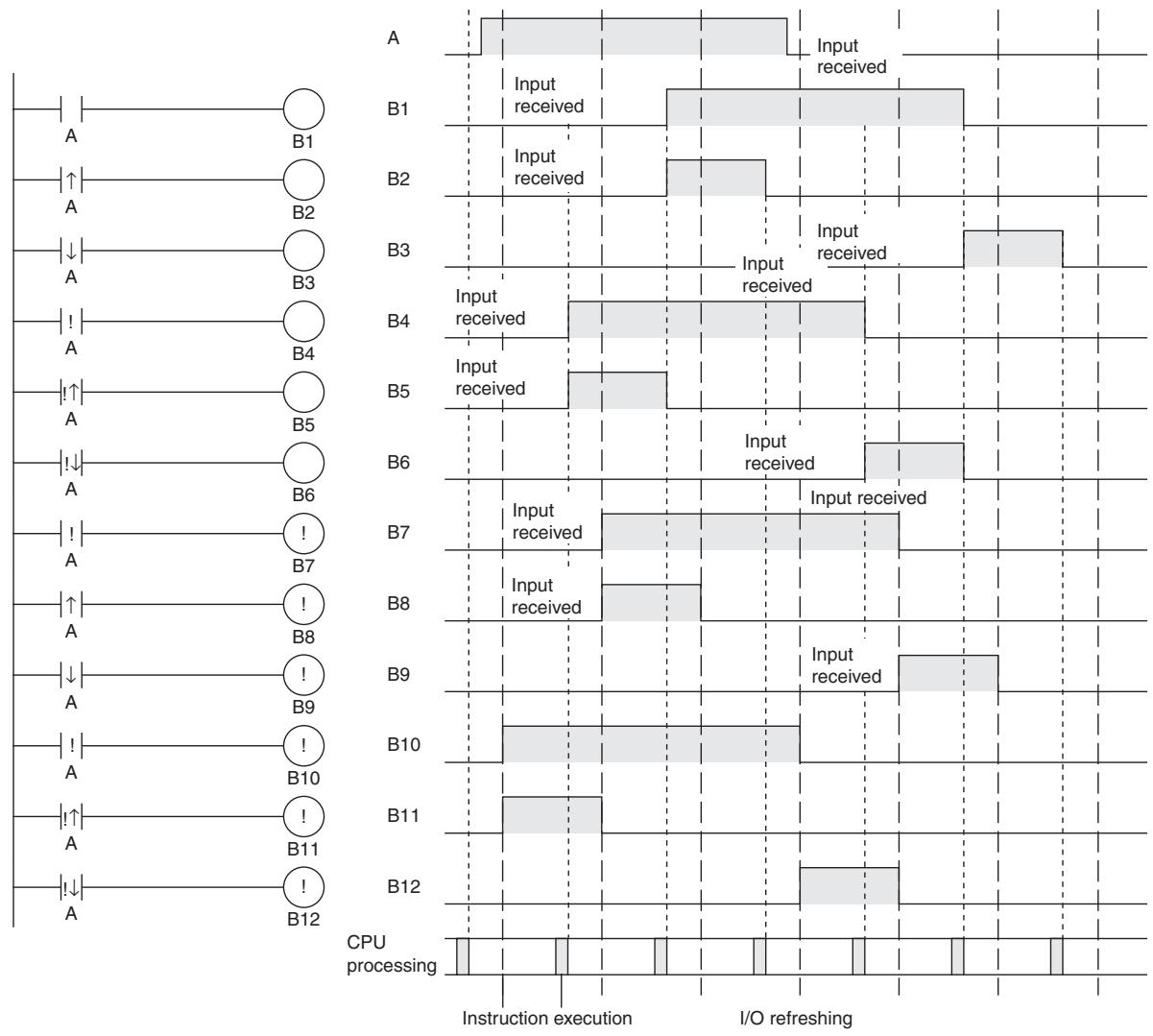
Operation Timing for I/O Instructions
The following chart shows the differences in the timing of instruction operations for a program configured from LD and OUT.
LD/LD NOT
| Instruction | Mnemonic | Variations | Function code | Function |
| LOAD | LD | @LD, %LD, !LD, !@LD, !%LD | --- | Indicates a logical start and creates an ON/OFF execution condition based on the ON/OFF status of the specified operand bit. |
| LOAD NOT | LD NOT | @LD NOT, %LD NOT, ! LD NOT, !@LD NOT, !%LD NOT | --- | Indicates a logical start and creates an ON/OFF execution condition based on the reverse of the ON/OFF status of the specified operand bit. |
| Symbol | LD | LD NOT | ||
| Bus bar | Starting point of block | Bus bar | Starting point of block | |
Applicable Program Areas
| Area | Step program areas | Subroutines | Interrupt tasks |
| Usage | OK | OK | OK |
Operands
| Operand | Description | Data type | Size |
| --- | --- | BOOL | --- |
-Operand Specifications
| Area | Word addresses | Indirect DM addresses | Constants | CF | Pulse bits | TR bits | |||||||
| CIO | WR | HR | AR | T | C | DM | @DM | *DM | |||||
| LD | OK | OK | OK | OK | OK | OK | --- | --- | --- | --- | OK | OK | OK |
| LD NOT | --- | ||||||||||||
Flags
There are no flags affected by this instruction.
Function
LD
LD is used for the first normally open bit from the bus bar or for the first normally open bit of a logic block. If there is no immediate refreshing specification, the specified bit in I/O memory is read. If there is an immediate refreshing specification, the status of the CPU Unit's built-in input terminal is read and used.
- LD NOT
LD NOT is used for the first normally closed bit from the bus bar, or for the first normally closed bit of a logic block. If there is no immediate refreshing specification, the specified bit in I/O memory is read and reversed. If there is an immediate refreshing specification, the status of the CPU Unit's built-in input terminal is read, reversed, and used.
Hint
-
LD/LD NOT is used in the following circumstances as an instruction for indicating a logical start.
-
When directly connecting to the bus bar.
-
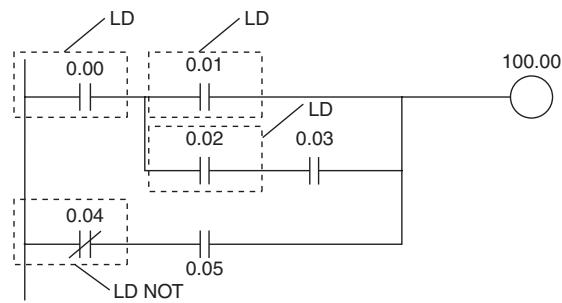
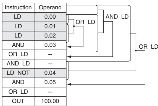
When logic blocks are connected by AND LD or OR LD, i.e., at the beginning of a logic block. The AND LOAD and OR LOAD instructions are used to connect in series or in parallel logic blocks beginning with LD or LD NOT.
-
At least one LOAD or LOAD NOT instruction is required for the execution condition when output-related instructions cannot be connected directly to the bus bar. If there is no LOAD or LOAD NOT instruction, a programming error will occur with the program check by the Peripheral Device.
- When logic blocks are connected by AND LOAD or OR LOAD instructions, the total number of AND LOAD/OR LOAD instructions must match the total number of LOAD/LOAD NOT instructions minus 1. If they do not match, a programming error will occur. For details, refer to AND LOAD: AND LD and OR LOAD: OR LD.
Precautions
- Differentiate up (@) or differentiate down (%) can be specified for LD. If differentiate up (@) is specified, the execution condition is turned ON for one cycle only after the status of the operand bit goes from OFF to ON. If differentiate down (%) is specified, the execution condition is turned ON for one cycle only after the status of the operand bit goes from ON to OFF.
- Immediate refreshing (!) can be specified for LD/LD NOT. An immediate refresh instruction updates the status of the built-in input bit just before the instruction is executed from the CPU Unit.
- For LD, it is possible to combine immediate refreshing and up or down differentiation (@ or!%). If either of these is specified, the input is refreshed from the Basic Input Unit just before the instruction is executed and the execution condition is turned ON for one cycle only after the status goes from OFF to ON, or from ON to OFF.
Sample program
AND/AND NOT
| Instruction | Mnemonic | Variations | Function code | Function |
| AND | AND | @AND, %AND, !AND, !@AND, !%AND | --- | Takes a logical AND of the status of the specified operand bit and the current execution condition. |
| AND NOT | AND NOT | @AND NOT, %AND NOT, !AND NOT, !@AND NOT, !%AND NOT | --- | Reverses the status of the specified operand bit and takes a logical AND with the current execution condition. |
| Symbol | AND | AND NOT |
| —|— | —|— |
Applicable Program Areas
| Area | Step program areas | Subroutines | Interrupt tasks |
| Usage | OK | OK | OK |
Operands
| Operand | Description | Data type | Size |
| --- | --- | BOOL | --- |
-Operand Specifications
| Area | Word addresses | Indirect DM addresses | Constants | CF | Pulse bits | TR bits | |||||||
| CIO | WR | HR | AR | T | C | DM | @DM | *DM | |||||
| AND | OK | OK | OK | OK | OK | OK | --- | --- | --- | --- | OK | OK | --- |
| AND NOT | |||||||||||||
Flags
There are no flags affected by this instruction.
Function
AND
AND is used for a normally open bit connected in series. AND cannot be directly connected to the bus bar, and cannot be used at the beginning of a logic block. If there is no immediate refreshing specification, the specified bit in I/O memory is read. If there is an immediate refreshing specification, the status of the CPU Unit's built-in input terminal is read.
AND NOT
AND NOT is used for a normally closed bit connected in series. AND NOT cannot be directly connected to the bus bar, and cannot be used at the beginning of a logic block. If there is no immediate refreshing specification, the specified bit in I/O memory is read. If there is an immediate refreshing specification, the status the CPU Unit's built-in input terminals is read.
Precautions
- Differentiate up (@) or differentiate down (%) can be specified for AND. If differentiate up (@) is specified, the execution condition is turned ON for one cycle only after the status of the operand bit goes from OFF to ON. If differentiate down (%) is specified, the execution condition is turned ON for one cycle only after the status of the operand bit goes from ON to OFF.
- Immediate refreshing (!) can be specified for AND/AND NOT. An immediate refresh instruction updates the status of the built-in input bit just before the instruction is executed from the CPU Unit.
- For AND, it is possible to combine immediate refreshing and up or down differentiation (@ or!%). If either of these is specified, the input is refreshed from the Basic Input Unit just before the instruction is executed and the execution condition is turned ON for one cycle only after the status goes from OFF to ON, or from ON to OFF.
Sample program
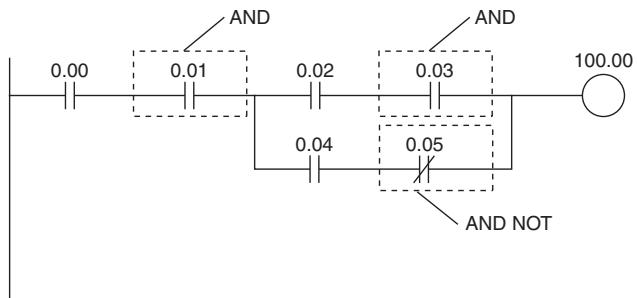
| Instruction | Operand |
| LD | 0.00 |
| AND | 0.01 |
| LD | 0.02 |
| AND | 0.03 |
| LD | 0.04 |
| AND NOT | 0.05 |
| OR LD | -- |
| AND LD | -- |
| OUT | 100.00 |
OR/OR NOT
| Instruction | Mnemonic | Variations | Function code | Function |
| OR | OR | @OR, %OR, !OR, !@OR, !%OR | --- | Takes a logical OR of the ON/OFF status of the specified operand bit and the current execution condition. |
| OR NOT | OR NOT | @OR NOT, %OR NOT, !OR NOT, !@OR NOT, !%OR NOT | --- | Reverses the status of the specified bit and takes a logical OR with the current execution condition. |
| Symbol | OR | OR NOT |
| Bus bar | Bus bar |
Applicable Program Areas
| Area | Step program areas | Subroutines | Interrupt tasks |
| Usage | OK | OK | OK |
Operands
| Operand | Description | Data type | Size |
| --- | --- | BOOL | --- |
-Operand Specifications
| Area | Word addresses | Indirect DM addresses | Constants | CF | Pulse bits | TR bits | |||||||
| CIO | WR | HR | AR | T | C | DM | @DM | *DM | |||||
| OR | OK | OK | OK | OK | OK | OK | --- | --- | --- | --- | OK | OK | --- |
| OR NOT | |||||||||||||
Flags
There are no flags affected by this instruction.
Function
OR
OR is used for a normally open bit connected in parallel. A normally open bit is configured to form a logical OR with a logic block beginning with a LOAD or LOAD NOT instruction (connected to the bus bar or at the beginning of the logic block). If there is no immediate refreshing specification, the specified bit in I/O memory is read. If there is an immediate refreshing specification, the status of the CPU Unit's built-in input terminal is read.
OR NOT
OR NOT is used for a normally closed bit connected in parallel. A normally closed bit is configured to form a logical OR with a logic block beginning with a LOAD or LOAD NOT instruction (connected to the bus bar or at the beginning of the logic block). If there is no immediate refreshing specification, the specified bit in I/O memory is read. If there is an immediate refreshing specification, the status of the CPU Unit's built-in input terminal is read.
Precautions
- Differentiate up (@) or differentiate down (\%) can be specified for OR. If differentiate up (@) is specified, the execution condition is turned ON for one cycle only after the status of the operand bit goes from OFF to ON. If differentiate down (\%) is specified, the execution condition is turned ON for one cycle only after the status of the operand bit goes from ON to OFF.
- Immediate refreshing (!) can be specified for OR/OR NOT. An immediate refresh instruction updates the status of the built-in input bit just before the instruction is executed from the CPU Unit.
- For OR, it is possible to combine immediate refreshing and up or down differentiation (@ or!%). If either of these is specified, the input is refreshed from the Basic Input Unit just before the instruction is executed and the execution condition is turned ON for one cycle only after the status of the oper-and bit goes from OFF to ON, or from ON to OFF.
Sample program
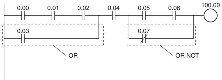
| Instruction | Operand |
| LD | 0.00 |
| AND | 0.01 |
| AND | 0.02 |
| OR | 0.03 |
| AND | 0.04 |
| LD | 0.05 |
| AND | 0.06 |
| OR NOT | 0.07 |
| AND LD | -- |
| OUT | 100.00 |
AND LD/OR LD
| Instruction | Mnemonic | Variations | Function code | Function |
| AND LOAD | AND LD | --- | --- | Takes a logical AND between logic blocks. |
| OR LOAD | OR LD | --- | --- | Takes a logical OR between logic blocks. |
| Symbol | AND LD | OR LD | ||
| Logic block | Logic block | Logic block | Logic block | |
Applicable Program Areas
| Area | Step program areas | Subroutines | Interrupt tasks |
| Usage | OK | OK | OK |
Flags
There are no flags affected by this instruction.
Function
AND LD
AND LD connects in series the logic block just before this instruction with another logic block.
The logic block consists of all the instructions from a LOAD or LOAD NOT instruction until just before the next LOAD or LOAD NOT instruction on the same rungs.
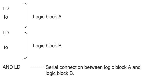
OR LD
OR LD connects in parallel the logic block just before this instruction with another logic block.
The logic block consists of all the instructions from a LOAD or LOAD NOT instruction until just before the next LOAD or LOAD NOT instruction on the same rungs.
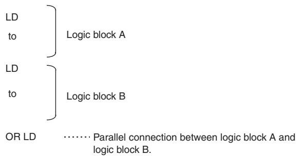
Hint
AND LD
- Three or more logic blocks can be connected in series using this instruction to first connect two of the logic blocks and then to connect the next and subsequent ones in order. It is also possible to continue placing this instruction after three or more logic blocks and connect them together in series.
OR LD
- Three or more logic blocks can be connected in parallel using this instruction to first connect two of the logic blocks and then to connect the next and subsequent ones in order. It is also possible to continue placing this instruction after three or more logic blocks and connect them together in parallel.
Precautions
When a logic block is connected by AND LOAD or OR LOAD instructions, the total number of AND LOAD/OR LOAD instructions must match the total number of LOAD/LOAD NOT instructions minus 1. If they do not match, a programming error will occur.
AND LD
In the following diagram, the two logic blocks are indicated by dotted lines. Studying this example shows that an ON execution condition will be produced when either of the execution conditions in the left logic block is ON (i.e., when either CIO 0.00 or CIO 0.01 is ON) and either of the execution conditions in the right logic block is ON (i.e., when either CIO 0.02 is ON or CIO 0.03 is OFF).
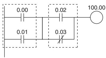
Coding
| Instruction | Operand |
| LD | 0.00 |
| OR | 0.01 |
| LD | 0.02 |
| OR NOT | 0.03 |
| AND LD | --- |
| OUT | 100.00 |
Second LD: Used for first bit of next block connected in series to previous block.
OR LD
The following diagram requires an OR LOAD instruction between the top logic block and the bottom logic block. An ON execution condition would be produced either when CIO 0.00 is ON and CIO 0.01 is OFF or when CIO 0.02 and CIO 0.03 are both ON. The operation of and mnemonic code for the OR LOAD instruction is exactly the same as those for a AND LOAD instruction except that the current execution condition is ORed with the last unused execution condition.
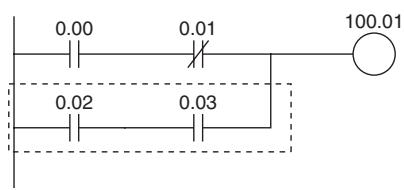
Coding
| Instruction | Operand |
| LD | 0.00 |
| AND NOT | 0.01 |
| LD | 0.02 |
| AND | 0.03 |
| OR LD | --- |
| OUT | 100.01 |
Second LD: Used for first bit of next block connected in series to previous block.
Sample program
AND LD
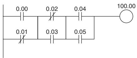
Coding Example (1)
| Instruction | Operand |
| LD | 0.00 |
| OR NOT | 0.01 |
| LD NOT | 0.02 |
| OR | 0.03 |
| AND LD | --- |
| LD | 0.04 |
| OR | 0.05 |
| AND LD | --- |
| . | . |
| . | . |
| OUT | 100.00 |
Coding Example (2)
| Instruction | Operand |
| LD | 0.00 |
| OR NOT | 0.01 |
| LD NOT | 0.02 |
| OR | 0.03 |
| LD | 0.04 |
| OR | 0.05 |
| . | . |
| . | . |
| AND LD | --- |
| AND LD | --- |
| . | . |
| . | . |
| OUT | 100.00 |
- The AND LOAD instruction can be used repeatedly. In programming method (2) above, however, the number of AND LOAD instructions becomes one less than the number of LOAD and LOAD NOT instructions before that.
- In method (2), make sure that the total number of LOAD and LOAD NOT instructions before AND LOAD is not more than eight.
- To use nine or more, program using method (1).
- If there are nine or more with method (2), then a program error will occur during the program check by the Peripheral Device.
OR LD
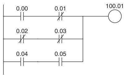
Coding Example (1)
| Instruction | Operand |
| LD | 0.00 |
| AND NOT | 0.01 |
| LD NOT | 0.02 |
| AND NOT | 0.03 |
| OR LD | --- |
| LD | 0.04 |
| AND | 0.05 |
| OR LD | --- |
| . | . |
| . | . |
| OUT | 100.01 |
Coding Example (2)
| Instruction | Operand |
| LD | 0.00 |
| AND NOT | 0.01 |
| LD NOT | 0.02 |
| AND NOT | 0.03 |
| LD | 0.04 |
| AND | 0.05 |
| . | . |
| . | . |
| OR LD | --- |
| OR LD | --- |
| . | . |
| . | . |
| OUT | 100.01 |
- The OR LOAD instruction can be used repeatedly. In programming method (2) above, however, the number of OR LOAD instructions becomes one less than the number of LOAD and LOAD NOT instructions before that.
- In method (2), make sure that the total number of LOAD and LOAD NOT instructions before OR LOAD is not more than eight.
- To use nine or more, program using method (1).
- If there are nine or more with method (2), then a program error will occur during the program check by the Peripheral Device.
NOT
| Instruction | Mnemonic | Variations | Function code | Function |
| NOT | NOT | --- | 520 | Reverses the execution condition. |
| Symbol | NOT |
| —NOT(520) — |
Applicable Program Areas
| Area | Step program areas | Subroutines | Interrupt tasks |
| Usage | OK | OK | OK |
Flags
There are no flags affected by NOT(520).
Function
NOT(520) is placed between an execution condition and another instruction to invert the execution condition.
Precautions
NOT(520) is an intermediate instruction, i.e., it cannot be used as a right-hand instruction. Be sure to program a right-hand instruction after NOT(520).
Sample program
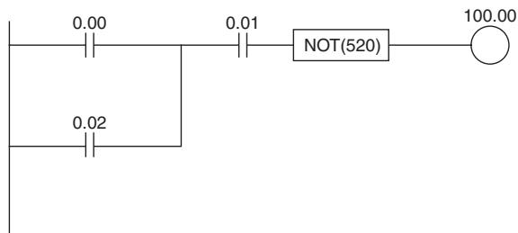
NOT(520) reverses the execution condition in the following example.
| 0.00 | 0.01 | 0.02 | 100.00 |
| 1 | 1 | 1 | 0 |
| 1 | 1 | 0 | 0 |
| 1 | 0 | 1 | 1 |
| 0 | 1 | 1 | 0 |
| 1 | 0 | 0 | 1 |
| 0 | 1 | 0 | 1 |
| 0 | 0 | 1 | 1 |
| 0 | 0 | 0 | 1 |
UP/DOWN
| Instruction | Mnemonic | Variations | Function code | Function |
| CONDITION ON | UP | --- | 521 | UP(521) turns ON the execution condition for the next instruction for one cycle when the execution condition it receives goes from OFF to ON. |
| CONDITION OFF | DOWN | --- | 522 | DOWN(522) turns ON the execution condition for the next instruction for one cycle when the execu-tion condition it receives goes from ON to OFF. |
Applicable Program Areas
| Area | Step program areas | Subroutines | Interrupt tasks |
| Usage | OK | OK | OK |
Flags
There are no flags affected by UP(521) and DOWN(522).
Function
UP
UP(521) is placed between an execution condition and another instruction to turn the execution condition into an up-differentiated condition. UP(521) causes the connecting instruction to be executed just once when the execution condition goes from OFF to ON.
DOWN
DOWN(522) is placed between an execution condition and another instruction to turn the execution condition into a down-differentiated condition. DOWN(522) causes the connecting instruction to be executed just once when the execution condition goes from ON to OFF.
Precautions
- The operation of UP(521) and DOWN(522) depends on the execution condition for the instruction as well as the execution condition for the program section when it is programmed in an interlocked program section, a jumped program section, or a subroutine.
- The operation of UP(521) and DOWN(522) will not be consistent if the same subroutine is executed more than once in the same cycle.
- An subroutine will not be executed while the input condition for the subroutine is OFF. Caution is thus required when using UP(521) and DOWN(522) in a function block definition. For details, refer to information on SBS(091).
Sample program
UP
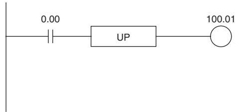
When CIO 0.00 goes from OFF to ON, CIO 100.01 is turned ON for just one cycle.
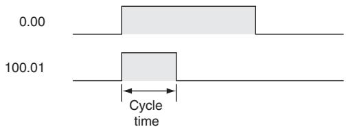
Sequence Output Instructions
OUT/OUT NOT
| Instruction | Mnemonic | Variations | Function code | Function |
| OUTPUT | OUT | !OUT | --- | Outputs the result (execution condition) of the logical processing to the specified bit. |
| OUTPUT NOT | OUT NOT | !OUT NOT | --- | Reverses the result (execution condition) of the logical processing, and outputs it to the specified bit. |
| Symbol | OUT | OUT NOT |
Applicable Program Areas
| Area | Step program areas | Subroutines | Interrupt tasks |
| Usage | OK | OK | OK |
Operands
| Operand | Description | Data type | Size |
| --- | --- | BOOL | --- |
-Operand Specifications
| Area | Word addresses | Indirect DM addresses | Constants | CF | Pulse bits | TR bits | |||||||
| CIO | WR | HR | AR | T | C | DM | @DM | *DM | |||||
| OUT | OK | OK | OK | OK | --- | --- | OK | --- | --- | --- | --- | --- | OK |
| OUT NOT | |||||||||||||
Flags
There are no flags affected by this instruction.
Function
OUT
If there is no immediate refreshing specification, the status of the execution condition (power flow) is written to the specified bit in I/O memory. If there is an immediate refreshing specification, the status of the execution condition (power flow) is also written to the CPU Unit's built-in output terminal in addition to the output bit in I/O memory.
OUT NOT
If there is no immediate refreshing specification, the status of the execution condition (power flow) is reversed and written to a specified bit in I/O memory. If there is an immediate refreshing specification, the status of the execution condition (power flow) is reversed and also written to the CPU Unit's built-in output terminal in addition to the output bit in I/O memory.
Hint
- Immediate refreshing (!) can be specified for OUT and OUT NOT. An immediate refresh instruction updates the status of the built-in output terminal just after the instruction is executed for the CPU Unit, at the same time as it writes the status of the execution condition (power flow) to the specified output bit in I/O memory.
- Difference between SET/RSET and OUT For OUT, the operand bit is turned ON when the input condition turns ON and is turned OFF when the input condition turns OFF. For SET and RSET, the operand bit turns ON or OFF, respectively, when the input condition turns ON and the operand bit does not change when the input condition turns OFF.
Sample program
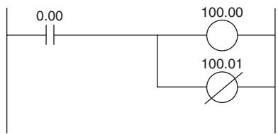
| Instruction | Operand |
| LD | 0.00 |
| OUT | 100.00 |
| OUT NOT | 100.01 |
TR
| Instruction | Mnemonic | Variations | Function code | Function |
| TR Bits | TR | --- | --- | TR bits are used to temporarily retain the ON/OFF status of execution conditions in a program when programming in mnemonic code. |
Function
TR bits are used to temporarily retain the ON/OFF status of execution conditions in a program when programming in mnemonic code. They are not used when programming directly in ladder program form because the processing is automatically executed by the Peripheral Device. The following diagram shows a simple application using two TR bits.
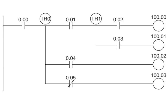
Coding
| Instruction | Operands |
| LD | 0.00 |
| OUT | TR0 |
| AND | 0.01 |
| OUT | TR1 |
| AND | 0.02 |
| OUT | 100.00 |
| LD | TR1 |
| AND | 0.03 |
| OUT | 100.01 |
| LD | TR0 |
| AND | 0.04 |
| OUT | 100.02 |
| LD | TR0 |
| AND NOT | 100.00 |
| OUT | 100.03 |
Relay Address
| Temporary Relay | TR0 to TR15 |
Using TR0 to TR15
- TR0 to TR15 are used only with LOAD and OUTPUT instructions.
- There are no restrictions on the order in which the bit addresses are used.
- Sometimes it is possible to simplify a program by rewriting it so that TR bits are not required. The following diagram shows one case in which a TR bit is unnecessary and one in which a TR bit is required.
In instruction block (1), the ON/OFF status at point A is the same as for output CIO 100.00, so AND 0.01 and OUT 100.01 can be coded without requiring a TR bit. In instruction block (2), the status of the branching point and that of output CIO 100.02 are not necessarily the same, so a TR bit must be used. In this case, the number of steps in the program could be reduced by using instruction block (1) in place of instruction block (2).
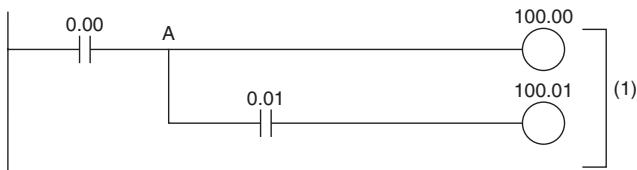
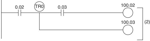
KEEP
| Instruction | Mnemonic | Variations | Function code | Function |
| KEEP | KEEP | !KEEP | 011 | Operates like a latching relay. |
| Symbol | KEEP | ||
| S(SET) | KEEP(011) | R: Bit | |
| R(RESET) | R | ||
Applicable Program Areas
| Area | Step program areas | Subroutines | Interrupt tasks |
| Usage | OK | OK | OK |
Operands
| Operand | Description | Data type | Size |
| R | Bit | BOOL | --- |
-Operand Specifications
| Area | Word addresses | Indirect DM addresses | Constants | CF | Pulse bits | TR bits | |||||||
| CIO | WR | HR | AR | T | C | DM | @DM | *DM | |||||
| R | OK | OK | OK | OK | --- | --- | --- | --- | --- | --- | --- | --- | OK |
Flags
No flags are affected by KEEP(011).
Function
When S turns ON, the designated bit will go ON and stay ON until reset, regardless of whether S stays ON or goes OFF. When R turns ON, the designated bit will go OFF. The relationship between execution conditions and KEEP(011) bit status is shown below on the right.
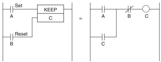
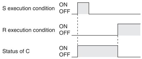
Hint
- KEEP(011) has an immediate refreshing variation (IKEEP(011)). When a CPU Unit built-in output bit has been specified for R in a !KEEP(011) instruction, any changes to R will be refreshed when !KEEP(011) is executed and reflected immediately in the output bit.
- KEEP(011) operates like the self-maintaining bit, but a self-maintaining bit programmed with KEEP(011) requires one less instruction.
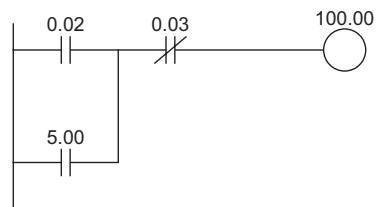
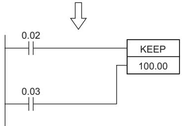
Self-maintaining bits programmed with KEEP(011) will maintain status even in an interlock program section, unlike the self-maintaining bit programmed without KEEP(011).
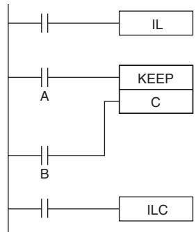
Output bit C will maintain its previous status in an interlock.
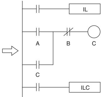
Output bit C will be turned OFF in an interlock.
- KEEP(011) can be used to create flip-flops as shown below.
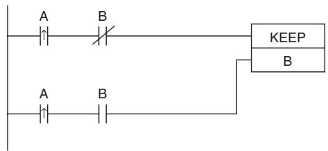
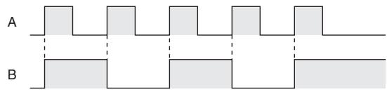
- If a holding bit is used for R, the bit status will be retained even during a power interruption. KEEP(011) can thus be used to program bits that will maintain status after restarting the PLC following a power interruption. An example of this that can be used to produce a warning display following a system shutdown for an emergency situation is shown below.
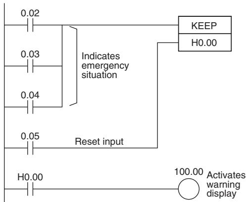
- The status of I/O Area bits can be retained in the event of a power interruption by turning ON the IOM Hold Bit and setting IOM Hold Bit Hold in the PLC Setup. In this case, I/O Area bits used in KEEP(011) will maintain status after restarting the PLC following a power interruption, just like holding bits. Be sure to restart the PLC after changing the PLC Setup; otherwise the new settings will not be used.
Precautions
- If S and R are ON simultaneously, the reset input takes precedence.
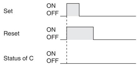
- The set input (S) cannot be received while R is ON.
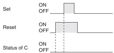
- Never use an input bit in a normally closed condition on the reset (R) for KEEP(011) when the input device uses an AC power supply. The delay in shutting down the PLC's DC power supply (relative to the AC power supply to the input device) can cause the operand bit of KEEP(011) to be reset. This situation is shown on the right.
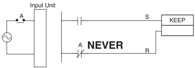
Sample program
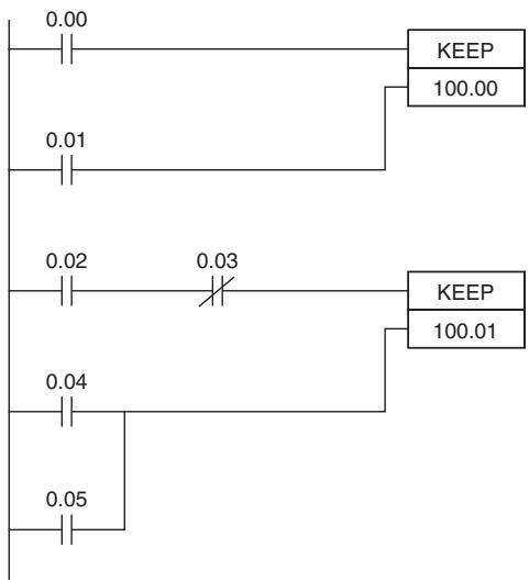
When CIO 0.00 goes ON in the left example, CIO 100.00 is turned ON. CIO 100.00 remains ON until CIO 0.01 goes ON.
When CIO 0.02 goes ON and CIO 0.03 goes OFF in the left example, CIO 100.01 is turned ON. CIO 100.01 remains ON until CIO 0.04 or CIO 0.05 goes ON.
Coding
| Instruction | Operand |
| LD | 0.00 |
| LD | 0.01 |
| KEEP (011) | 100.00 |
| LD | 0.02 |
| AND NOT | 0.03 |
| LD | 0.04 |
| OR | 0.05 |
| KEEP (011) | 100.01 |
Note KEEP(011) is input in different orders on in ladder and mnemonic form. In ladder form, input the set input, KEEP(011), and then the reset input. In mnemonic form, input the set input, the reset input, and then KEEP(011).
DIFU
| Instruction | Mnemonic | Variations | Function code | Function |
| DIFFERENTIATE UP | DIFU | !DIFU | 013 | DIFU(013) turns the designated bit ON for one cycle when the execution condition goes from OFF to ON (rising edge). |
| Symbol | DIFU |
| — | — DIFU(013) — R: Bit |
Applicable Program Areas
| Area | Step program areas | Subroutines | Interrupt tasks |
| Usage | OK | OK | OK |
Operands
| Operand | Description | Data type | Size |
| R | Bit | BOOL | --- |
- Operand Specifications
| Area | Word addresses | Indirect DM addresses | Constants | CF | Pulse bits | TR bits | |||||||
| CIO | WR | HR | AR | T | C | DM | @DM | *DM | |||||
| R | OK | OK | OK | OK | --- | --- | --- | --- | --- | --- | --- | --- | --- |
Flags
No flags are affected by DIFU(013).
Function
When the execution condition goes from OFF to ON, DIFU(013) turns R ON. When DIFU(013) is reached in the next cycle, R is turned OFF.
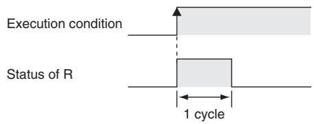
Hint
- UP(521) can be used to execute an instruction for just one cycle when the execution condition goes from OFF ON.
- DIFU(013) has immediate refreshing variation (!DIFU(013)). When a CPU Unit built-in output bit has been specified for R in this instruction, any changes to R will be refreshed when the instruction is executed and reflected immediately in the output bit.
Precautions
- The operation of DIFU(013) depends on the execution condition for the instruction itself as well as the execution condition for the program section when it is programmed in an interlocked program section, a jumped program section, or a subroutine.
- An subroutine will not be executed while the input condition for the subroutine is OFF. Caution is thus required when using DIFU(013) in a function block definition. For details, refer to information on SBS(091).
- The operation of DIFU(013) will not be consistent if the same subroutine is executed more than once in the same cycle.
Sample program
When CIO 0.00 goes from ON to OFF in the following example, CIO 100.00 is turned ON for one cycle.

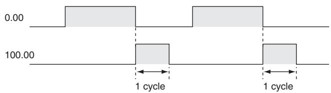
DIFD
| Instruction | Mnemonic | Variations | Function code | Function |
| DIFFERENTIATE DOWN | DIFD | !DIFD | 014 | DIFD(014) turns the designated bit ON for one cycle when the execution condition goes from ON to OFF (falling edge). |
| Symbol | DIFD |
| — | — DIFD(014) — R: Bit |
Applicable Program Areas
| Area | Step program areas | Subroutines | Interrupt tasks |
| Usage | OK | OK | OK |
Operands
| Operand | Description | Data type | Size |
| R | Bit | BOOL | --- |
- Operand Specifications
| Area | Word addresses | Indirect DM addresses | Constants | CF | Pulse bits | TR bits | |||||||
| CIO | WR | HR | AR | T | C | DM | @DM | *DM | |||||
| B | OK | OK | OK | OK | --- | --- | --- | --- | --- | --- | --- | --- | --- |
Flags
No flags are affected by DIFD(014).
Function
When the execution condition goes from ON to OFF, DIFD(014) turns R ON. When DIFD(014) is reached in the next cycle, R is turned OFF.
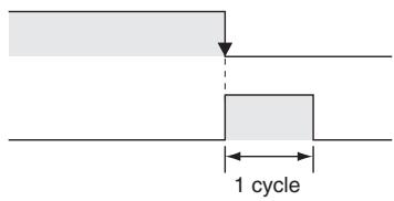
Execution condition
Status of R
Hint
- DOWN(522) can be used to execute an instruction for just one cycle when the execution condition goes from ON OFF.
- The operation of DIFD(014) depends on the execution condition for the instruction itself as well as the execution condition for the program section when it is programmed in an interlocked program section, a jumped program section, or a subroutine.
- DIFD(014) has immediate refreshing variation (IDIFD(014)). When a CPU Unit built-in output bit has been specified for R in this instruction, any changes to R will be refreshed when the instruction is executed and reflected immediately in the output bit.
Precautions
- The operation of DIFD(014) will not be consistent if the same function block instance is executed more than once in the same cycle.
- An subroutine will not be executed while the input condition for the subroutine is OFF. Caution is thus required when using DIFD(014) in a function block definition. For details, refer to information on SBS(091).
Sample program
When CIO 0.00 goes from ON to OFF in the following example, CIO 100.00 is turned ON for one cycle.
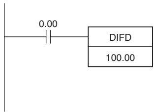
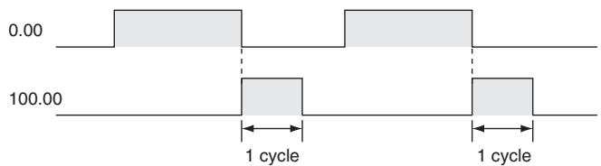
SET/RSET
| Instruction | Mnemonic | Variations | Function code | Function |
| SET | SET | @SET, %SET, !SET, !@SET, !%SET | --- | SET turns the operand bit ON when the execution condition is ON. After this, the specified contact will remain ON regardless of ON/OFF of the input condition. |
| RESET | RSET | @RSET, %RSET, !RSET, !@RSET, !%RSET | --- | RSET turns the operand bit OFF when the execution condition is ON. After this, the specified contact will remain OFF regardless of ON/OFF of the input condition. |
| Symbol | SET | RSET | ||
| SET R | R: Bit | SET R | R: Bit | |
Applicable Program Areas
| Area | Step program areas | Subroutines | Interrupt tasks |
| Usage | OK | OK | OK |
Operands
| Operand | Description | Data type | Size |
| R | Bit | BOOL | --- |
- Operand Specifications
| Area | Word addresses | Indirect DM addresses | Constants | CF | Pulse bits | TR bits | |||||||
| CIO | WR | HR | AR | T | C | DM | @DM | *DM | |||||
| R | OK | OK | OK | OK | --- | --- | --- | --- | --- | --- | --- | --- | --- |
Flags
No flags are affected by SET and RSET.
Function
- SET
SET turns the operand bit ON when the execution condition is ON, and does not affect the status of the operand bit when the execution condition is OFF. Use RSET to turn OFF a bit that has been turned ON with SET.
Execution condition of SET
Status of R
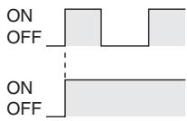
- RSET
RSET turns the operand bit OFF when the execution condition is ON, and does not affect the status of the operand bit when the execution condition is OFF. Use SET to turn ON a bit that has been turned OFF with RSET.
Execution condition of RSET
Status of R
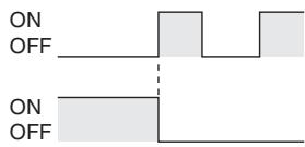
Hint
- Differences between OUT/OUT NOT and SET/RSET
The operation of SET differs from that of OUT because the OUT instruction turns the operand bit OFF when its execution condition is OFF. Likewise, RSET differs from OUT NOT because OUT NOT turns the operand bit ON when its execution condition is OFF. For OUT, the operand bit is turned ON when the input condition turns ON and is turned OFF when the input condition turns OFF. For SET and RSET, the operand bit turns ON or OFF, respectively, when the input condition turns ON and the operand bit does not change when the input condition turns OFF.

- The set and reset inputs for a KEEP(011) instruction must be programmed with the instruction, but the SET and RSET instructions can be programmed completely independently. Furthermore, the same bit may be used as the operand in any number of SET or RSET instructions.
- SET and RSET have immediate refreshing variations (!SET and !RSET). When a CPU Unit built-in output bit has been specified for R in one of these instructions, any changes to R will be refreshed when the instruction is executed and reflected immediately in the output bit.
If external output is specified for R by !SET (or !RSET), R will be OUT-refreshed as soon as it turns ON (or OFF) (when the instruction is executed). R, which turned ON (or OFF), will remain ON (or OFF) as normal until a RSET instruction (or SET instruction) is executed.
Precautions
- SET and RSET cannot be used to set and reset timers and counters. When SET or RSET is programmed between IL(002) and ILC(003) or JMP(004) and JME(005), the status of the specified bit will not be changed if the program section is interlocked or jumped.
SETA/RSTA
| Instruction | Mnemonic | Variations | Function code | Function |
| MULTIPLE BIT SET | SETA | @SETA | 530 | SETA(530) turns ON the specified number of consecutive bits. |
| MULTIPLE BIT RESET | RSTA | @RSTA | 531 | RSTA(531) turns OFF the specified number of consecutive bits. |
| Symbol | SETA | RSTA | ||
| SETA(530) | RSTA(531) | |||
| D | D: Beginning word | D | D: Beginning word | |
| N1 | N1: Beginning bit | N1 | N1: Beginning bit | |
| N2 | N2: Number of bits | N2 | N2: Number of bits | |
Applicable Program Areas
| Area | Step program areas | Subroutines | Interrupt tasks |
| Usage | OK | OK | OK |
Operands
| Operand | Description | Data type | Size |
| D | Beginning Word | UINT | Variable |
| N1 | Beginning Bit | UINT | 1 |
| N2 | Number of Bits | UINT | 1 |
- Operand Specifications
| Area | Word addresses | Indirect DM addresses | Constants | CF | Pulse bits | TR bits | |||||||
| CIO | WR | HR | AR | T | C | DM | @DM | *DM | |||||
| D | OK | OK | OK | OK | OK | OK | OK | OK | OK | --- | --- | --- | --- |
| N1,N2 | OK | ||||||||||||
Flags
| Operand | Description | Data type |
| Error Flag | P_ER | ON if N1 is not within the specified range of 0000 to 000F (&0 to &15).OFF in all other cases. |
Function
- SETA
SETA(530) turns ON N2 bits, beginning from bit N1 of D, and continuing to the left (more-significant bits). All other bits are left unchanged. (No changes will be made if N2 is set to 0.)
Bits turned ON by SETA(530) can be turned OFF by any other instructions, not just RSTA(531).
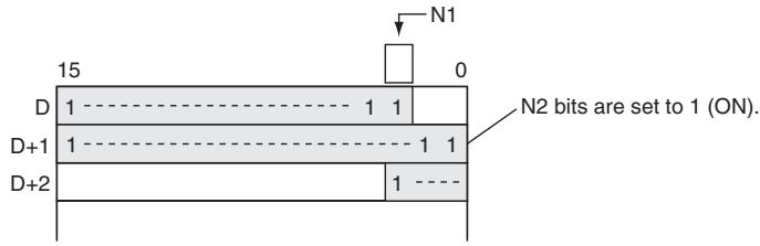
RSTA
RSTA(531) turns OFF N2 bits, beginning from bit N1 of D, and continuing to the left (more-significant bits). All other bits are left unchanged. (No changes will be made if N2 is set to 0.)
Bits turned OFF by RSTA(531) can be turned ON by any other instructions, not just SETA(530).
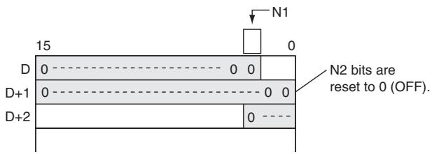
Hint
- SETA
- SETA(530) can be used to turn ON bits in data areas that are normally accessed by words only, such as the DM areas.
RSTA
- RSTA(531) can be used to turn OFF bits in data areas that are normally accessed by words only, such as the DM areas.
Sample program
- SETA
When CIO 0.00 is turned ON in the following example, the 20 bits (0014 hexadecimal) beginning with bit 5 of CIO 100 are turned ON.

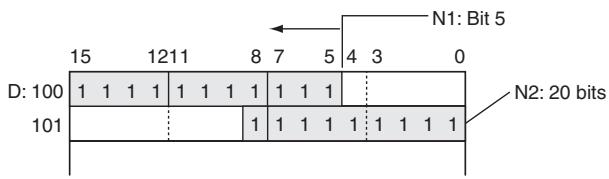
RSTA
When CIO 0.00 is turned ON in the following example, the 20 bits (0014 hexadecimal) beginning with bit 3 of CIO 100 are turned OFF.
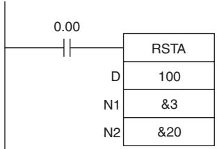
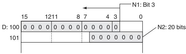
SETB/RSTB
| Instruction | Mnemonic | Variations | Function code | Function |
| SINGLE BIT SET | SETB | @SETB, !SETB, !@SETB | 532 | SETB(532) turns ON the specified bit. |
| SINGLE BIT RESET | RSTB | @RSTB, !RSTB, !@RSTB | 533 | RSTB(533) turns OFF the specified bit. |
| Symbol | SETB | RSTB | ||
| SETB(532)D N | D: Word addressN: Bit number | SETB(533)D N | D: Word addressN: Bit number | |
Applicable Program Areas
| Area | Step program areas | Subroutines | Interrupt tasks |
| Usage | OK | OK | OK |
Operands
| Operand | Description | Data type | Size |
| D | Word address | UINT | 1 |
| N | Bit number | UINT | 1 |
- Operand Specifications
| Area | Word addresses | Indirect DM addresses | Constants | CF | Pulse bits | TR bits | |||||||
| CIO | WR | HR | AR | T | C | DM | @DM | *DM | |||||
| D | OK | OK | OK | OK | OK | OK | OK | OK | OK | --- | --- | --- | --- |
| N | OK | ||||||||||||
Flags
| Operand | Description | Data type |
| Error Flag | P_ER | ON if N is not within the specified range of 0000 to 000F (&0 to &15).OFF in all other cases. |
Function
- SETB
SETB(532) turns ON bit N of word D when the execution condition is ON. The status of the bit is not affected when the execution condition is OFF.
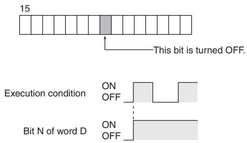
RSTB
RSTB(533) turns OFF bit N of word D when the execution condition is ON. The status of the bit is not affected when the execution condition is OFF. (Use SETB(532) to turn ON the bit.)
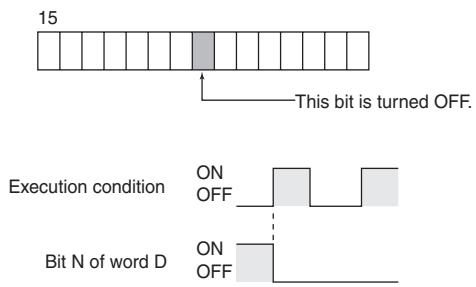
Hint
- Differences between SET/RSET and SETB(532)/RSTB(533)
The instructions operate in the same way when the specified bit is in the CIO, W, H, or A Area.
The SETB(532) and RSTB(533) instructions can control bits in the DM Areas, unlike SET and RSET.
- The set and reset inputs for a KEEP(011) instruction must be programmed with the instruction, but the SETB(532) and RSTB(533) instructions can be programmed completely independently. Furthermore, the same bit may be used as the operand in any number of SETB(532) and RSTB(533) instructions.
Precautions
- Bits turned ON by SETB(532) can be turned OFF by any other instruction, not just RSTB(533).
- Bits turned OFF by RSTB(533) can be turned ON by any other instruction, not just SETB(532).
- SETB(532) and RSTB(533) cannot set/reset timers and counters.
- When SETB(532) or RSTB(533) is programmed between IL(002) and ILC(003) or JMP(004) and JME(005), the status of the specified bit will not be changed if the program section is interlocked or jumped, i.e., when the interlock condition or jump condition is OFF.
- SETB(532) and RSTB(533) have immediate refreshing variations (!SETB(532) and !RSTB(533)). When a CPU Unit built-in output bit has been specified in one of these instructions, any changes to the specified bit will be refreshed when the instruction is executed and reflected immediately in the output bit.
- When a CPU Unit built-in output is specified for bit address N of word D by !SETB (or !RSTB instruction), bit address N of word D which turned ON (or OFF) will be OUT-refreshed at that point (when the instruction is executed). Bit address N of word D which was turned ON (or OFF) remains ON (or OFF) as normal until an RSTB instruction (or SETB instruction) is executed.
Sample program
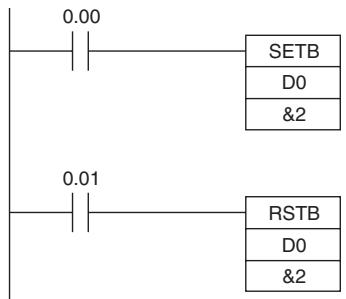
Bit 02 of D0 is turned ON when CIO 0.00 is ON.
Bit 02 of D0 is turned OFF when CIO 0.01 is ON.
Sequence Control Instructions
Overview of Interlock Instructions
- Interlock Instructions
The following instruction combinations can be used to interlock outputs in a program section.
- INTERLOCK and INTERLOCK CLEAR (IL(002) and IL(003))
- MULTI-INTERLOCK DIFFERENTIATION HOLD and MULTI-INTERLOCK CLEAR (MILH(517) and MILC(519))*
Note MILH(517) holds the status of the Differentiation Flag, so differentiated instructions that were interlocked are executed after the interlock is cleared.
- MULTI-INTERLOCK DIFFERENTIATION RELEASE and MULTI-INTERLOCK CLEAR (MILR(518) and MILC(519))*
Note MILR(518) does not hold the status of the Differentiation Flag, so differentiated instructions that were interlocked are not executed after the interlock is cleared.
- Differences between Interlocks and Multiple Interlocks
Regular interlocks (IL(002) and IL(003)) cannot be nested, but multiple interlocks (MILH(517), MILR(518), and MILC(519)) can be nested. Ladder programming can be simplified by nesting multiple interlocks, as shown in the following diagram.
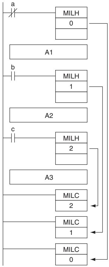
Interlocks with MILH and MILC
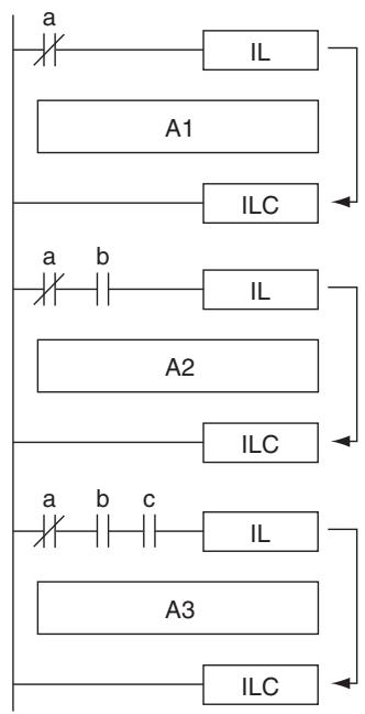
Interlocks with IL and ILC
- Differences between MILH(517) and MILR(518)
Differentiated instructions (DIFU, DIFD, or instructions with a @ or % prefix) operate differently in interlocks created with MILH(517) and MILR(518).
The operation of differentiated instructions in an interlock created with MILH(517) is identical to the operation in an interlock created with IL(002).
For details, refer to MULTI-INTERLOCK DIFFERENTIATION HOLD, MULTI-INTERLOCK DIFFERENTIATION RELEASE, and MULTI-INTERLOCK CLEAR: MILH(517), MILR(518), and MILC(519).
Precautions
Do not combine interlocks created with different interlock instructions (IL-ILC, MILH-MILC, and MILR-MILC). The interlocks may not operate properly if different interlock methods are used together. For details on combining instructions, refer to MULTI-INTERLOCK DIFFERENTIATION HOLD, MULTI-INTERLOCK DIFFERENTIATION RELEASE, and MULTI-INTERLOCK CLEAR: MILH(517), MILR(518), and MILC(519).
For example, an MILH(517) instruction cannot be inserted between IL(002) and IL(003).
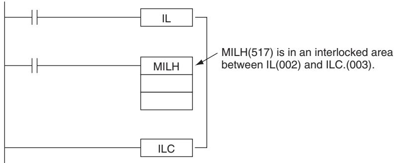
Note The different interlocks (IL-ILC, MILH-MILC, and MILR-MILC) can be used together as long as the interlocked program sections do not overlap.
For example, all three interlock methods can be used without overlapping, as shown in the following diagram.

- Differences between Interlocks and Jumps
The following table shows the differences between interlocks (created with IL(002)/ILC(003), MILH(517)/MILC(519), or MILR(518)/MILC(519)) and jumps created with JMP(004)/JME(005).
| Item | Treatment in IL(002)/ILC(003), MILH(517)/MILC (519), or MILR(518)/MILC (519) | Treatment in JMP(004)/JME(005) |
| Instruction execution | Except OUT, OUT NOT, and timer instructions, all instructions are not executed. | No instructions are executed. |
| Output status in instructions | Except for outputs in OUT, OUT NOT, and timer instructions, all outputs retain their previous status. | All outputs retain their previous status. |
| Bits in OUT, OUT NOT | OFF | All outputs retain their previous status. |
| Status of timer instructions (except (TTIM(087), TTIMX(555), MTIM(543), and MTIMX(554)) | Reset | Operating timers (TIM, TIMX(550), TIMH(015), TIMHX(551), TMHH(540), TMHHX(552) only) continue timing because the PVs are updated even when the timer instruction is not being executed. |
END
| Instruction | Mnemonic | Variations | Function code | Function |
| END | END | --- | 001 | Indicates the end of a program. |
| Symbol | END |
| END(001) |
Applicable Program Areas
| Area | Step program areas | Subroutines | Interrupt tasks |
| Usage | Not allowed | Not allowed | OK |
Flags
There are no flags affected by this instruction.
Function
END(001) completes the execution of a program for that cycle. No instructions written after END(001) will be executed.
Precautions
- Always place END(001) at the end of each program. A programming error will occur if there is not an END(001) instruction in the program.
NOP
| Instruction | Mnemonic | Variations | Function code | Function |
| NO OPERATION | NOP | --- | 000 | This instruction has no function. |
| Symbol | NOP |
| (There is no ladder symbol associated with NOP(000).) |
Applicable Program Areas
| Area | Step program areas | Subroutines | Interrupt tasks |
| Usage | OK | OK | OK |
Flags
No flags are affected by NOP(000).
Function
- No processing is performed for NOP(000), but this instruction can be used to set aside lines in the program where instructions will be inserted later.
- NOP(000) can only be used with mnemonic displays, not with ladder programs.
Hint
- When the instructions are inserted later, there will be no change in program addresses.
IL/ILC
| Instruction | Mnemonic | Variations | Function code | Function |
| INTERLOCK | IL | --- | 002 | Interlocks all outputs between IL(002) and ILC(003) when the execution condition for IL(002) is OFF. |
| INTERLOCK CLEAR | ILC | --- | 003 | Indicates the end of the interlock range. |
| Symbol | IL | ILC | ||
| —| IL(002) —| | —| ILC(003) —| | |||
Applicable Program Areas
| Area | Step program areas | Subroutines | Interrupt tasks |
| Usage | Not allowed | OK | OK |
Flags
There are no flags affected by this instruction.
Function
When the execution condition for IL(002) is OFF, the outputs for all instructions between IL(002) and ILC(003) are interlocked. When the execution condition for IL(002) is ON, the instructions between IL(002) and ILC(003) are executed normally.
The following table shows the treatment of various outputs in an interlocked section between IL(002) and ILC(003).
| Instruction | Treatment | |
| Bits specified in OUT, OUT NOT | OFF | |
| TIM, TIMX(550), TIMH(015), TIMHX(551), TMHH(540), TMHHX(552), TIML(542), and TIMXL(553) | Completion Flag | OFF (reset) |
| PV | Time set value (reset) | |
| Bits/words specified in all other instructions (See note.) | Retain previous status. | |
Note Bits and words in all other instructions including TTIM(087), TTIMX(555), SET, RSET, CNT, CNTX(546), CNTR(012), CNTRX(548), SFT, and KEEP(011) retain their previous status.
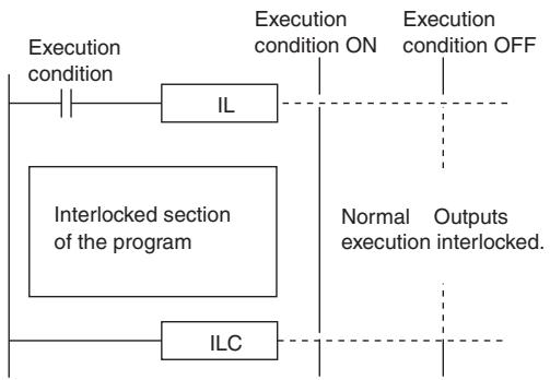
Hint
- If there are bits which you want to remain ON in an interlocked program section, set these bits to ON with SET just before IL(002).
- It is often more efficient to switch a program section with IL(002) and ILC(003). When several processes are controlled with the same execution condition, it takes fewer program steps to put these processes between IL(002) and ILC(003).
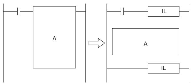
Precautions
- The cycle time is not shortened when a section of the program is interlocked because the interlocked instructions are executed internally.
- In general, IL(002) and ILC(003) are used in pairs, although it is possible to use more than one IL(002) with a single ILC(003) as shown in the following diagram. If IL(002) and ILC(003) are not paired, an error message will appear when the program check is performed but the program will be executed properly.
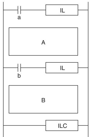
| Execution condition | Program section | ||
| a | b | A | B |
| OFF | ON | Interlocked | Interlocked |
| OFF | OFF | Interlocked | Interlocked |
| ON | OFF | Not interlocked | Interlocked |
| ON | ON | Not interlocked | Not interlocked |
- IL(002) and ILC(003) cannot be nested, as in the following diagram. (Use MILH(517)/MILR(518) and MILC(519) when it is necessary to nest interlocks.)
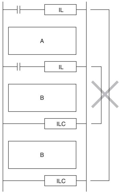
Operation of Differentiated Instructions
If there is a differentiated instruction (DIFU, DIFD, or instruction prefixed by @ or %) between IL(002) and ILC(003) instructions, that instruction will be executed when the interlock is cleared if the differentiation condition of the instruction is satisfied by means of a change in the input condition between starting and clearing of the interlock.
Example:
When a DIFFERENTIATE UP (DIFU(013)) instruction is used and the input condition is OFF when the interlock starts and ON when the interlock is cleared, the DIFFERENTIATE UP (DIFU(013)) instruction will be executed when the interlock is cleared.

Reference:
An IL(002) instruction operates in the same way as an MILH(517) instruction in relation to differentiated instruction operation.
Timing Chart
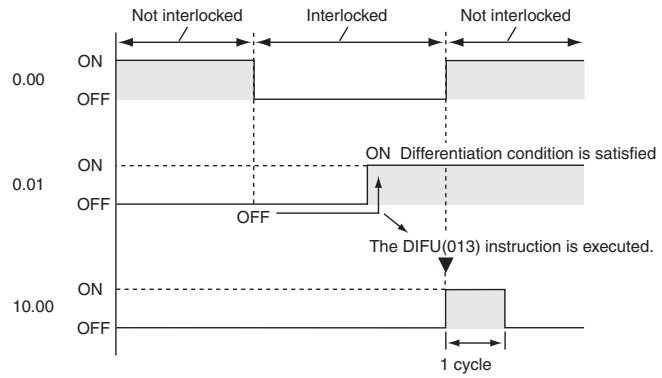
Sample program
When CIO 0.00 is OFF in the right example, all outputs between IL(002) and ILC(003) are interlocked. When CIO 0.00 is ON in the right example, the instructions between IL(002) and ILC(003) are executed normally.
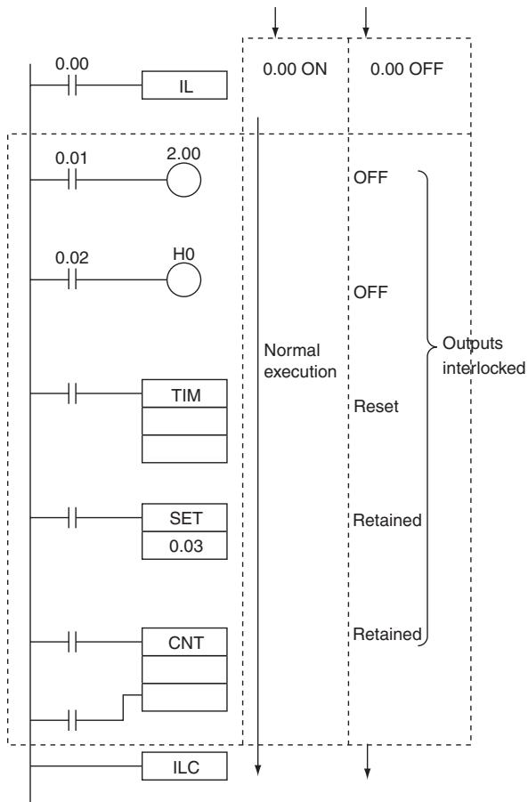
MILH/MILR/MILC
| Instruction | Mnemonic | Variations | Function code | Function |
| MULTI-INTERLOCK DIFFER-ENTIATION HOLD | MILH | --- | 517 | Interlocks all outputs between MILH(517) and MILC(519) when the execution condition for MILH(517) is OFF. |
| MULTI-INTERLOCK DIFFER-ENTIATION RELEASE | MILR | --- | 518 | Interlocks all outputs between MILR(518) and MILC(519) when the execution condition for MILR(518) is OFF. |
| MULTI-INTERLOCK CLEAR | MILC | --- | 519 | Indicates the end of a multi-interlock range by means of an MILH or MILR instruction with the same interlock number. |
| Symbol | MILH | MILR | MILC | |||
| — | — | — | — | — | — | |
| MILH(517) | — | — | MILR(518) | |||
| N | N | N | ||||
| D | D | N: Interlock Number | ||||
| N: Interlock Number | N: Interlock Number | |||||
| D: Interlock Status Bit | D: Interlock Status Bit | |||||
Applicable Program Areas
| Area | Step program areas | Subroutines | Interrupt tasks |
| Usage | Not allowed | OK | OK |
Operands
| Operand | Description | Data type | Size |
| N | Interlock number | -- | 1 |
| D | Interlock status bit | BOOL | -- |
N: Interlock Number
The interlock number must be between 0 and 15. Match the interlock number of the MILH(517) (or MILR(518)) instruction with the same number in the corresponding MILC(519) instruction.
The interlock numbers can be used in any order.
D: Interlock Status Bit
- ON when the program section is not interlocked.
- OFF when the program section is interlocked.
When the interlock is engaged, the Interlock Status Bit can be force-set to release the interlock. Conversely, when the interlock is not engaged, the Interlock Status Bit can be force-reset to engage the interlock.
- Operand Specifications
| Area | Word addresses | Indirect DM addresses | Constants | CF | Pulse bits | TR bits | |||||||
| CIO | WR | HR | AR | T | C | DM | @DM | *DM | |||||
| N | --- | --- | --- | --- | --- | --- | --- | --- | --- | OK | --- | --- | --- |
| D | OK | OK | OK | OK | --- | ||||||||
Flags
| Name | Label | Operation |
| Error Flag | P_ER | OFF |
Function
When the execution condition for MILH(517) (or MILR(518)) with interlock number N is OFF, the outputs for all instructions between that MILH(517)/MILR(518) instruction and the next MILC(519) with interlock number N are interlocked.
When the execution condition for MILH(517) (or MILR(518)) with interlock number N is ON, the instructions between that MILH(517)/MILR(518) instruction and the next MILC(519) with interlock number N are executed normally.
- Interlock Status
The following table shows the treatment of various outputs in an interlocked section between MILH(517)/MILR(518) instruction and the next MILC(519).
| Instruction | Treatment | |
| Bits specified in OUT, OUT NOT | OFF | |
| TIM, TIMX(550), TIMH(015),TIMHX(551), TMHH(540),TMHHX(552), TIML(542), andTIMXL(553) | Completion Flag | OFF (reset) |
| PV | Time set value (reset) | |
| Bits/words specified in all other instructions (See note.) | Retain previous status. | |
Note Bits and words in all other instructions including TTIM(087), TTIMX(555), SET, RSET, CNT, CNTX(546), CNTR(012), CNTRX(548), SFT, and KEEP(011) retain their previous status.
The MILH(517)/MILR(518) instruction turns OFF the Interlock Status Bit (operand D) when the interlock is in engaged and turns ON the bit when the interlock is not engaged. Consequently, the Interlock Status Bit can be monitored to check whether or not the interlock for a given interlock number is engaged.

- Nesting
Interlocks are nested when an interlocked program section (MILH(517)/MILR(518) and MILC(519) combination) is placed within another interlocked program section (MILH(517)/MILR(518) and MILC(519) combination). Interlocks can be nested up to 16 levels.
Nesting can be used for the following kinds of applications.
Example 1
Interlocking the entire program with one condition and interlocking a part of the program with another condition (1 nesting level)
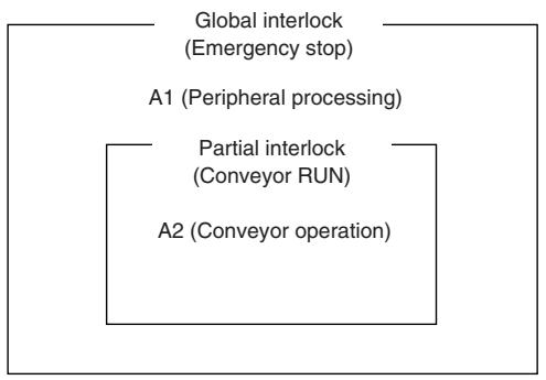
- A1 and A2 are interlocked when the Emergency Stop Button is ON.
- A2 is interlocked when Conveyor RUN is OFF.
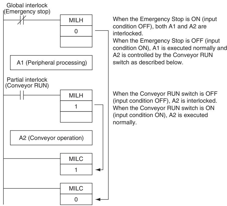
Example 2
Interlocking the entire program with one condition and interlocking two overlapping parts of the program with other conditions (2 nesting levels)
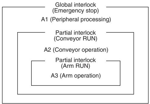
- A1, A2, and A3 are interlocked when the Emergency Stop Button is ON.
- A2 and A3 are interlocked when Conveyor RUN is OFF.
- A3 is interlocked when Arm RUN is OFF.
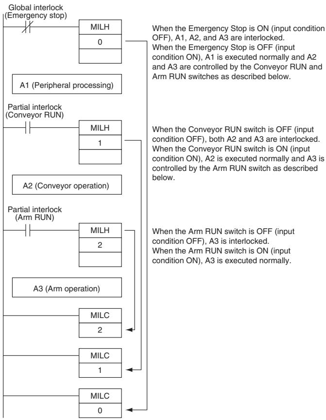
- Differences between MILH(517) and MILR(518)
Differentiated instructions (DIFU, DIFD, or instructions with a @ or % prefix) operate differently in interlocks created with MILH(517) and MILR(518).
When a program section is interlocked with MILR(518), a differentiated instruction will not be executed when the interlock is cleared even if the differentiation condition was activated during the interlock (comparing the status of the execution condition when the interlock started to its status when the interlock was cleared).
When a program section is interlocked with MILH(517), a differentiated instruction will be executed when the interlock is cleared if the differentiation condition was activated during the interlock (comparing the status of the execution condition when the interlock started to its status when the interlock was cleared).
| Instruction | Operation of Differentiated Instructions |
| MILH(517) MULTI-INTERLOCK DIFFER-ENTIATION HOLD | A differentiated instruction (DIFU, DIFD, or instruction with a @ or % prefix) will be executed after the interlock is cleared if the differentiation condition of the instruction was established while the instruction was interlocked. (The status of the execution condition when the interlock started is compared to its status when the interlock was cleared.) |
| MILR(518) MULTI-INTERLOCK DIFFER-ENTIATION RELEASE | A differentiated instruction (DIFU, DIFD, or instruction with a @ or % prefix) will not be executed after the interlock is cleared even if the differentiation condition of the instruction was established while the instruction was interlocked. |
- Operation of Differentiated Instructions in an MILH(517) Interlock
If there is a differentiated instruction (DIFU, DIFD, or instruction with a @ or % prefix) between MILH(517) and the corresponding MILC(519), that instruction will be executed after the interlock is cleared if the differentiation condition of the instruction was established.
In the same way, a differentiated instruction will be executed if its execution condition is established at the same time that the interlock is started or cleared.
Many other conditions in the program may cause the differentiation condition to be reset even if it was established during the interlock. In this case, the differentiation instruction will not be executed when the interlock is cleared.
Example
When a DIFFERENTIATE UP (DIFU(013)) instruction is being used and the input condition is OFF when the interlock starts and ON when the interlock is cleared, DIFU(013) will be executed when the interlock is cleared. (Differentiated instructions operate the same in the MILH(517) interlock as they would in an IL(002) interlock.)
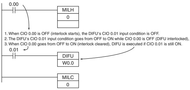
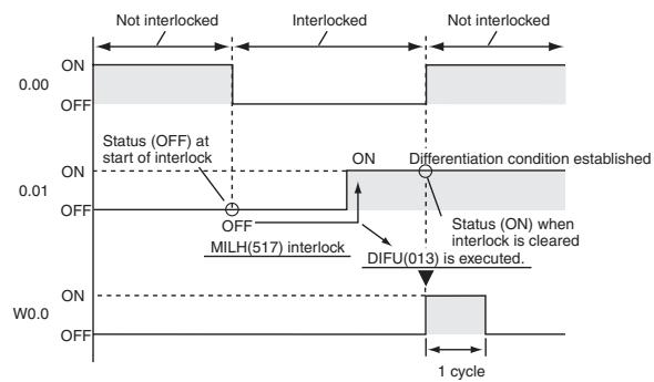
Timing chart
- Operation of Differentiated Instructions in an MILR(518) Interlock
If there is a differentiated instruction (DIFU, DIFD, or instruction with a @ or % prefix) between MILR(518) and the corresponding MILC(519), that instruction will not be executed after the interlock is cleared even if the differentiation condition of the instruction was established.
In the same way, a differentiated instruction will not be executed if its execution condition is established at the same time that the interlock is started or cleared.
Example
When a DIFFERENTIATE UP (DIFU(013)) instruction is being used and the input condition is OFF when the interlock starts and ON when the interlock is cleared, DIFU(013) will not be executed when the interlock is cleared.
Timing chart
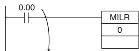
1. When CIO 0.00 is OFF (interlock starts), the DIFU's CIO 0.01 input condition is OFF.
2. The DIFU's CIO 0.01 input condition goes from OFF to ON while CIO 0.00 is OFF (DIFU interlocked),
3. When CIO 0.00 goes from OFF to ON (interlock cleared), DIFU is not executed even though CIO 0.01 is still ON.

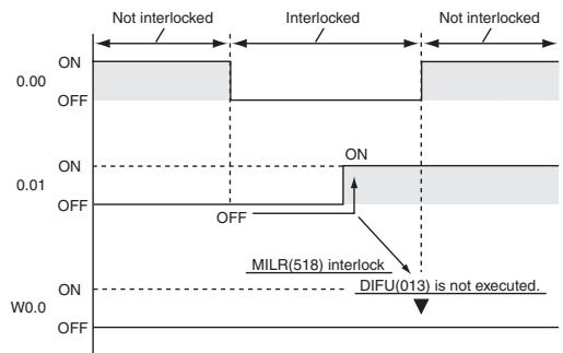
- Controlling Interlock Status from a Programming Device
An interlock can be engaged or released manually by force-resetting or force-setting the Interlock Status Bit (specified with operand D of MILH(517) and MILR(518)) from a Programming Device. The forced status of the Interlock Status Bit has priority and overrides the interlock status calculated by program execution.
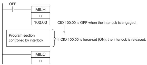
Force-set: Releases the interlock.
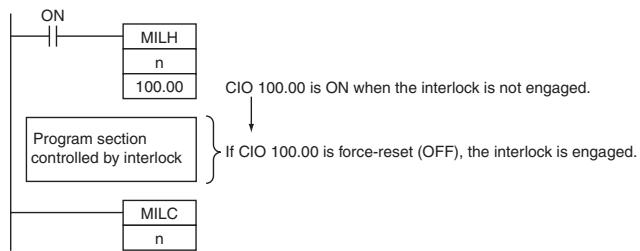
Force-reset: Engages the interlock.
Hint
- The cycle time is not shortened when a section of the program is interlocked by MILH(517) or MILR(518) because the interlocked instructions are executed internally.
- When nesting interlocks, assign interlock numbers so that the nested program section does not exceed the outer program section.
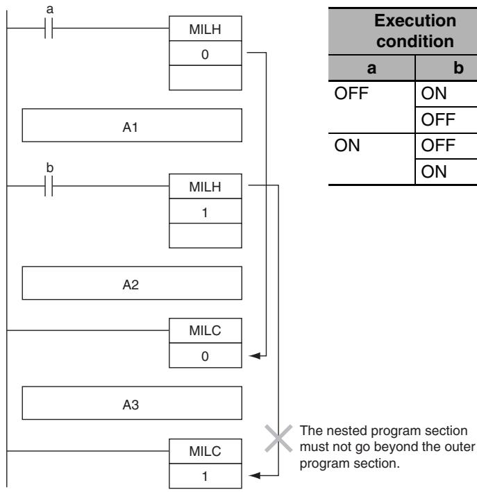
The nested program section must not go beyond the outer program section.
- Other instructions can be input between the MILC(519) instructions, as shown in the following diagram.
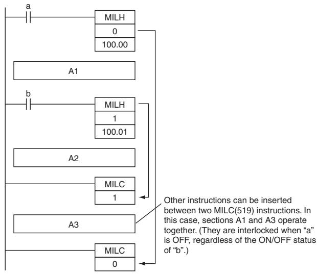
- If there is an ILC(003) instruction between an MILH(517) and MILC(519) pair, the program section between MILH(517) and ILC(003) will be interlocked.
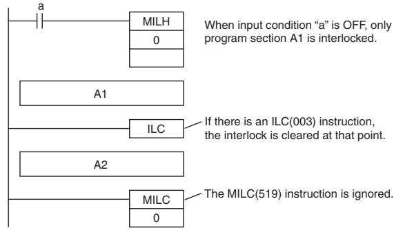
- If there is an ILC(003) instruction between an MILR(518) and MILC(519) pair, the ILC(003) instruction will be ignored and the full program section between MILR(518) and MILC(519) will be interlocked.
- If there is another MILH(517) or MILR(518) instruction with the same interlock number between an MILH(517) and MILC(519) pair and the first MILH(517) instruction's interlock is engaged, the second MILH(517)/MILR(518) will not operate.
- If there is another MILH(517) or MILR(518) instruction with the same interlock number between an MILH(517) and MILC(519) pair and the first MILH(517) instruction's interlock is not engaged, the second MILH(517)/MILR(518) will operate normally.
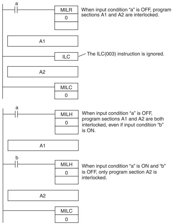
Note The MILR(518) interlocks operate in the same way if there is another MILH(517) or MILR(518) instruction with the same interlock number between an MILR(518) and MILC(519) pair.
- If there is an MILC(519) instruction with a different interlock number between an MILH(517)/MILR(518) and MILC(519) pair, that MILC(519) instruction will be ignored.
- If there is an MILH(517) instruction between an IL(002) and ILC(003) pair and the IL(002) interlock is engaged, the MILH(517) instruction has no effect. In this case, the program section between IL(002) and ILC(003) will be interlocked. If the IL(002) interlock is not engaged and the MILH(517) instruction's execution condition (b in this case) is OFF, the program section between MILH(517) and ILC(003) will be interlocked.
- If there is an MILC(519) instruction between an IL(002) and ILC(003) pair, that MILC(519) instruction will be ignored and the entire program section between IL(002) and ILC(003) will be interlocked.
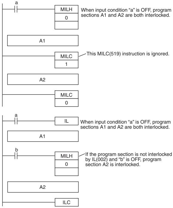
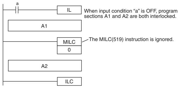
- Program operation can be switched more efficiently by using interlocks with MILH(517) or MILR(518). Instead of switching processing with compound conditions, insert an MILH(517) or MILR(518) instruction before each process and an MILC(519) instruction after each process.
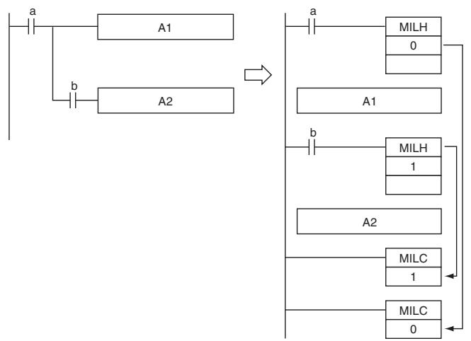
- Unlike the IL(002) interlocks, MILH(517) and MILR(518) interlocks can be nested, so the operation of similar programs will be different if MILH(517) or MILR(518) is used instead of ILC(002).
- Program with MILH(517)/MILC(519) Interlocks
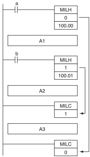
| Execution condition | Program section | |||
| a | b | A1 | A2 | A3 |
| OFF | ON | Interlocked | Interlocked | Not interlocked |
| OFF | ||||
| ON | OFF | Not interlocked | Interlocked | Not interlocked |
| ON | ON | Not interlocked | Not interlocked | Not interlocked |
- Program with IL(002)/ILC(003) Interlocks
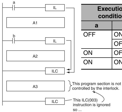
| Execution condition | Program section | |||
| a | b | A1 | A2 | A3 |
| OFF | ON | Interlocked | Interlocked | Not interlocked (Not controlled by the IL(002)/ILC(003) interlock.) |
| OFF | ||||
| ON | OFF | Not interlocked | Interlocked | |
| ON | ON | Not interlocked | Not interlocked | |
- If there are bits which you want to remain ON in a program section interlocked by MILH(517) or MILR(518), set these bits to ON with SET just before the MILH(517) or MILR(518) instruction.
Sample program
When W0.00 and W0.01 are both ON, the instructions between MILH(517) with interlock number 0 and MILC(519) with interlock number 0 are executed normally.
When W0.00 is OFF, the instructions between MILH(517) with interlock number 0 and MILC(519) with interlock number 0 are interlocked.
When W0.00 is ON and W0.01 are OFF, the instructions between MILH(517) with interlock number 1 and MILC(519) with interlock number 1 are interlocked. The other instructions are executed normally.
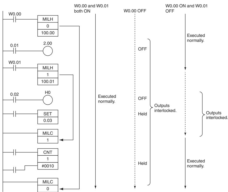
JMP/CJP/JME
| Instruction | Mnemonic | Variations | Function code | Function |
| JUMP | JMP | --- | 004 | When the execution condition for JMP(004) is OFF, program execution jumps directly to the first JME(005) in the program with the same jump number. |
| CONDITIONAL JUMP | CJP | --- | 510 | When the execution condition for CJP(510) is ON, program execution jumps directly to the first JME(005) in the program with the same jump number. |
| JUMP END | JME | --- | 005 | Indicates the end position of a jump by JMP or CJP instruction. |
| Symbol | JMP | JME | ||
| JMP(004)N | N:Jump number | JME(005)N | N: Jump number | |
| CJP | ||||
| CJP(510)N | N: Jump number | |||
Applicable Program Areas
| Area | Step program areas | Subroutines | Interrupt tasks |
| Usage | Not allowed | OK | OK |
Operands
| Operand | Description | Data type | Size |
| N | Jump number | UINT | 1 |
N: Jump Number
The jump number must be 0000 to 007F (&0 to &127 decimal).
-Operand Specifications
| Area | Word addresses | Indirect DM addresses | Constants | CF | Pulse bits | TR bits | ||||||||
| CIO | WR | HR | AR | T | C | DM | @DM | *DM | ||||||
| JMP/CJP | N | OK | OK | OK | OK | OK | OK | OK | OK | OK | OK | --- | --- | --- |
| JME | N | --- | --- | --- | --- | --- | --- | --- | --- | --- | ||||
Flags
JMP/CJP
| Name | Label | Operation |
| Error Flag | P_ER | ON if N is not within the specified range of 0000 to 007F.ON if there is a JMP(004) in the program without a JME(005) with the same jump number.OFF in all other cases. |
JME
There are no flags affected by this instruction.
Function
JMP
When the execution condition for JMP(004) is ON, no jump is made and the program is executed consecutively as written.
When the execution condition for JMP(004) is OFF, program execution jumps directly to the first JME(005) in the program with the same jump number. The instructions between JMP(004) and JME(005) are not executed, so the status of outputs between JMP(004) and JME(005) is maintained. In block programs, the instructions between JMP(004) and JME(005) are skipped regardless of the status of the execution condition.
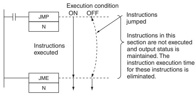
CJP
When the execution condition for CJP(510) is OFF, no jump is made and the program is executed consecutively as written.
When the execution condition for CJP(510) is ON, program execution jumps directly to the first JME(005) in the program with the same jump number.
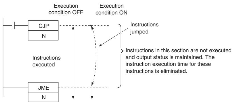
Hint
- Because all of instructions between JMP(004)/CJP(510) and JME(005) are skipped when the execution condition for JMP(004) is OFF, the cycle time is reduced by the total execution time of the skipped instructions. In contrast, processing time equivalent to NOP(000) processing is required for instructions between JMP0(515) and JME0(516), so the cycle time is not reduced as much with those jump instructions.
- The following table compares the various jump instructions.
| Item | JMP(004)JME(005) | CJP(510)JME(005) |
| Execution condition for jump | OFF | ON |
| Number allowed | 128 | |
| Instruction processing when jumped | Not executed. | |
| Instruction execution time when jumped | None | |
| Status of outputs (bits and words) when jumped | Bits and words maintain their previous status. | |
| Status of operating timers when jumped | Operating timers continue timing. | |
| Processing in block programs | Always jump. | Jump when ON. |
Precautions
-
All of the outputs (bits and words) in jumped instructions retain their previous status. Operating timers (TIM, TIMX(550), TIMH(015), TIMHX(551), TMHH(540) and TMHHX(552)) continue timing because the PVs are updated even when the timer instruction is not being executed.
-
When there are two or more JME(005) instructions with the same jump number, only the instruction with the lower address will be valid. The JME(005) with the higher program address will be ignored.
- CJP(510) jumps to the first JME(005) when the execution condition is ON and JMP(004) jumps to the first JME(005) when the execution condition is OFF.
- When JME(005) precedes JMP(004)/CJP(510) in the program, the instructions between JME(005) and JMP(004)/CJP(510) will be executed repeatedly as long as the execution condition for JMP(004)/CJP(510) is OFF. A Cycle Time Too Long error will occur if the execution condition is not turned ON or END(001) is not executed within the maximum cycle time.
- The operation of DIFU(013), DIFD(014), and differentiated instructions is not dependent solely on the status of the execution condition when they are programmed between JMP(004)/CJP(510) and JME(005). When DIFU(013), DIFD(014), or a differentiated instruction is executed in an jumped section immediately after the execution condition for the JMP(004)/CJP(510) has gone ON, the execution condition for the DIFU(013), DIFD(014), or differentiated instruction will be compared to the execution condition that existed before the jump became effective (i.e., before the execution condition for JMP(004) went OFF).
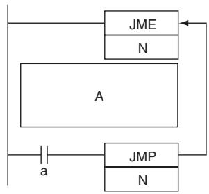
Program section A is executed repeatedly as long as execution condition a is OFF.
Sample program
When CIO 0.00 is OFF in the right example, the instructions between JMP(004) and JME(005) are not executed and the outputs maintain their previous status.
When CIO 0.00 is ON in the right example, the instructions between JMP(004) and JME(005) are executed normally.
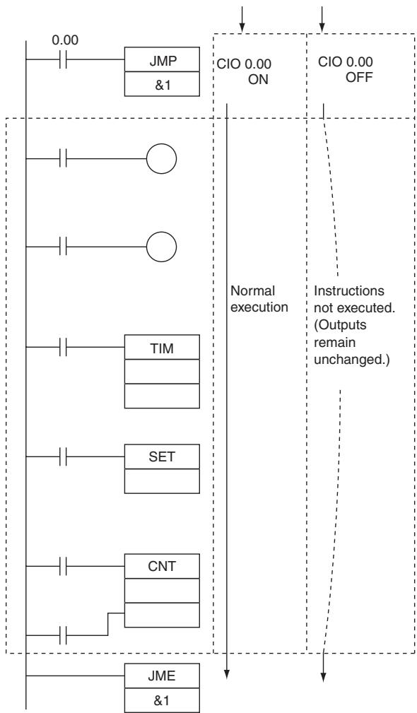
FOR/NEXT
| Instruction | Mnemonic | Variations | Function code | Function |
| --- | FOR | --- | 512 | The instructions between FOR(512) and NEXT(513) are repeated a specified number of times. |
| NEXT | --- | 513 |
| Symbol | FOR | NEXT | |
| FOR(512)N | N: Number of loops | —NEXT(513) | |
Applicable Program Areas
| Area | Step program areas | Subroutines | Interrupt tasks |
| Usage | --- | OK | OK |
Operands
| Operand | Description | Data type | Size |
| N | Number of loops | UINT | 1 |
N: Number of loops
The number of loops must be 0000 to FFFF (0 to 65,535 decimal).
-Operand Specifications
| Area | Word addresses | Indirect DM addresses | Constants | CF | Pulse bits | TR bits | |||||||
| CIO | WR | HR | AR | T | C | DM | @DM | *DM | |||||
| N | OK | OK | OK | OK | OK | OK | OK | OK | OK | OK | --- | --- | --- |
Flags
| Name | Label | Operation |
| Error Flag | P_ER | ON if more than 15 loops are nested. OFF in all other cases. |
| Equals Flag | P_EQ | OFF |
| Negative Flag | P_N | OFF |
Function
The instructions between FOR(512) and NEXT(513) are executed N times and then program execution continues with the instruction after NEXT(513). The BREAK(514) instruction can be used to cancel the loop.
If N is set to 0, the instructions between FOR(512) and NEXT(513) are processed as NOP(000) instructions.
Loops can be used to process tables of data with a minimum amount of programming.
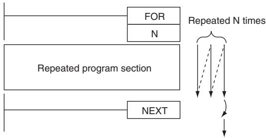
Hint
There are two ways to repeat a program section until a given execution condition is input.
FOR-NEXT Loop with BREAK
Start a FOR-NEXT loop with a maximum of N repetitions. Program BREAK(514) within the loop with the desired execution condition. The loop will end before N repetitions if the execution condition is input.
JME(005)-JMP(004) Loop
Program a loop with JME(005) before JMP(004). The instructions between JME(005) and JMP(004) will be executed repeatedly as long as the execution condition for JMP(004) is OFF. (A Cycle Time Too Long error will occur if the execution condition is not turned ON or END(001) is not executed within the maximum cycle time.)
Precautions
- Program FOR(512) and NEXT(513) in the same task. Execution will not be repeated if these instructions are not in the same task.
- If a loop repeats in one cycle and a differentiated instruction is used in the FOR-NEXT loop, that instruction will be executed only once. It is not executed the number of loops.
UP(521),DOWN(522)
- DIFU(013),DIFD(014)
- Differentiated up instruction(Differentiation variation:@)
Differentiated down instruction(Differentiation variation:%)
FOR-NEXT loops can be nested up to 15 levels.
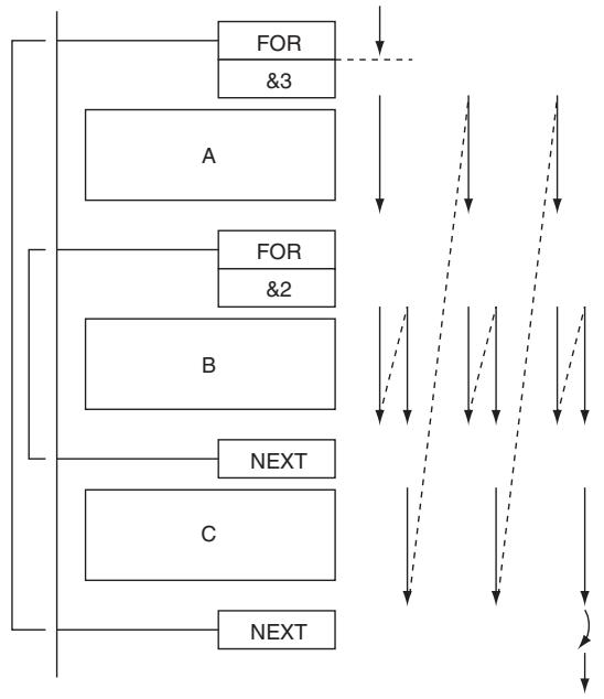
In the example above, program sections A, B, and C are executed as follows:
- Use BREAK(514) to escape from a FOR-NEXT loop. Several BREAK(514) instructions (the number of levels nested) are required to escape from nested loops.
- The remaining instructions in the loop after BREAK(514) are processed as NOP(000) instructions.
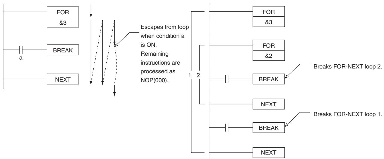
- A jump instruction such as JMP(004) may be executed within a FOR-NEXT loop, but do not jump beyond the FOR-NEXT loop.
-
The following instructions cannot be used within FOR-NEXT loops:
-
STEP DEFINE and STEP START: STEP(008)/SNXT(009)
Sample program
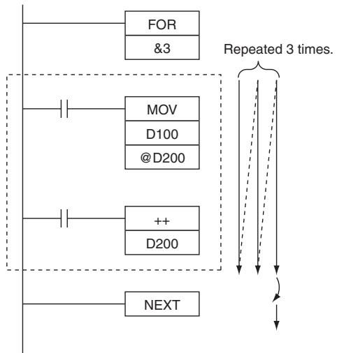
In the left example, the looped program section transfers the content of D100 to the address indicated in D200 and then increments the content of D200 by 1.
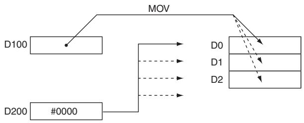
BREAK
| Instruction | Mnemonic | Variations | Function code | Function |
| BREAK LOOP | BREAK | --- | 514 | Programmed in a FOR-NEXT loop to cancel the execution of the loop for a given execution condition. The remaining instructions in the loop are processed as NOP(000) instructions. |
| Symbol | BREAK |
| —| BREAK(514) —| |
Applicable Program Areas
| Area | Step program areas | Subroutines | Interrupt tasks |
| Usage | --- | OK | OK |
Flags
| Name | Label | Operation |
| Error Flag | P_ER | OFF |
| Equals Flag | P_EQ | OFF |
| Negative Flag | P_N | OFF |
Function
Program BREAK(514) between FOR(512) and NEXT(513) to cancel the FOR-NEXT loop when BREAK(514) is executed. When BREAK(514) is executed, the rest of the instructions up to NEXT(513) are processed as NOP(000).
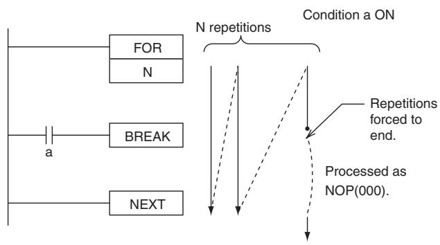
Precautions
- A BREAK(514) instruction cancels only one loop, so several BREAK(514) instructions (the number of levels nested) are required to escape from nested loops.
BREAK(514) can be used only in a FOR-NEXT loop.
Timer and Counter Instructions
Refresh Methods for Timer/Counter PV
- Overview
There are two PV refresh methods for instructions related to timer/counters, "BCD" and "BINARY".
| Method | Description | Setting range | Set value |
| BCD | Sets the timer set value in BCD. | 0~9.999 | #0000~9999 |
| Binary | Sets the timer set value in BINARY. | 0~65.535 | &0~65535 or #0000~FFFF |
The PLC Setup for all of the timer/counter-related instructions. The refresh method is valid also when setting an SV indirectly (i.e., using the contents of memory word). (That is, the contents of the addressed word is taken as either BCD or binary data according to the refresh method that is set.)
- Applicable Instructions
| Classification | Instruction | Mnemonic | |
| BCD | Binary | ||
| Timer/counter instructions | HUNDRED-MS TIMER | TIM | TIMX(550) |
| TEN-MS TIMER | TIMH(015) | TIMHX(551) | |
| ONE-MS TIMER | TMHH(540) | TMHHX(552) | |
| ACCUMULATIVE TIMER | TTIM(087) | TTIMX(555) | |
| LONG TIMER | TIML(542) | TIMLX(553) | |
| COUNTER | CNT | CNTX(546) | |
| REVERSIBLE COUNTER | CNTR(012) | CNTRX(548) | |
| RESET TIMER/COUNTER | CNR(545) | CNRX(547) | |
- Setting method for PV refresh
BCD and binary PV refreshing can both be used in the same project. The setting of the PV refresh method in the PLC Setup will be ignored.
Basic Timer Specifications
| Item | TIM/TIMX(550) | TIMH(015)/TIMHX(551) | TMHH(540)/TMHHX(552) | TTIM(087)/TTIMX(555) | TIML(542)/TIMLX(553) | |
| Timing method | Decrementing | Decrementing | Decrementing | Incrementing | Decrementing | |
| Timing units | 100 ms | 10 ms | 1 ms | 100 ms | 100 ms | |
| Maximum SV | TIM: 999.9 sTIMX: 6,553.5 s | TIMH: 99.99 sTIMHX: 655.35 s | TMHH: 9.999 sTMHHX: 65.535 s | TTIM: 999.9 sTTIMX: 6,553.5 s | TIML:115 daysTIMLX: 49,710 days | |
| Outputs/instruction | 1 | 1 | 1 | 1 | 1 | |
| Timer numbers | Used | Used | Used | Used | Not used | |
| Completion Flag refreshing | When the instruction is executed | When the instruction is executed | When the instruction is executed | When the instruction is executed | When the instruction is executed | |
| Timer PV refreshing(See note) | When the instruction is executed | When the instruction is executed | When the instruction is executed | When the instruction is executed | When the instruction is executed | |
| Value afterreset | Completion Flags | OFF | OFF | OFF | OFF | OFF |
| PVs | SV | SV | SV | 0 | SV | |
- Operating Mode
| Item | TIM/TIMX(550) | TIMH(015)/TIMHX(551) | TMHH(540)/TMHHX(552) | TTIM(087)/TTIMX(555) | TIML(542)/TIMLX(553) | |
| Operating mode change | PV = 0Completion Flag = OFF | --- | ||||
| Power interrupt/reset | PV = 0Completion Flag = OFF | --- | ||||
| Execution of CNR(545)/CNRX(547) | Binary: PV = FFFF, Completion Flag = OFFBCD: PV = FFFF or 9999, Completion Flag = OFF | Not applicable | ||||
| Operation in jumped program section (JMP(004)-JME(005)) | Operating timers continue timing. | Timer status is maintained. | ||||
| Operation in interlocked program section (IL(002)-ILC(003)) | PV = SVCompletion Flag = OFF | Timer status main-tained. | PV = SVCompletion Flag = OFF | |||
| Forced set | Completion Flag | ON | --- | |||
| PVs | Set to 0. | --- | ||||
| Forced reset | Completion Flags | OFF | --- | |||
| PVs | Reset to SV. | Set to 0. | --- | |||
- Example Timer and Counter Applications
Example 1: Long-term Timers
The following program examples show three ways to create long-term timers with standard TIM and CNT instructions.
1) Two TIM Instructions
In this example, two TIM instructions are combined to make a 30-minute timer.
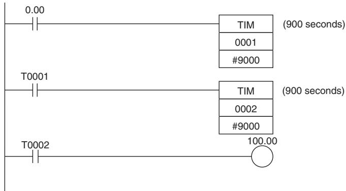
| Instruction | Operands |
| LD | 0.00 |
| TM | 1 |
| #9000 | |
| LD | T0001 |
| TM | 2 |
| #9000 | |
| LD | T000 |
| OUT | 100.00 |
2) TIM and CNT Instructions
In this example, a TIM instruction and a CNT instruction are combined to make a 500-second timer. TIM 0001 generates a pulse every 5 s and CNT 0002 counts these pulses. The set value for this combination is the timer interval × counter SV. In this case, the timer SV would be 5s× 100 = 500s . With this combination, the long-term timer's PV is actually the PV of a counter, which is maintained through power interruptions.
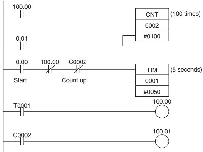
| Instruction | Operands |
| LD | 100.00 |
| LD | 0.01 |
| CNT | 2 |
| #0100 | |
| LD | 0.00 |
| AND NOT | 100.00 |
| AND NOT | C0002 |
| TIM | 1 |
| #0050 | |
| LD | T0001 |
| OUT | 100.00 |
| LD | C0002 |
| OUT | 100.01 |
3) Clock Pulse and CNT Instruction
In this example, a CNT instruction counts the pulses from the 1-s clock pulse to make a 700-second timer.
If the First Cycle Flag (A200.11) is ORed with the counter's reset input (CIO 0.01), the counter's PV will be reset to the SV (0700) when program execution begins rather than resuming the count from the previous PV.
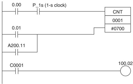
| Instruction | Operands |
| LD | 0.00 |
| AND | 1s |
| LD NOT | 0.01 |
| CNT | 1 |
| #0700 | |
| C0001 | |
| 100.02 |
Example 2: Two-stage Counter
When an SV higher than 9999 is required, two counters can be combined as shown in the following example. In this case, two CNT instructions are combined to make a BCD counter with an SV of 20,000.
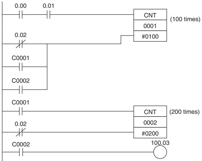
| Instruction | Operands |
| LD | 0.00 |
| AND | 0.01 |
| LD NOT | 0.02 |
| OR | C0001 |
| OR | C0002 |
| CNT | 1 |
| #0100 | |
| LD | C0001 |
| LD NOT | 0.02 |
| CNT | 2 |
| #0200 | |
| LD | C0002 |
| OUT | 100.03 |
Example 3: ON/OFF Delay
In this example two TIM timers are combined with KEEP(011) to make an ON delay and an OFF delay. CIO 5.00 will be turned ON 5.0 seconds after CIO 0.00 goes ON and it will be turned OFF 3.0 seconds after CIO 0.00 goes OFF.
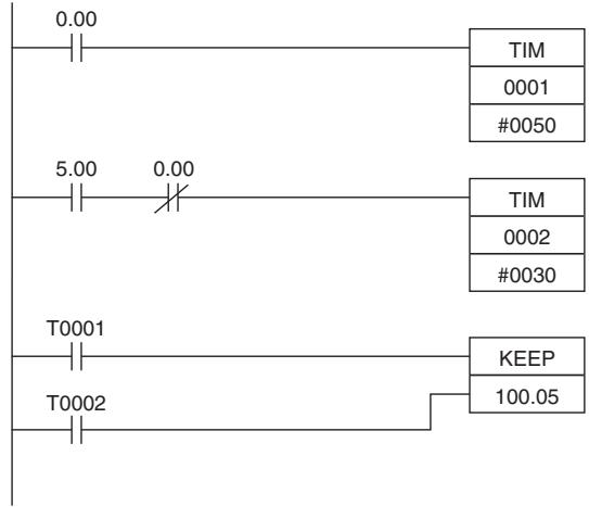
| Instruction | Operands |
| LD | 0.00 |
| TIM | 1 |
| #0050 | |
| LD | 5.00 |
| LD NOT | 0.00 |
| TIM | 2 |
| #0030 | |
| LD | T0001 |
| LD | T0002 |
| KEEP(011) | 100.05 |
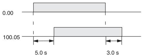
Example 4: One-shot Bit
A TIM timer can be combined with OUT or OUT NOT to control how long a particular bit is ON or OFF. In this example, CIO 2.04 will be ON for 1.5 seconds (the SV of T0001) after CIO 0.00 goes ON.
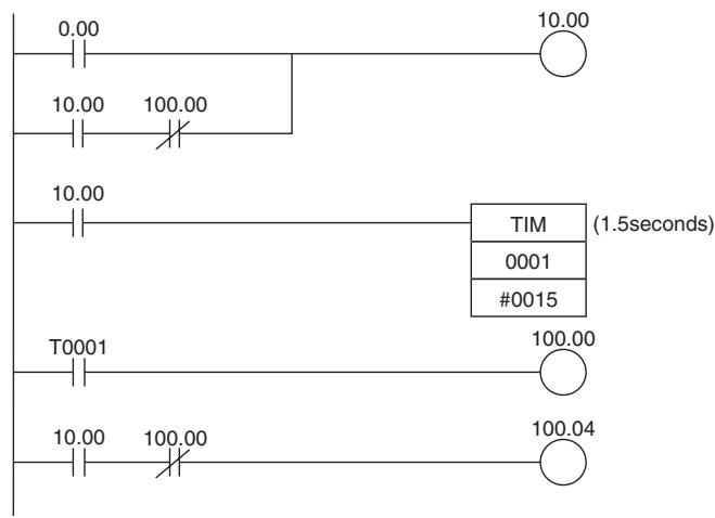
| Instruction | Operands |
| LD | 0.00 |
| LD | 10.00 |
| AND NOT | 100.00 |
| OR LD | -- |
| OUT | 10.00 |
| LD | 10.00 |
| TIM | 1 |
| #0015 | |
| LD | T0001 |
| OUT | 100.00 |
| LD | 10.00 |
| AND NOT | 100.00 |
| OUT | 100.04 |
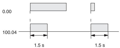
Example 5: Flicker Bit 1) Two TIM Instructions
Two TIM timers can be combined to make a bit turn ON and OFF at regular intervals while the execution condition is ON. In this example, CIO 2.05 will be OFF for 1.0 second and then ON for 1.5 seconds as long as CIO 0.00 is ON.
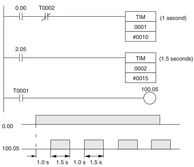
| Instruction | Operands |
| LD | 0.00 |
| AND LD | T0002 |
| TIM | 1 |
| #0010 | |
| LD | 2.05 |
| TIM | 2 |
| #0015 | |
| LD | T0001 |
| OUT | 100.05 |
2) Clock Pulse
The desired execution condition can be combined with a clock pulse to mimic the clock pulse (0.1 s, 0.2 s, or 1.0 s).
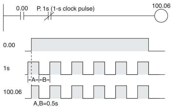
| Instruction | Operands |
| LD | 0.00 |
| AND | 1s |
| OUT | 100.06 |
- The internal clock pulse (0.1 s, 0.2 s, 1 s) can be used to easily program a flicker circuit.
- Timer reset method
There are two methods for resetting a timer instruction.
1. Turn OFF the execution condition for the timer instruction.
The timer will be reset when its execution condition turns OFF.
The timer will start timing again when its execution condition turns ON.
With this method, a timer cannot be reset and then restarted within the same cycle.
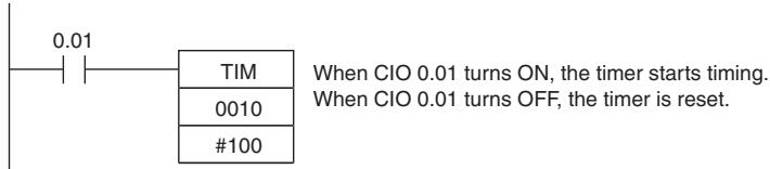
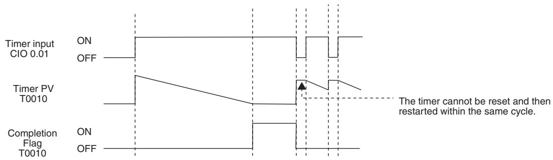
2. Use the RESET TIMER/COUNTER instruction.
The specified instruction will be reset when the RESET TIMER/COUNTER instruction (CNR/CNRX) is executed.
TIM/TIMX
| Instruction | Mnemonic | Variations | Function code | Function |
| HUNDRED-MS TIMER | TIM/TIMX | --- | 550 | TIM or TIMX(550) operates a decrementing timer with units of 0.1-s. |
| Symbol | TIM | TIMX | ||
| BCD | TIM | Binary | TIMX(550) | |
| N | N:Timer number | N:Timer number | ||
| S | S:Set value | S:Set value | ||
Applicable Program Areas
| Area | Step program areas | Subroutines | Interrupt tasks |
| Usage | OK | OK | Not allowed |
Operands
| Operand | Description | Data type | Size | |
| TIM | TIMX | |||
| N | Timer Number | TIMER | TIMER | 1 |
| S | Set Value | WORD | UINT | 1 |
N: Timer Number
The timer number must be between 0000 and 0255 (decimal).
S: Set Value (100-ms Units)
TIM (BCD): #0000 to #9999.
TIMX (Binary): &0 to &65535 (decimal) or #0000 to #FFFF (hex).
- Operand Specifications
| Area | Word addresses | Indirect DM addresses | Constants | CF | Pulse bits | TR bits | |||||||
| CIO | WR | HR | AR | T | C | DM | @DM | *DM | |||||
| N | --- | --- | --- | --- | OK | --- | --- | --- | --- | --- | --- | --- | --- |
| S | OK | OK | OK | OK | OK | OK | OK | OK | OK | ||||
Flags
| Name | Label | Operation |
| Error Flag | P_ER | ON if in BCD mode and S does not contain BCD dataOFF in all other cases. |
Function
- When the timer input is OFF, the timer specified by N is reset, i.e., the timer's PV is reset to the SV and its Completion Flag is turned OFF.
- When the timer input goes from OFF to ON, TIM/TIMX(550) starts decrementing the PV. The PV will continue timing down as long as the timer input remains ON and the timer's Completion Flag will be turned ON when the PV reaches 0.
- The status of the timer's PV and Completion Flag will be maintained after the timer times out. To restart the timer, the timer input must be turned OFF and then ON again or the timer's PV must be changed to a non-zero value (by MOV(021), for example).
- The setting range for the set value (SV) is 0 to 999.9 s for TIM and 0 to 6,553.5 s for TIMX(550).
- The timer accuracy is -0.01 to 0 s.
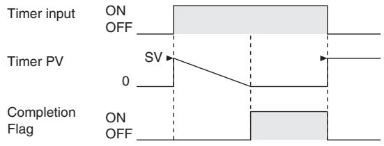
The following timing chart shows the behavior of the timer's PV and Completion Flag when the timer input is turned OFF before the timer times out.
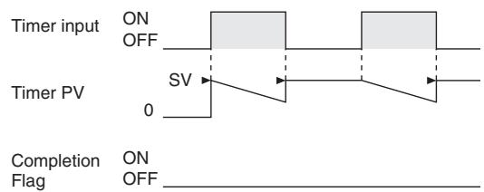
Hint
- A TIM/TIMX(550) instruction's PV and Completion Flag can be refreshed in the following ways depending on the timer number that is used.
| Refresh timing | Description |
| Execution of TIM/TIMX(550) | ·The PV is updated every time that TIM/TIMX(550) is executed. ·The Completion Flag is turned ON if the PV is 0. The Completion Flag is turned OFF if the PV is not 0. |
- Timers are reset (PV = SV, Completion Flag OFF) by power interruptions unless the IOM Hold Bit (A500.12) is ON and the bit is protected in the PLC Setup. It is also possible use a clock pulse bit and a counter instruction to program a timer that will retain its PV in the event of a power interruption, as shown in the following diagram.
- When the timer set value is #0000, timeup occurs when the instruction is executed.
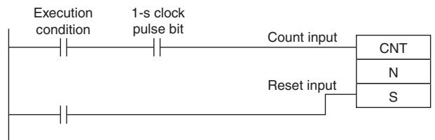
Precautions
- Timer numbers are shared with other timer instructions. If two timers share the same timer number, but are not used simultaneously, a duplication error will be generated when the program is checked, but the timers will operate normally. Timers which share the same timer number will not operate properly if they are used simultaneously.
- Timers will not operate properly when the CPU Unit cycle time exceeds 4s. Use timer instructions when the cycle time is no longer than 4s.
- Timers will be reset or paused in the following cases. (When a timer is reset, its PV is reset to the SV and its Completion Flag is turned OFF.)
| Condition | PV | Completion Flag |
| Operating mode changed from RUN or MONITOR mode to PROGRAM mode or vice versa.*1 | 0 | OFF |
| Power off and reset | 0 | OFF |
| Execution of CNR(545)/CNRX(547), the RESET TIMER/COUNTER instructions*2 | BCD: 9999 Binary: FFFF | OFF |
| Operation in interlocked program section (IL(002)–ILC(003)) | Reset to SV. | OFF |
| Operation in jumped program section (JMP(004)–JME(005)) | Retains previous status. | Retains previous status. |
1 If the IOM Hold Bit (A500.12) has been turned ON, the status of timer Completion Flags and PVs will be maintained when the operating mode is changed.
2 The PV will be set to the SV when TIM/TIMX(550) is executed.
- When TIM/TIMX(550) is in a program section between IL(002) and ILC(003) and the program section is interlocked, the PV will be reset to the SV and the Completion Flag will be turned OFF.
- When an operating TIM/TIMX(550) timer is in a jumped program section (JMP(004), CJP(510), JME(005)), the timer's PV will not be refreshed.
- When a TIM/TIMX(550) timer is forced set, its Completion Flag will be turned ON and its PV will be set to 0000. When a TIM/TIMX(550) timer is forced reset, its Completion Flag will be turned OFF and its PV will be reset to the SV.
- The timer's Completion Flag is refreshed only when TIM/TIMX(550) is executed, so a delay of up to one cycle may be required for the Completion Flag to be turned ON after the timer times out.
- If online editing is used to overwrite a timer instruction, always reset the Completion Flag. The timer will not operate properly unless the Completion Flag is reset.
Sample program
When timer input CIO 0.00 goes from OFF to ON in the following example, the timer PV will begin counting down from the SV. Timer Completion Flag T0000 will be turned ON when the PV reaches 0.
When CIO 0.00 goes OFF, the timer PV will be reset to the SV and the Completion Flag will be turned OFF.
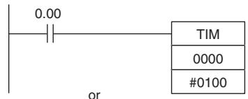
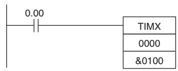
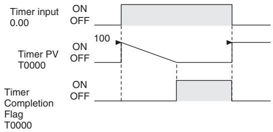
TIMH/TIMHX
| Instruction | Mnemonic | Variations | Function code | Function |
| TEN-MS TIMER | TIMH | --- | 015 | TIMH(015)/TIMHX(551) operates a decrementing timer with units of 10-ms. |
| TIMHX | --- | 551 |
| Symbol | TIMH | TIMHX | ||
| BCD | TIMH(015) | Binary | TIMHX(551) | |
| N | N | N: Timer number | ||
| S | S | S: Set value | ||
Applicable Program Areas
| Area | Step program areas | Subroutines | Interrupt tasks |
| Usage | OK | OK | Not allowed |
Operands
| Operand | Description | Data type | Size | |
| TIMH | TIMHX | |||
| N | Timer Number | TIMER | TIMER | 1 |
| S | Set Value | WORD | UINT | 1 |
N: Timer Number
The timer number must be between 0000 and 0255 (decimal).
S: Set Value
TIMH (BCD): #0000 to #9999
TIMHX (Binary): &0 to &65535 (decimal) or #0000 to FFFF (hex)
- Operand Specifications
| Area | Word addresses | Indirect DM addresses | Constants | CF | Pulse bits | TR bits | |||||||
| CIO | WR | HR | AR | T | C | DM | @DM | *DM | |||||
| N | --- | --- | --- | --- | OK | --- | --- | --- | --- | --- | --- | --- | --- |
| S | OK | OK | OK | OK | OK | OK | OK | OK | OK | ||||
Flags
| Name | Label | Operation |
| Error Flag | ER | ON if in BCD mode and S does not contain BCD dataOFF in all other cases. |
Function
- When the timer input is OFF, the timer specified by N is reset, i.e., the timer's PV is reset to the SV and its Completion Flag is turned OFF.
- When the timer input goes from OFF to ON, TIMH(015)/TIMHX(551) starts decrementing the PV. The PV will continue timing down as long as the timer input remains ON and the timer's Completion Flag will be turned ON when the PV reaches 0000.
- The status of the timer's PV and Completion Flag will be maintained after the timer times out. To restart the timer, the timer input must be turned OFF and then ON again or the timer's PV must be changed to a non-zero value (by MOV(021), for example).
- The setting range for the set value (SV) is 0 to 99.99 s for TIMH(015) and 0 to 655.35 s for TIMHX(551).
- The timer accuracy is 0 to 0.01 s.
Timer input
Timer PV
Completion Flag
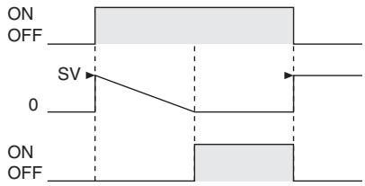
The following timing chart shows the behavior of the timer's PV and Completion Flag when the timer input is turned OFF before the timer times out.
Timer input
Timer PV
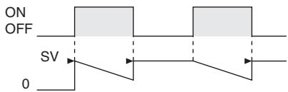
Completion
Flag
ON
OFF
Hint
A TIMH(015)/TIMHX(551) instruction's PV and Completion Flag can be refreshed in the following ways depending on the timer number that is used.
| Refresh timing | Description |
| Execution of TIMH(015)/TIMHX(551) | ·The PV is updated every time that TIMH(015)/TIMHX(551) is executed. ·The Completion Flag is turned ON if the PV is 0. The Completion Flag is turned OFF if the PV is not 0. |
Precautions
- Timer numbers are shared with other timer instructions. If two timers share the same timer number, but are not used simultaneously, a duplication error will be generated when the program is checked, but the timers will operate normally. Timers which share the same timer number will not operate properly if they are used simultaneously.
- Timers will not operate properly when the CPU Unit cycle time exceeds 4s. Use timer instructions when the cycle time is no longer than 4s.
- Timers will be reset or paused in the following cases. (When a timer is reset, its PV is reset to the SV and its Completion Flag is turned OFF.)
| Condition | PV | Completion Flag |
| Operating mode changed from RUN or MONITOR mode to PROGRAM mode or vice versa.*1 | 0 | OFF |
| Power off and reset | 0 | OFF |
| Execution of CNR(545)/CNRX(547), the RESET TIMER/COUNTER instructions*2 | BCD: 9999 Binary: FFFF | OFF |
| Operation in interlocked program section (IL(002)-ILC(003)) | Reset to SV. | OFF |
| Operation in jumped program section (JMP(004)-JME(005)) | Retains previous status. | Retains previous status. |
1 If the IOM Hold Bit (A500.12) has been turned ON, the status of timer Completion Flags and PVs will be maintained when the operating mode is changed.
2 The PV will be set to the SV when TIMH(015)/TIMHX(551) is executed.
- When an operating TIMH(015)/TIMHX(551) timer is in a jumped program section (JMP(004), CJP(510), JME(005)), the timer's PV will not be refreshed in the above case.
- When TIMH(015)/TIMHX(551) is in a program section between IL(002) and ILC(003) and the program section is interlocked, the PV will be reset to the SV and the Completion Flag will be turned OFF.
- When a TIMH(015)/TIMHX(551) timer is forced set, its Completion Flag will be turned ON and its PV will be set to 0000. When a TIMH(015)/TIMHX(551) timer is forced reset, its Completion Flag will be turned OFF and its PV will be reset to the SV.
- The timer's Completion Flag is refreshed only when TIMH(015)/TIMHX(551) is executed, so a delay of up to one cycle may be required for the Completion Flag to be turned ON after the timer times out.
- If online editing is used to overwrite a timer instruction, always reset the Completion Flag. The timer will not operate properly unless the Completion Flag is reset.
Sample program
When timer input CIO 0.00 goes from OFF to ON in the following example, the timer PV will begin counting down from the SV (#0064 = 100 = 1.00 s). The Timer Completion Flag, T0000, will be turned ON when the PV reaches 0.
When CIO 0.00 goes OFF, the timer PV will be reset to the SV and the Completion Flag will be turned OFF.
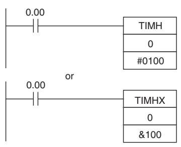
Timer input 0.00
Timer PV T0000 100 (1.00 s)
Timer Completion Flag T0000

TMHH/TMHHX
| Instruction | Mnemonic | Variations | Function code | Function |
| ONE-MS TIMER | TMHH | --- | 540 | TMHH(540)/TMHHX(552) operates a decrement-ing timer with units of 1-ms. |
| TMHHX | --- | 552 |
| Symbol | TMHH | TMHHX | ||
| BCD | TMHH(540) | Binary | TMHHX(552) | |
| N | N: Timer number | N: Timer number | ||
| S | S: Set value | S: Set value | ||
Applicable Program Areas
| Area | Step program areas | Subroutines | Interrupt tasks |
| Usage | OK | OK | Not allowed |
Operands
| Operand | Description | Data type | Size | |
| TMHH | TMHHX | |||
| N | Timer Number | TIMER | TIMER | 1 |
| S | Set Value | WORD | UINT | 1 |
N: Timer Number
The timer must be between 0000 and 0015 decimal.
S: Set Value
TMHH (BCD): #0000 to #9999
TMHHX (Binary): &0 to &65535 (decimal) or #0000 to #FFFF (hex)
-Operand Specifications
| Area | Word addresses | Indirect DM addresses | Constants | CF | Pulse bits | TR bits | |||||||
| CIO | WR | HR | AR | T | C | DM | @DM | *DM | |||||
| N | --- | --- | --- | --- | OK | --- | --- | --- | --- | --- | --- | --- | --- |
| S | OK | OK | OK | OK | OK | OK | OK | OK | OK | ||||
Flags
| Name | Label | Operation |
| Error Flag | P_ER | ON if in BCD mode and S does not contain BCD dataOFF in all other cases. |
Function
- When the timer input is OFF, the timer specified by N is reset, i.e., the timer's PV is reset to the SV and its Completion Flag is turned OFF.
- When the timer input goes from OFF to ON, TMHH(540)/TMHHX(552) starts decrementing the PV. The PV will continue timing down as long as the timer input remains ON and the timer's Completion Flag will be turned ON when the PV reaches 0000.
-
The status of the timer's PV and Completion Flag will be maintained after the timer times out. To restart the timer, the timer input must be turned OFF and then ON again or the timer's PV must be changed to a non-zero value (by MOV(021), for example).
-
The setting range for the set value (SV) is 0 to 9.999 s for TMHH(540) and 0 to 65.535 for TMHHX(552).
- The timer accuracy is -0.01 to 0 s.
Hint
The timer PV and timeup used in TMHH/TMHHX instructions are refreshed at the timing below.
| Refresh timing | Description |
| When each instruction is executed | ·The PV is updated every time that each instruction is executed. ·The timeup flag is ON when the PV is 0 and OFF otherwise. |
Precautions
- Timer numbers are shared with other timer instructions. If two timers share the same timer number, but are not used simultaneously, a duplication error will be generated when the program is checked, but the timers will operate normally. Timers which share the same timer number will not operate properly if they are used simultaneously.
- The Completion Flag is updated only when TMHH(540)/TMHHX(552) is executed. The Completion Flag can thus be delayed by up to one cycle time from the actual set value.
- The present value of a timer will not be refreshed even if the task is on standby.
- Timers will be reset or paused in the following cases. (When a timer is reset, its PV is reset to the SV and its Completion Flag is turned OFF.)
| Condition | PV | Completion Flag |
| Operating mode changed from RUN or MONITOR mode to PROGRAM mode or vice versa.*1 | 0 | OFF |
| Power supply interrupted and reset | 0 | OFF |
| Execution of CNR(545)/CNRX(547), the RESET TIMER/COUNTER instructions*2 | BCD: 9999 Binary: FFFF | OFF |
| Operation in interlocked program section (IL(002)-ILC(003)) | Reset to SV. | OFF |
| Operation in jumped program section (JMP(004)-JME(005)) | Retains previous status. | Retains previous status. |
1 If the IOM Hold Bit (A500.12) has been turned ON, the status of timer Completion Flags and PVs will be maintained when the operating mode is changed.
2 The PV will be set to the SV when TMHH(540)/TMHHX(552) is executed.
- The present value of all operating timers will not be refreshed even if the timer is in a program section that is jumped using JMP(004), CJP(510), JME(005).
- When TMHH(540)/TMHHX(552) is in a program section between IL(002) and ILC(003) and the program section is interlocked, the PV will be reset to the SV and the Completion Flag will be turned OFF.
- When a TMHH(540)/TMHHX(552) timer is forced set, its Completion Flag will be turned ON and its PV will be set to 0. When a TMHH(540)/TMHHX(552) timer is forced reset, its Completion Flag will be turned OFF and its PV will be reset to the SV.
- If online editing is used to overwrite a timer instruction, always reset the Completion Flag. The timer will not operate properly unless the Completion Flag is reset.
TTIM/TTIMX
| Instruction | Mnemonic | Variations | Function code | Function |
| ACCUMULATIVE TIMER | TTIM | --- | 087 | TTIM(087)/TTIMX(555) operates an incrementing timer with units of 0.1-s. |
| TTIMX | --- | 555 |
| Symbol | TTIM | TTIMX | ||||
| BCD | Timer input | TTIM(087) | Binary | Timer input | TTIMX(555) | |
| N | N: Timer number | Reset input | N: Timer number | |||
| Reset input | S | S: Set value | S | S: Set value | ||
Applicable Program Areas
| Area | Step program areas | Subroutines | Interrupt tasks |
| Usage | OK | OK | Not allowed |
Operands
| Operand | Description | Data type | Size | |
| TTIM | TTIMX | |||
| N | Timer Number | TIMER | TIMER | 1 |
| S | Set Value | WORD | UINT | 1 |
N: Timer Number
The timer number must be between 0000 to 0255 (decimal).
S: Set Value
TTIM (BCD): #0000 to #9999
TTIMX (Binary): &0 to &65535 (decimal) or #0000 to #FFFF (hex)
- Operand Specifications
| Area | Word addresses | Indirect DM addresses | Constants | CF | Pulse bits | TR bits | |||||||
| CIO | WR | HR | AR | T | C | DM | @DM | *DM | |||||
| N | --- | --- | --- | --- | OK | --- | --- | --- | --- | --- | --- | --- | --- |
| S | OK | OK | OK | OK | OK | OK | OK | OK | OK | ||||
Flags
| Name | Label | Operation |
| Error Flag | P_ER | ON if in BCD mode and S does not contain BCD dataOFF in all other cases. |
Function
- When the timer input is ON, TTIM(087)/TTIMX(555) increments the PV. When the timer input goes OFF, the timer will stop incrementing the PV, but the PV will retain its value. The PV will resume timing when the timer input goes ON again. The timer's Completion Flag will be turned ON when the PV reaches the SV.
- The status of the timer's PV and Completion Flag will be maintained after the timer times out. There are three ways to restart the timer: the timer's PV can be changed to a non-zero value (by MOV(021), for example), the reset input can be turned ON, or CNR(545)/CNRX(547) can be executed.
- The setting range for the set value (SV) is 0 to 999.9 s for TTIM(087) and 0 to 6,553.5 s for TTIMX(555).
- The timer accuracy is 0 to 0.01 s.
Timer input
Timer PV
Completion
Flag
Reset input
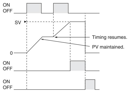
Hint
- Typical timers such as TIM/TIMX(550) are decrementing counters and the PV shows the time remaining until the timer times out. The PV of TTIM(087)/TTIMX(555) shows how much time has elapsed, so the PV can be used unchanged in many calculations and display outputs.
Precautions
- Timer numbers are shared with other timer instructions. If two timers share the same timer number, but are not used simultaneously, a duplication error will be generated when the program is checked, but the timers will operate normally. Timers which share the same timer number will not operate properly if they are used simultaneously.
- Timers will be reset or paused in the following cases. (When a TTIM(087)/TTIMX(555) timer is reset, its PV is reset to 0 and its Completion Flag is turned OFF.)
| Condition | PV | Completion Flag |
| Operating mode changed from RUN or MONITOR mode to PROGRAM mode or vice versa.*1 | 0 | OFF |
| Power supply interrupted and reset | 0 | OFF |
| Execution of CNR(545)/CNRX(547), the RESET TIMER/COUNTER instructions*2 | BCD: 9999 Binary: FFFF | OFF |
| Operation in interlocked program section (IL(002)-ILC(003)) | Retains previous status. | Retains previous status. |
| Operation in jumped program section (JMP(004)-JME(005)) | Retains previous status. | Retains previous status. |
1 If the IOM Hold Bit (A500.12) has been turned ON, the status of timer Completion Flags and PVs will be maintained when the operating mode is changed.
2 The PV will be set to the SV when TTIM(087)/TTIMX(555) is executed.
- When TTIM(087)/TTIMX(555) is in a program section between IL(002) and ILC(003) and the program section is interlocked, the PV will retain its previous value (it will not be reset). Be sure to take this fact into account when TTIM(087)/TTIMX(555) is programmed between IL(002) and ILC(003).
- When an operating TTIM(087)/TTIMX(555) timer is in a program section between JMP(004) and JME(005) and the program section is jumped, the PV will retain its previous value. Be sure to take this fact into account when TTIM(087)/TTIMX(555) is programmed between JMP(004) and JME(005).
- When a TTIM(087)/TTIMX(555) timer is forced set, its Completion Flag will be turned ON and its PV will be reset to 0. When a TTIM(087)/TTIMX(555) timer is forced reset, its Completion Flag will be turned OFF and its PV will be reset to 0. The forced set and forced reset operations take priority over the status of the timer and reset inputs.
- The timer's PV is refreshed only when TTIM(087)/TTIMX(555) is executed, so the timer will not operate properly when the cycle time exceeds 100 ms because the timer increments in 100-ms units.
- The timer's Completion Flag is refreshed only when TTIM(087)/TTIMX(555) is executed, so a delay of up to one cycle may be required for the Completion Flag to be turned ON after the timer times out.
Sample program
When timer input CIO 0.00 is ON in the following example, the timer PV will begin counting up from 0. Timer Completion Flag T0001 will be turned ON when the PV reaches the SV.
If the reset input is turned ON, the timer PV will be reset to 0 and the Completion Flag (T0001) will be turned OFF. (Usually the reset input is turned ON to reset the timer and then the timer input is turned ON to start timing.)
If the timer input is turned OFF before the SV is reached, the timer will stop timing but the PV will be maintained. The timer will resume from its previous PV when the timer input is turned ON again.
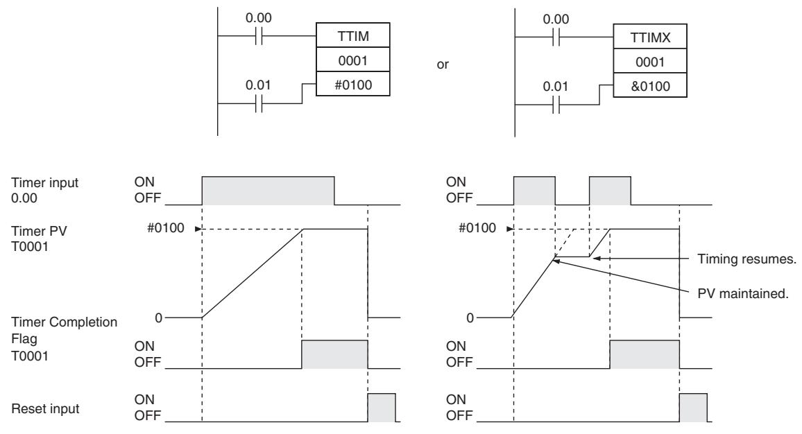
TIML/TIMLX
| Instruction | Mnemonic | Variations | Function code | Function |
| LONG TIMER | TIML | --- | 542 | TIML(542)/TIMLX(553) operates a decrementing timer with units of 0.1s. |
| TIMLX | --- | 553 |
| Symbol | TIML | TIMLX | ||
| BCD | TIML(542) | Binary | TIMLX(553) | |
| D1 | D1 | D1: Completion Flag | ||
| D2 | D2 | D2: PV word | ||
| S | S | S: SV word | ||
Applicable Program Areas
| Area | Step program areas | Subroutines | Interrupt tasks |
| Usage | OK | OK | Not allowed |
Operands
| Operand | Description | Data type | Size | |
| TIML | TIMLX | |||
| D1 | Completion Flag | WORD | UINT | 1 |
| D2 | PV word | DWORD | UDINT | 2 |
| S | SV word | DWORD | UDINT | 2 |
D1: Completion Flag
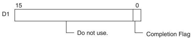
The PV and SV can range from #0000000 to #99999999 for TIML(542) and &0000000 to &4294967294 (decimal) or #0000000 to #FFFFFF (hexadecimal) for TIMLX(553).
Note S, S+1, D2 and D2+1 must be in the same data area.
D2: PV Word
D2
D2+1
D2

D2+1 is the leftmost 4 digits,
D2 is the rightmost 4 digits
S:SV Word
S
S+1

S

S + 1 is the leftmost 4 digits,
S is the rightmost 4 digits
- Operand Specifications
| Area | Word addresses | Indirect DM addresses | Constants | CF | Pulse bits | TR bits | |||||||
| CIO | WR | HR | AR | T | C | DM | @DM | *DM | |||||
| D1,D2 | OK | OK | OK | OK | --- | --- | OK | OK | OK | --- | --- | --- | --- |
| S | OK | OK | OK | ||||||||||
Flags
| Name | Label | Operation |
| Error Flag | P_ER | ON if in BCD mode and D2 does not contain BCD data.ON if in BCD mode and S does not contain BCD data.OFF in all other cases. |
Function
-
When the timer input is OFF, the timer is reset, i.e., the timer's PV is reset to the SV and its Completion Flag is turned OFF.
-
When the timer input goes from OFF to ON, TIML(542)/TIMLX(553) starts decrementing the PV in D2+1 and D2. The PV will continue timing down as long as the timer input remains ON and the timer's Completion Flag will be turned ON when the PV reaches 0.
-
The status of the timer's PV and Completion Flag will be maintained after the timer times out. To restart the timer, the timer input must be turned OFF and then ON again or the timer's PV must be changed to a non-zero value (by MOV(021), for example).
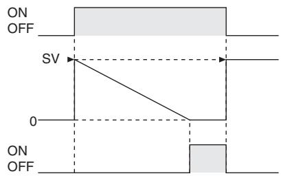
Timer input
Timer PV
Completion Flag (Bit 00 of D1)
- TIML(542)/TIMLX(553) can time up to 115 days for TIML(542) and 4,971 days for TIMLX(553).
- The timer accuracy is 0 to 0.01 s.
Precautions
- Unlike most timers, TIML(542)/TIMLX(553) does not use a timer number. (Timer area PV refreshing is not performed for TIML(542)/TIMLX(553).)
- Since the Completion Flag for TIML(542)/TIMLX(553) is in a data area it can be forced set or forced reset like other bits, but the PV will not change.
- The timer's PV is refreshed only when TIML(542)/TIMLX(553) is executed, so the timer will not operate properly when the cycle time exceeds 100 ms because the timer increments in 100-ms units.
- The timer's Completion Flag is refreshed only when TIML(542)/TIMLX(553) is executed, so a delay of up to one cycle may be required for the Completion Flag to be turned ON after the timer times out.
- When TIML(542)/TIMLX(553) is in a program section between IL(002) and ILC(003) and the program section is interlocked, the PV will be reset to the SV and the Completion Flag will be turned OFF.
- When an operating TIML(542)/TIMLX(553) timer is in a program section between JMP(004) and JME(005) and the program section is jumped, the PV will retain its previous value. Be sure to take this fact into account when TIML(542)/TIMLX(553) is programmed between JMP(004) and JME(005).
- Be sure that the words specified for the Completion Flag and PV (D1, D2, and D2+1) are not used in other instructions. If these words are affected by other instructions, the timer might not time out properly.
Sample program
When timer input CIO 0.00 is ON in the following example, the timer PV (in D201 and D200) will be set to the SV (in D101 and D100) and the PV will begin counting down. The timer Completion Flag (CIO 200.00) will be turned ON when the PV reaches 0.
When CIO 0.00 goes OFF, the timer PV will be reset to the SV and the Completion Flag will be turned OFF.
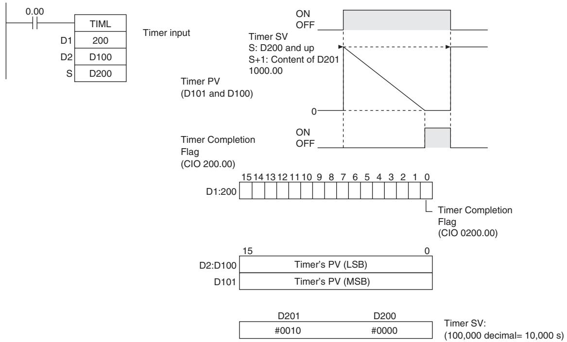
CNT/CNTX
| Instruction | Mnemonic | Variations | Function code | Function |
| COUNTER | CNT/CNTX | --- | 546 | CNT/CNTX(546) operates a decrementing counter. |
| Symbol | CNT | CNTX | ||||
| BCD Count input | Binary Count input | |||||
| Reset input | CNT | N: Counter number S: Set value | Reset input | CNTX(546) | N: Counter number S: Set value | |
| N | N | |||||
| S | S | |||||
Applicable Program Areas
| Area | Step program areas | Subroutines | Interrupt tasks |
| Usage | OK | OK | OK |
Operands
| Operand | Description | Data type | Size | |
| CNT | CNTX | |||
| N | Counter Number | COUNTER | COUNTER | 1 |
| S | Set Value | WORD | UINT | 1 |
N: Counter Number
The counter number must be between 0000 and 0255 (decimal).
S: Set Value
CNT (BCD): #0000 to #9999
CNTX (Binary): &0 to &65535 (decimal) or #0000 to #FFFF (hex)
-Operand Specifications
| Area | Word addresses | Indirect DM addresses | Constants | CF | Pulse bits | TR bits | |||||||
| CIO | WR | HR | AR | T | C | DM | @DM | *DM | |||||
| N | --- | --- | --- | --- | --- | OK | --- | --- | --- | --- | --- | --- | --- |
| S | OK | OK | OK | OK | OK | OK | OK | OK | OK | OK | OK | ||
Flags
| Name | Label | Operation |
| Error Flag | P_ER | ON if in BCD mode and S does not contain BCD dataOFF in all other cases. |
Function
- The counter PV is decremented by 1 every time that the count input goes from OFF to ON. The Completion Flag is turned ON when the PV reaches 0.
- Once the Completion Flag is turned ON, reset the counter by turning the reset input ON or by using the CNR(545)/CNRX(547) instruction. Otherwise, the counter cannot be restarted.
- The counter is reset and the count input is ignored when the reset input is ON. (When a counter is reset, its PV is reset to the SV and the Completion Flag is turned OFF.)
- The setting range 0 to 9,999 for CNT and 0 to 65,535 for CNTX(546).
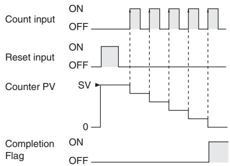
Hint
- Counter PVs are retained even through a power interruption. If you want to restart counting from the SV instead of resuming the count from the retained PV, add the First Cycle Flag (A200.11) as a reset input to the counter.
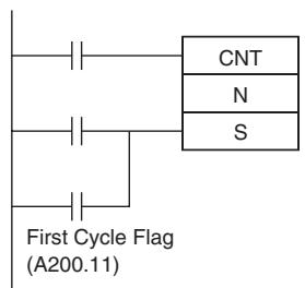
Note 1 In case CP1E CPU Unit is backed up in the capacitor and power remained OFF for a period in excess of the following, the Counters PVs and Countup Flags are unfixed.
E-type CPU Unit
9 hours (60^) , 50 hours (25^)
N/NA-type CPU Unit
7 hours (60^) 40 hours (25^)
2 By setting "Zero Clear Holding Memory" for the PLC Setup, the Counters PVs and Countup Flags will be cleared each time power turns ON. In this case, the DM area (D) and Holding Area (H) will be cleared at the same time.
3 N/NA-type CP1E CPU Unit (CP1E-N/NA□□D□-□) can be equipped with a battery. With the battery installed, the Counters PVs and Countup Flags can be retained during power OFF.
Precautions
- Counter numbers are shared by the CNT, CNTX(546), CNTR(012) and CNTRX(548) instructions. If two counters share the same counter number but are not used simultaneously, a duplication error will be generated when the program is checked but the counters will operate normally. Counters which share the same counter number will not operate properly if they are used simultaneously.
-
A counter's PV is refreshed when the count input goes from OFF to ON and the Completion Flag is refreshed each time that CNT/CNTX(546) is executed. The Completion Flag is turned ON if the PV is 0 and it is turned OFF if the PV is not 0.
-
When a CNT/CNTX(546) counter is forced set, its Completion Flag will be turned ON and its PV will be reset to 0000. When a CNT/CNTX(546) counter is forced reset, its Completion Flag will be turned OFF and its PV will be set to the SV.
- Be sure to reset the counter by turning the reset input from OFF ON OFF before beginning counting with the count input, as shown in the following diagram. The count input will not be received if the reset input is ON.
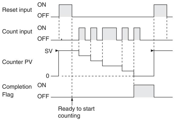
- The reset input will take precedence and the counter will be reset if the reset input and count input are both ON at the same time. (The PV will be reset to the SV and the Completion Flag will be turned OFF.)
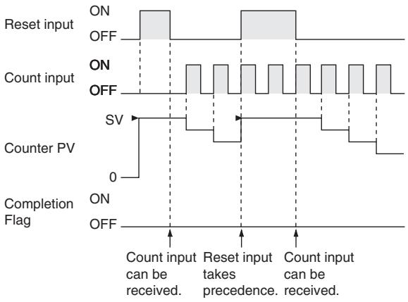
- If online editing is used to add a counter, the counter must be reset before it will work properly. If the counter is not reset, the previous value will be used as the counter's present value (PV), and the counter may not operate properly after it is written.
CNTR/CNTRX
| Instruction | Mnemonic | Variations | Function code | Function |
| REVERSIBLE COUNTER | CNTR | --- | 012 | --- |
| CNTRX | --- | 548 |
| Symbol | CNTR | CNTRX | ||||
| BCD | Increment input | CNTR(012) | Binary | Increment input | CNTRX(548) | |
| Decrement input | N | N: Counter number | Decrement input | N | N: Counter number | |
| Reset input | S | S: Set value | Reset input | S | S: Set value | |
Applicable Program Areas
| Area | Step program areas | Subroutines | Interrupt tasks |
| Usage | OK | OK | OK |
Operands
| Operand | Description | Data type | Size | |
| CNTR | CNTRX | |||
| N | Counter Number | COUNTER | COUNTER | 1 |
| S | Set Value | WORD | UINT | 1 |
N: Counter Number
The counter number must be between 0000 and 0255(decimal).
S: Set Value
CNTR (BCD):#0000 to #9999
CNTRX (Binary): &0 to &65535 (decimal) or #0000 to FFFF (hex)
- Operand Specifications
| Area | Word addresses | Indirect DM addresses | Constants | CF | Pulse bits | TR bits | |||||||
| CIO | WR | HR | AR | T | C | DM | @DM | *DM | |||||
| N | --- | --- | --- | --- | --- | OK | --- | --- | --- | --- | --- | --- | --- |
| S | OK | OK | OK | OK | OK | OK | OK | OK | OK | ||||
Flags
| Name | Label | Operation |
| Error Flag | P_ER | ON if in BCD mode and S does not contain BCD dataOFF in all other cases. |
Function
The counter PV is incremented by 1 every time that the increment input goes from OFF to ON and it is decremented by 1 every time that the decrement input goes from OFF to ON. The PV can fluctuate between 0 and the SV.
When incrementing, the Completion Flag will be turned ON when the PV is incremented from the SV back to 0 and it will be turned OFF again when the PV is incremented from 0 to 1.
When decrementing, the Completion Flag will be turned ON when the PV is decremented from 0 up to the SV and it will be turned OFF again when the PV is decremented from the SV to SV-1.
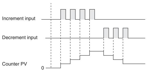
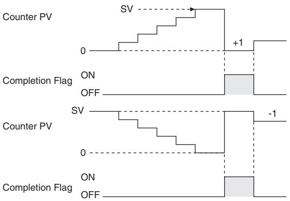
Precautions
- Counter numbers are shared by the CNT, CNTX(546), CNTR(012) and CNTRX(548) instructions. If two counters share the same counter number but are not used simultaneously, a duplication error will be generated when the program is checked but the counters will operate normally. Counters which share the same counter number will not operate properly if they are used simultaneously.
- The PV will not be changed if the increment and decrement inputs both go from OFF to ON at the same time. When the reset input is ON, the PV will be reset to 0 and both count inputs will be ignored.
- The Completion Flag will be ON only when the PV has been incremented from the SV to 0 or decremented from 0 to the SV; it will be OFF in all other cases.
- When inputting the CNTR(012)/CNTRX(548) instruction with mnemonics, first enter the increment input (II), then the decrement input (DI), the reset input (R), and finally the CNTR(012)/CNTRX(548) instruction. When entering with the ladder diagrams, first input the increment input (II), then the CNTR(012)/CNTRX(548) instruction, the decrement input (DI), and finally the reset input (R).
Sample program
The counter PV is reset to 0 by turning the reset input (CIO 0.02) ON and OFF. The PV is incremented by 1 each time that the increment input (CIO 0.00) goes from OFF to ON. When the PV is incremented from the SV (3), it is automatically reset to 0 and the Completion Flag is turned ON.
Likewise, the PV is decremented by 1 each time that the decrement input (CIO 0.01) goes from OFF to ON. When the PV is decremented from 0, it is automatically set to the SV (3) and the Completion Flag is turned ON.
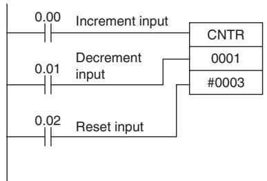
or
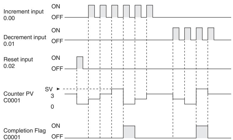
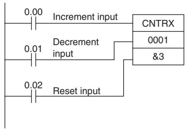
The add and subtract count inputs increase/decrease the count once when the signal rises (OFF to ON). When both inputs turn ON at the same time, neither increases/decreases the count. When the reset input turns ON, the PV changes to 0 and count input is not accepted.
In the following example, the SV for CNTR(012) 0007 is determined by the content of CIO 0001. When the content of CIO 0001 is controlled by an external switch, the set value can be changed manually from the switch.
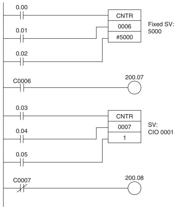
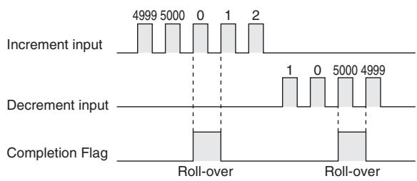
| Instruction | Operands |
| LD | 0.00 |
| LD | 0.01 |
| LD | 0.02 |
| CNTR (012) | 0006 |
| #5000 | |
| LD | 200.07 |
| OUT | 0.03 |
| LD | 0.04 |
| LD | 0.05 |
| LD | 0007 |
| CNTR (012) | 1 |
| LD NOT | C0007 |
| OUT | 200.08 |
CNR/CNRX
| Instruction | Mnemonic | Variations | Function code | Function |
| RESET TIMER/COUNTER | CNR | @CNR | 545 | Resetsthe timers or counters within the specified range of timer or counter numbers. |
| CNRX | @CNRX | 547 |
| Symbol | CNR | CNRX | ||
| BCD | CNR(545) | Binary | CNRX(547) | |
| N1 | N1: First number in range | N1: First number in range | ||
| N2 | N2: Last number in range | N2: Last number in range | ||
Applicable Program Areas
| Area | Step program areas | Subroutines | Interrupt tasks |
| Usage | OK | OK | OK |
Operands
| Operand | Description | Data type | Size | |
| CNT | CNTX | |||
| N1 | First number in range | TIMER/COUNTER*1 | Variable | |
| N2 | Last number in range | TIMER/COUNTER*1 | Variable | |
N1: First Number in Range
N1 must be a timer number between T000 and T255 or a counter number between C000 and C255.
N2: Last Number in Range
N2 must be a timer number between T000 and T255 or a counter number between C000 and C255.
-Operand Specifications
| Area | Word addresses | Indirect DM addresses | Constants | CF | Pulse bits | TR bits | |||||||
| CIO | WR | HR | AR | T | C | DM | @DM | *DM | |||||
| N1,N2 | --- | --- | --- | --- | OK | OK | --- | --- | --- | --- | --- | --- | --- |
Flags
| Name | Label | Operation |
| Error Flag | P_ER | ON if N1 and N2 are not in the same data areaOFF in all other cases. |
Function
CNR(545)/CNRX(547) resets the Completion Flags of all timers or counters from N1 to N2. At the same time, the PVs will all be set to the maximum value (9999 for BCD and FFFF for binary). (The PV will be set to the SV the next time that the timer or counter instruction is executed.)
Precautions
- The timer/counter that is reset is as follows.
| Instructions reset | Operation of CNR(545) | ||
| BCD | TIM: | HUNDRED-MS TIMER | The PV is set to its maximum value (9,999 BCD) and the Completion Flag is turned OFF. |
| TIMH(015): | TEN-MS TIMER | ||
| TMHH(540): | ONE-MS TIMER | ||
| TTIM(087): | ACCUMULATIVE TIMER | ||
| CNT: | COUNTER | ||
| CNTR(012): | REVERSIBLE COUNTER | ||
| Instructions reset | Operation of CNRX(547) | ||
| Binary | TIMX(550): | HUNDRED-MS TIMER | The PV is set to its maximum value (FFFF hex) and the Completion Flag is turned OFF. |
| TIMHX(551): | TEN-MS TIMER | ||
| TMHHX(552): | ONE-MS TIMER | ||
| TTIMX(555): | ACCUMULATIVE TIMER | ||
| CNTX(546): | COUNTER | ||
| CNTRX(548): | REVERSIBLE COUNTER | ||
- The CNR(545)/CNRX(547) instructions do not reset TIML(542) and TIMLX(553), because these timers do not use timer numbers.
- The CNR(545)/CNRX(547) instructions do not reset the timer/counter instructions themselves, they reset the PVs and Completion Flags allocated to those instructions. In most cases, the effect of CNR(545)/CNRX(547) is different from directly resetting the instructions. For example, when a TIM/TIMX(550) instruction is reset directly its PV is set to the SV, but when that timer is reset by CNR(545)/CNRX(547) its PV is set to the maximum value (9999 for BCD and FFFF for binary).
- When N1 and N2 are specified with N1>N2, only the Completion Flag for the timer/counter number will be reset.
Sample program
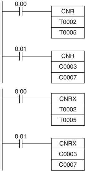
When CIO 0.00 is ON in the following example, the Completion Flags for timers T0002 to T0005 are turned OFF and the timers' PVs are set to the maximum value (9999 for BCD).
When CIO 0.01 is ON, the Completion Flags for counters C0003 to C0007 are turned OFF and the counters' PVs are set to the maximum value (9999 for BCD).
When CIO 0.00 is ON in the following example, the Completion Flags for timers T0002 to T0005 are turned OFF and the timers' PVs are set to the maximum value (FFFF for binary).
When CIO 0.01 is ON, the Completion Flags for counters C0003 to C0007 are turned OFF and the counters' PVs are set to the maximum value (FFFF for binary).
Comparison Instructions
$$ =, < >, < , < = , >, > = $$
| Instruction | Mnemonic | Variations | Function code | Function |
| Input Comparison Instructions | =, <>, <, <=, >, >= | --- | 300 to 328 | Input comparison instructions compare two values (constants and/or the contents of specified words) and create an ON execution condition when the comparison condition is true.Input comparison instructions are available to compare signed or unsigned data of one-word or double length data. |
| Symbol | =, <>, <, <=, >, >= | |||
| LD connection Mnemonic S1 S2 | S1: Comparison data 1 S2: Comparison data 2 | AND connection Mnemonic S1 S2 | OR connection Mnemonic S1 S2 | |
Applicable Program Areas
| Area | Step program areas | Subroutines | Interrupt tasks |
| Usage | OK | OK | OK |
Operands
| Operand | Description | Data type | Size | ||||
| Unsigned | Unsigned double length | Signed | Signed double length | One-word | Double length | ||
| S1 | Comparison data 1 | UINT | UDINT | INT | DINT | 1 | 2 |
| S2 | Comparison data 2 | UINT | UDINT | INT | DINT | 1 | 2 |
-Operand Specifications
| Area | Word addresses | Indirect DM addresses | Constants | CF | Pulse bits | TRbits | |||||||
| CIO | WR | HR | AR | T | C | DM | @DM | *DM | |||||
| S1,S2 | OK | OK | OK | OK | OK | OK | OK | OK | OK | OK | --- | --- | --- |
Flags
| Name | Label | Operation | |
| Data length: one-word | Data length: double length | ||
| Error Flag | P_ER | OFF or unchanged | OFF or unchanged |
| Greater Than Flag | P_GT | ON if S1 > S2 with one-word data. OFF in all other cases. | ON if S1+1, S1 > S2+1, S2 with double-length data. OFF in all other cases. |
| Greater Than or Equal Flag | P_GE | ON if S1 ≥ S2 with one-word data. OFF in all other cases. | ON if S1+1, S1 ≥ S2+1, S2 with double-length data. OFF in all other cases. |
| Equal Flag | P_EQ | ON if S1 = S2 with one-word data. OFF in all other cases. | ON if S1+1, S1 = S2+1, S2 with double-length data. OFF in all other cases. |
| Not Equal Flag | P_NE | ON if S1 ≠ S2 with one-word data. OFF in all other cases. | ON if S1+1, S1 ≠ S2+1, S2 with double-length data. OFF in all other cases. |
| Less Than Flag | P_LT | ON if S1 < S2 with one-word dataOFF in all other cases. | ON if S1+1, S1 < S2+1, S2 with double-length dataOFF in all other cases. |
| Less Than or Equal Flag | P_LE | ON if S1 ≤ S2 with one-word dataOFF in all other cases. | ON if S1+1, S1 ≤ S2+1, S2 with double-length dataOFF in all other cases. |
| Negative Flag | P_N | OFF or unchanged | OFF or unchanged |
Function
The input comparison instruction compares S1 and S2 as signed or unsigned values and creates an ON execution condition when the comparison condition is true.
The input comparison instructions are treated just like the LD, AND, and OR instructions to control the execution of subsequent instructions.
| Input type | Operation |
| LD | The instruction can be connected directly to the left bus bar. |
| AND | The instruction cannot be connected directly to the left bus bar. |
| OR | The instruction can be connected directly to the left bus bar. |
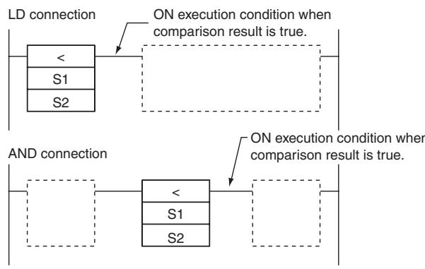
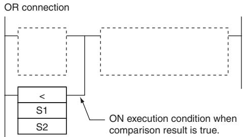
- Options
The input comparison instructions can compare signed or unsigned data and they can compare one-word or double values. If no options are specified, the comparison will be for one-word unsigned data. With the three input types and two options, there are 72 different input comparison instructions.
| Symbol | Option (data format) | Option (data length) |
| = (Equal) | None: Unsigned data | None: One-word data |
| < > (Not equal) | S: Signed data | L: Double-length data |
| < (Less than) | ||
| <= (Less than or equal) | ||
| > (Greater than) | ||
| >= (Greater than or equal) |
| Function | Mnemonic | Name | Code |
| True if C1 = C2 | LD/AND/OR = | EQUAL | 300 |
| LD/AND/OR =L | DOUBLE EQUAL | 301 | |
| LD/AND/OR =S | SIGNED EQUAL | 302 | |
| LD/AND/OR =SL | DOUBLE SIGNED EQUAL | 303 | |
| True if C1 ≠ C2 | LD/AND/OR <> | NOT EQUAL | 305 |
| LD/AND/OR <>L | DOUBLE NOT EQUAL | 306 | |
| LD/AND/OR <>S | SIGNED NOT EQUAL | 307 | |
| LD/AND/OR <>SL | DOUBLE SIGNED NOT EQUAL | 308 | |
| True if C1 < C2 | LD/AND/OR < | LESS THAN | 310 |
| LD/AND/OR <L | DOUBLE LESS THAN | 311 | |
| LD/AND/OR <S | SIGNED LESS THAN | 312 | |
| LD/AND/OR <SL | DOUBLE SIGNED LESS THAN | 313 | |
| True if C1 ≤ C2 | LD/AND/OR <= | LESS THAN OR EQUAL | 315 |
| LD/AND/OR<=L | DOUBLE LESS THAN OR EQUAL | 316 | |
| LD/AND/OR <=S | SIGNED LESS THAN OR EQUAL | 317 | |
| LD/AND/OR <=SL | DOUBLE SIGNED LESS THAN OR EQUAL | 318 | |
| True if C1 > C2 | LD/AND/OR > | GREATER THAN | 320 |
| LD/AND/OR >L | DOUBLE GREATER THAN | 321 | |
| LD/AND/OR >S | SIGNED GREATER THAN | 322 | |
| LD/AND/OR >SL | DOUBLE SIGNED GREATER THAN | 323 | |
| True if C1 ≥ C2 | LD/AND/OR >= | GREATER THAN OR EQUAL | 325 |
| LD/AND/OR >=L | DOUBLE GREATER THAN OR EQUAL | 326 | |
| LD/AND/OR >=S | SIGNED GREATER THAN OR EQUAL | 327 | |
| LD/AND/OR >=SL | DBL SIGNED GREATER THAN OR EQUAL | 328 |
Unsigned input comparison instructions (i.e., instructions without the S option) can handle unsigned binary or BCD data. Signed input comparison instructions (i.e., instructions with the S option) handle signed binary data.
Hint
- Unlike instructions such as CMP(020) and CMPL(060), the result of an input comparison instruction is reflected directly as an execution condition, so it is not necessary to access the result of the comparison through an Arithmetic Flag and the program is simpler and faster.
Precautions
- Input comparison instructions cannot be used as right-hand instructions, i.e., another instruction must be used between them and the right bus bar.
Sample program
AND LESS THAN: AND<(310)
When CIO 0.00 is ON in the following example, the contents of D100 and D200 are compared in as unsigned binary data. If the content of D100 is less than that of D200, CIO 100.00 is turned ON and execution proceeds to the next line. If the content of D100 is not less than that of D200, the remainder of the instruction line is skipped and execution moves to the next instruction line.
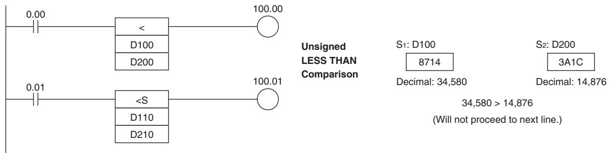
AND SIGNED LESS THAN: AND<312>
When CIO 0.01 is ON in the following example, the contents of D110 and D210 are compared as signed binary data. If the content of D110 is less than that of D210, CIO 100.01 is turned ON and execution proceeds to the next line. If the content of D110 is not less than that of D210, the remainder of the instruction line is skipped and execution moves to the next instruction line.
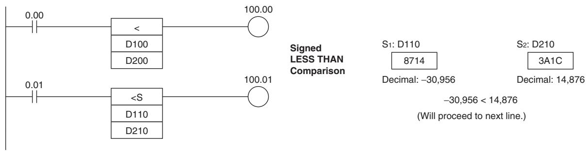
$$ = D T, < > D T, < D T, < = D T, > D T, > = D T $$
| Instruction | Mnemonic | Variations | Function code | Function |
| Time Comparison Instructions | =DT | --- | 341 | Time comparison instructions compare two BCD time values and create an ON execution condition when the comparison condition is true. |
| <>DT | 342 | |||
| <DT | 343 | |||
| <=DT | 344 | |||
| >DT | 345 | |||
| >=DT | 346 |
| Symbol | =DT, <>DT, <DT, <=DT, >DT, >=DT | |||
| LD | AND | OR | ||
| Symbol | Symbol | Symbol | C: Control word S1: First word of present time S2: First word of comparison time | |
| C | C | C | C: Control word S1: First word of present time S2: First word of comparison time | |
| S1 | S1 | S1 | S1 | |
| S2 | S2 | S2 | S2 | |
Applicable Program Areas
| Area | Step program areas | Subroutines | Interrupt tasks |
| Usage | OK | OK | OK |
Operands
| Operand | Description | Data type | Size |
| C | Control word | WORD | 1 |
| S1 | First word of present time | WORD | 3 |
| S2 | First word of comparison time | WORD | 3 |
C: Control Word
Bits 00 to 05 of C specify whether or not the time data will be masked for the comparison. Bits 00 to 05 mask the seconds, minutes, hours, day, month, and year, respectively. If all 6 values are masked, the instruction will not be executed, the execution condition will be OFF, and the Error Flag will be turned ON.
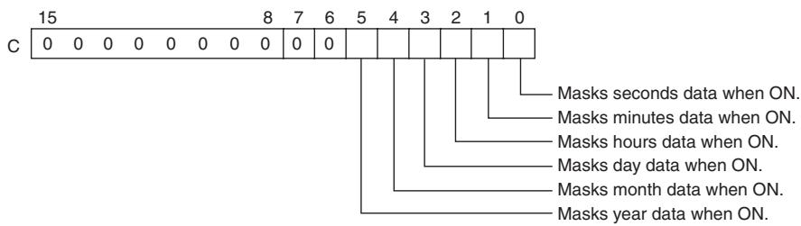
S_1 through S_1 + 2 : Present Time Data
S_1 through S_1 + 2 contain the present time data. S_1 through S_1 + 2 must be in the same data area.
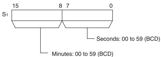
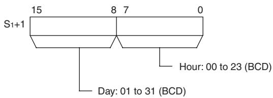
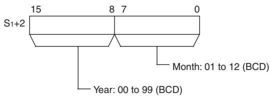
Note When using the CPU Unit's internal clock data for the comparison, set S1 to A351 to specify the CPU Unit's internal clock data (A351 to A353).
S_2 through S_2 + 2 : Comparison Time Data
S_2 through S_2 + 2 contain the comparison time data. S_2 through S_2 + 2 must be in the same data area.
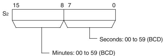
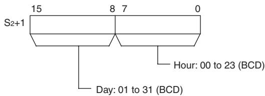
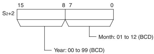
Note The year value indicates the last two digits of the year. Values 00 to 97 are interpreted as 2000 to 2097. Values 98 and 99 are interpreted as 1998 and 1999.
- Operand Specifications
| Area | Word addresses | Indirect DM addresses | Constants | CF | Pulse bits | TR bits | |||||||
| CIO | WR | HR | AR | T | C | DM | @DM | *DM | |||||
| C | OK | OK | OK | OK | OK | OK | OK | --- | --- | OK | --- | --- | --- |
| S1, S2 | OK | OK | --- | ||||||||||
Flags
| Name | Label | Operation |
| Error Flag | P_ER | ON if all 6 of the mask bits (C bits 00 to 05) are ON.OFF in all other cases. |
| Greater Than Flag | P_GT | ON if S1 > S2OFF in all other cases. |
| Greater Than or Equal Flag | P_GE | ON if S1 ≥ S2OFF in all other cases. |
| Equal Flag | P_EQ | ON if S1 = S2OFF in all other cases. |
| Not Equal Flag | P_NE | ON if S1 ≠ S2OFF in all other cases. |
| Less Than Flag | P_LT | ON if S1 < S2OFF in all other cases. |
| Less Than or Equal Flag | P_LE | ON if S1 ≤ S2OFF in all other cases. |
Function
The time comparison instruction compares the unmasked values (corresponding bit of C set to 0) of the present time data in S_1 to S_1 + 2 with the comparison time data in S_2 to S_2 + 2 and creates an ON execution condition when the comparison condition is true. At the same time, the result of a time comparison instruction is reflected in the arithmetic flags (=, <>, <, <=, >, >=) .
The time comparison instructions are treated just like the LD, AND, and OR instructions to control the execution of subsequent instructions.
There are 18 possible combinations of time comparison instructions.
Any time values that are masked in the control word (C) are not included in the comparison.
The following table shows the ON/OFF status of each flag for each comparison result.
| Result | Flag status | |||||
| = | <> | < | <= | > | >= | |
| S1 = S2 | ON | OFF | OFF | ON | OFF | ON |
| S1 > S2 | OFF | ON | OFF | OFF | ON | ON |
| S1 < S2 | OFF | ON | ON | ON | OFF | OFF |
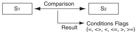
- Masking Time Values
Time values can be masked individually and excluded from the comparison operation. To mask a time value, set the corresponding bit in the control word (C) to 1. Bits 00 to 05 of C mask the seconds, minutes, hours, day, month, and year, respectively.
Example:
When C = 39 hex, the rightmost 6 bits are 111001 (year=1, month=1, day=1, hours=0, minutes=0, and seconds=1) so only the hours and minutes are compared. This mask setting can be used to perform a particular operation at a given time (hour and minute) each day.
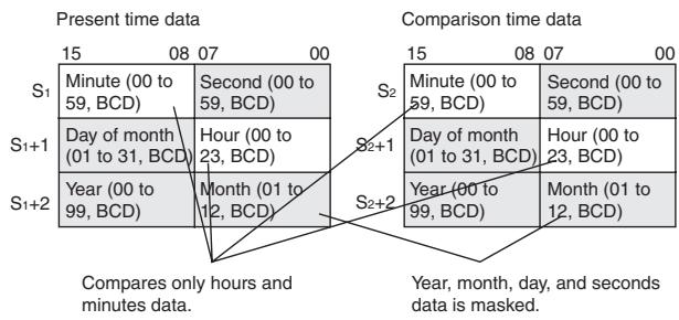
Hint
- Previous data comparison instructions compared data in 16-bit units. The time comparison instructions are limited to comparing 8-bit time values.
The following table shows the structure of the CPU Unit's internal Calendar/Clock Area.
| Addresses | Contents |
| A351.00 to A351.07 | Second (00 to 59, BCD) |
| A351.08 to A351.15 | Minute (00 to 59, BCD) |
| A352.00 to A352.07 | Hour (00 to 23, BCD) |
| A352.08 to A352.15 | Day of month (01 to 31, BCD) |
| A353.00 to A353.07 | Month (01 to 12, BCD) |
| A353.08 to A353.15 | Year (00 to 99, BCD) |
- The Calendar/Clock Area can be set with a Programming Device (including a Programming Console), DATE(735) instruction, or "CLOCK WRITE" FINS command (0702 hex).
Precautions
- Time comparison instructions cannot be used as right-hand instructions, i.e., another instruction must be used between them and the right bus bar.
- E-type CP1E CPU Unit (CP1E-E□□□□-□) does not have the clock function. The clock data inside the CPU Unit is always 01-01-01 01:01:01.
Sample program
When CIO 0.00 is ON and the time is 13:00:00, CIO 100.00 is turned ON. The contents of A351 to A353 (the CPU Unit's internal calendar/clock data) are used as the present time data and the contents of D100 to D102 are used as the comparison time data. The year, month, and day values are masked, so only the hour, minute, and second data are compared.
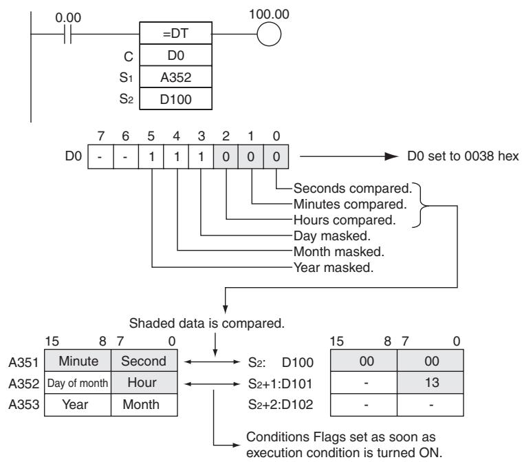
CMP/CMPL
| Instruction | Mnemonic | Variations | Function code | Function |
| COMPARE | CMP | !CMP | 020 | Compares two unsigned binary values (constants and/or the contents of specified words) and outputs the result to the Arithmetic Flags in the Auxiliary Area. |
| DOUBLE COMPARE | CMPL | --- | 060 | Compares two double unsigned binary values (constants and/or the contents of specified words) and outputs the result to the Arithmetic Flags in the Auxiliary Area. |
| Symbol | CMP | CMPL | ||
| CMP(020) | CMPL(060) | |||
| S1 | S1: Comparison data 1 | S1 | S1: Comparison data 1 | |
| S2 | S2: Comparison data 2 | S2 | S2: Comparison data 2 | |
Applicable Program Areas
| Area | Step program areas | Subroutines | Interrupt tasks |
| Usage | OK | OK | OK |
Operands
| Operand | Description | Data type | Size | ||
| CMP | CMPL | CMP | CMPL | ||
| S1 | CMP: Comparison data 1 CMPL: Comparison data 1, rightmost word address | UINT | UDINT | 1 | 2 |
| S2 | CMP: Comparison data 2 CMPL: Comparison data 2, rightmost word address | UINT | UDINT | 1 | 2 |
- Operand Specifications
| Area | Word addresses | Indirect DM addresses | Constants | CF | Pulse bits | TR bits | |||||||
| CIO | WR | HR | AR | T | C | DM | @DM | *DM | |||||
| S1, S2 | OK | OK | OK | OK | OK | OK | OK | OK | OK | OK | --- | --- | --- |
Flags
| Name | CX-Programmer label | Operation | |
| CMP | CMPL | ||
| Error Flag | P_ER | Unchanged | Unchanged |
| Greater Than Flag | P_GT | ON if S1 > S2.OFF in all other cases. | ON if S1 +1, S1 > S2+1, S2OFF in all other cases. |
| Greater Than or Equal Flag | P_GE | ON if S1 ≥ S2.OFF in all other cases. | ON if S1 +1, S1 ≥ S2+1, S2OFF in all other cases. |
| Equal Flag | P_EQ | ON if S1 = S2.OFF in all other cases. | ON if S1 +1, S1 = S2+1, S2OFF in all other cases. |
| Not Equal Flag | P_NE | ON if S1 ≠ S2.OFF in all other cases. | ON if S1 +1, S1 ≠ S2+1, S2OFF in all other cases. |
| Less Than Flag | P_LT | ON if S1 < S2.OFF in all other cases. | ON if S1 +1, S1 < S2+1, S2OFF in all other cases. |
| Less Than or Equal Flag | P_LE | ON if S1 ≤ S2.OFF in all other cases. | ON if S1 +1, S1 ≤ S2+1, S2OFF in all other cases. |
| Negative Flag | P_N | Unchanged | Unchanged |
- The following table shows the status of the Arithmetic Flags after execution of CMP(020).
| CMP(020) Result | Flag status | |||||
| > | >= | = | <= | < | <> | |
| S1 > S2 | ON | ON | OFF | OFF | OFF | ON |
| S1 = S2 | OFF | ON | ON | ON | OFF | OFF |
| S1 < S2 | OFF | OFF | OFF | ON | ON | ON |
- A status of “---” indicates that the Flag may be ON or OFF.
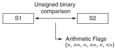
- The following table shows the status of the Arithmetic Flags after execution of CMPL(060).
| CMPL(060) Result | Flag status | |||||
| > | >= | = | <= | < | <> | |
| S1+1, S1>S2+1, S2 | ON | ON | OFF | OFF | OFF | ON |
| S1+1, S1=S2+1, S2 | OFF | ON | ON | ON | OFF | OFF |
| S1+1, S1<S2+1, S2 | OFF | OFF | OFF | ON | ON | ON |
- A status of “---” indicates that the Flag may be ON or OFF.
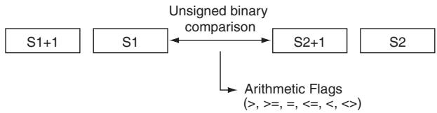
Function
- CMP
CMP(020) compares the unsigned binary data in S_1 and S_2 and outputs the result to Arithmetic Flags (the Greater Than, Greater Than or Equal, Equal, Less Than or Equal, Less Than, and Not Equal Flags) in the Auxiliary Area.
- CMPL
CMPL(060) compares the unsigned binary data in S_1 + 1 , S_1 and S_2 + 1 , S_2 and outputs the result to Arithmetic Flags (the Greater Than, Greater Than or Equal, Equal, Less Than or Equal, Less Than, and Not Equal Flags) in the Auxiliary Area.
Precautions
- Using CMP(020)Results in the Program
When CMP(020)/CMPL(060) is executed, the result is reflected in the Arithmetic Flags. Control the desired output or right-hand instruction with a branch from the same input condition that controls CMP(020)/CMPL(060), as shown in the following diagram. In this case, the Equals Flag and output A will be turned ON when S_1 = S_2 or S_1 + 1 , S_1 = S_2 + 1 , S_2 .
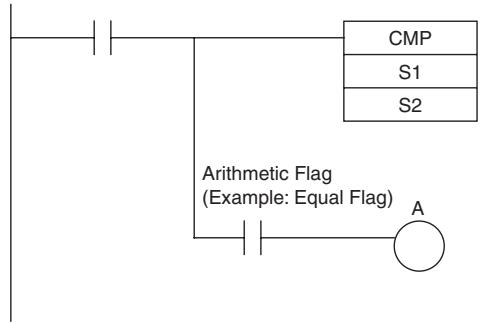
Using CMP(020) Results in the Program
Do not program another instruction between CMP(020)/CMPL(060) and the instruction controlled by the Arithmetic Flag because the other instruction might change the status of the Arithmetic Flag.
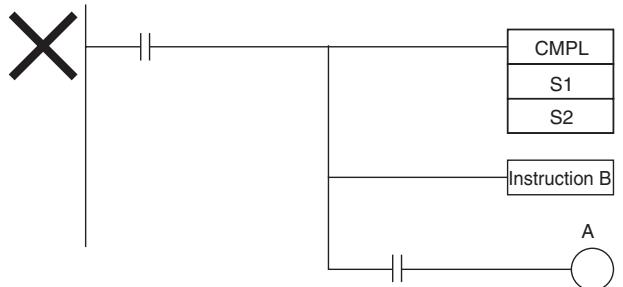
Arithmetic Flag
(Example: Equal Flag)
In this case, the results of instruction B might
change the results of CMP(020).
- The immediate-refreshing variation (!CMP(020)) can be used with words allocated to CPU Unit built-in inputs specified in S_1 and/or S_2 . When !CMP(020) is executed, input refreshing will be performed for the external input word specified in S_1 and/or S_2 and that refreshed value will be compared.
Sample program
- When CIO 0.00 is ON in the following example, the eight-digit unsigned binary data in CIO 0011 and CIO 0010 is compared to the eight-digit unsigned binary data in CIO 0009 and CIO 0008 and the result is output to the Arithmetic Flags. The results recorded in the Greater Than, Equals, and Less Than Flags are immediately saved to CIO 20.00 (Greater Than), CIO 20.01 (Equals), and CIO 20.02 (Less Than).
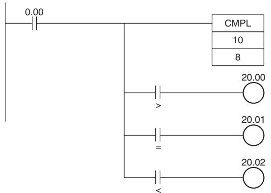
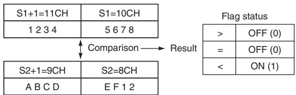
CPS/CPSL
| Instruction | Mnemonic | Variations | Function code | Function |
| SIGNED BINARY COMPRE | CPS | !CPS | 114 | Compares two signed binary values (constants and/or the contents of specified words) and outputs the result to the Arithmetic Flags in the Auxiliary Area. |
| DOUBLE SIGNED BINARY COMPRE | CPSL | --- | 115 | Compares two double signed binary values (constants and/or the contents of specified words) and outputs the result to the Arithmetic Flags in the Auxiliary Area. |
| Symbol | CPS | CPSL | ||
| — | — | — | — | |
| CPS(114) | S1: Comparison data 1 | CPSL(115) | ||
| S1 | S1 | S1: Comparison data 1 | ||
| S2 | S2 | S2: Comparison data 2 | ||
Applicable Program Areas
| Area | Step program areas | Subroutines | Interrupt tasks |
| Usage | OK | OK | OK |
Operands
| Operand | Description | Data type | Size | ||
| CPS | CPSL | CPS | CPSL | ||
| S1 | CMP: Comparison data 1 CMPL: Comparison data 1, rightmost word address | INT | DINT | 1 | 2 |
| S2 | CMP: Comparison data 2 CMPL: Comparison data 2, rightmost word address | INT | DINT | 1 | 2 |
- Operand Specifications
| Area | Word addresses | Indirect DM addresses | Constants | CF | Pulse bits | TR bits | |||||||
| CIO | WR | HR | AR | T | C | DM | @DM | *DM | |||||
| S1, S2 | OK | OK | OK | OK | OK | OK | OK | OK | OK | OK | --- | --- | --- |
Flags
| Name | Label | Operation | |
| CPS | CPSL | ||
| Error Flag | P_ER | Unchanged | OFF or unchanged |
| Greater Than Flag | P_GT | ON if S1 > S2. OFF in all other cases. | ON if S1 +1, S1 > S2+1, S2. OFF in all other cases. |
| Greater Than or Equal Flag | P_GE | ON if S1 ≥ S2. OFF in all other cases. | ON if S1 +1, S1 ≥ S2+1, S2. OFF in all other cases. |
| Equal Flag | P_EQ | ON if S1 = S2. OFF in all other cases. | ON if S1 +1, S1 = S2+1, S2. OFF in all other cases. |
| Not Equal Flag | P_NE | ON if S1 ≠ S2. OFF in all other cases. | ON if S1 +1, S1 ≠ S2+1, S2. OFF in all other cases. |
| Less Than Flag | P_LT | ON if S1 < S2. OFF in all other cases. | ON if S1 +1, S1 < S2+1, S2. OFF in all other cases. |
| Less Than or Equal Flag | P_LE | ON if S1 ≤ S2. OFF in all other cases. | ON if S1 +1, S1 ≤ S2+1, S2. OFF in all other cases. |
| Negative Flag | P_N | Unchanged | OFF or unchanged |
- The following table shows the status of the Arithmetic Flags after execution of CPS(114).
| Result | Flag status | |||||
| > | >= | = | <= | < | <> | |
| S1 > S2 | ON | ON | OFF | OFF | OFF | ON |
| S1 = S2 | OFF | ON | ON | ON | OFF | OFF |
| S1 < S2 | OFF | OFF | OFF | ON | ON | ON |
- A status of “---” indicates that the Flag may be ON or OFF.

- The following table shows the status of the Arithmetic Flags after execution of CPSL(115).
| Result | Flag status | |||||
| > | >= | = | <= | < | <> | |
| S1+1, S1>S2+1, S2 | ON | ON | OFF | OFF | OFF | ON |
| S1+1, S1=S2+1, S2 | OFF | ON | ON | ON | OFF | OFF |
| S1+1, S1<S2+1, S2 | OFF | OFF | OFF | ON | ON | ON |
- A status of “---” indicates that the Flag may be ON or OFF.
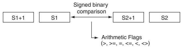
Function
- CPS
CPS(114) compares the signed binary data in S_1 and S_2 and outputs the result to Arithmetic Flags (the Greater Than, Greater Than or Equal, Equal, Less Than or Equal, Less Than, and Not Equal Flags) in the Auxiliary Area.
- CPSL
CPSL(115) compares the double signed binary data in S_1 + 1 , S_1 and S_2 + 1 , S_2 and outputs the result to Arithmetic Flags (the Greater Than, Greater Than or Equal, Equal, Less Than or Equal, Less Than, and Not Equal Flags) in the Auxiliary Area.
Precautions
- When CPS(114)/CPSL(115) is executed, the result is reflected in the Arithmetic Flags. Control the desired output or right-hand instruction with a branch from the same input condition that controls CPS(114)/CPSL(115), as shown in the following diagram.
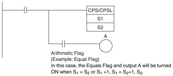
- Do not program another instruction between CPS(114)/CPSL(115) and the instruction controlled by the Arithmetic Flag because the other instruction might change the status of the Arithmetic Flag.
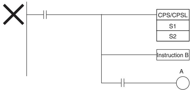
Arithmetic Flag
(Example: Equal Flag)
In this case, the results of instruction B might
change the results of CPS(114)/CPSL(115).
- The immediate-refreshing variation (!CPS(114)/!CPSL(115)) can be used with words allocated to CPU Unit built-in inputs specified in S_1 and/or S_2 . When !CPS(114)/!CPSL(115) is executed, input refreshing will be performed for the external input word specified in S_1 and/or S_2 and that refreshed value will be compared.
Sample program
When CIO 0.00 is ON in the following example, the eight-digit signed binary data in D2 and D1 is compared to the eight-digit signed binary data in D6 and D5 and the result is output to the Arithmetic Flags.
- If the content of D2 and D1 is greater than that of D6 and D5, the Greater Than Flag will be turned ON, causing CIO 20.00 to be turned ON.
- If the content of D2 and D1 is equal to that of D6 and D5, the Equals Flag will be turned ON, causing CIO 20.01 to be turned ON.
- If the content of D2 and D1 is less than that of D6 and D5, the Less Than Flag will be turned ON, causing CIO 20.02 to be turned ON.

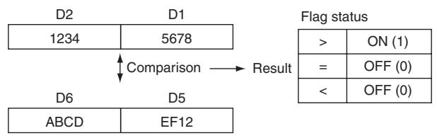
TCMP
| Instruction | Mnemonic | Variations | Function code | Function |
| TABLE COMPARE | TCMP | @TCMP | 085 | Compares the source data to the contents of 16 consecutive words and turns ON the corresponding bit in the result word when the contents of the words are equal. |
| Symbol | TCMP | |
| TCMP(085) | S: Source data T: First word of table R: Result word | |
| S | ||
| T | ||
| R | ||
Applicable Program Areas
| Area | Step program areas | Subroutines | Interrupt tasks |
| Usage | OK | OK | OK |
Operands
| Operand | Description | Data type | Size |
| S | Source data | WORD | 1 |
| T | First word of table | WORD | 16 |
| R | Result word | UINT | 1 |
T: First word of table
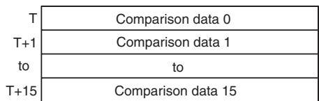
R: Result word
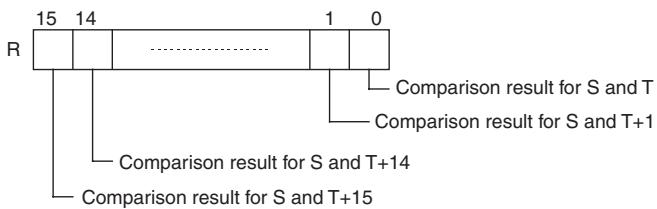
- Operand Specifications
| Area | Word addresses | Indirect DM addresses | Constants | CF | Pulse bits | TR bits | |||||||
| CIO | WR | HR | AR | T | C | DM | @DM | *DM | |||||
| S | OK | OK | OK | OK | OK | OK | OK | OK | OK | OK | --- | --- | --- |
| T, R | --- | ||||||||||||
Flags
| Name | Label | Operation |
| Error Flag | P_ER | OFF |
| Equals Flag | P_EQ | ON if the result word is 0000. (The two 16-word sets contain the same data.) OFF in all other cases. |
Function
TCMP(085) compares the source data (S) to each of the 16 words T through T + 15 and turns ON the corresponding bit in word R when the data are equal. Bit n of R is turned ON if the content of T + n is equal to S and it is turned OFF if they are not equal.
S is compared to the content of T and bit 00 of R is turned ON if they are equal or OFF if they are not equal, S is compared to the content of T + 1 and bit 01 of R is turned ON if they are equal or OFF if they are not equal, ..., and S is compared to the content of
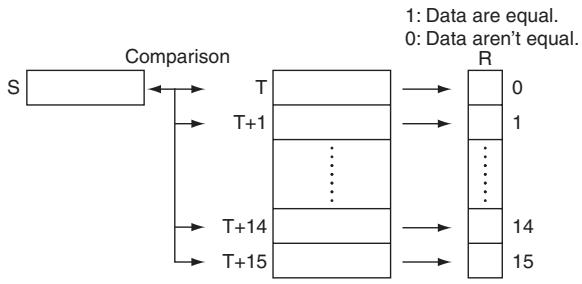
T + 15 and bit 15 of R is turned ON if they are equal or OFF if they are not equal.
Sample program
When CIO 0.00 is ON in the following example, TCMP(085) compares the content of D100 with the contents of words D200 through D215 and turns ON the corresponding bits in D300 when the contents are equal or OFF when the contents are not equal.
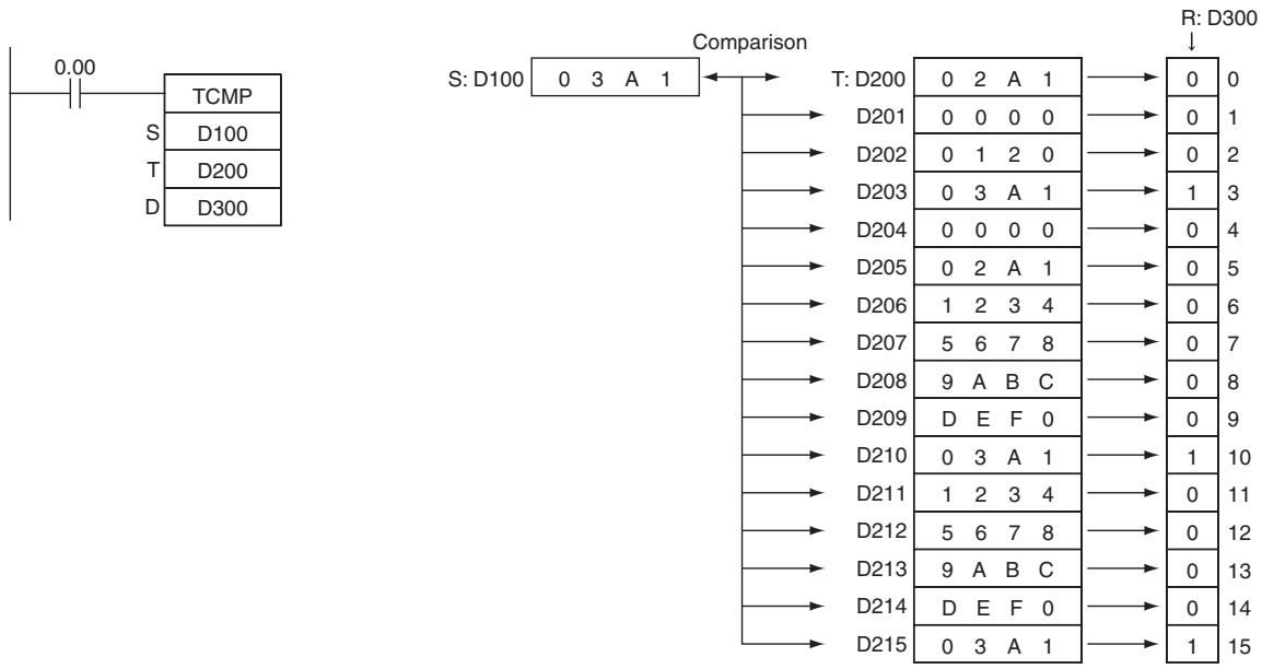
BCMP
| Instruction | Mnemonic | Variations | Function code | Function |
| BLOCK COMPARE | BCMP | @BCMP | 068 | Compares the source data to 16 ranges (defined by 16 lower limits and 16 upper limits) and turns ON the corresponding bit in the result word when the source data is within a range. |
| Symbol | BCMP |
| BCMP(068) | |
| S | |
| B | |
| R | |
| S: Source data B: First word of block R: Result word | |
Applicable Program Areas
| Area | Step program areas | Subroutines | Interrupt tasks |
| Usage | OK | OK | OK |
Operands
| Operand | Description | Data type | Size |
| S | Source data | WORD | 1 |
| B | First word of block | WORD | 32 |
| R | Result word | UINT | 1 |
B: First word of block
| B | Lower limit value 0 |
| B+1 | Upper limit value 0 |
| B+2 | Lower limit value 1 |
| B+3 | Upper limit value 1 |
| B+30 | Lower limit value 15 |
| B+31 | Upper limit value 15 |
R: Result word
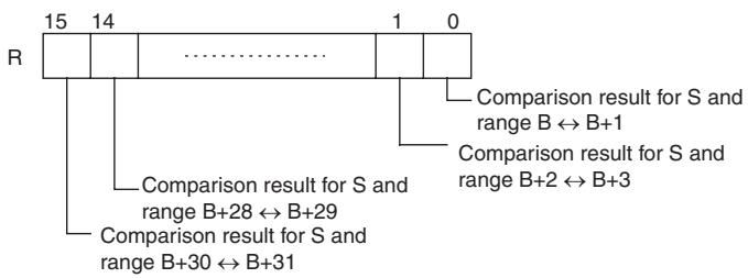
- Operand Specifications
| Area | Word addresses | Indirect DM addresses | Constants | CF | Pulse bits | TR bits | |||||||
| CIO | WR | HR | AR | T | C | DM | @DM | *DM | |||||
| S | OK | OK | OK | OK | OK | OK | OK | OK | OK | OK | --- | --- | --- |
| B | --- | ||||||||||||
| D | |||||||||||||
Flags
| Name | Label | Operation |
| Error Flag | P_ER | OFF |
| Equals Flag | P_EQ | ON if the result word is 0000. (S is not within any of the 16 ranges.) OFF in all other cases. |
Function
BCMP(068) compares the source data (S) to the 16 ranges defined by pairs of lower and upper limit values in B through B+31. The first word in each pair (B + 2n) provides the lower limit and the second word (B + 2n + 1) provides the upper limit of range n (n = 0 to 15). If S is within any of these ranges (inclusive of the upper and lower limits), the corresponding bit in R is turned ON. If S is out of any these ranges, the corresponding bit in R is turned OFF.
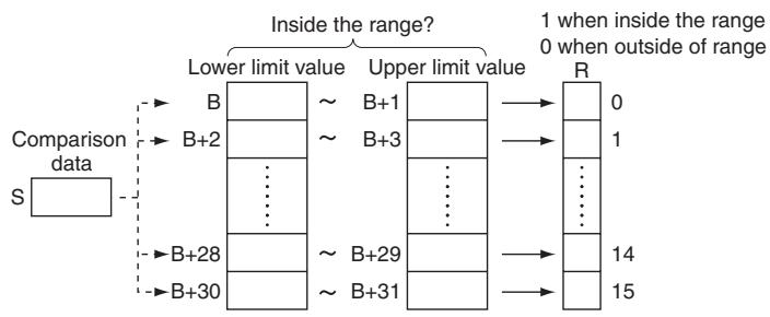
For example, bit 00 of R is turned ON if S is within the first range (B≤ S≤ B + 1) ,bit 01 of R is turned ON if S is within the second range (B + 2 ≤ S≤ B + 3) ,..., and bit 15 of R is turned ON if S is within the fifteenth range (B + 30≤ S≤ B + 31) All other bits in R are turned OFF.
Note An error will not occur if the lower limit is greater than the upper limit, but 0 (not within the range) will be output to the corresponding bit of R.
Sample program
When CIO 0.00 is ON in the following example, BCMP(068) compares the content of D100 with the 16 ranges defined in D200 through D231 and turns ON the corresponding bits in D300 when S is within the range or OFF when S is not within the range.
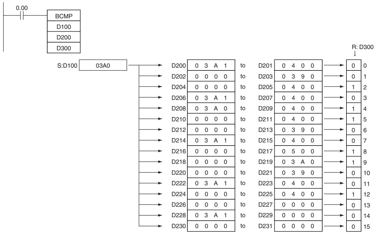
ZCP/ZCPL
| Instruction | Mnemonic | Variations | Function code | Function |
| AREA RANGE COMPRE | ZCP | --- | 088 | Compares a 16-bit unsigned binary value (CD) with the range defined by lower limit LL and upper limit UL. The results are output to the Arithmetic Flags. |
| DOUBLE AREA RANGE COMPRE | ZCPL | --- | 116 | Compares a 32-bit unsigned binary value (CD+1, CD) with the range defined by lower limit (LL+1, LL) and upper limit (UL+1, UL). The results are output to the Arithmetic Flags. |
| Symbol | ZCP | ZCPL | ||
| —|—|—|ZCP(088)—|—|—|CD|CD: Comparison DataLL: Lower limit of rangeUL: Upper limit of range | —|—|—|ZCP(116)—|—|—|CD|CD: First word of Comparison DataLL: First word of Lower LimitUL: First word of Upper Limit | |||
| CD | CD: Comparison Data | |||
| LL | LL | |||
| UL | UL | |||
Applicable Program Areas
| Area | Step program areas | Subroutines | Interrupt tasks |
| Usage | OK | OK | OK |
Operands
| Operand | Description | Data type | Size | ||
| CMP | CMPL | CMP | CMPL | ||
| CD | ZCP: Comparison data (one word of data) | UINT | UDINT | 1 | 2 |
| ZCPL: Comparison data (two words of data) | |||||
| LL | ZCP: Low limit | UINT | UDINT | 1 | 2 |
| ZCPL: Low limit leftmost word number | |||||
| UL | ZCP: High limit | UINT | UDINT | 1 | 2 |
| ZCPL: High limit rightmost word number | |||||
-Operand Specifications
| Area | Word addresses | Indirect DM addresses | Constants | CF | Pulse bits | TR bits | |||||||
| CIO | WR | HR | AR | T | C | DM | @DM | *DM | |||||
| CD, LL, UL | OK | OK | OK | OK | OK | OK | OK | OK | OK | OK | --- | --- | --- |
Flags
| Name | Label | Operation | |
| ZCP | ZCPL | ||
| Error Flag | P_ER | ON if LL > UL. | ON if LL+1, LL > UL+1, UL. |
| Greater Than Flag | P_GT | • ON if CD > UL. • OFF in all other cases. | • ON if CD > UL+1, UL. • OFF in all other cases. |
| Greater Than or Equal Flag | P_GE | Left unchanged. | Left unchanged. |
| Equal Flag | P_EQ | • ON if LL ≤ CD ≤ UL. • OFF in all other cases. | • ON if LL+1, LL ≤ CD+1, CD ≤ UL+1, UL. • OFF in all other cases. |
| Not Equal Flag | P_NE | Left unchanged. | Left unchanged. |
| Less Than Flag | P_LT | • ON if CD < LL. • OFF in all other cases. | • ON if CD+1, CD < LL+1, LL. • OFF in all other cases. |
| Less Than or Equal Flag | P_LE | Left unchanged. | Left unchanged. |
| Negative Flag | P_N | Left unchanged. | Left unchanged. |
Function
ZCP
ZCP(088) compares the 16-bit signed binary data in CD with the range defined by LL and UL and outputs the result to the Greater Than, Equals, and Less Than Flags in the Auxiliary Area. (The Less Than or Equal, Greater Than or Equal, and Not Equal Flags are left unchanged.)
When CD > UL as shown below, the > flag turns ON.
When LL ≤ CD ≤ UL , the = flag turns ON. When CD < LL , the < flag turns ON.
| ZCP(088)Result | Flag status | ||
| > | = | < | |
| CD > UL | ON | OFF | OFF |
| CD = UL | OFF | ON | |
| LL < CD < UL | |||
| CD = LL | |||
| CD < LL | OFF | ON | |
ZCPL
ZCPL(116) compares the 32-bit signed binary data in CD + 1 , CD with the range defined by LL + 1 , LL and UL+1, UL and outputs the result to the Greater Than, Equals, and Less Than Flags in the Auxiliary Area. (The Less Than or Equal, Greater Than or Equal, and Not Equal Flags are left unchanged.)
When CD + 1, CD > UL + 1, UL as shown below, the > flag turns ON.
When LL + 1, LL ≤ CD + 1, CD ≤ UL + 1, UL, the = flag turns ON.
When CD + 1 , CD < LL + 1 , LL , the < flag turns ON.
| ZCPL(116)Result | Flag status | ||
| > | = | < | |
| CD+1, CD > UL+1, UL | ON | OFF | OFF |
| CD+1, CD = UL+1, UL | OFF | ON | |
| LL+1, LL < CD+1, CD < UL+1, UL | |||
| CD+1, CD = LL+1, LL | |||
| CD+1, CD < LL+1, LL | OFF | ON | |
Precautions
- When ZCP(088)/ZCPL(116) is executed, the result is reflected in the Arithmetic Flags. Control the desired output or right-hand instruction with a branch from the same input condition that controls ZCP(088)/ZCPL(116), as shown in the following diagram.
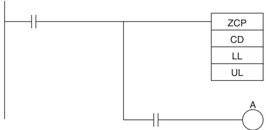
Arithmetic Flag
(Example: Equal Flag)
In this case, the Equals Flag and output A will be
turned ON when LL ≤ CD ≤ UL .
- Do not program another instruction between ZCP(088)/ZCPL(116) and the instruction controlled by the Arithmetic Flag because the other instruction might change the status of the Arithmetic Flag.
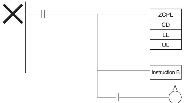
Arithmetic Flag
(Example: Equal Flag)
In this case, the results of instruction B
might change the results of ZCP(088)/ZCPL(116).
Sample program
- When CIO 0.00 is ON in the following example, the 16-bit unsigned binary data in D0 is compared to the range 0005 to 001F hex (5 to 31 decimal) and the result is output to the Arithmetic Flags.
CIO 20.00 is turned ON if 0005 hex ≤ content of D0≤ 001F hex.
CIO 20.01 is turned ON if the content of D0 > 001F hex.
CIO 20.02 is turned ON if the content of D0 < 0005 hex.
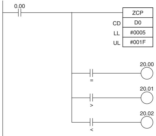
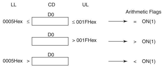
Data Movement Instructions
MOV/MOVL/MVN
| Instruction | Mnemonic | Variations | Function code | Function |
| MOVE | MOV | @MOV, !MOV, !@MOV | 021 | Transfers a word of data to the specified word. |
| DOUBLE MOVE | MOVL | @MOVL | 498 | Transfers two words of data to the specified words. |
| MOVE NOT | MVN | @MVN | 022 | Transfers the complement of a word of data to the specified word. |
| Symbol | MOV | MOVL | ||
| MOV(021)S D | S: SourceD: Destination | MOVL(498)S D | S: First source wordD: First destination word | |
| MVN | ||||
| MVN(022)S D | S: SourceD: Destination | |||
Applicable Program Areas
| Area | Step program areas | Subroutines | Interrupt tasks |
| Usage | OK | OK | OK |
Operands
| Operand | Description | Data type | Size | ||
| MOV / MVN | MOVL | MOV / MVN | MOVL | ||
| S | MOV / MVN: Source MOVL: First source word | WORD | DWORD | 1 | 2 |
| D | MOV / MVN: Destination MOVL: First destination word | WORD | DWORD | 1 | 2 |
- Operand Specifications
| Area | Word addresses | Indirect DM addresses | Constants | CF | Pulse bits | TR bits | |||||||
| CIO | WR | HR | AR | T | C | DM | @DM | *DM | |||||
| S | OK | OK | OK | OK | OK | OK | OK | OK | OK | OK | --- | --- | --- |
| D | --- | ||||||||||||
Flags
| Name | Label | Operation |
| Error Flag | P_ER | OFF |
| Equal Flag | P_EQ | ON if the data being transferred (D) is 0. OFF in all other cases. |
| Negative Flag | P_N | ON if the leftmost bit of the data being transferred (D) is 1. OFF in all other cases. |
Function
MOV
Transfers S to D. If S is a constant, the value can be used for a data setting.
- MOVL
MOVL(498) transfers S + 1 and S to D + 1 and D . If S + 1 and S are constants, the value can be used for a data setting.
MVN
MVN(022) inverts the bits in S and transfers the result to D. The content of S is left unchanged.
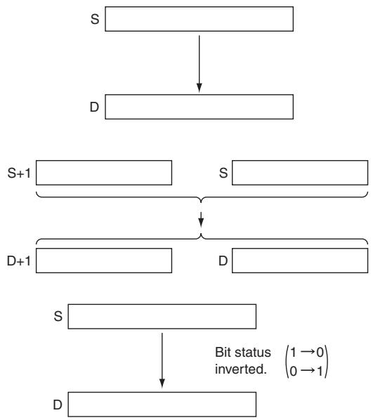
Precautions
MOV(021) has an immediate refreshing variation (!MOV(021)). A CPU Unit Built-in input bits can be specified for S and external output bits can be specified for D. Input bits used for S will refreshed just before, and output bits used for D will be refreshed just after execution.
When CPU Unit Built-in input is specified for S, the value of S will be in-refreshed when the instruction is executed and transferred to D. When external output is specified for D, the value of S will be transferred to D and immediately out-refreshed when the instruction is executed. It is also possible to refresh S and out-refresh D at the same time.
Sample program
When CIO 0.00 is ON in the following example, the content of CIO 100 is copied to D100.
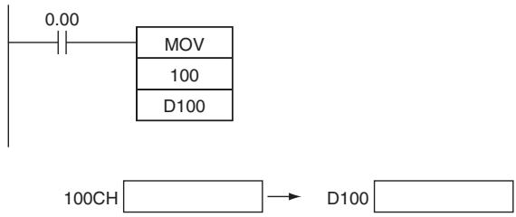
When CIO 0.00 is ON in the following example, the content of D101 and D100 are copied to D201 and D200.
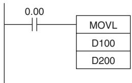
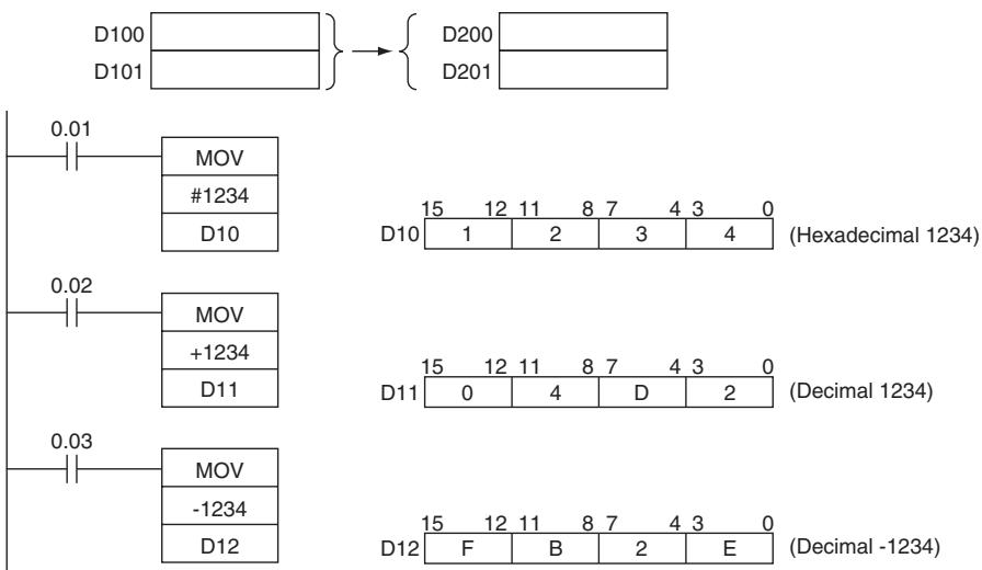
When CIO 0.00 is ON in the following example, the status of the bits in CIO 100 is inverted and the result is copied to D100.
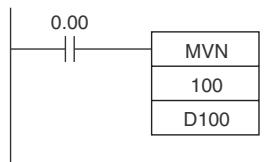
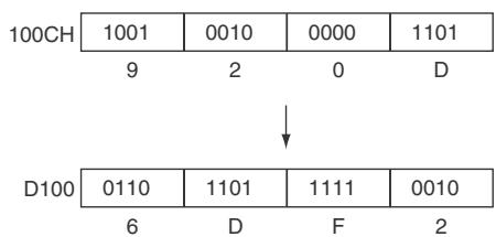
MOVB
| Instruction | Mnemonic | Variations | Function code | Function |
| MOVE BIT | MOVB | @MOVB | 082 | Transfers the specified bit. |
| Symbol | MOVB |
| MOVB(082) | |
| S | |
| C | |
| D |
Applicable Program Areas
| Area | Step program areas | Subroutines | Interrupt tasks |
| Usage | OK | OK | OK |
Operands
| Operand | Description | Data type | Size |
| S | Source word or data | WORD | 1 |
| C | Control word | UINT | 1 |
| D | Destination word | WORD | 1 |
C: Control Word
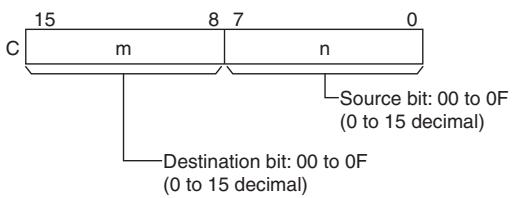
- Operand Specifications
| Area | Word addresses | Indirect DM addresses | Constants | CF | Pulse bits | TR bits | |||||||
| CIO | WR | HR | AR | T | C | DM | @DM | *DM | |||||
| S, C | OK | OK | OK | OK | OK | OK | OK | OK | OK | OK | --- | --- | --- |
| D | --- | ||||||||||||
Flags
| Name | Label | Operation |
| Error Flag | P_ER | ON if the rightmost and leftmost two digits of C are not within the specified range of 00 to 0FOFF in all other cases. |
Function
MOVB(082) copies the specified bit (n) from S to the specified bit (m) in D.
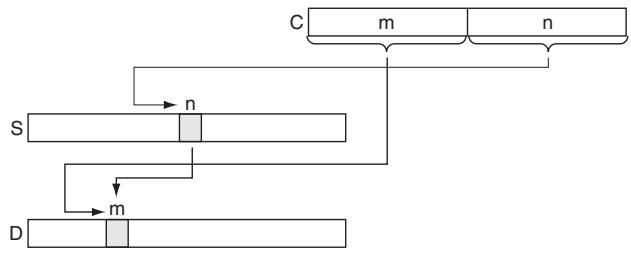
Hint
The same word can be specified for both S and D to copy a bit within a word.
Precautions
The other bits in the destination word are left unchanged.
Sample program
When CIO 0.00 is ON in the following example, the 5^th bit of the source word (W0) is copied to the 12^th bit of the destination word (W100) in accordance with the control word's value of 0C05.
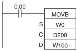
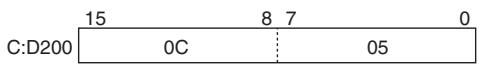
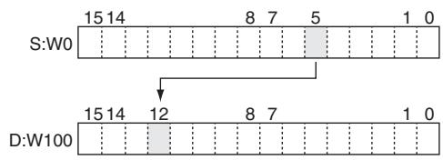
MOVD
| Instruction | Mnemonic | Variations | Function code | Function |
| MOVE DIGIT | MOVD | @MOVD | 083 | Transfers the specified digit or digits. (Each digit is made up of 4 bits.) |
| Symbol | MOVB |
| MOVD(083) | |
| S | |
| C | |
| D |
Applicable Program Areas
| Area | Step program areas | Subroutines | Interrupt tasks |
| Usage | OK | OK | OK |
Operands
| Operand | Description | Data type | Size |
| S | Source word or data | WORD | 1 |
| C | Control word | UINT | 1 |
| D | Destination word | UINT | 1 |
S: Source Word
| S | 15 | 12 | 11 | 8 | 7 | 4 | 3 | 0 |
| Digit 3 | Digit 2 | Digit 1 | Digit 0 |
The source digits are read from right to left, wrapping back to the rightmost digit (digit 0) if necessary.
D: Destination Word
| 15 | 12 | 11 | 8 | 7 | 4 | 3 | 0 |
| Digit 3 | Digit 2 | Digit 1 | Digit 0 | ||||
The destination digits are written from right to left, wrapping back to the rightmost digit (digit 0) if necessary.
C: Control Word
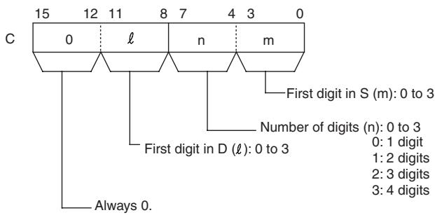
- Operand Specifications
| Area | Word addresses | Indirect DM addresses | Constants | CF | Pulse bits | TR bits | |||||||
| CIO | WR | HR | AR | T | C | DM | @DM | *DM | |||||
| S, C | OK | OK | OK | OK | OK | OK | OK | OK | OK | OK | --- | --- | --- |
| D | --- | ||||||||||||
Flags
| Name | Label | Operation |
| Error Flag | P_ER | ON if one of the first three digits of C is not within the specified range of 0 to 3. OFF in all other cases. |
Function
MOVB(082) copies the specified bit (n) from S to the specified bit (m) in D. The other bits in the destination word are left unchanged.
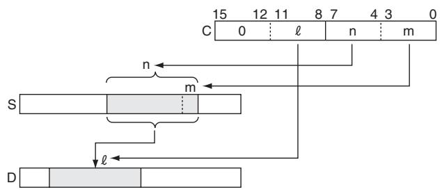
Precautions
If the number of digits being read or written exceeds the leftmost digit of S or D, MOVD(083) will wrap to the rightmost digit of the same word.
Sample program
When CIO 0.00 is ON in the following example, four digits of data are copied from W0 to W100. The transfer begins with the digit 1 of W0 and digit 0 of W100, in accordance with the control word's value of 31.
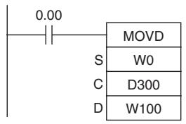
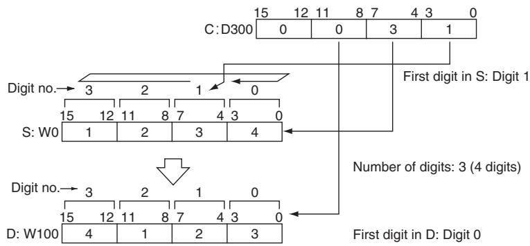
Note After reading the leftmost digit of S (digit 3), MOVD(083) wraps to the rightmost digit (digit 0).
- Example of transferring multiple digits
The following diagram shows examples of data transfers for various values of C.
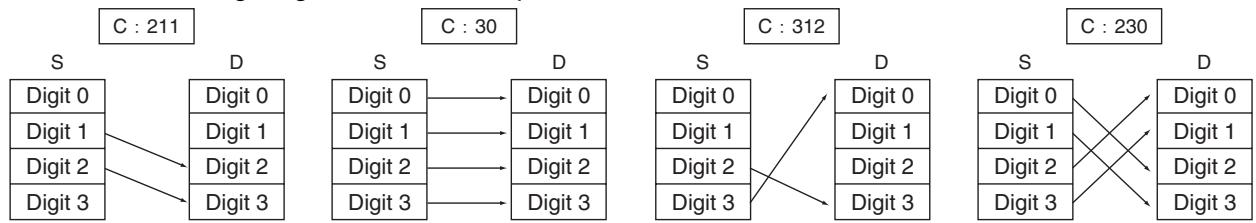
XFRB
| Instruction | Mnemonic | Variations | Function code | Function |
| MULTIPLE BIT TRANSFER | XFRB | @XFRB | 062 | Transfers the specified number of consecutive bits. |
| Symbol | XFRB |
| XFRB(062) | |
| C | |
| S | |
| D |
Applicable Program Areas
| Area | Step program areas | Subroutines | Interrupt tasks |
| Usage | OK | OK | OK |
Operands
| Operand | Description | Data type | Size |
| C | Control word | UINT | 1 |
| S | First source word | WORD | Variable |
| D | First destination word | WORD | Variable |
C: Control Word
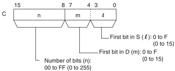
D: First destination Word
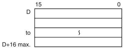
Note The source words and the destination words must be in the same data area respectively.
S: First Source Word
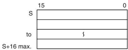
- Operand Specifications
| Area | Word addresses | Indirect DM addresses | Constants | CF | Pulse bits | TR bits | |||||||
| CIO | WR | HR | AR | T | C | DM | @DM | *DM | |||||
| C | OK | OK | OK | OK | OK | OK | OK | OK | OK | OK | --- | --- | --- |
| S, D | --- | ||||||||||||
Flags
| Name | Label | Operation |
| Error Flag | P_ER | OFF |
Function
XFRB(062) transfers up to 255 consecutive bits from the source words (beginning with bit I of S) to the destination words (beginning with bit m of D).
The beginning bits and number of bits are specified in C, as shown in the following diagram.
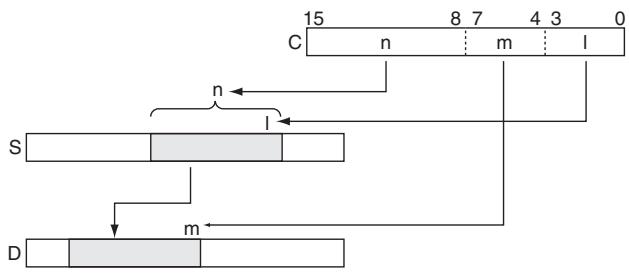
Hint
- Up to 255 bits of data can be transferred per execution of XFRB(062).
- It is possible for the source words and destination words to overlap. By transferring data overlapping several words, the data can be packed more efficiently in the data area. (This is particularly useful when handling position data for position control.)
- Since the source words and destination words can overlap, XFRB(062) can be combined with ANDW(034) to shift m bits by n spaces.
Precautions
- Be sure that the source words and destination words do not exceed the end of the data area.
- When the number of transfer bits (n of C) is 0, transfer does not take place.
- Bits in the destination words that are not overwritten by the source bits are left unchanged.
Sample program
When CIO 0.00 is ON in the following example, the 20 bits beginning with W0.06 are copied to the 20 bits beginning with W100.
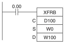
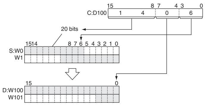
XFER
| Instruction | Mnemonic | Variations | Function code | Function |
| BLOCK TRANSFER | XFER | @XFER | 070 | Transfers the specified number of consecutive words. |
| Symbol | XFER | ||
| — | — | XFER(070) — | ||
| N | N: Number of words | ||
| S | S: First source word | ||
| D | D: First destination word | ||
Applicable Program Areas
| Area | Step program areas | Subroutines | Interrupt tasks |
| Usage | OK | OK | OK |
Operands
| Operand | Description | Data type | Size |
| N | Number of words | UINT | 1 |
| S | First source word | WORD | Variable |
| D | First destination word | WORD | Variable |
N: Number of Words
Specifies the number of words to be transferred. The possible range for N is 0000 to FFFF (0 to 65,535 decimal).
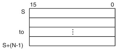
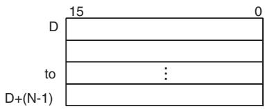
- Operand Specifications
| Area | Word addresses | Indirect DM addresses | Constants | CF | Pulse bits | TR bits | |||||||
| CIO | WR | HR | AR | T | C | DM | @DM | *DM | |||||
| N | OK | OK | OK | OK | OK | OK | OK | OK | OK | OK | --- | --- | --- |
| S, D | --- | ||||||||||||
Flags
| Name | Label | Operation |
| Error Flag | P_ER | OFF |
Function
XFER(070) copies N words beginning with S (S to S + (N - 1) ) to the N words beginning with D (D to D + (N - 1) ).
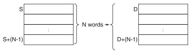
Hint
- It is possible for the source words and destination words to overlap, so XFER(070) can perform word-shift operations.
- The specified source and destination data areas can overlap (word shift).
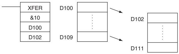
Precautions
- Be sure that the source words (S to S+N-1) and destination words (D to D+N-1) do not exceed the end of the data area.
- Some time will be required to complete XFER(070) when a large number of words is being transferred. Even if an interrupt occurs, execution of this instruction will not be interrupted and execution of the interrupt task will be started after execution of XFER(070) has been completed. If power is interrupted during execution of XFER(070), execution may not be completed, i.e., all of the specified data may not be transferred.
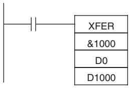
Sample Program
When CIO 0.00 is ON in the following example, the 10 words D100 through D109 are copied to D200 through D209.

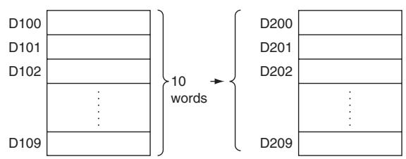
BSET
| Instruction | Mnemonic | Variations | Function code | Function |
| BLOCK SET | BSET | @BSET | 071 | Copies the same word to a range of consecutive words. |
| Symbol | BSET |
| — | — BSET(071) — S: Source wordSt: Starting wordE: End word |
Applicable Program Areas
| Area | Step program areas | Subroutines | Interrupt tasks |
| Usage | OK | OK | OK |
Operands
| Operand | Description | Data type | Size |
| S | Source word | WORD | 1 |
| St | Starting word | WORD | Variable |
| E | End word | WORD | Variable |
St: Starting Word
Specifies the first word in the destination range.
E: End Word
Specifies the last word in the destination range.
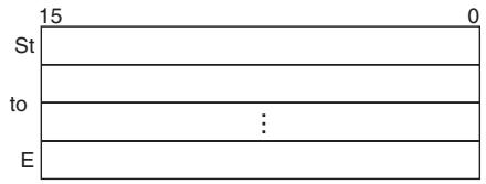
Note St and E must be in the same data area.
-Operand Specifications
| Area | Word addresses | Indirect DM addresses | Constants | CF | Pulse bits | TR bits | |||||||
| CIO | WR | HR | AR | T | C | DM | @DM | *DM | |||||
| S | OK | OK | OK | OK | OK | OK | OK | OK | OK | OK | --- | --- | --- |
| St, E | --- | ||||||||||||
Flags
| Name | Label | Operation |
| Error Flag | P_ER | ON if St is greater than EOFF in all other cases. |
Function
BSET(071) copies the same source word (S) to all of the destination words in the range St to E.
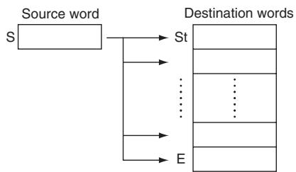
Precautions
- Some time will be required to complete BSET(071) when a large number of words is being set. Even if an interrupt occurs, execution of this instruction will not be interrupted and execution of the interrupt task will be started after execution of BSET(071) has been completed. If power is interrupted during execution of BSET(071), execution may not be completed, i.e., all of the specified words may not be set. One BSET(071) instruction can be replaced with two BSET(071) instructions to help avoid this problem.
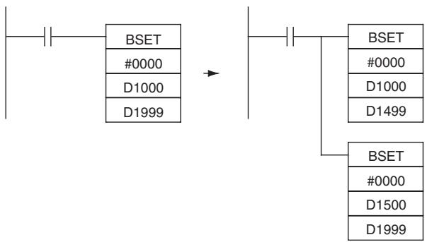
Sample program
When CIO 0.00 is ON in the following example, the source data in D100 is copied to D200 through D209.
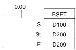
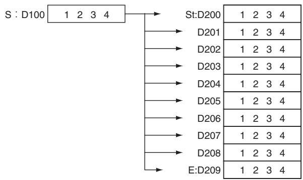
XCHG
| Instruction | Mnemonic | Variations | Function code | Function |
| DATA EXCHANGE | XCHG | @XCHG | 073 | Exchanges the contents of the two specified words. |
| Symbol | XCHG |
| XCHG(073) | |
| E1 | |
| E2 |
Applicable Program Areas
| Area | Step program areas | Subroutines | Interrupt tasks |
| Usage | OK | OK | OK |
Operands
| Operand | Description | Data type | Size |
| E1 | First exchange word | WORD | 1 |
| E2 | Second exchange word | WORD | 1 |
- Operand Specifications
| Area | Word addresses | Indirect DM addresses | Constants | CF | Pulse bits | TR bits | |||||||
| CIO | WR | HR | AR | T | C | DM | @DM | *DM | |||||
| E1,E2 | OK | OK | OK | OK | OK | OK | OK | OK | OK | --- | --- | --- | --- |
Flags
| Name | Label | Operation |
| Error Flag | P_ER | Unchanged |
| Equals Flag | P_EQ | Unchanged |
| Negative Flag | P_N | Unchanged |
Function
XCHG(073) exchanges the contents of E1 and E2.

Hint
To exchange 3 or more words, use XFER(070) to transfer the words to a third set of words (a buffer) as shown in this diagram.
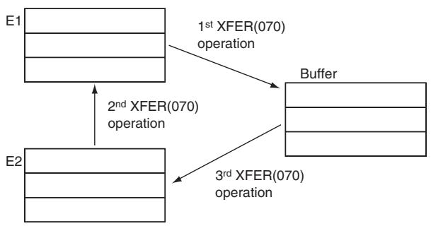
Sample program
When CIO 0.00 is ON in this example, the content of D100 is exchanged with the content of D200.
DIST
| Instruction | Mnemonic | Variations | Function code | Function |
| SINGLE WORD DISTRIBUTE | DIST | @DIST | 080 | Transfers the source word to a destination word calculated by adding an offset value to the base address. |
| Symbol | DIST | |
| —|—|—|—|—|—|—|—|—|—|—|—|—|—|—|—|—|—|—|—|—|—|—|—|—|—|—|—|—|—|—|—|—|—|—|—|—|—|—|—|—|—|—|—|—|—|—|—|—|—|— | S: Source word Bs: Destination base address Of: Offset | |
Applicable Program Areas
| Area | Step program areas | Subroutines | Interrupt tasks |
| Usage | OK | OK | OK |
Operands
| Operand | Description | Data type | Size |
| S | Source word | WORD | 1 |
| Bs | Destination base address | WORD | 1 |
| Of | Offset | UINT | 1 |
Bs: Destination Base Address
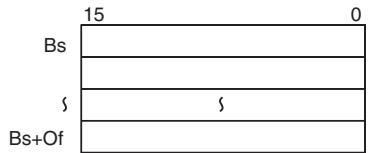
Of: Offset
The offset can be any value from 0000 to FFFF (0 to 65,535 decimal).
Note Bs and Bs+Of must be in the same data area.
- Operand Specifications
| Area | Word addresses | Indirect DM addresses | Constants | CF | Pulse bits | TR bits | |||||||
| CIO | WR | HR | AR | T | C | DM | @DM | *DM | |||||
| S | OK | OK | OK | OK | OK | OK | OK | OK | OK | OK | --- | --- | --- |
| Bs | --- | ||||||||||||
| Of | OK | ||||||||||||
Flags
| Name | Label | Operation |
| Error Flag | P_ER | OFF |
| Equals Flag | P_EQ | ON if the source data is 0000. OFF in all other cases. |
| Negative Flag | P_N | ON if the leftmost bit of the source data is 1. OFF in all other cases |
Function
DIST(080) copies S to the destination word calculated by adding Of to Bs.
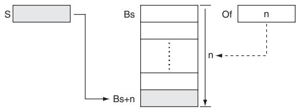
Hint
The same DIST(080) instruction can be used to distribute the source word to various words in the data area by changing the value of Of.
Precautions
Be sure that the offset does not exceed the end of the data area, i.e., Bs and Bs+Of are in the same data area.
Sample program
When CIO 0.00 is ON in this example, the contents of D100 will be copied to D210 (D200 + 10) if the contents of D300 is 10 (0A hexadecimal). The contents of D100 can be copied to other words by changing the offset in D300.
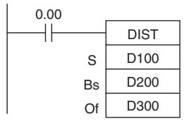
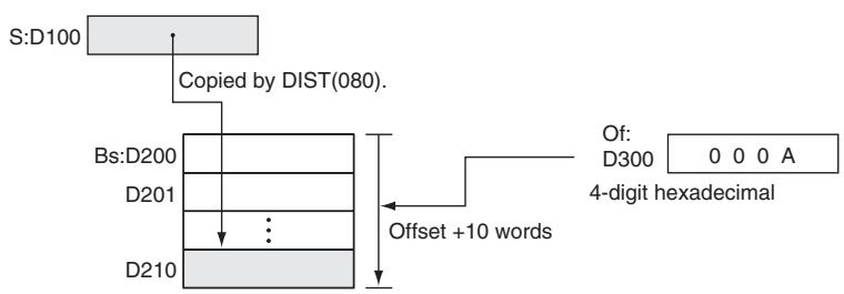
COLL
| Instruction | Mnemonic | Variations | Function code | Function |
| DATA COLLECT | COLL | @COLL | 081 | Transfers the source word (calculated by adding an offset value to the base address) to the desti-nation word. |
| Symbol | COLL | |
| COLL(081) | ||
| Bs | Bs: Source base address | |
| Of | Of: Offset | |
| D | D: Destination word | |
Applicable Program Areas
| Area | Step program areas | Subroutines | Interrupt tasks |
| Usage | OK | OK | OK |
Operands
| Operand | Description | Data type | Size |
| Bs | Source base address | WORD | 1 |
| Of | Offset | WORD | 1 |
| D | Destination word | WORD | 1 |
Bs: Source Base Address
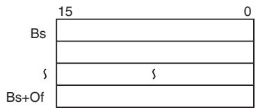
Of: Offset
The offset can be any value from 0000 to FFFF (0 to 65,535 decimal).
Note Bs and Bs+Of must be in the same data area.
- Operand Specifications
| Area | Word addresses | Indirect DM addresses | Constants | CF | Pulse bits | TR bits | |||||||
| CIO | WR | HR | AR | T | C | DM | @DM | *DM | |||||
| Bs | OK | OK | OK | OK | OK | OK | OK | OK | OK | --- | --- | --- | --- |
| Of | OK | ||||||||||||
| D | --- | ||||||||||||
Flags
| Name | Label | Operation |
| Error Flag | P_ER | OFF |
| Equals Flag | P_EQ | ON if the source data is 0000. OFF in all other cases. |
| Negative Flag | P_N | ON if the leftmost bit of the source data is 1. OFF in all other cases |
Function
COLL(081) copies the source word (calculated by adding Of to Bs) to the destination word.
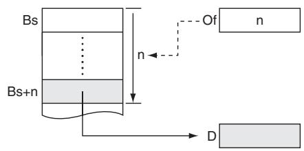
Hint
The same COLL(081) instruction can be used to collect data from various source words in the data area by changing the value of Of.
Precautions
Be sure that the offset does not exceed the end of the data area, i.e., Bs and Bs+Of are in the same data area.
Sample program
When CIO 0.00 is ON in the following example, the contents of D110 (D100 + 10) will be copied to D300 if the content of D200 is 10 (0A hexadecimal). The contents of other words can be copied to D300 by changing the offset in D200.
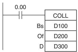
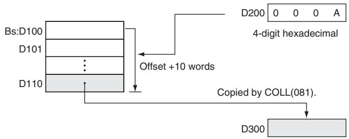
Data Shift Instructions
SFT
| Instruction | Mnemonic | Variations | Function code | Function |
| SHIFT REGISTER | SFT | --- | 010 | Operates a shift register. |
| Symbol | SFT | ||
| —| Data input Shift input Reset input | | SFT(010) St E | —| St: Starting word E: End word | |
Applicable Program Areas
| Area | Step program areas | Subroutines | Interrupt tasks |
| Usage | OK | OK | OK |
Operands
| Operand | Description | Data type | Size |
| St | Starting word | UINT | Variable |
| E | End word | UINT | Variable |
- Operand Specifications
| Area | Word addresses | Indirect DM addresses | Constants | CF | Pulse bits | TR bits | |||||||
| CIO | WR | HR | AR | T | C | DM | @DM | *DM | |||||
| St,E | OK | OK | OK | --- | --- | --- | --- | --- | --- | --- | --- | --- | --- |
Flags
| Name | Label | Operation |
| Error Flag | P_ER | OFF |
Function
- When the execution condition on the shift input changes from OFF to ON, all the data from St to E is shifted to the left by one bit (from the rightmost bit to the leftmost bit), and the ON/OFF status of the data input is placed in the rightmost bit.
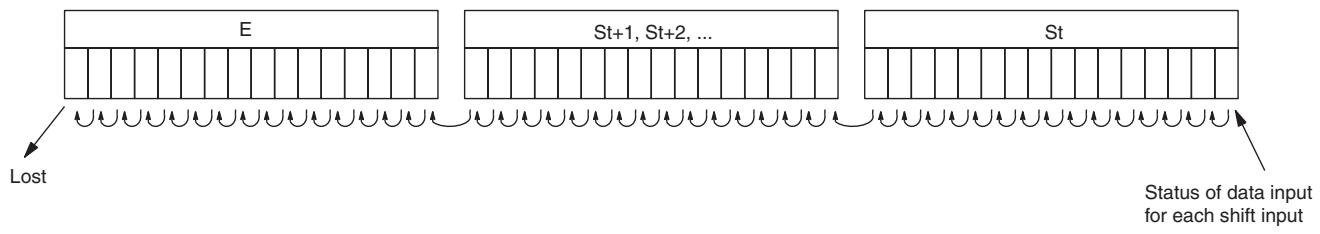
Precautions
- Do not use more than one SFT(010) instructions with overlapping shift words. The results will not be dependable.
- St and E must be in the same data area.
- The bit data shifted out of the shift register is discarded.
- When the reset input turns ON, all bits in the shift register from the rightmost designated word (St) to the leftmost designated word (E) will be reset (i.e., set to 0). The reset input takes priority over other inputs.
- St must be less than or equal to E, but even when St is set to greater than E an error will not occur and one word of data in St will be shifted.
Sample program
- Shift Register Exceeding 16 Bits
The following example shows a 48-bit shift register using words CIO 128 to CIO 130. A 1-s clock pulse is used so that the execution condition produced by CIO 0.05 is shifted into a 3-word register between CIO 128.00 and CIO 130.15 every second.
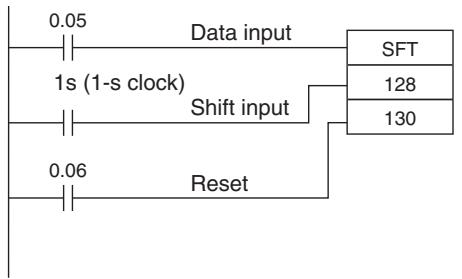
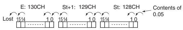
SFTR
| Instruction | Mnemonic | Variations | Function code | Function |
| REVERSIBLE SHIFT REGIS-TER | SFTR | @SFTR | 084 | Creates a shift register that shifts data to either the right or the left. |
| Symbol | SFTR | |
| SFTR(084) | ||
| C | C: Control word | |
| St | St: Starting word | |
| E | E: End word | |
Applicable Program Areas
| Area | Step program areas | Subroutines | Interrupt tasks |
| Usage | OK | OK | OK |
Operands
| Operand | Description | Data type | Size |
| C | Control word | UINT | 1 |
| St | Starting word | UINT | Variable |
| E | End word | UINT | Variable |
C: Control Word
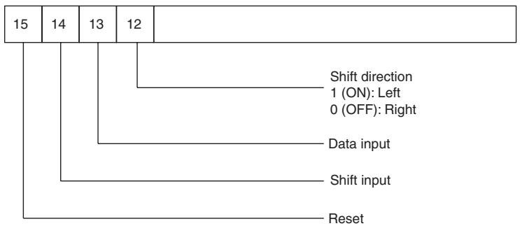
Note St and E must be in the same data area.
-Operand Specifications
| Area | Word addresses | Indirect DM addresses | Constants | CF | Pulse bits | TR bits | |||||||
| CIO | WR | HR | AR | T | C | DM | @DM | *DM | |||||
| C,St,E | OK | OK | OK | OK | OK | OK | OK | OK | OK | --- | --- | --- | --- |
Flags
| Name | Label | Operation |
| Error Flag | P_ER | ON when St is greater than EOFF in all other cases. |
| Carry Flag | P_CY | ON when 1 is shifted into it.OFF when 0 is shifted into it.OFF when reset is set to 1. |
Function
When the execution condition of the shift input bit (bit 14 of C) changes to ON, all the data from St to E is moved in the designated shift direction (designated by bit 12 of C) by 1 bit, and the ON/OFF status of the data input is placed in the rightmost or leftmost bit. The bit data shifted out of the shift register is placed in the Carry Flag (CY)

Note - The above shift operations are applicable when the reset bit (bit 15 of C) is set to OFF.
- When reset (bit 15 of C) turns ON all bits in the shift register, from St to E will be reset (i.e., set to 0).
Sample program
- Shifting Data
If shift input W0.14 goes ON when CIO 0.00 is ON, and the reset bit W0.15 is OFF, words CIO 100 through CIO 102 will shift one bit in the direction designated by W0.12 (e.g., 1: Right) and the contents of input bit W0.13 will be shifted into the rightmost bit, CIO 100.00. The contents of CIO 102.15 will be shifted to the Carry Flag (CY).
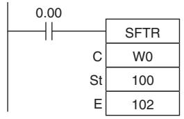
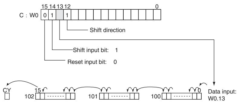
- Resetting Data
If W0.14 is ON when CIO 0.00 is ON, and the reset bit, W0.15, is ON, words CIO 100 through CIO 102 and the Carry Flag will be reset to OFF.
- Controlling Data
Resetting Data
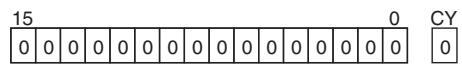
Shifting Data Left (from Rightmost to Leftmost Bit)
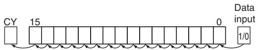
Shifting Data Right (from Leftmost to Rightmost Bit)
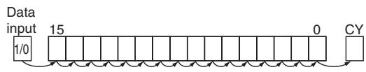
All bits from St to E and the Carry Flag are set to 0 and no other data can be received when the reset input bit (bit 15 of C) is ON.
When the shift input bit (bit 14 of C) is ON, the contents of the input bit (bit 13 of C) is shifted to bit 00 of the starting word, and each bit thereafter is shifted one bit to the left. The status of bit 15 of the end word is shifted to the Carry Flag.
When the shift input bit (bit 14 of C) is ON, the contents of the input bit (bit 13 of C) (I/O) is shifted to bit 15 on the end word, and each bit thereafter is shifted one bit to the right. The status of bit 00 of the starting word is shifted to the Carry Flag.
WSFT
| Instruction | Mnemonic | Variations | Function code | Function |
| WORD SHIFT | WSFT | @WSFT | 016 | Shifts data between St and E in word units. |
| Symbol | WSFT | |
| —|—|—|—|—|—|—|—|—|—|—|—|—|—|—|—|—|—|—|—|—|—|—|—|—|—|—|—|—|—|—|—|—|—|—|—|—|—|—|—|—|—|—|—|—|—|—|—|—|—|— | WSFT(016) | |
| S | S: Source word | |
| St | St: Starting word | |
| E | E: End word | |
Applicable Program Areas
| Area | Step program areas | Subroutines | Interrupt tasks |
| Usage | OK | OK | OK |
Operands
| Operand | Description | Data type | Size |
| S | Control word | WORD | 1 |
| St | Starting word | UINT | Variable |
| E | End word | UINT | Variable |
- Operand Specifications
| Area | Word addresses | Indirect DM addresses | Constants | CF | Pulse bits | TR bits | |||||||
| CIO | WR | HR | AR | T | C | DM | @DM | *DM | |||||
| S | OK | OK | OK | OK | OK | OK | OK | OK | OK | OK | --- | --- | --- |
| St,E | --- | ||||||||||||
Flags
| Name | Label | Operation |
| Error Flag | P_ER | ON when St is greater than EOFF in all other cases. |
Function
WSFT(016) shifts data from St to E in word units and the data from the source word S is places into St. The contents of E is lost.
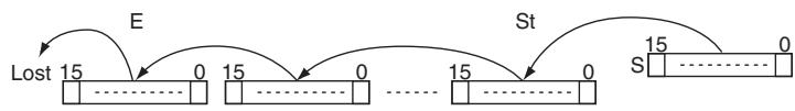
Precautions
- St and E must be in the same data area.
- When large amounts of data are shifted, the instruction execution time is quite long. Be sure that the power is not cut while WSFT(016) is being executed, causing the shift operation to stop halfway through.
Sample program
When CIO 0.00 is ON, data from CIO 100 through CIO 102 will be shifted one word toward E. The contents of W0 will be stored in CIO 100 and the contents of CIO 102 will be lost.
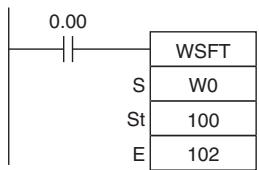
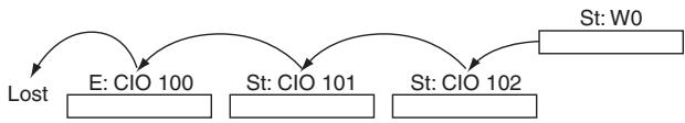
ASL
| Instruction | Mnemonic | Variations | Function code | Function |
| ARITHMETIC SHIFT LEFT | ASL | @ASL | 025 | Shifts the contents of Wd one bit to the left. |
| Symbol | ASL |
| — ASL(025) — Wd Wd: Word |
Applicable Program Areas
| Area | Step program areas | Subroutines | Interrupt tasks |
| Usage | OK | OK | OK |
Operands
| Operand | Description | Data type | Size |
| Wd | Word | UINT | 1 |
-Operand Specifications
| Area | Word addresses | Indirect DM addresses | Constants | CF | Pulse bits | TR bits | |||||||
| CIO | WR | HR | AR | T | C | DM | @DM | *DM | |||||
| Wd | OK | OK | OK | OK | OK | OK | OK | OK | OK | --- | --- | --- | --- |
Flags
| Name | Label | Operation |
| Error Flag | P_ER | OFF |
| Equals Flag | P_EQ | ON when the shift result is 0. OFF in all other cases. |
| Carry Flag | P_CY | ON when 1 is shifted into the Carry Flag (CY). OFF in all other cases. |
| Negative Flag | P_N | ON when the leftmost bit is 1 as a result of the shift. OFF in all other cases. |
Function
ASL(025) shifts the contents of Wd one bit to the left (from rightmost bit to leftmost bit). "0" is placed in the rightmost bit and the data from the leftmost bit is shifted into the Carry Flag (CY).
Sample program
When CIO 0.00 is ON, CIO 100 will be shifted one bit to the left. "0" will be placed in CIO 100.00 and the contents of CIO 100.15 will be shifted to the Carry Flag (CY).
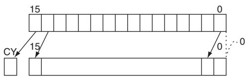
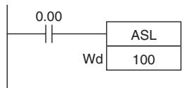
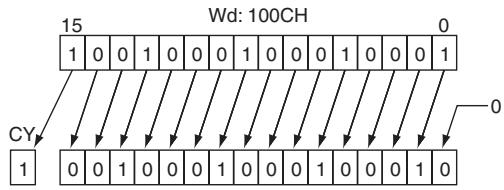
ASR
| Instruction | Mnemonic | Variations | Function code | Function |
| ARITHMETIC SHIFT RIGHT | ASR | @ASL | 026 | Shifts the contents of Wd one bit to the right. |
| Symbol | ASR | |
| — | ASR(026) — | |
| Wd Wd: Word | ||
Applicable Program Areas
| Area | Step program areas | Subroutines | Interrupt tasks |
| Usage | OK | OK | OK |
Operands
| Operand | Description | Data type | Size |
| Wd | Word | UINT | 1 |
-Operand Specifications
| Area | Word addresses | Indirect DM addresses | Constants | CF | Pulse bits | TR bits | |||||||
| CIO | WR | HR | AR | T | C | DM | @DM | *DM | |||||
| Wd | OK | OK | OK | OK | OK | OK | OK | OK | OK | --- | --- | --- | --- |
Flags
| Name | Label | Operation |
| Error Flag | P_ER | OFF |
| Equals Flag | P_EQ | ON when the shift result is 0. OFF in all other cases. |
| Carry Flag | P_CY | ON when 1 is shifted into the Carry Flag (CY). OFF in all other cases. |
| Negative Flag | P_N | OFF |
Function
ASR(026) shifts the contents of Wd one bit to the right (from leftmost bit to rightmost bit). "0" will be placed in the leftmost bit and the contents of the rightmost bit will be shifted into the Carry Flag (CY).
Sample program
When CIO 0.00 is ON, word CIO 100 will shift one bit to the right. "0" will be placed in CIO 100.15 and the contents of CIO 100.00 will be shifted to the Carry Flag (CY).
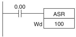

ROL
| Instruction | Mnemonic | Variations | Function code | Function |
| ROTATE LEFT | ROL | @ROL | 027 | Shifts all Wd bits one bit to the left including the Carry Flag (CY). |
| Symbol | ROL | |
| —| —— | ROL(027) —— | |
| Wd Wd: Word | ||
Applicable Program Areas
| Area | Step program areas | Subroutines | Interrupt tasks |
| Usage | OK | OK | OK |
Operands
| Operand | Description | Data type | Size |
| Wd | Word | UINT | 1 |
- Operand Specifications
| Area | Word addresses | Indirect DM addresses | Constants | CF | Pulse bits | TR bits | |||||||
| CIO | WR | HR | AR | T | C | DM | @DM | *DM | |||||
| Wd | OK | OK | OK | OK | OK | OK | OK | OK | OK | --- | --- | --- | --- |
Flags
| Name | Label | Operation |
| Error Flag | P_ER | OFF |
| Equals Flag | P_EQ | ON when the shift result is 0. OFF in all other cases. |
| Carry Flag | P_CY | ON when 1 is shifted into the Carry Flag (CY). OFF in all other cases. |
| Negative Flag | P_N | ON when the leftmost bit is 1 as a result of the shift. OFF in all other cases. |
Function
ROL(027) shifts all bits of Wd including the Carry Flag (CY) to the left (from rightmost bit to leftmost bit).
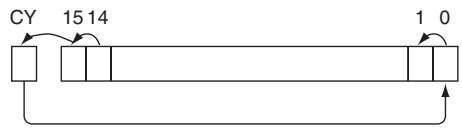
Hint
It is possible to set the Carry Flag contents to 1 or 0 immediately before executing this instruction, by using the Set Carry (STC(040)) or Clear Carry (CLC(041)) instructions.
Sample program
When CIO 0.00 is ON, word CIO 100 and the Carry Flag (CY) will shift one bit to the left. The contents of CIO 100.15 will be shifted to the Carry Flag (CY) and the Carry Flag contents will be shifted to CIO 100.00.
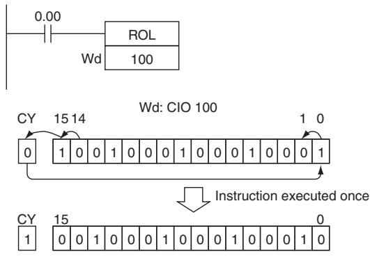
ROR
| Instruction | Mnemonic | Variations | Function code | Function |
| ROTATE RIGHT | ROR | @ROR | 028 | Shifts all Wd bits one bit to the right including the Carry Flag (CY). |
| Symbol | ROR | |
| —|— | ROR(028) —|— | |
| Wd Wd: Word | ||
Applicable Program Areas
| Area | Step program areas | Subroutines | Interrupt tasks |
| Usage | OK | OK | OK |
Operands
| Operand | Description | Data type | Size |
| Wd | Word | UINT | 1 |
- Operand Specifications
| Area | Word addresses | Indirect DM addresses | Constants | CF | Pulse bits | TR bits | |||||||
| CIO | WR | HR | AR | T | C | DM | @DM | *DM | |||||
| Wd | OK | OK | OK | OK | OK | OK | OK | OK | OK | --- | --- | --- | --- |
Flags
| Name | Label | Operation |
| Error Flag | P_ER | OFF |
| Equals Flag | P_EQ | ON when the shift result is 0. OFF in all other cases. |
| Carry Flag | P_CY | ON when 1 is shifted into the Carry Flag (CY). OFF in all other cases. |
| Negative Flag | P_N | ON when the leftmost bit is 1 as a result of the shift. OFF in all other cases. |
Function
ROR(028) shifts all bits of Wd including the Carry Flag (CY) to the right (from leftmost bit to rightmost bit).
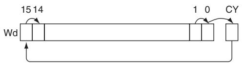
Hint
It is possible to set the Carry Flag contents to 1 or 0 immediately before executing this instruction, by using the Set Carry (STC(040)) or Clear Carry (CLC(041)) instructions.
Sample program
When CIO 0.00 is ON, word CIO 100 and the Carry Flag (CY) will shift one bit to the right. The contents of CIO 100.00 will be shifted to the Carry Flag (CY) and the Carry Flag contents will be shifted to CIO 100.15.
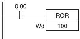
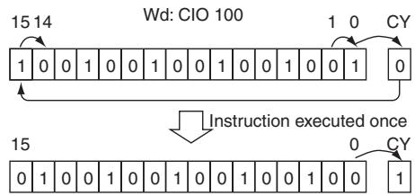
SLD/SRD
| Instruction | Mnemonic | Variations | Function code | Function |
| ONE DIGIT SHIFT LEFT | SLD | @SLD | 074 | Shifts data by one digit (4 bits) to the left. |
| ONE DIGIT SHIFT RIGHT | SRD | @SRD | 075 | Shifts data by one digit (4 bits) to the right. |
| Symbol | SLD | SRD | ||
| SLD(074) | St: Starting WordE: End word | SRD(075) | St: Starting WordE: End word | |
| St | St | |||
| E | E | |||
Applicable Program Areas
| Area | Step program areas | Subroutines | Interrupt tasks |
| Usage | OK | OK | OK |
Operands
| Operand | Description | Data type | Size |
| St | Starting Word | UINT | Variable |
| E | End Word | UINT | Variable |
- Operand Specifications
| Area | Word addresses | Indirect DM addresses | Constants | CF | Pulse bits | TR bits | |||||||
| CIO | WR | HR | AR | T | C | DM | @DM | *DM | |||||
| St,E | OK | OK | OK | OK | OK | OK | OK | OK | OK | --- | --- | --- | --- |
Flags
| Name | Label | Operation |
| Error Flag | P_ER | ON when St is greater than EOFF in all other cases. |
Function
SLD
SLD(074) shifts data between St and E by one digit (4 bits) to the left. "0" is placed in the rightmost digit (bits 3 to 0 of St), and the content of the leftmost digit (bits 15 to 12 of E) is lost.
SRD
SRD(075) shifts data between St and E by one digit (4 bits) to the right. "0" is placed in the leftmost digit (bits 15 to 12 of E), and the content of the rightmost digit (bits 3 to 0 of St) is lost.
Precautions
- St and E must be in the same data area.
- When large amounts of data are shifted, the instruction execution time is quite long. Be sure that the power is not cut while SLD(074) and SRD(075) is being executed, causing the shift operation to stop halfway through.
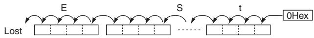
■SLD
■SRD
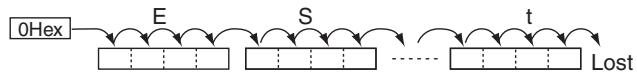
Sample program
SLD
When CIO 0.00 is ON, words CIO 100 through CIO 102 will shift by one digit (4 bits) to the left. A zero will be placed in bits 0 to 3 of word CIO 100 and the contents of bits 12 to 15 of CIO 102 will be lost.
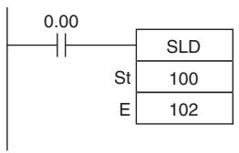
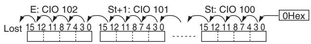
SRD
When CIO 0.00 is ON, words CIO 100 through CIO 102 will shift by one digit (4 bits) to the right. A zero will be placed in bits 12 to 15 of CIO 102 and the contents of bits 0 to 3 of word CIO 100 will be lost.
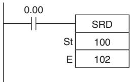
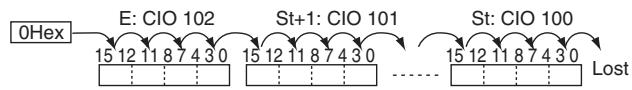
NASL/NSLL
| Instruction | Mnemonic | Variations | Function code | Function |
| SHIFT N-BITS LEFT | NASL | @NASL | 580 | Shifts the specified 16 bits of word data to the left by the specified number of bits. |
| DOUBLE SHIFT N-BITS LEFT | NSLL | @NSLL | 582 | Shifts the specified 32 bits of word data to the left by the specified number of bits. |
| Symbol | NASL | NSLL | ||
| —|—|—|—|—|—|—|—|—|—|—|—|—|—|—|—|—|—|—|—|—|—|—|—|—|—|—|—|—|—|—|—|—|—|—|—|—|—|—|—|—|—|—|—|—|—|—|—|—|—|— | —|—|—|—|—|—|—|—|—|—|—|—|—|—|—|—|—|—|—|—|—|—|—|—|—|—|—|—|—|—|—|—|—|—|—|—|—|—|—|—|—|—|—|—|—|—|—|—|—|− | —|—|—|—|—|—|—|—|—|—|—|—|—|—|—|—|—|—|—|—|—|—|—|—|—|—|—|—|—|—|—|—|—|—|—|—|—|—|—|—|—|—|—|—|—|—|—|—|—|0 | —|—|—|—|—|—|—|—|—|—|—|—|—|—|—|—|—|—|—|—|—|—|—|—|—|—|—|—|—|—|—|—|—|—|—|—|—|—|—|—|—|—|—|—|—|—|—|—|—|3 | |
Applicable Program Areas
| Area | Step program areas | Subroutines | Interrupt tasks |
| Usage | OK | OK | OK |
Operands
| Operand | Description | Data type | Size | ||
| NASL | NSLL | NASL | NSLL | ||
| D | Shift Word | UINT | UDINT | 1 | 2 |
| C | Control word | UINT | UDINT | 1 | 1 |
C: Control word
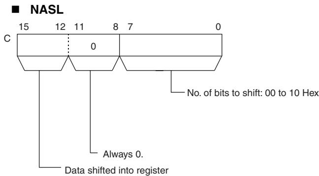
0 Hex: 0 shifted in
8 Hex: Contents of rightmost bit shifted in
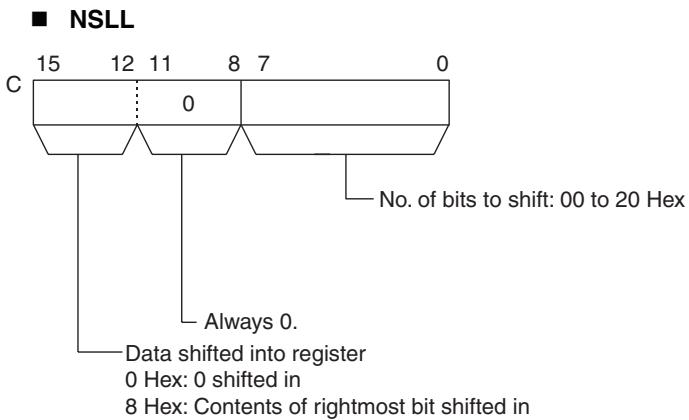
- Operand Specifications
| Area | Word addresses | Indirect DM addresses | Constants | CF | Pulse bits | TR bits | |||||||
| CIO | WR | HR | AR | T | C | DM | @DM | *DM | |||||
| D | OK | OK | OK | OK | OK | OK | OK | OK | OK | --- | --- | --- | --- |
| C | OK | OK | OK | OK | OK | OK | OK | OK | OK | OK | --- | --- | --- |
Flags
| Name | Label | Operation |
| Error Flag | P_ER | ON when the control word C (the number of bits to shift) is not within range.OFF in all other cases. |
| Equals Flag | P_EQ | ON when the shift result is 0.OFF in all other cases. |
| Carry Flag | P_CY | ON when 1 is shifted into the Carry Flag (CY).OFF in all other cases. |
| Negative Flag | P_N | ON when the leftmost bit is 1 as a result of the shift.OFF in all other cases. |
Function
- NASL
NASL(580) shifts D (the shift word) by the specified number of binary bits (specified in C) to the left (from the rightmost bit to the leftmost bit). Either zeros or the value of the rightmost bit will be placed into the specified number of bits of the shift word starting from the rightmost bit.
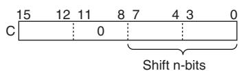
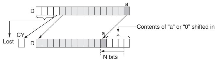
NSLL
NSLL(582) shifts D and D + 1 (the shift words) by the specified number of binary bits (specified in C) to the left (from the rightmost bit to the leftmost bit). Either zeros or the value of the rightmost bit will be placed into the specified number of bits of the shift word starting from the rightmost bit.
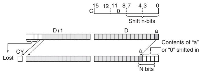
Precautions
- For any bits which are shifted outside the specified word, the contents of the last bit is shifted to the Carry Flag (CY), and all other data is lost.
- When the number of bits to shift (specified in C) is "0," the data will not be shifted. The appropriate flags will turn ON and OFF, however, according to data in the specified word.
Sample program
When CIO 0.00 is ON, The contents of CIO 100 is shifted 10 bits to the left (from the rightmost bit to the leftmost bit). The number of bits to shift is specified in bits 0 to 7 of word W0 (control data). The contents of bit 0 of CIO 100 is copied into bits from which data was shifted and the contents of the rightmost bit which was shifted out of range is shifted into the Carry Flag (CY). All other data is lost.
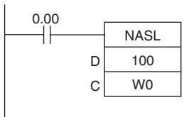
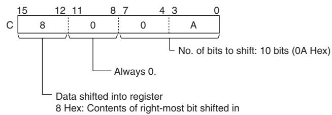
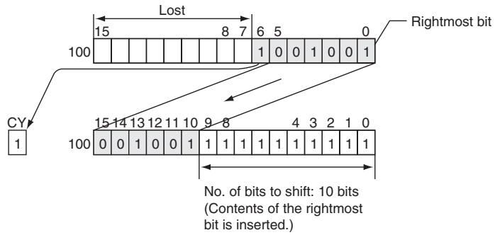
When CIO 0.00 is ON, CIO 100 and CIO 101 will be shifted to the left (from the rightmost bit to the left-most bit) by 10 bits. The number of bits to shift is specified in bits 0 to 7 of W0 (control data). The contents of bit 0 of CIO 100 is copied into bits from which data was shifted and the contents of the rightmost bit which was shifted out of range is shifted into the Carry Flag (CY). All other data is lost.
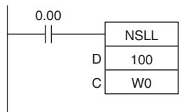
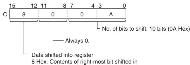
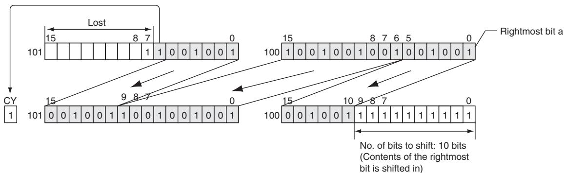
NASR/NSRL
| Instruction | Mnemonic | Variations | Function code | Function |
| SHIFT N-BITS RIGHT | NASR | @NASR | 581 | Shifts the specified 16 bits of word data to the right by the specified number of bits. |
| DOUBLE SHIFT N-BITS RIGHT | NSRL | @NSRL | 583 | Shifts the specified 32 bits of word data to the right by the specified number of bits. |
| Symbol | NASR | NSRL | ||||
| — | — | — | — | — | — | |
| NASR(581) | — | — | ||||
| D | D: Shift word | D | D: Shift word | |||
| C | C: Control word | C | C: Control word | |||
Applicable Program Areas
| Area | Step program areas | Subroutines | Interrupt tasks |
| Usage | OK | OK | OK |
Operands
| Operand | Description | Data type | Size | ||
| NASR | NSRL | NASR | NSRL | ||
| D | Shift Word | UINT | UDINT | 1 | 2 |
| C | Control word | UINT | UDINT | 1 | 1 |
C: Control word
NASR
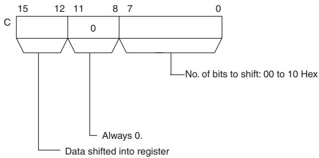
0 Hex: 0 shifted in
8 Hex: Contents of rightmost bit shifted in
NSRL
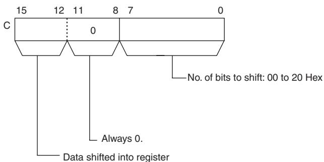
0 Hex: 0 shifted in
8 Hex: Contents of rightmost bit shifted in
-Operand Specifications
| Area | Word addresses | Indirect DM addresses | Constants | CF | Pulse bits | TR bits | |||||||
| CIO | WR | HR | AR | T | C | DM | @DM | *DM | |||||
| D | OK | OK | OK | OK | OK | OK | OK | OK | OK | --- | --- | --- | --- |
| C | OK | ||||||||||||
Flags
| Name | Label | Operation |
| Error Flag | P_ER | ON when the control word C (the number of bits to shift) is not within range.OFF in all other cases. |
| Equals Flag | P_EQ | ON when the shift result is 0OFF in all other cases. |
| Carry Flag | P_CY | ON when 1 is shifted into the Carry Flag (CY).OFF in all other cases. |
| Negative Flag | P_N | ON when the leftmost bit is 1 as a result of the shiftOFF in all other cases. |
Function
- NASR
NASR(581) shifts D (the shift word) by the specified number of binary bits (specified in C) to the right (from the rightmost bit to the leftmost bit). Either zeros or the value of the rightmost bit will be placed into the specified number of bits of the shift word starting from the rightmost bit.
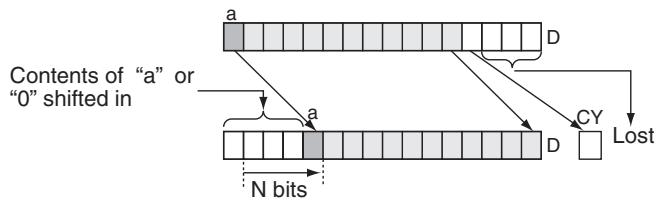
NSRL
NSRL(583) shifts D and D+1 (the shift words) by the specified number of binary bits (specified in C) to the right (from the leftmost bit to the rightmost bit). Either zeros or the value of the rightmost bit will be placed into the specified number of bits of the shift word starting from the rightmost bit.
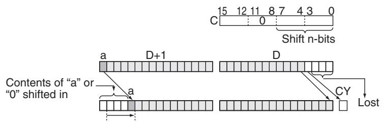
Precautions
- For any bits which are shifted outside the specified word, the contents of the last bit is shifted to the Carry Flag (CY), and all other data is discarded.
- When the number of bits to shift (specified in C) is "0," the data will not be shifted. The appropriate flags will turn ON and OFF, however, according to data in the specified word.
Sample program
- When CIO 0.00 is ON, CIO 100 will be shifted 10 bits to the right (from the leftmost bit to the rightmost bit). The number of bits to shift is specified in bits 0 to 7 of W0. The contents of bit 15 of CIO 100 is copied into the bits from which data was shifted and the contents of the leftmost bit of data which was shifted out of range, is shifted into the Carry Flag (CY). All other data is lost.
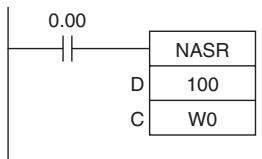
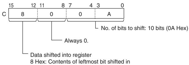
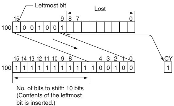
When CIO 0.00 is ON, CIO 100 and CIO 101 will be shifted 10 bits to the right (from the leftmost bit to the rightmost bit). The number of bits to shift is specified in bits 0 to 7 of W0 (control data). The contents of bit 15 of CIO will be copied into the bits from which data was shifted and the contents of the leftmost bit of data which was shifted out of range will be shifted into the Carry Flag (CY). All other data is lost.
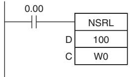
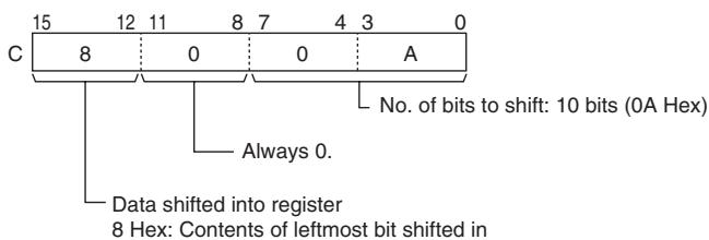
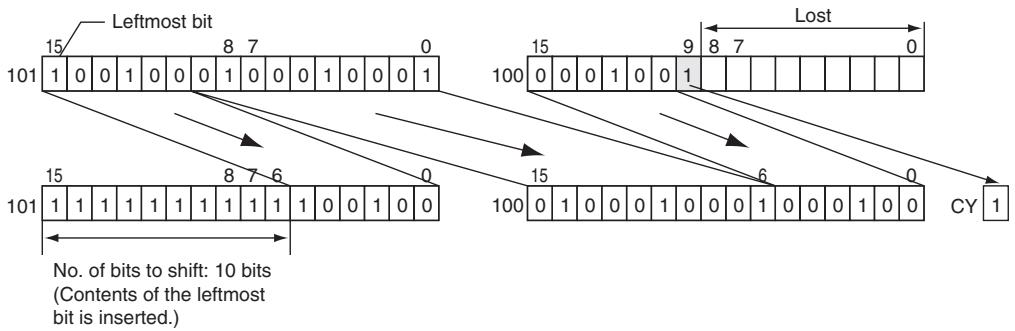
Increment/Decrement Instructions
$$ + + / + + L $$
| Instruction | Mnemonic | Variations | Function code | Function |
| INCREMENT BINARY | ++ | @++ | 590 | Increments the 4-digit hexadecimal content of the specified word by 1. |
| DOUBLE INIncrement BINARY | ++L | @++L | 591 | Increments the 8-digit hexadecimal content of the specified words by 1. |
| Symbol | ++ | ++L | ||
| —| |— | ++(590) Wd: Word | —| |— | ++L(591) Wd: First word | |
Applicable Program Areas
| Area | Step program areas | Subroutines | Interrupt tasks |
| Usage | OK | OK | OK |
Operands
| Operand | Description | Data type | Size | ||
| ++ | ++L | ++ | ++L | ||
| Wd | +: Word +: L: First word | UINT | UDINT | 1 | 2 |
- Operand Specifications
| Area | Word addresses | Indirect DM addresses | Constants | CF | Pulse bits | TR bits | |||||||
| CIO | WR | HR | AR | T | C | DM | @DM | *DM | |||||
| Wd | OK | OK | OK | OK | OK | OK | OK | OK | OK | --- | --- | --- | --- |
Flags
| Name | Label | Operation |
| Error Flag | P_ER | OFF |
| Equals Flag | P_EQ | ON if the result is 0000/0000 0000 after execution. OFF in all other cases. |
| Carry Flag | P_CY | ON if a digit in Wd/Wd+1 or Wd went from F to 0 during execution. OFF in all other cases. |
| Negative Flag | P_N | ON if bit 15 of Wd/Wd+1 is ON after execution. OFF in all other cases. |
Function
+ +
The ++(590) instruction adds 1 to the binary content of Wd. The specified word will be incremented by 1 every cycle as long as the execution condition of ++(590) is ON. When the up-differentiated variation of this instruction (@++(590)) is used, the specified word is incremented only when the execution condition has gone from OFF to ON.

+ + L
The ++L(591) instruction adds 1 to the 8-digit hexadecimal content of Wd+1 and Wd. The content of the specified words will be incremented by 1 every cycle as long as the execution condition of ++L(591) is ON. When the up-differentiated variation of this instruction (@++L(591)) is used, the content of the specified words is incremented only when the execution condition has gone from OFF to ON.

Sample program
Operation of + + (590) / + + L(591)
In the following example, the content of D100 will be incremented by 1 every cycle as long as CIO 0.00 is ON.
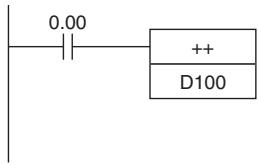
Incremented every cycle while CIO 0.00 is ON.
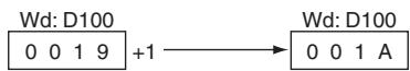
In the following example, the content of D100 will be incremented by 1 every cycle as long as CIO 0.00 is ON.
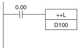
Incremented every cycle while CIO 0.00 is ON.
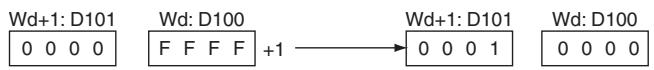
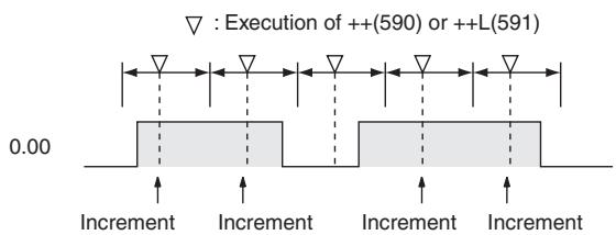
Operation of @++(590)/@++L(591)
The up-differentiated variation is used in the following example, so the content of D100 will be incremented by 1 only when CIO 0.00 has gone from OFF to ON.
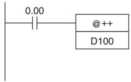
Incremented every cycle
while CIO 0.00 is ON.
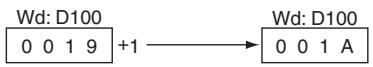
The up-differentiated variation is used in the following example, so the content of D101 and D100 will be incremented by 1 only when CIO 0.00 has gone from OFF to ON.
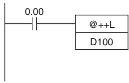
Incremented only for
up-differentiation.
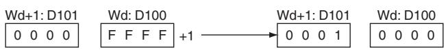
: Execution of @++(590) or @++L(591)
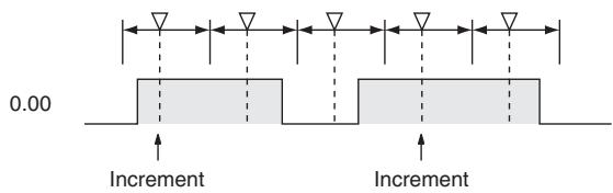

| Instruction | Mnemonic | Variations | Function code | Function |
| DECREMENT BINARY | -- | @@ | 592 | Decrement the 4-digit hexadecimal content of the specified word by 1. |
| DOUBLE DECREMENT BINARY | --L | @@L | 593 | Decrement the 8-digit hexadecimal content of the specified words by 1. |
| Symbol | -- | --L | ||
| --(592) Wd | --(592) Wd: Word | --(593) Wd | --L(593) Wd: First word | |
Applicable Program Areas
| Area | Step program areas | Subroutines | Interrupt tasks |
| Usage | OK | OK | OK |
Operands
| Operand | Description | Data type | Size | ||
| -- | --L | -- | --L | ||
| Wd | --- Word --L: First word | UINT | UDINT | 1 | 2 |
- Operand Specifications
| Area | Word addresses | Indirect DM addresses | Constants | CF | Pulse bits | TR bits | |||||||
| CIO | WR | HR | AR | T | C | DM | @DM | *DM | |||||
| Wd | OK | OK | OK | OK | OK | OK | OK | OK | OK | --- | --- | --- | --- |
Flags
| Name | Label | Operation |
| Error Flag | P_ER | OFF |
| Equals Flag | P_EQ | ON if the result is 0000/0000 0000 after execution. OFF in all other cases. |
| Carry Flag | P_CY | ON if a digit in Wd/Wd+1 or Wd went from 0 to F during execution. OFF in all other cases. |
| Negative Flag | P_N | ON if bit 15 of Wd/Wd+1 is ON after execution. OFF in all other cases. |
Function
The --(592) instruction subtracts 1 from the binary content of Wd. The specified word will be decremented by 1 every cycle as long as the execution condition of --(592) is ON. When the up-differentiated variation of this instruction (@ --(592)) is used, the specified word is decremented only when the execution condition has gone from OFF to ON.

The --L(593) instruction subtracts 1 from the 8-digit hexadecimal content of Wd+1 and Wd. The content of the specified words will be decremented by 1 every cycle as long as the execution condition of -- L(593) is ON. When the up-differentiated variation of this instruction (@--L(593)) is used, the content of the specified words is decremented only when the execution condition has gone from OFF to ON.

Sample program
Operation of --(592)/--L(593)
The up-differentiated variation is used in the following example, so the content of D100 will be decremented by 1 only when CIO 0.00 has gone from OFF to ON.
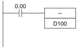
Decremented every cycle while CIO 0.00 is ON.
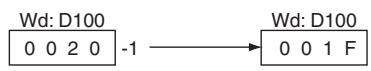
In the following example, the 8-digit hexadecimal content of D101 and D100 will be decremented by 1 every cycle as long as CIO 0.00 is ON.
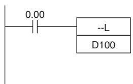
Decremented every cycle while CIO 0.00 is ON.
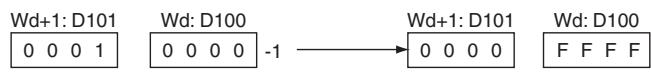
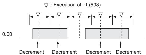
Operation of @--(592)/@@L(593)
In the following example, the content of D100 will be decremented by 1 every cycle as long as CIO 0.00 is ON.
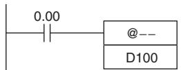
Decremented every cycle
while CIO 0.00 is ON.
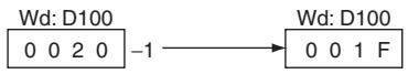
The up-differentiated variation is used in the following example, so the content of D101 and D100 will be decremented by 1 only when CIO 0.00 has gone from OFF to ON.
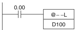
Decremented only for
up-differentiation.
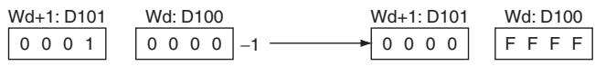
:Execution of @ - L(593)
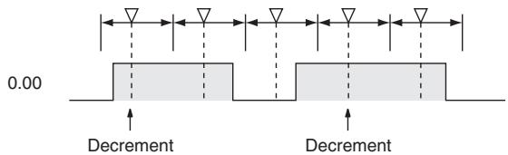
$$ + + \mathrm {B} / + + \mathrm {B L} $$
| Instruction | Mnemonic | Variations | Function code | Function |
| INCREMENT BCD | ++B | @ ++B | 594 | Increments the 4-digit BCD content of the speci-fied word by 1. |
| DOUBLE INIncrement BCD | ++BL | @ ++BL | 595 | Increments the 8-digit BCD content of the speci-fied words by 1. |
| Symbol | ++B | ++BL | ||
| + B(594) Wd | + B(594) Wd: Word | + B(595) Wd | + B(595) Wd: First word | |
Applicable Program Areas
| Area | Step program areas | Subroutines | Interrupt tasks |
| Usage | OK | OK | OK |
Operands
| Operand | Description | Data type | Size | ||
| ++ | ++L | ++ | ++L | ||
| Wd | ++B: Word | WORD | DWORD | 1 | 2 |
| ++BL: First word | |||||
- Operand Specifications
| Area | Word addresses | Indirect DM addresses | Constants | CF | Pulse bits | TR bits | |||||||
| CIO | WR | HR | AR | T | C | DM | @DM | *DM | |||||
| Wd | OK | OK | OK | OK | OK | OK | OK | OK | OK | --- | --- | --- | --- |
Flags
| Name | Label | Operation |
| Error Flag | P_ER | ON if the content of Wd/Wd+1 and Wd is not BCD. OFF in all other cases. |
| Equals Flag | P_EQ | ON if the result is 0000/0000 0000 after execution. OFF in all other cases. |
| Carry Flag | P_CY | ON if a digit in Wd/Wd+1 or Wd went from 9 to 0 during execution. OFF in all other cases. |
Function
+ + B
The ++B(594) instruction adds 1 to the BCD content of Wd. The specified word will be incremented by 1 every cycle as long as the execution condition of ++B(594) is ON. When the up-differentiated variation of this instruction (@++B(594)) is used, the specified word is incremented only when the execution condition has gone from OFF to ON.

+ + BL
The ++BL(595) instruction adds 1 to the 8-digit BCD content of Wd+1 and Wd. The content of the specified words will be incremented by 1 every cycle as long as the execution condition of ++BL(595) is ON. When the up-differentiated variation of this instruction (@++BL(595)) is used, the content of the specified words is incremented only when the execution condition has gone from OFF to ON.

Sample program
Operation of ++B(594)/++BL(595)
In the following example, the BCD content of D100 will be incremented by 1 every cycle as long as CIO 0.00 is ON.
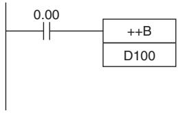
Incremented every cycle
while CIO 0.00 is ON.
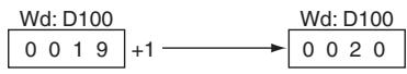
In the following example, the 8-digit BCD content of D101 and D100 will be incremented by 1 every cycle as long as CIO 0.00 is ON.
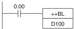
Incremented every cycle
while CIO 0.00 is ON.
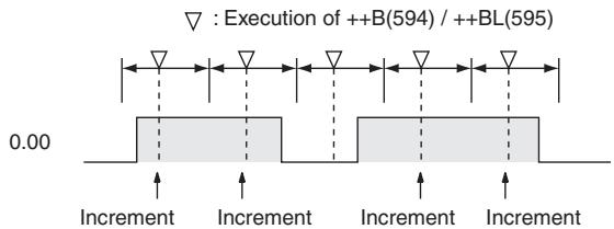
- Operation of @ ++B(594)/@ ++BL(595)
The up-differentiated variation is used in the following example, so the content of D100 will be incremented by 1 only when CIO 0.00 has gone from OFF to ON.
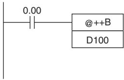
Incremented only for up-differentiation.
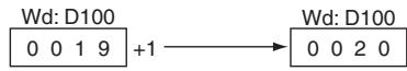
The up-differentiated variation is used in the following example, so the BCD content of D101 and D100 will be incremented by 1 only when CIO 0.00 has gone from OFF to ON.
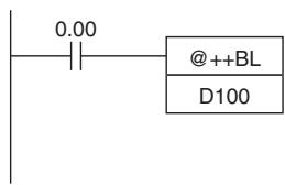
Incremented only for up-differentiation.
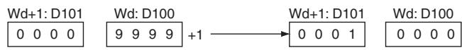
: Execution of @++B(594) or @++BL(595)
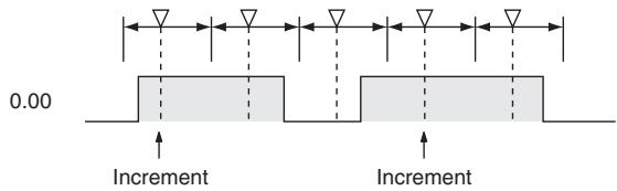
--B/--BL
| Instruction | Mnemonic | Variations | Function code | Function |
| DECREMENT BCD | --B | @@-B | 596 | Decrements the 4-digit BCD content of the speci-fied word by 1. |
| DOUBLE DECREMENT BCD | --BL | @@-BL | 597 | Decrements the 8-digit BCD content of the speci-fied words by 1. |
| Symbol | --B | --BL | ||
| —|— | —B(596) Wd: Word | —|— | —BL(597) Wd: First word | |
Applicable Program Areas
| Area | Step program areas | Subroutines | Interrupt tasks |
| Usage | OK | OK | OK |
Operands
| Operand | Description | Data type | Size | ||
| -- | --L | -- | --L | ||
| Wd | --B: Word | WORD | DWORD | 1 | 2 |
| --BL: First word | |||||
-Operand Specifications
| Area | Word addresses | Indirect DM addresses | Constants | CF | Pulse bits | TR bits | |||||||
| CIO | WR | HR | AR | T | C | DM | @DM | *DM | |||||
| Wd | OK | OK | OK | OK | OK | OK | OK | OK | OK | --- | --- | --- | --- |
Flags
| Name | Label | Operation |
| Error Flag | P_ER | ON if the content of Wd/Wd+1 and Wd is not BCD. OFF in all other cases. |
| Equals Flag | P_EQ | ON if the result is 0000/0000 0000 after execution. OFF in all other cases. |
| Carry Flag | P_CY | ON if a digit in Wd/Wd+1 or Wd went from 0 to 9 during execution. OFF in all other cases. |
Function
B
The --B(596) instruction subtracts 1 from the BCD content of Wd. The specified word will be decremented by 1 every cycle as long as the execution condition of --B(596) is ON. When the up-differentiated variation of this instruction (@--B(596)) is used, the specified word is decremented only when the execution condition has gone from OFF to ON.

- --BL
The --BL(597) instruction subtracts 1 from the 8-digit BCD content of Wd+1 and Wd. The content of the specified words will be decremented by 1 every cycle as long as the execution condition of --BL(597) is ON. When the up-differentiated variation of this instruction (@--BL(597)) is used, the content of the specified words is decremented only when the execution condition has gone from OFF to ON.

Sample program
Operation of --B(596)/--BL(597)
In the following example, the BCD content of D100 will be decremented by 1 every cycle as long as CIO 0.00 is ON.
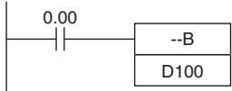
Decremented every cycle while CIO 0.00 is ON.
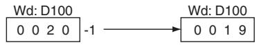
In the following example, the 8-digit BCD content of D101 and D100 will be decremented by 1 every cycle as long as CIO 0.00 is ON.
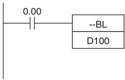
Decremented every cycle while CIO 0.00 is ON.
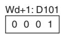
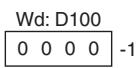
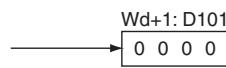
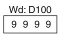

- Operation of @--B(596)/@@BL(597)
The up-differentiated variation is used in the following example, so the BCD content of D100 will be decremented by 1 only when CIO 0.00 has gone from OFF to ON.
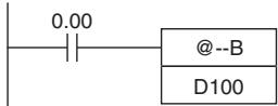
Decremented only for up-differentiation.
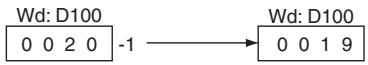
The up-differentiated variation is used in the following example, so the BCD content of D101 and D100 will be decremented by 1 only when CIO 0.00 has gone from OFF to ON.
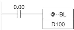
Decremented only for up-differentiation.
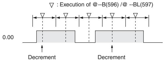
Symbol Math Instructions
+ / + L
| Instruction | Mnemonic | Variations | Function code | Function |
| SIGNED BINARY ADD WITHOUT CARRY | + | @+ | 400 | Adds 4-digit (single-word) hexadecimal data and/or constants. |
| DOUBLE SIGNED BINARY ADD WITHOUT CARRY | +L | @+L | 401 | Adds 8-digit (double-word) hexadecimal data and/or constants. |
| Symbol | + | +L | ||
| +(400)Au | Au: Augend wordAd: Addend wordR: Result word | +(401)Au | Au: 1st augend wordAd: 1st addend wordR: 1st result word | |
| Ad | R | |||
Applicable Program Areas
| Area | Step program areas | Subroutines | Interrupt tasks |
| Usage | OK | OK | OK |
Operands
| Operand | Description | Data type | Size | ||
| + | +L | + | +L | ||
| Au | +: Augend word | INT | DINT | 1 | 2 |
| +L: First augend word | |||||
| Ad | +: Addend word | INT | DINT | 1 | 2 |
| +L: First addend word | |||||
| R | +: Result word | INT | DINT | 1 | 2 |
| +L: First result word | |||||
- Operand Specifications
| Area | Word addresses | Indirect DM addresses | Constants | CF | Pulse bits | TR bits | |||||||
| CIO | WR | HR | AR | T | C | DM | @DM | *DM | |||||
| Au, Ad | OK | OK | OK | OK | OK | OK | OK | OK | OK | OK | --- | --- | --- |
| R | --- | ||||||||||||
Flags
| Name | Label | Operation | |
| + | +L | ||
| Error Flag | P_ER | OFF | OFF |
| Equals Flag | P_EQ | ON when the result is 0. OFF in all other cases. | ON when the result is 0. OFF in all other cases. |
| Carry Flag | P_CY | ON when the addition results in a carry. OFF in all other cases. | ON when the addition results in a carry. OFF in all other cases. |
| Overflow Flag | P_OF | ON when the result of adding two positive num- bers is in the range 8000 to FFFF hex. OFF in all other cases. | ON when the result of adding two positive num- bers is in the range 80000000 to FFFFFFFF hex. OFF in all other cases. |
| Underflow Flag | P_UF | ON when the result of adding two negative num- bers is in the range 0000 to 7FFF hex. OFF in all other cases. | ON when the result of adding two negative num- bers is in the range 00000000 to 7FFFFFFF hex. OFF in all other cases. |
| Negative Flag | P_N | ON when the leftmost bit of the result is 1. OFF in all other cases. | ON when the leftmost bit of the result is 1. OFF in all other cases. |
Function
• +
(+400) adds the binary values in Au and Ad and outputs the result to R.
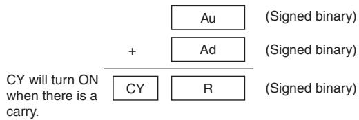
+L
+L(401) adds the binary values in Au and Au + 1 and Ad and Ad + 1 and outputs the result to R.
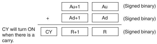
Sample program
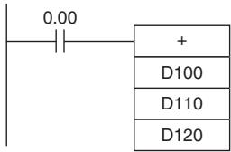
When CIO 0.00 is ON in this example, D100 and D110 will be added as 4-digit signed binary values and the result will be output to D120.

When CIO 0.00 is ON, D101 and D100 and D111 and D110 will be added as 8-digit signed binary values and the result will be output to D121 and D120.
+C/+CL
| Instruction | Mnemonic | Variations | Function code | Function |
| SIGNED BINARY ADD WITH CARRY | +C | @+C | 402 | Adds 4-digit (single-word) hexadecimal data and/or constants with the Carry Flag (CY). |
| DOUBLE SIGNED BINARY ADD WITH CARRY | +CL | @+CL | 403 | Adds 8-digit (double-word) hexadecimal data and/or constants with the Carry Flag (CY). |
| Symbol | +C | +CL | ||
| +C(402)Au | Au: Augend wordAd: Addend wordR: Result word | +CL(403)Au | Au: 1st augend wordAd: 1st addend wordR: 1st result word | |
| Ad | Ad | |||
| R | R | |||
Applicable Program Areas
| Area | Step program areas | Subroutines | Interrupt tasks |
| Usage | OK | OK | OK |
Operands
| Operand | Description | Data type | Size | ||
| +C | +CL | +C | +CL | ||
| Au | +C: Augend word | INT | DINT | 1 | 2 |
| +CL: First augend word | |||||
| Ad | +C: Addend word | INT | DINT | 1 | 2 |
| +CL: First addend word | |||||
| R | +C: Result word | INT | DINT | 1 | 2 |
| +CL: First result word | |||||
-Operand Specifications
| Area | Word addresses | Indirect DM addresses | Constants | CF | Pulse bits | TR bits | |||||||
| CIO | WR | HR | AR | T | C | DM | @DM | *DM | |||||
| Au, Ad | OK | OK | OK | OK | OK | OK | OK | OK | OK | OK | --- | --- | --- |
| R | --- | ||||||||||||
Flags
| Name | Label | Operation | |
| +C | +CL | ||
| Error Flag | P_ER | OFF | OFF |
| Equals Flag | P_EQ | ON when the addition result is 0. OFF in all other cases. | ON when the result is 0. OFF in all other cases. |
| Carry Flag | P_CY | ON when the addition results in a carry. OFF in all other cases. | ON when the results in a carry. OFF in all other cases. |
| Overflow Flag | P_OF | ON when the addition result of adding two positive numbers and CY is in the range 8000 to FFFF hex. OFF in all other cases. | ON when the result of adding two positive numbers and CY is in the range 80000000 to FFFFFFFF hex. OFF in all other cases. |
| Underflow Flag | P_UF | ON when the addition result of adding two negative numbers and CY is in the range 0000 to 7FFF hex. OFF in all other cases. | ON when the result of adding two negative numbers and CY is in the range 00000000 to 7FFFFFFF hex. OFF in all other cases. |
| Negative Flag | P_N | ON when the leftmost bit of the result is 1. OFF in all other cases. | ON when the leftmost bit of the result is 1. OFF in all other cases. |
Function
+C
+C(402) adds the binary values in Au, Ad, and CY and outputs the result to R.
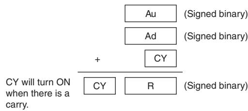
+CL
+CL(403) adds the binary values in Au and Au + 1 , Ad and Ad + 1 , and CY and outputs the result to R.
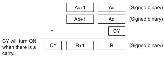
Hint
- To clear the Carry Flag (CY), execute the Clear Carry (CLC(041)) instruction.
Sample program
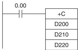
When CIO 0.00 is ON, D200, D210, and CY will be added as 4-digit signed binary values and the result will be output to D220.

When CIO 0.00 is ON, D201, D200, D211, D210, and CY will be added as 8-digit signed binary values, and the result will be output to D221 and D220.
+B/+BL
| Instruction | Mnemonic | Variations | Function code | Function |
| BCD ADD WITHOUT CARRY | +B | @+B | 404 | Adds 4-digit (single-word) BCD data and/or constants. |
| DOUBLE BCD ADD WITHOUT CARRY | +BL | @+BL | 405 | Adds 8-digit (double-word) BCD data and/or constants. |
| Symbol | +B | +BL | ||
| +B(404) | +B(405) | |||
| Au | Au: Augend word | Au | Au: 1st augend word | |
| Ad | Ad: Addend word | Ad | Ad: 1st addend word | |
| R | R: Result word | R | R: 1st result word | |
Applicable Program Areas
| Area | Step program areas | Subroutines | Interrupt tasks |
| Usage | OK | OK | OK |
Operands
| Operand | Description | Data type | Size | ||
| +B | +BL | +B | +BL | ||
| Au | +B: Augend word | WORD | DWORD | 1 | 2 |
| +BL: First augend word | |||||
| Ad | +B: Addend word | WORD | DWORD | 1 | 2 |
| +BL: First addend word | |||||
| R | +B: Result word | WORD | DWORD | 1 | 2 |
| +BL: First result word | |||||
- Operand Specifications
| Area | Word addresses | Indirect DM addresses | Constants | CF | Pulse bits | TR bits | |||||||
| CIO | WR | HR | AR | T | C | DM | @DM | *DM | |||||
| Au, Ad | OK | OK | OK | OK | OK | OK | OK | OK | OK | OK | --- | --- | --- |
| R | --- | ||||||||||||
Flags
| Name | Label | Operation | |
| +B | +BL | ||
| Error Flag | P_ER | • ON when Au is not BCD. • ON when Ad is not BCD. • OFF in all other cases. | • ON when Au, Au +1 is not BCD. • ON when Ad, Ad +1 is not BCD. • OFF in all other cases. |
| Equals Flag | P_EQ | • ON when the result is 0. • OFF in all other cases. | • ON when the result is 0. • OFF in all other cases. |
| Carry Flag | P_CY | • ON when the addition results in a carry. • OFF in all other cases. | • ON when the addition results in a carry. • OFF in all other cases. |
Function
+B
+B(404) adds the BCD values in Au and Ad and outputs the result to R.
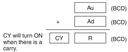
+BL
+BL(405) adds the BCD values in Au and Au + 1 and Ad and Ad + 1 and outputs the result to R, R + 1
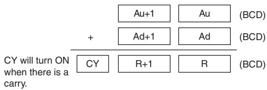
Sample program
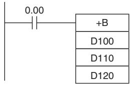
When CIO 0.00 is ON in the following example, D100 and D110 will be added as 4-digit BCD values, and the result will be output to D120.
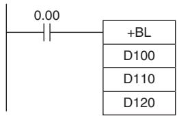
When CIO 0.00 is ON in the following example, D101 and D100 and D111 and D110 will be added as 8-digit BCD values, and the result will be output to D121 and D120.
+BC/+BCL
| Instruction | Mnemonic | Variations | Function code | Function |
| BCD ADD WITH CARRY | +BC | @ +BC | 406 | Adds 4-digit (single-word) BCD data and/or constants with the Carry Flag (CY). |
| DOUBLE BCD ADD WITH CARRY | +BCL | @ +BCL | 407 | Adds 8-digit (double-word) BCD data and/or constants with the Carry Flag (CY). |
| Symbol | +BC | +BCL | ||
| +BC(406) | +BCL(407) | |||
| Au | Au: Augend word | Au | Au: 1st augend word | |
| Ad | Ad: Addend word | Ad | Ad: 1st addend word | |
| R | R: Result word | R | R: 1st result word | |
Applicable Program Areas
| Area | Step program areas | Subroutines | Interrupt tasks |
| Usage | OK | OK | OK |
Operands
| Operand | Description | Data type | Size | ||
| +BC | +BCL | +BC | +BCL | ||
| Au | +BC: Augend word | WORD | DWORD | 1 | 2 |
| +BCL: First augend word | |||||
| Ad | +BC: Addend word | WORD | DWORD | 1 | 2 |
| +BCL: First addend word | |||||
| R | +BC: Result word | WORD | DWORD | 1 | 2 |
| +BCL: First result word | |||||
-Operand Specifications
| Area | Word addresses | Indirect DM addresses | Constants | CF | Pulse bits | TR bits | |||||||
| CIO | WR | HR | AR | T | C | DM | @DM | *DM | |||||
| Au, Ad | OK | OK | OK | OK | OK | OK | OK | OK | OK | OK | --- | --- | --- |
| R | --- | ||||||||||||
Flags
| Name | Label | Operation | |
| +BC | +BCL | ||
| Error Flag | P_ER | • ON when Au is not BCD. • ON when Ad is not BCD. • OFF in all other cases. | • ON when Au, Au +1 is not BCD. • ON when Ad, Ad +1 is not BCD. • OFF in all other cases. |
| Equals Flag | P_EQ | • ON when the result is 0. • OFF in all other cases. | • ON when the result is 0. • OFF in all other cases. |
| Carry Flag | P_CY | • ON when the addition results in a carry. • OFF in all other cases. | • ON when the addition results in a carry. • OFF in all other cases. |
Function
+BC
+BC(406) adds BCD values in Au, Ad, and CY and outputs the result to R.
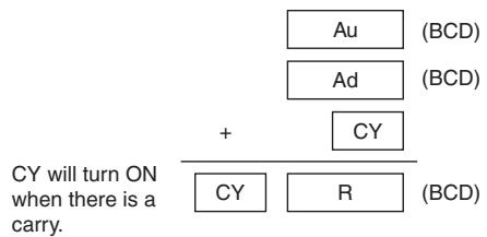
+BCL
+BCL(407) adds the BCD values in Au and Au + 1 , Ad and Ad + 1 , and CY and outputs the result to R, R+1.
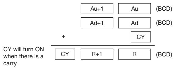
Hint
- To clear the Carry Flay (CY), execute the Clear Carry (CLC(041)) instruction.
Sample program
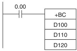
When CIO 0.00 is ON in the following example, D100, D110, and CY will be added as 4-digit BCD values, and the result will be output to D120.
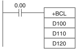
When CIO 0.00 is ON in the following example, D101, D100, D111, D110, and CY will be added as 8-digit BCD values, and the result will be output to D121 and D120.

| Instruction | Mnemonic | Variations | Function code | Function |
| SIGNED BINARY SUBTRACT WITHOUT CARRY | - | @- | 410 | Subtracts 4-digit (single-word) hexadecimal data and/or constants. |
| DOUBLE SIGNED BINARY SUBTRACT WITHOUT CARRY | -L | @-L | 411 | Subtracts 8-digit (double-word) hexadecimal data and/or constants. |
| Symbol | - | -L | ||
| -(-410) | -(-410) | |||
| Mi | Mi: Minuend word | Mi | Mi: Minuend word | |
| Su | Su: Subtrahend word | Su | Su: Subtrahend word | |
| R | R: Result word | R | R: Result word | |
Applicable Program Areas
| Area | Step program areas | Subroutines | Interrupt tasks |
| Usage | OK | OK | OK |
Operands
| Operand | Description | Data type | Size | ||
| - | -L | - | -L | ||
| Mi | :- Minuend word | INT | DINT | 1 | 2 |
| -L: First minuend word | |||||
| Su | :- Subtrahend word | INT | DINT | 1 | 2 |
| -L: First subtrahend word | |||||
| R | :- Result word | INT | DINT | 1 | 2 |
| -L: First result word | |||||
-Operand Specifications
| Area | Word addresses | Indirect DM addresses | Constants | CF | Pulse bits | TR bits | |||||||
| CIO | WR | HR | AR | T | C | DM | @DM | *DM | |||||
| Mi, Su | OK | OK | OK | OK | OK | OK | OK | OK | OK | OK | --- | --- | --- |
| R | --- | ||||||||||||
Flags
| Name | Label | Operation | |
| - | -L | ||
| Error Flag | P_ER | OFF | OFF |
| Equals Flag | P_EQ | ON when the result is 0. OFF in all other cases. | ON when the result is 0. OFF in all other cases. |
| Carry Flag | P_CY | ON when the subtraction results in a borrow. OFF in all other cases. | ON when the subtraction results in a borrow. OFF in all other cases. |
| Overflow Flag | P_OF | ON when the result of subtracting a negative num- ber from a positive number is in the range 8000 to FFFF hex. OFF in all other cases. | ON when the result of subtracting a negative num- ber from a positive number is in the range 8000000 toFFFFFFF hex. OFF in all other cases. |
| Underflow Flag | P_UF | ON when the result of subtracting a negative num- ber from a positive number is in the range 0000 to 7FFF hex. OFF in all other cases. | ON when the result of subtracting a positive num- ber from a negative number is in the range 0000000 to 7FFFFFFF hex. OFF in all other cases. |
| Negative Flag | P_N | ON when the leftmost bit of the result is 1. OFF in all other cases. | ON when the leftmost bit of the result is 1. OFF in all other cases. |
Function

-(400) subtracts the binary values in Su from Mi and outputs the result to R. When the result is negative, it is output to R as a 2's complement.
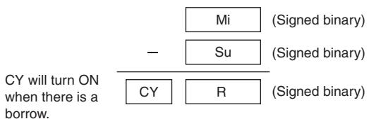

-L(411) subtracts the binary values in Su and Su + 1 from Mi and Mi + 1 and outputs the result to R, R + 1 . When the result is negative, it is output to R and R + 1 as a 2's complement.
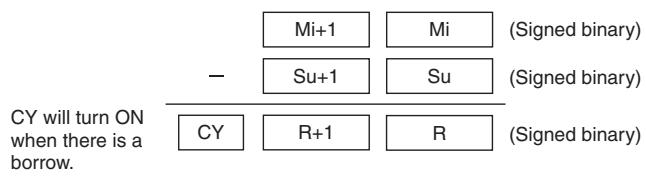
Hint
2's Complement
A 2's complement is the value obtained by subtracting each binary digit from 1 and adding one to the result. For example, the 2's complement for 1101 is calculated as follows: 1111 (F hexadecimal) - 1101 (D hexadecimal) + 1 (1 hexadecimal) = 0011 (3 hexadecimal). The 2's complement for 3039 (hexadecimal) is calculated as follows: FFFF (hexadecimal) - 3039 (hexadecimal) + 0001 (hexadecimal) - CFC7 (hexadecimal). Therefore, in case of 4-digit hexadecimal value, the 2's complement can be calculated as follows: FFFF (hexadecimal) - a (hexadecimal) + 0001 (hexadecimal) = b (hexadecimal). To obtain the true number from the 2's complement b (hexadecimal): a (hexadecimal) = 10000 (hexadecimal) - b (hexadecimal). For example, to obtain the true number from the 2's complement CFC7 (hexadecimal): 10000 (hexadecimal) - CFC7 = 3039.
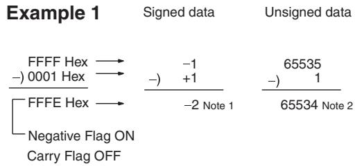
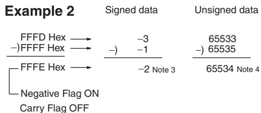
Note 1. Since the Negative Flag is ON, the result (FFFE hex) is a negative value (2's complement) and is thus -2.
2. Since the Carry Flag is OFF, the result (FFFE hex) is an unsigned positive value of 65534.
-
Since the Negative Flag is ON, the result (FFFE hex) is a negative value (2's complement) and is thus -2.
-
Since the Carry Flag is ON, the result (FFFE hex) is a negative value (2's complement) and becomes -2 when converted to a true value.
20F55A10 - B8A360E3 = -97AE06D3. (Hexadecimal)
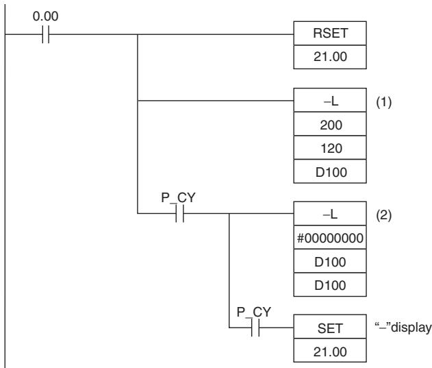
In this example, the eight-digit binary value in CIO 121 and CIO 120 is subtracted from the value in CIO 201 and CIO 200, and the result is output in eight-digit binary to D101 and D100. If the result is negative, the instruction at (2) will be executed, and the actual result will then be output to D101 and D100.
Subtraction at (1)
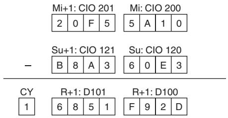
The Carry Flag (CY) is ON, so the result is subtracted from 0000 0000 to obtain the actual number.
Subtraction at (2)
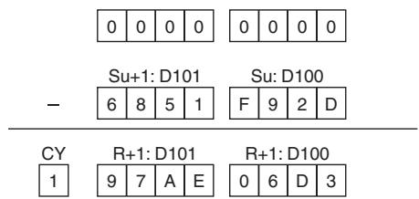
Final Subtraction Result
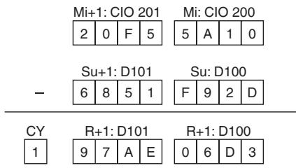
The Carry Flag (CY) is turned ON, so the actual number is -97AE06D3. Because the content of D101 and D100 is negative, CY is used to turn ON CIO 21.00 to indicate this.
Sample program
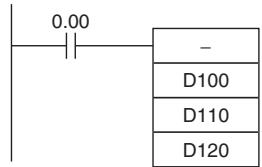
When CIO 0.00 is ON in the following example, D110 will be subtracted from D100 as 4-digit signed binary values and the result will be output to D120.
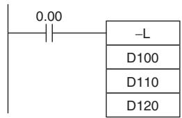
When CIO 0.00 is ON in the following example, D111 and D110 will be subtracted from D101 and D100 as 8-digit signed binary values and the result will be output to D121 and D120.
If the result of the subtraction is a negative number (Mi < Su or Mi+1, Mi < Su+1, Su), the result is output as the 2's complement and the Carry Flag (CY) will turn ON to indicate that the result of the subtraction is negative. To convert the 2's complement to the true number, an instruction which subtracts the result from 0 is necessary using the Carry Flag (CY) as an execution condition.
-C/-CL
| Instruction | Mnemonic | Variations | Function code | Function |
| SIGNED BINARY SUBTRACT WITH CARRY | -C | @-C | 412 | Subtracts 4-digit (single-word) hexadecimal data and/or constants with the Carry Flag (CY). |
| DOUBLE SIGNED BINARY SUBTRACT WITH CARRY | -CL | @-CL | 413 | Subtracts 8-digit (double-word) hexadecimal data and/or constants with the Carry Flag (CY). |
| Symbol | -C | -CL | ||
| —| —| —C(412) —| —| —Mi: Minuend word Su: Subtrahend word R: Result word | —| —| —Mi: Minuend word Su: Subtrahend word R: Result word | —| —| —CL(413) —| —| —Mi: Minuend word Su: Subtrahend word R: Result word | —| —| —Mi: Minuend word Su: Subtrahend word R: Result word | |
Applicable Program Areas
| Area | Step program areas | Subroutines | Interrupt tasks |
| Usage | OK | OK | OK |
Operands
| Operand | Description | Data type | Size | ||
| -C | -CL | -C | -CL | ||
| Mi | -C: Minuend word -CL: First minuend word | INT | DINT | 1 | 2 |
| Su | -C: Subtrahend word -CL: First subtrahend word | INT | DINT | 1 | 2 |
| R | -C: Result word -CL: First result word | INT | DINT | 1 | 2 |
-Operand Specifications
| Area | Word addresses | Indirect DM addresses | Constants | CF | Pulse bits | TR bits | |||||||
| CIO | WR | HR | AR | T | C | DM | @DM | *DM | |||||
| Mi, Su | OK | OK | OK | OK | OK | OK | OK | OK | OK | OK | --- | --- | --- |
| R | --- | ||||||||||||
Flags
| Name | Label | Operation | |
| -C | -CL | ||
| Error Flag | P_ER | OFF | OFF |
| Equals Flag | P_EQ | ON when the subtraction result is 0. OFF in all other cases. | ON when the result is 0. OFF in all other cases. |
| Carry Flag | P_CY | ON when the subtraction results in a borrow. OFF in all other cases. | ON when the results in a borrow. OFF in all other cases. |
| Overflow Flag | P_OF | ON when the result of subtracting a negative num- ber and CY from a positive number is in the range 8000 to FFFF hex. OFF in all other cases. | ON when the result of subtracting a negative num- ber and CY from a positive number is in the range 80000000 to FFFFFFFF hex. OFF in all other cases. |
| Underflow Flag | P_UF | ON when the result of subtracting a positive num- ber and CY from a negative number is in the range 0000 to 7FFF hex. OFF in all other cases. | ON when the result of subtracting a positive num- ber and CY from a negative number is in the range 00000000 to 7FFFFFFF hex. OFF in all other cases. |
| Negative Flag | P_N | ON when the leftmost bit of the result is 1. OFF in all other cases. | ON when the leftmost bit of the result is 1. OFF in all other cases. |
Function
- C
-C(412) subtracts the binary values in Su and CY from Mi, and outputs the result to R. When the result is negative, it is output to R as a 2's complement.
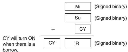
-CL
-CL(413) subtracts the binary values in Su and Su+1 and CY from Mi and Mi+1, and outputs the result to R, R+1. When the result is negative, it is output to R, R+1 as a 2's complement.
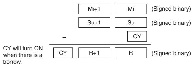
Hint
- To clear the Carry Flag (CY), execute the Clear Carry (CLC(041)) instruction.
2's Complement
A 2's complement is the value obtained by subtracting each binary digit from 1 and adding one to the result.
Example: The 2's complement for the binary number 1101 is as follows: 1111 (F hex) - 1101 (D hex) + 1 (1 hex) = 0011 (3 hex).
Example: The 2's complement for the 4-digit hexadecimal number 3039 is as follows: FFFF hex - 3039 hex + 0001 hex = CFC7 hex.
Accordingly, the 2's complement for the 4-digit hexadecimal value "a" is as follows: FFFF hex - a hex + 0001 hex = b hex.
And to obtain the true number “a” hex from the 2’s complement “b” hex: a hex + 10000 hex - b hex.
Example: To obtain the true number from the 2's complement CFC& hex: 10000 hex - CFC7 hex = 3039 hex.
Sample program
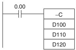
When CIO 0.00 is ON in the following example, D110 and CY will be subtracted from D100 as 4-digit signed binary values and the result will be output to D120.

When CIO 0.00 is ON in the following example, D111, D110 and CY will be subtracted from D101 and D100 as 8-digit signed binary values, and the result will be output to D121 and D120.
If the result of the subtraction is a negative number (Mi < Su or Mi+1, Mi < Su+1, Su), the result is output as a 2's complement. The Carry Flag (CY) will turn ON. To convert the 2's complement to the true number, a program which subtracts the result from 0 is necessary, as an input condition of the Carry Flag (CY). The Carry Flag turning ON thus indicates that the result of the subtraction is negative.
-B/-BL
| Instruction | Mnemonic | Variations | Function code | Function |
| BCD SUBTRACT WITHOUT CARRY | -B | @–B | 414 | Subtracts 4-digit (single-word) BCD data and/or constants. |
| DOUBLE BCD SUBTRACT WITHOUT CARRY | -BL | @–BL | 415 | Subtracts 8-digit (double-word) BCD data and/or constants. |
| Symbol | -B | -BL | ||
| —| —| —B(414) —| —| —Mi: Minuend word Su: Subtrahend word R: Result word | —| —| —BL(415) —| —| —Mi: 1st minuend word Su: 1st subtrahend word R: 1st result word | —| —| —Mi: 1st minuend word Su: 1st subtrahend word R: 1st result word | ||
Applicable Program Areas
| Area | Step program areas | Subroutines | Interrupt tasks |
| Usage | OK | OK | OK |
Operands
| Operand | Description | Data type | Size | ||
| -B | -BL | -B | -BL | ||
| Mi | -B: Minuend word -BL: First minuend word | WORD | DWORD | 1 | 2 |
| Su | -B: Subtrahend word -BL: First subtrahend word | WORD | DWORD | 1 | 2 |
| R | -B: Result word -BL: First result word | WORD | DWORD | 1 | 2 |
- Operand Specifications
| Area | Word addresses | Indirect DM addresses | Constants | CF | Pulse bits | TR bits | |||||||
| CIO | WR | HR | AR | T | C | DM | @DM | *DM | |||||
| Mi, Su | OK | OK | OK | OK | OK | OK | OK | OK | OK | OK | --- | --- | --- |
| R | --- | ||||||||||||
Flags
| Name | Label | Operation | |
| -B | -BL | ||
| Error Flag | P_ER | ·ON when Mi is not BCD. ·ON when Su is not BCD. ·OFF in all other cases. | ·ON when Mi and/or Mi +1 are not BCD. ·ON when Su and/or Su +1 are not BCD. ·OFF in all other cases. |
| Equals Flag | P_EQ | ·ON when the result is 0. ·OFF in all other cases. | ·ON when the result is 0. ·OFF in all other cases. |
| Carry Flag | P_CY | ·ON when the subtraction results in a borrow. ·OFF in all other cases. | ·ON when the subtraction results in a borrow. ·OFF in all other cases. |
Function
- B
-B(414) subtracts the BCD values in Su from Mi and outputs the result to R. If the result of the subtraction is negative, the result is output as a 10's complement.

-
BL
-
BL(415) subtracts the BCD values in Su and Su+1 from Mi and Mi+1 and outputs the result to R, R+1. If the result is negative, it is output to R, R+1 as a 10's complement.
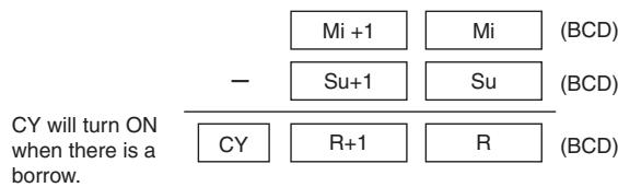
Hint
10's Complement
A 10's complement is the value obtained by subtracting each digit from 9 and adding one to the result. For example, the 10's complement for 7556 is calculated as follows: 9999 - 7556 + 1 = 2444 . For a four digit number, the 10's complement of A is 9999 - A + 1 = B . To obtain the true number from the 10's complement B: A = 10000 - B . For example, to obtain the true number from the 10's complement 2444: 10000 - 2444 = 7556 .
Example: 9,583,960 - 17,072,641 = -7,488,681. (BCD)
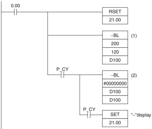
In this example, the eight-digit BCD content of CIO 121 and CIO 120 is subtracted from the content of CIO 201 and CIO 200, and the result is output in eight-digit BCD to D101 and D100. The result is negative, so the instruction at (2) will be executed, and the true value will then be output to D101 and D100.
Subtraction at (1)
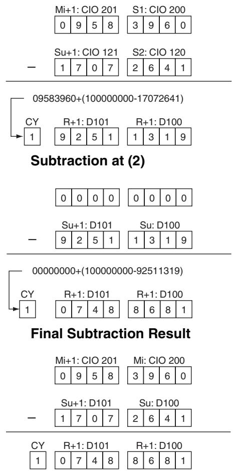
The Carry Flag (CY) is ON, so the result is subtracted from 0000 0000.
The Carry Flag (CY) will be turned ON, so the actual number is -7,488,681. Because the content of D101 and D100 is negative, CY is used to turn ON CIO 21.00 to indicate this.
Sample program
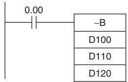
When CIO 0.00 is ON in the following example, D110 is subtracted from D100 as 4-digit BCD values, and the result will be output to D120.
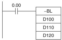
When CIO 0.00 is ON in the following example, D111 and D110 will be subtracted from D101 and D100 as 8-digit BCD values, and the result will be output to D121 and D120.
If the result of the subtraction is a negative number (Mi < Su or Mi +1 , Mi < Su +1 , Su), the result is output as a 10's complement. The Carry Flag (CY) will turn ON. To convert the 10's complement to the true number, a program which subtracts the result from 0 is necessary, as an input condition of the Carry Flag (CY). The Carry Flag turning ON thus indicates that the result of the subtraction is negative.
-BC/-BCL
| Instruction | Mnemonic | Variations | Function code | Function |
| BCD SUBTRACT WITH CARRY | -BC | @-BC | 416 | Subtracts 4-digit (single-word) BCD data and/or constants with the Carry Flag (CY). |
| DOUBLE BCD SUBTRACT WITH CARRY | -BCL | @-BCL | 417 | Subtracts 8-digit (double-word) BCD data and/or constants with the Carry Flag (CY). |
| Symbol | -BC | -BCL | ||
| -BC(416) | Mi: Minuend word Su: Subtrahend word R: Result word | -BC(417) | Mi: 1st minuend word Su: 1st subtrahend word R: 1st result word | |
| Mi | Mi | |||
| Su | Su | |||
| R | R | |||
Applicable Program Areas
| Area | Step program areas | Subroutines | Interrupt tasks |
| Usage | OK | OK | OK |
Operands
| Operand | Description | Data type | Size | ||
| -BC | -BCL | -BC | -BCL | ||
| Mi | -BC: Minuend word -BCL: First minuend word | WORD | DWORD | 1 | 2 |
| Su | -BC: Subtrahend word -BCL: First subtrahend word | WORD | DWORD | 1 | 2 |
| R | -BC: Result word -BCL: First result word | WORD | DWORD | 1 | 2 |
- Operand Specifications
| Area | Word addresses | Indirect DM addresses | Constants | CF | Pulse bits | TR bits | |||||||
| CIO | WR | HR | AR | T | C | DM | @DM | *DM | |||||
| Mi, Su | OK | OK | OK | OK | OK | OK | OK | OK | OK | OK | --- | --- | --- |
| R | --- | ||||||||||||
Flags
| Name | Label | Operation | |
| -BC | -BCL | ||
| Error Flag | P_ER | • ON when Mi is not BCD. • ON when Su is not BCD. • OFF in all other cases. | • ON when Mi and/or Mi +1 are not BCD. • ON when Su and/or Su +1 are not BCD. • OFF in all other cases. |
| Equals Flag | P_EQ | • ON when the result is 0. • OFF in all other cases. | • ON when the result is 0. • OFF in all other cases. |
| Carry Flag | P_CY | • ON when the subtraction results in a borrow. • OFF in all other cases. | • ON when the subtraction results in a borrow. • OFF in all other cases. |
Function
-BC
-BC(416) subtracts BCD values in Su and CY from Mi and outputs the result to R. If the result is negative, it is output to R as a 10's complement.
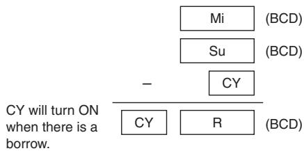
- BCL
-BCL(417)subtracts the BCD values in Su, Su + 1 , and CY from Mi and Mi + 1 and outputs the result to R, R + 1 . If the result is negative, it is output to R, R + 1 as a 10's complement.
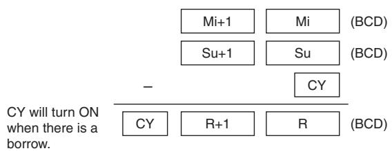
Hint
- To clear the Carry Flay (CY), execute the Clear Carry (CLC(041)) instruction.
10's Complement
A 10's complement is the value obtained by subtracting each digit from 9 and adding one to the result. For example, the 10's complement for 7556 is calculated as follows: 9999 - 7556 + 1 = 2444 . For a four digit number, the 10's complement of A is 9999 - A + 1 = B . To obtain the true number from the 10's complement B: A = 10000 - B . For example, to obtain the true number from the 10's complement 2444: 10000 - 2444 = 7556 .
Sample program
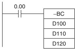
When CIO 0.00 is ON in the following example, D110 and CY will be subtracted from D100 as 4-digit BCD values, and the result will be output to D120.
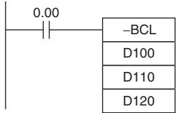
When CIO 0.00 is ON in the following example, D111, D110, and CY will be subtracted from D101 and D100 as 8-digit BCD values, and the result will be output to D121 and D120.
If the result of the subtraction is a negative number (Mi < Su or Mi +1 , Mi < Su +1 , Su), the result is output as a 10's complement. The Carry Flag (CY) will turn ON. To convert the 10's complement to the true number, a program which subtracts the result from 0 is necessary, as an input condition of the Carry Flag (CY). The Carry Flag turning ON thus indicates that the result of the subtraction is negative.

| Instruction | Mnemonic | Variations | Function code | Function |
| SIGNED BINARY MULTIPLY | * | @* | 420 | Multiplies 4-digit signed hexadecimal data and/or constants. |
| DOUBLE SIGNED BINARY MULTIPLY | *L | @@L | 421 | Multiplies 8-digit signed hexadecimal data and/or constants. |
| Symbol | * | *L | ||
| *(420) | Md: Multipicand word | *(421) | Md: 1st multiplicand word | |
| Md | Md | Mr: 1st multiplier word | ||
| Mr | Mr: Multiplier word | Mr | ||
| R | R: Result word | R | R: 1st result word | |
Applicable Program Areas
| Area | Step program areas | Subroutines | Interrupt tasks |
| Usage | OK | OK | OK |
Operands
| Operand | Description | Data type | Size | ||
| * | *L | * | *L | ||
| Md | *: Multipicand word *L: First multiplicand word | INT | DINT | 1 | 2 |
| Mr | *: Multiplier word *L: First multiplier word | INT | DINT | 1 | 2 |
| R | First result word | DINT | LINT | 2 | 4 |
-Operand Specifications
| Area | Word addresses | Indirect DM addresses | Constants | CF | Pulse bits | TR bits | |||||||
| CIO | WR | HR | AR | T | C | DM | @DM | *DM | |||||
| Md, Mr | OK | OK | OK | OK | OK | OK | OK | OK | OK | OK | --- | --- | --- |
| R | --- | ||||||||||||
Flags
| Name | Label | Operation | |
| * | *L | ||
| Error Flag | P_ER | OFF | OFF |
| Equals Flag | P_EQ | ON when the result is 0. OFF in all other cases. | ON when the result is 0. OFF in all other cases. |
| Negative Flag | P_N | ON when the leftmost bit of the result is 1. OFF in all other cases. | ON when the leftmost bit of the result is 1. OFF in all other cases. |
Function

^*(420) multiplies the signed binary values in Md and Mr and outputs the result to R, R + 1
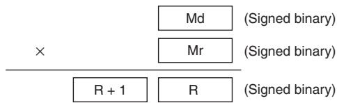
^*L
^*L(421) multiplies the signed binary values in Md and Md + 1 and Mr and Mr + 1 and outputs the result to R, R + 1 , R + 2 , and R + 3 .

Sample program
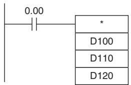
When CIO 0.00 is ON in the following example, D100 and D110 will be multiplied as 4-digit signed hexadecimal values and the result will be output to D120 and D121.
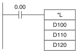
When CIO 0.00 is ON in the following example, D101, D100, D111, and D110 will be multiplied as 8-digit signed hexadecimal values and the result will be output to D123, D122, D121 and D120.
*B/*BL
| Instruction | Mnemonic | Variations | Function code | Function |
| BCD MULTIPLY | *B | @*B | 424 | Multiplies 4-digit (single-word) BCD data and/or constants. |
| DOUBLE BCD MULTIPLY | *BL | @*BL | 425 | Multiplies 8-digit (double-word) BCD data and/or constants. |
| Symbol | *B | *BL | ||
| -B(424) | -Md: Multipicand word | -Md: 1st multiplicand word | Md: 1st multiplicand word | |
| Md | ||||
| Mr | Mr: Multiplier word | Mr: 1st multiplier word | Mr: 1st multiplier word | |
| R | R: Result word | R: 1st result word | R: 1st result word | |
Applicable Program Areas
| Area | Step program areas | Subroutines | Interrupt tasks |
| Usage | OK | OK | OK |
Operands
| Operand | Description | Data type | Size | ||
| *B | *BL | *B | *BL | ||
| Md | *B: Multipicand word *BL: First multiplicand word | WORD | DWORD | 1 | 2 |
| Mr | *B: Multiplier word *BL: First multiplier word | WORD | DWORD | 1 | 2 |
| R | First result word | DWORD | LWORD | 2 | 4 |
-Operand Specifications
| Area | Word addresses | Indirect DM addresses | Constants | CF | Pulse bits | TR bits | |||||||
| CIO | WR | HR | AR | T | C | DM | @DM | *DM | |||||
| Md, Mr | OK | OK | OK | OK | OK | OK | OK | OK | OK | OK | --- | --- | --- |
| R | --- | ||||||||||||
Flags
| Name | Label | Operation | |
| *B | *BL | ||
| Error Flag | P_ER | • ON when Md is not BCD. • ON when Mr is not BCD. • OFF in all other cases. | • ON when Md and/or Md+1 are not BCD. • ON when Mr and/or Mr +1 are not BCD. • OFF in all other cases. |
| Equals Flag | P_EQ | • ON when the result is 0. • OFF in all other cases. | • ON when the result is 0. • OFF in all other cases. |
Function
^*B
*B(424) multiplies the BCD content of Md and Mr and outputs the result to R, R+1.
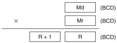
*BL
*BL(425) multiplies BCD values in Md and Md+1 and Mr and Mr+1 and outputs the result to R, R+1, R+2, and R+3.
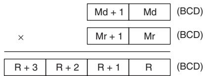
Sample program
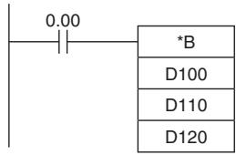
When CIO 0.00 is ON in the following example, D100 and D110 will be multiplied as 4-digit BCD values and the result will be output to D121 and D120.
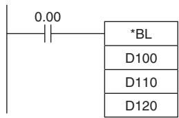
When CIO 0.00 is ON in the following example, D101, D100, D111, and D110 will be multiplied as 8-digit unsigned BCD values and the result will be output to D123, D122, D121 and D120.
1, /L
| Instruction | Mnemonic | Variations | Function code | Function |
| SIGNED BINARY DIVIDE | / | @/ | 430 | Divides 4-digit (single-word) signed hexadecimal data and/or constants. |
| DOUBLE SIGNED BINARY DIVIDE | /L | %@/L | 431 | Divides 8-digit (double-word) signed hexadecimal data and/or constants. |
| Symbol | / | /L | ||
| /(430) | Dd: Dividend word | /(431) | Dd: 1st dividend word | |
| Dd | Dd | Dr: 1st divisor word | ||
| Dr | Dr: Divisor word | Dr | ||
| R | R: Result word | R | R: 1st result word | |
Applicable Program Areas
| Area | Step program areas | Subroutines | Interrupt tasks |
| Usage | OK | OK | OK |
Operands
| Operand | Description | Data type | Size | ||
| / | /L | / | /L | ||
| Dd | : Dividend word /L: First dividend word | INT | DINT | 1 | 2 |
| Dr | : Divisor word /L: First divisor word | INT | DINT | 1 | 2 |
| R | First result word | DWORD | LWORD | 2 | 4 |
- Operand Specifications
| Area | Word addresses | Indirect DM addresses | Constants | CF | Pulse bits | TR bits | |||||||
| CIO | WR | HR | AR | T | C | DM | @DM | *DM | |||||
| Dd, Dr | OK | OK | OK | OK | OK | OK | OK | OK | OK | OK | --- | --- | --- |
| R | --- | ||||||||||||
Flags
| Name | Label | Operation |
| Error Flag | P_ER | ON when the divisor is 0. OFF in all other cases. |
| Equals Flag | P_EQ | ON when as a result of the division, R/R+1, R is 0. OFF in all other cases. |
| Negative Flag | P_N | ON when the leftmost bit of the R/R+1, R is 1. OFF in all other cases. |
Function
/(430) divides the signed binary (16 bit) values in Dd by those in Dr and outputs the result to R, R+1. The quotient is placed in R and the remainder in R+1.
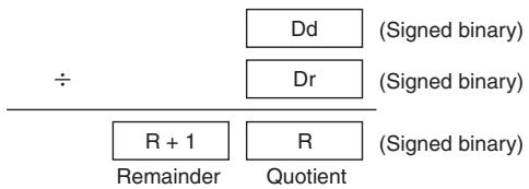
Note Division of hexadecimal #8000 by #FFFF is undefined.
/L(431) divides the signed binary values in Dd and Dd + 1 by those in Dr and Dr + 1 and outputs the result to R, R + 1 , R + 2 , and R + 3 . The quotient is output to R and R + 1 and the remainder is output to R + 2 and R + 3 .
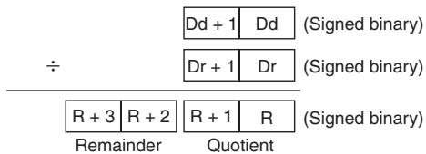
Note Division of hexadecimal #80000000 by FFFFFFFF is undefined.
Sample program
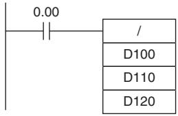
When CIO 0.00 is ON in the following example, D100 will be divided by D110 as 4-digit signed binary values and the quotient will be output to D120 and the remainder to D121.
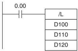
When CIO 0.00 is ON in the following example, D101 and D100 are divided by D111 and D110 as 8-digit signed hexadecimal values and the quotient will be output to D121 and D120 and the remainder to D123 and D122.
/B, /BL
| Instruction | Mnemonic | Variations | Function code | Function |
| BCD DIVIDE | /B | @/B | 434 | Divides 4-digit (single-word) BCD data and/or constants. |
| DOUBLE BCD DIVIDE | /BL | @/BL | 435 | Divides 8-digit (double-word) BCD data and/or constants. |
| Symbol | /B | /BL | ||
| —| |—/B(434) | —| |—/Dd: Dividend word | —| |—/Dd: Dd: 1st dividend word | —| |—/Dr: 1st divisor word | |
| Dr: Divisor word | ||||
| R: Result word | R | R: 1st result word | ||
Applicable Program Areas
| Area | Step program areas | Subroutines | Interrupt tasks |
| Usage | OK | OK | OK |
Operands
| Operand | Description | Data type | Size | ||
| /B | /BL | /B | /BL | ||
| Dd | /B: Dividend word /BL: First dividend word | WORD | DWORD | 1 | 2 |
| Dr | /B: Divisor word /BL: First divisor word | WORD | DWORD | 1 | 2 |
| R | First result word | DWORD | LWORD | 2 | 4 |
-Operand Specifications
| Area | Word addresses | Indirect DM addresses | Constants | CF | Pulse bits | TR bits | |||||||
| CIO | WR | HR | AR | T | C | DM | @DM | *DM | |||||
| Dd, Dr | OK | OK | OK | OK | OK | OK | OK | OK | OK | OK | --- | --- | --- |
| R | --- | ||||||||||||
Flags
| Name | Label | Operation | |
| /B | /BL | ||
| Error Flag | P_ER | • ON when Dd is not BCD. • ON when Dr is not BCD. • ON when the divisor is 0. • OFF in all other cases. | • ON when Dd, Dd+1 is not BCD. • ON when Dr, Dr +1 is not BCD. • ON when the divisor is 0. • OFF in all other cases. |
| Equals Flag | P_EQ | • ON when as a result of the division R is 0. • OFF in all other cases. | • ON when as a result of the division R+1, R is 0. • OFF in all other cases. |
Function
/B
/B(434) divides the BCD content of Dd by those of Dr and outputs the quotient to R and the remainder to R+1.
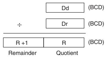
/BL
/BL(435) divides BCD values in Dd and Dd+1 by those in Dr and Dr+1 and outputs the quotient to R, R+1 and the remainder to R+2, R+3.
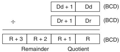
Sample program
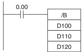
When CIO 0.00 is ON in the following example, D100 will be divided by D110 as 4-digit BCD values and the quotient will be output to D120 and the remainder to D121.
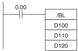
When CIO 0.00 is ON in the following example, D101 and D100 will be divided by D111 and D110 as 8-digit BCD values and the quotient will be output to D121 and D120 and the remainder to D123 and D122.
Conversion Instructions
BIN/BINL
| Instruction | Mnemonic | Variations | Function code | Function |
| BCD TO BINARY | BIN | @BIN | 023 | Converts BCD data to binary data. |
| DOUBLE BCD TO DOUBLE BINARY | BINL | @BINL | 058 | Converts 8-digit BCD data to 8-digit hexadecimal (32-bit binary) data. |
| Symbol | BIN | BINL | ||
| BIN(023)S | S: Source wordR: Result word | BINL(058)S | S: First source wordR: First result word | |
Applicable Program Areas
| Area | Step program areas | Subroutines | Interrupt tasks |
| Usage | OK | OK | OK |
Operands
| Operand | Description | Data type | Size | ||
| BIN | BINL | BIN | BINL | ||
| S | BIN: Source word | ||||
| BINL: First source word | WORD | DWORD | 1 | 2 | |
| R | BIN: Results word | ||||
| BINL: First result word | UINT | UDINT | 1 | 2 | |
- Operand Specifications
| Area | Word addresses | Indirect DM addresses | Constants | CF | Pulse bits | TR bits | |||||||
| CIO | WR | HR | AR | T | C | DM | @DM | *DM | |||||
| S,R | OK | OK | OK | OK | OK | OK | OK | OK | OK | --- | --- | --- | --- |
Flags
| Name | Label | Operation | |
| BIN | BINL | ||
| Error Flag | P_ER | ON if the content of S is not BCDOFF in all other cases. | ON if the contents of S+1, S are not BCDOFF in all other cases. |
| Equals Flag | P_EQ | ON if the result is 0000OFF in all other cases. | ON if the result is 0OFF in all other cases. |
| Negative Flag | P_N | OFF | OFF |
Function
BIN
BIN(023) converts the BCD data in S to binary data and writes the result to R.

The following diagram shows an example BCD-to-binary conversion.

BINL
BINL(058) converts the 8-digit BCD data in S and S+1 to 8-digit hexadecimal (32-bit binary) data and writes the result to R and R+1.
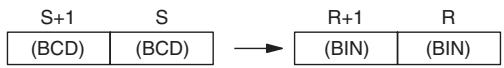
The following diagram shows an example of 8-digit BCD-to-binary conversion.
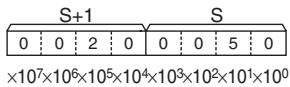
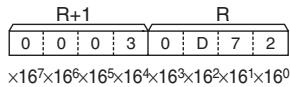
Sample program
When CIO 0.00 is ON in the following example, the 8-digit BCD value in CIO 0010 and CIO 0011 is converted to hexadecimal and stored in D200 and D201.
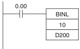
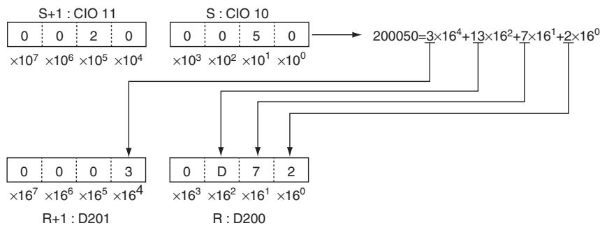
BCD/BCDL
| Instruction | Mnemonic | Variations | Function code | Function |
| BINARY TO BCD | BCD | @BCD | 024 | Converts a word of binary data to a word of BCD data. |
| DOUBLE BINARY TO DOUBLE BCD | BCDL | @BCDL | 059 | Converts 8-digit hexadecimal (32-bit binary) data to 8-digit BCD data. |
| Symbol | BCD | BCDL | ||
| BCD(024)S R | S: Source word D: Result word | BCDL(059)S R | S: First source word D: First result word | |
Applicable Program Areas
| Area | Step program areas | Subroutines | Interrupt tasks |
| Usage | OK | OK | OK |
Operands
| Operand | Description | Data type | Size | ||
| BCD | BCDL | BCD | BCDL | ||
| S | BCD: Source wordBCDL: First source word | UINT | UDINT | 1 | 2 |
| R | BCD: Result wordBCDL: First result word | WORD | DWORD | 1 | 2 |
S: Source Word (BCD)/First Source Word (BCDL)
BCD
S must be between 0000 and 270F hexadecimal (0000 and 9999 decimal).
- BCDL
The content of S+1 and S must be between 0000 0000 and 05F5 E0FF hexadecimal (0000 0000 and 9999 9999 decimal).
- Operand Specifications
| Area | Word addresses | Indirect DM addresses | Constants | CF | Pulse bits | TR bits | |||||||
| CIO | WR | HR | AR | T | C | DM | @DM | *DM | |||||
| S,R | OK | OK | OK | OK | OK | OK | OK | OK | OK | --- | --- | --- | --- |
Flags
| Name | Label | Operation | |
| BCD | BCDL | ||
| Error Flag | P_ER | ON if the content of S exceeds 270F (9999 decimal).OFF in all other cases. | ON if the contents of S and S+1 exceed 05F5E0FF (9999 9999 decimal).OFF in all other cases. |
| Equals Flag | P_EQ | ON if the result is 0000OFF in all other cases. | ON if the result is 0OFF in all other cases. |
Function
BCD
BCD(024) converts the binary data in S to BCD data and writes the result to R.

The following diagram shows an example BCD-to-binary conversion.
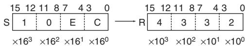
BCDL
BCDL(059) converts the 8-digit hexadecimal (32-bit binary) data in S and S+1 to 8-digit BCD data and writes the result to R and R+1.
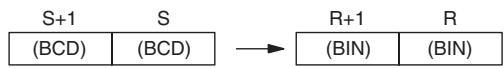
The following diagram shows an example of 8-digit BCD-to-binary conversion.
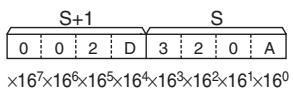
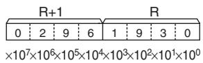
Sample program
When CIO 0.00 is ON in the following example, the hexadecimal value in CIO 11 and CIO 10 is converted to a BCD value and stored in D100 and D101.
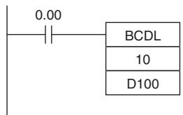
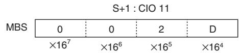
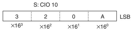
2 × 16^5 + 13 × 16^4 + 3 × 16^3 + 2 × 16^2 + 10 = 2961930
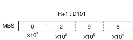
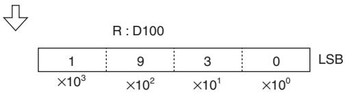
NEG
| Instruction | Mnemonic | Variations | Function code | Function |
| 2'S COMPLEMENT | NEG | @NEG | 160 | Calculates the 2's complement of a word of hexadecimal data. |
| Symbol | NEG | |
| NEG(160) | S: Source word | |
| S | R: Result word | |
Applicable Program Areas
| Area | Step program areas | Subroutines | Interrupt tasks |
| Usage | OK | OK | OK |
Operands
| Operand | Description | Data type | Size |
| S | Source word | WORD | 1 |
| R | Result word | UINT | 1 |
-Operand Specifications
| Area | Word addresses | Indirect DM addresses | Constants | CF | Pulse bits | TR bits | |||||||
| CIO | WR | HR | AR | T | C | DM | @DM | *DM | |||||
| S | OK | OK | OK | OK | OK | OK | OK | OK | OK | OK | --- | --- | --- |
| R | --- | ||||||||||||
Flags
| Name | Label | Operation |
| Error Flag | P_ER | OFF |
| Equals Flag | P_EQ | ON if the result is 0000/0000 0000. OFF in all other cases. |
| Negative Flag | P_N | ON if bit 15 of the result is ON. OFF in all other cases. |
Function
- NEG
NEG(160) calculates the 2's complement of S and writes the result to R. The 2's complement calculation basically reverses the status of the bits in S and adds 1.
2's complement (Complement + 1)
(S) →(R)
Note The result for 8000 hex will be 8000 hex.
Hint
- This operation (reversing the status of the bits and adding 1) is equivalent to subtracting the content of S/S+1 and S from 0000/0000 0000.
Sample program
When CIO 0.00 is ON in the following example, NEG(160) calculates the 2's complement of the content of D100 and writes the result to D200.
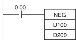
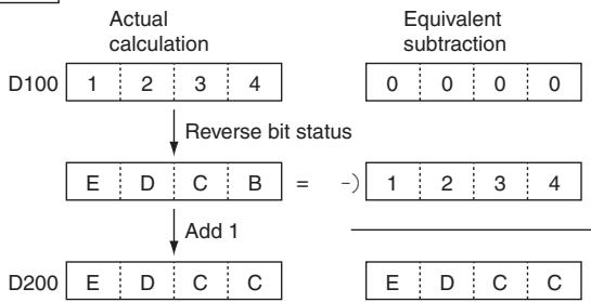
MLPX
| Instruction | Mnemonic | Variations | Function code | Function |
| DATA DECODER | MLPX | @MLPX | 076 | Reads the numerical value in the specified digit (or byte) in the source word with 4-to 16 conversion (or 8-to-256 conversion), turns ON the corresponding bit in the result word, and turns OFF all other bits in the result word. |
| Symbol | MLPX | |
| — | — | |
| MLPX(076) | ||
| S | ||
| C | ||
| R | ||
| S: Source word | ||
| C: Control word | ||
| R: First result word | ||
Applicable Program Areas
| Area | Step program areas | Subroutines | Interrupt tasks |
| Usage | OK | OK | OK |
Operands
| Operand | Description | Data type | Size |
| S | Source word | UINT | 1 |
| C | Control word | UINT | 1 |
| R | First result word | UINT | Variable |
- 4-to-16 bit decoder
S: Source Word
15 12 11 8 7 4 3 0 S Digit 3 Digit 2 Digit 1 Digit 0
Digits from the starting digit going left are decoded
(Returns to digit 3 after digit 0)
R: First Result Word
D: Decoding result of 1st digit of decoded digits
D+1: Decoding result of 2nd digit of decoded digits
D+2: Decoding result of 3rd digit of decoded digits
D+3: Decoding result of 4th digit of decoded digits
Note The result words must be in the same data area.
C: Control Word
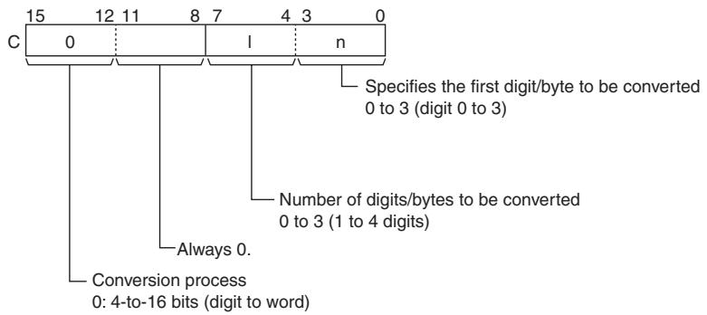
8-to-256 bit conversion
S: Source Word
| 15 | 8 | 7 | 0 |
| Digit 1 | Digit 0 | ||
| Digits from the starting digit going left are decoded (Returns to digit 0 after digit 1) | |||
R: First Result Word
D+15 to D: Decoding result of 1st digit of decoded digits
D+31 to D+16:
Decoding result of 2nd digit of decoded digits
Note The result words must be in the same data area.
C: Control Word
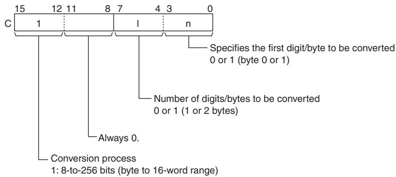
-Operand Specifications
| Area | Word addresses | Indirect DM addresses | Constants | CF | Pulse bits | TR bits | |||||||
| CIO | WR | HR | AR | T | C | DM | @DM | *DM | |||||
| S | OK | OK | OK | OK | OK | OK | OK | OK | OK | --- | --- | --- | --- |
| C | OK | ||||||||||||
| R | --- | ||||||||||||
Flags
| Name | Label | Operation |
| Error Flag | P_ER | ON if C is not within the specified rangesOFF in all other cases. |
Function
MLPX(076) can perform 4-to-16 bit or 8-to-256 bit conversions. Set the leftmost digit of C to 0 to specify 4-to-16 bit conversion and set it to 1 to specify 8-to-256 bit conversion.
- 4-to-16 bit Conversion
When the leftmost digit of C is 0, MLPX(076) takes the value of the specified digit in S (0 to F) and turns ON the corresponding bit in the result word. All other bits in the result word will be turned OFF. Up to four digits can be converted.
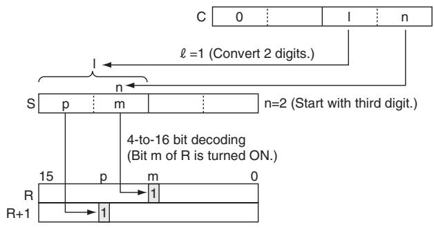
- 8-to-256 bit Conversion
When the leftmost digit of C is 1, MLPX(076) takes the value of the specified byte in S (00 to FF) and turns ON the corresponding bit in the range of 16 result words. All other bits in the result words will be turned OFF. Up to two bytes can be converted.
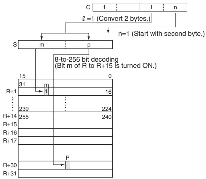
Hint
As shown at right, 4 to 16 decoding consists of taking the 4-bit binary value as the bit number and setting 1 in that bit number and 0 in the other bit numbers of the 16 bits.
As shown at right, 8 to 256 decoding consists of taking the 8-bit binary value as the bit number and setting 1 in that bit number and 0 in the other bit numbers of the 256 bits.
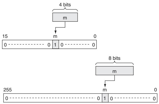
Precaution
- 4-to-16 bit conversion
When two or more digits are being converted, MLPX(076) will read the digits in S from right to left and will wrap around to the rightmost digit after the leftmost digit, if necessary.
- 8-to-256 bit conversion
When two bytes are being converted, MLPX(076) will read the bytes in S from right to left and will wrap around to the rightmost byte if the leftmost byte (byte 1) has been specified as the starting byte.
Sample program
- 4-to-16 bit Conversion
When CIO 0.00 is ON in the following example, MLPX(076) will convert 3 digits in S beginning with digit 1 (the second digit), as indicated by C (#0021). The corresponding bits in D100, D101, and D102 will be turned ON.
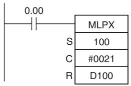
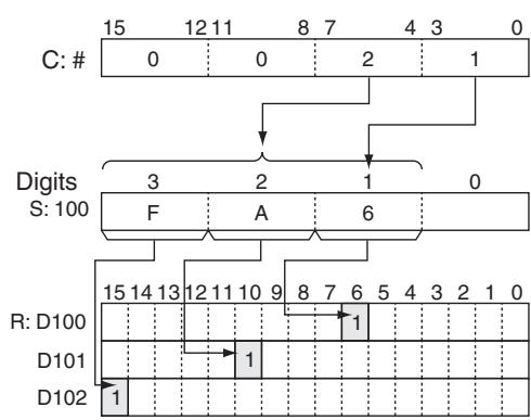
Bits 0 to 3: Starting digit (Digit 1)
Bits 4 to 7: Number of digits (3 digits)
Digit 1 contains 6, so bit 6 is turned ON.
Digit 2 contains A, so bit 10 is turned ON.
Digit 3 contains F, so bit 15 is turned ON.
8-to-256 bit Conversion
When CIO 0.00 is ON in the following example, MLPX(076) will convert the 2 bytes in S beginning with byte 1 (the leftmost byte), as indicated by C (#1011). The corresponding bits in D100 to D115 and D116 to D131 will be turned ON.
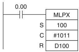
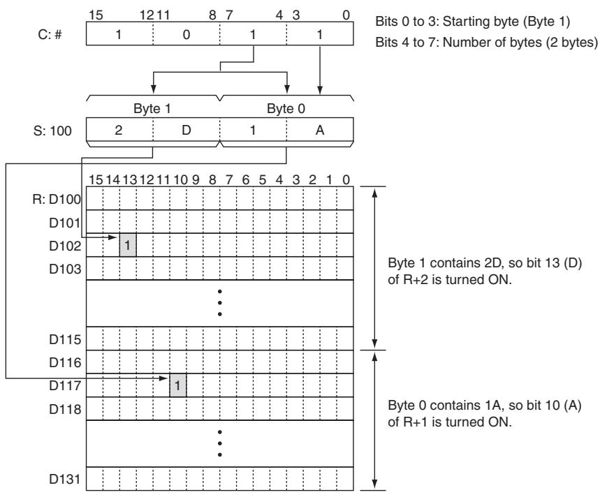
- Example of multi-digit decoding
Example of 4-to-16 bit decoding
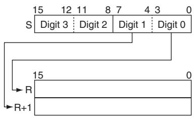
C: #0010
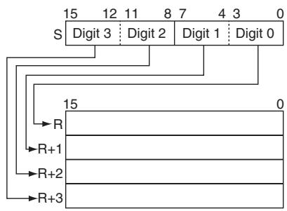
C: #0030
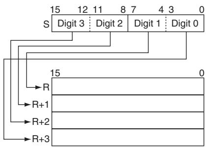
C: #0031
Example of 8-to-256 bit decoding
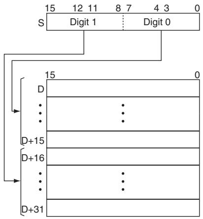
C: #1010

C: #1011
DMPX
| Instruction | Mnemonic | Variations | Function code | Function |
| DATA ENCODER | DMPX | @DMPX | 077 | Find the location of the first or last ON bit within the source word with 16-to-4 conversion (or 256-to-8 conversion), and writes that value to the spec-ified digit (or byte) in the result word. |
| Symbol | DMPX | |
| — | — | DMPX(077) — | |
| S | ||
| R | ||
| C | ||
| C: Control word | ||
Applicable Program Areas
| Area | Step program areas | Subroutines | Interrupt tasks |
| Usage | OK | OK | OK |
Operands
| Operand | Description | Data type | Size |
| S | First source word | UINT | Variable |
| R | Result word | UINT | 1 |
| C | Control word | UINT | 1 |
16-to-4 bit conversion
S: First Source Word
S: 1st digit of digits to be encoded
S+1: 2nd digit of digits to be encoded
S+2: 3rd digit of digits to be encoded
S+3: 4th digit of digits to be encoded
R: Result Word
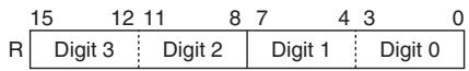
The results of encoding of S to S + 3 are stored from the starting digit going left (returns to digit 0 after digit 3).
Note The source words must be in the same data area.
C: Control Word
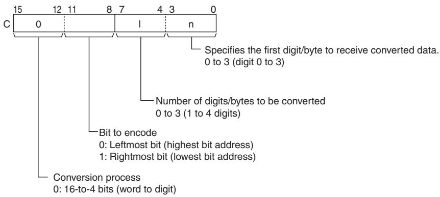
256-to-8 bit conversion
S: First Source Word
S+15 to S: 1st digit of digits to be encoded
S+31 to S+16: 2nd digit of digits to be encoded
R: Result Word
Note The source words must be in the same data area.
C: Control word
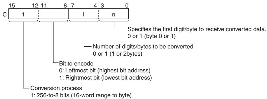
- Operand Specifications
| Area | Word addresses | Indirect DM addresses | Constants | CF | Pulse bits | TR bits | |||||||
| CIO | WR | HR | AR | T | C | DM | @DM | *DM | |||||
| S,R | OK | OK | OK | OK | OK | OK | OK | OK | OK | --- | --- | --- | --- |
| C | OK | ||||||||||||
Flags
| Name | Label | Operation |
| Error Flag | P_ER | ON if any of the source words contains 0000 hex (i.e., no bit to encode).ON if C is not within the specified ranges.OFF in all other cases. |
Function
DMPX(077) can perform 16-to-4 bit or 256-to-8 bit conversions. Set the leftmost digit of C to 0 to specify 16-to-4 bit conversion and set it to 1 to specify 256-to-8 bit conversion.
16-to-4 bit Conversion
When the fourth (leftmost) digit of C is 0, DMPX(077) finds the locations of the leftmost or rightmost ON bits in up to 4 source words and writes these locations to R beginning with the specified digit.
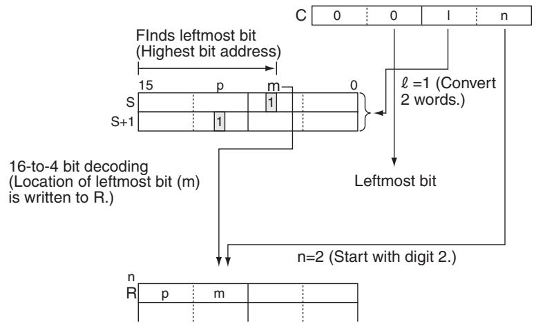
- 256-to-8 bit Conversion
When the fourth (leftmost) digit of C is 1, DMPX(077) finds the locations of the leftmost (highest bit address) or rightmost (lowest bit address) ON bits in one or two 16-word ranges of source words. The locations of these bits are written to R beginning with the specified byte.
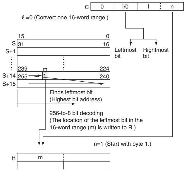
Hint
As shown at right, 16 to 4 encoding consists of converting the bit number (m) of the leftmost or rightmost bit that has 1 set among the 16 bits to a 4-bit binary value.
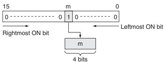
As shown at right, 256 to 8 encoding consists of converting the bit number (m) of the leftmost or rightmost bit that has 1 set among the 256 bits to an 8-bit binary value.
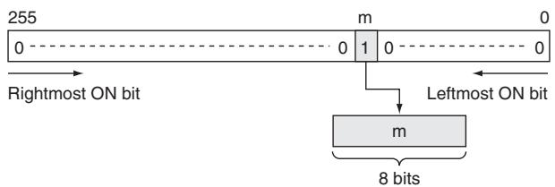
Precaution
16-to-4 bit conversion
When two or more digits are being converted, DMPX(077) will write the values to the digits in R from right to left and will wrap around to the rightmost digit after the leftmost digit, if necessary.
256-to-8 bit conversion
When two bytes are being converted, DMPX(077) will write the values to the bytes in R from right to left and will wrap around to the rightmost byte if the leftmost byte (byte 1) has been specified as the starting byte.
Sample program
16-to-4 bit Conversion
When CIO 0.00 is ON in the following example, DMPX(077) will find the leftmost ON bits in CIO 100, CIO 101, and CIO 102 and write those locations to 3 digits in R beginning with digit 1 (the second digit), as indicated by C (#0021).
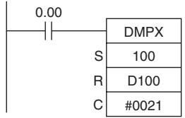

- Example of multi-digit decoding
Example of 16-to-4 bit decoding
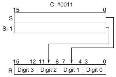
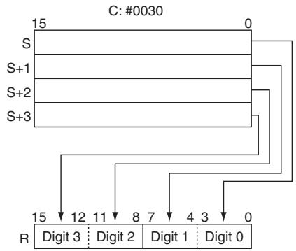
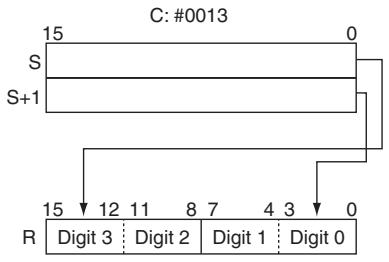
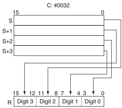
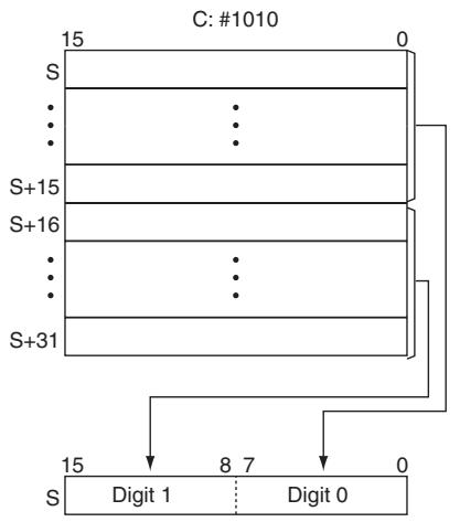
- 256-to-8 bit Conversion
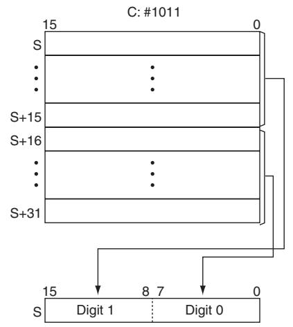
If the conversion data contains 0000 hex, but other data is to be encoded, separate the conversion by using more than one DMPX(077) instructions.
| Instruction | Mnemonic | Variations | Function code | Function |
| ASCII CONVERT | ASC | @ASC | 086 | Converts 4-bit hexadecimal digits in the source word into their 8-bit ASCII equivalents. |
| Symbol | ASC | |
| —|—|— | ASC(086) | |
| S | ||
| DI | ||
| D | ||
| D: Source word | ||
| DI: Digit designator | ||
| D: First destination word | ||
Applicable Program Areas
| Area | Step program areas | Subroutines | Interrupt tasks |
| Usage | OK | OK | OK |
Operands
| Operand | Description | Data type | Size |
| S | Source word | UINT | 1 |
| DI | Digit designator | UINT | 1 |
| D | First destination word | UINT | Variable |
S: Source Word
| 15 | 12 | 11 | 8 | 7 | 4 | 3 | 0 |
| Digit 3 | Digit 2 | Digit 1 | Digit 0 | ||||
Digits from the starting digit of conversion going left are treated as HEX data and converted to ASCII code (returns to digit 0 after digit 3)
D: First Destination Word
| 15 | 8 | 7 | 0 |
| D+1 | Leftmost byte | Rightmost byte | |
| Leftmost byte | Rightmost byte | ||
| D+2 | Leftmost byte | Rightmost byte |
ASCII code is stored in the left word side. The code is stored from the output starting byte of D in the order rightmost byte, leftmost byte.
Note The destination words must be in the same data area.
DI: Digit Designator
The digit designator specifies various parameters for the conversion, as shown in the following diagram.
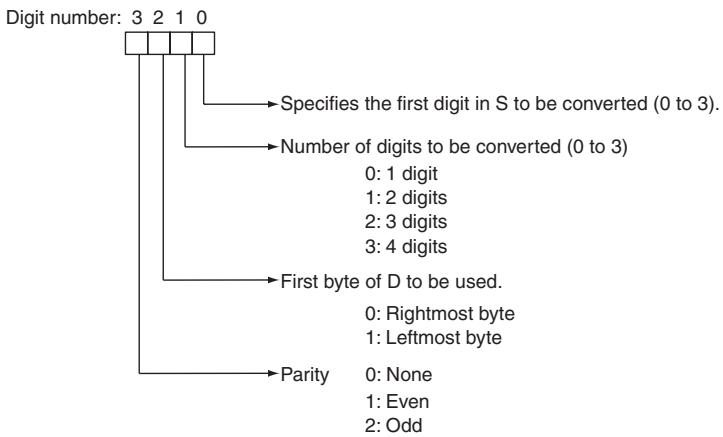
- Operand Specifications
| Area | Word addresses | Indirect DM addresses | Constants | CF | Pulse bits | TR bits | |||||||
| CIO | WR | HR | AR | T | C | DM | @DM | *DM | |||||
| S | OK | OK | OK | OK | OK | OK | OK | OK | OK | --- | --- | --- | --- |
| DI | OK | ||||||||||||
| D | --- | ||||||||||||
Flags
| Name | Label | Operation |
| Error Flag | P_ER | ON if the content of Di is not within the specified ranges. OFF in all other cases. |
Function
ASC(086) treats the contents of S as 4 hexadecimal digits, converts the designated digit(s) of S into their 8-bit ASCII equivalents, and writes this data into the destination word(s) beginning with the specified byte in D.
A parity specification (bits 12 to 15 of K) is possible in the leftmost bit of the ASCII code data, and this can be converted to an odd or even parity bit (the number of bits that are 1 of the eight bits is adjusted to odd or even).
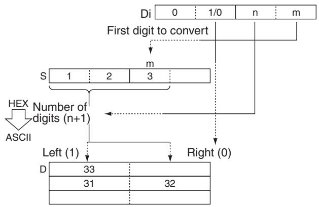
Hint
- The parity bit is appended to the data to enable detection of errors when the data is transmitted. By adding this bit, the number of bits that are 1 in the data can be indicated as odd or even, and if the number of 1s in the received data is not similarly odd or even, it is assumed that an error has occurred.
Precaution
- When multiple digits are specified in the number of digits to be converted (K), the digits are converted in order from the starting conversion digit going left (returns to digit 0 after digit 3), and the conversion results are stored in order from the output position of D going to the left word side (in units of 8 bits).
- Among the data in the conversion result output word, data in positions that are not to be output are held.
- When converting multiple digits, take care that D+1 and D+2CH do not exceed the area.
Sample program
When CIO 0.00 is ON in the following example, ASC(086) converts three hexadecimal digits in D100 (beginning with digit 1) into their ASCII equivalents and writes this data to D200 and D201 beginning with the leftmost byte in D200. In this case, a digit designator of #0121 specifies no parity, the starting byte (when writing) = leftmost byte, the number of digits to read = 3, and the starting digit (when reading) = digit 1.
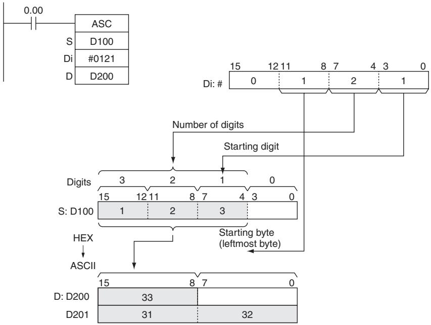
- Example of ASCII code conversion
| Content of conversion data digits | Conversion output data | ||||||||||||
| Value | Bit content | Code | (MSB) bit content (LSB) | ||||||||||
| 0 | 0 | 0 | 0 | 0 | #30 | * | 0 | 1 | 1 | 0 | 0 | 0 | 0 |
| 1 | 0 | 0 | 0 | 1 | #31 | * | 0 | 1 | 1 | 0 | 0 | 0 | 1 |
| 2 | 0 | 0 | 1 | 0 | #32 | * | 0 | 1 | 1 | 0 | 0 | 1 | 0 |
| 3 | 0 | 0 | 1 | 1 | #33 | * | 0 | 1 | 1 | 0 | 0 | 1 | 1 |
| 4 | 0 | 1 | 0 | 0 | #34 | * | 0 | 1 | 1 | 0 | 1 | 0 | 0 |
| 5 | 0 | 1 | 0 | 1 | #35 | * | 0 | 1 | 1 | 0 | 1 | 0 | 1 |
| 6 | 0 | 1 | 1 | 0 | #36 | * | 0 | 1 | 1 | 0 | 1 | 1 | 0 |
| 7 | 0 | 1 | 1 | 1 | #37 | * | 0 | 1 | 1 | 0 | 1 | 1 | 1 |
| 8 | 1 | 0 | 0 | 0 | #38 | * | 0 | 1 | 1 | 1 | 0 | 0 | 0 |
| 9 | 1 | 0 | 0 | 1 | #39 | * | 0 | 1 | 1 | 1 | 0 | 0 | 1 |
| A | 1 | 0 | 1 | 0 | #41 | * | 1 | 0 | 0 | 0 | 0 | 0 | 1 |
| B | 1 | 0 | 1 | 1 | #42 | * | 1 | 0 | 0 | 0 | 0 | 1 | 0 |
| C | 1 | 1 | 0 | 0 | #43 | * | 1 | 0 | 0 | 0 | 0 | 1 | 1 |
| D | 1 | 1 | 0 | 1 | #44 | * | 1 | 0 | 0 | 0 | 1 | 0 | 0 |
| E | 1 | 1 | 1 | 0 | #45 | * | 1 | 0 | 0 | 0 | 1 | 0 | 1 |
| F | 1 | 1 | 1 | 1 | #46 | * | 1 | 0 | 0 | 0 | 1 | 1 | 0 |
- Parity bit - changes according to the parity specification.
- Parity
It is possible to specify the parity of the ASCII data for use in error control during data transmissions. The leftmost bit of each ASCII character will be automatically adjusted for even, odd, or no parity.
- When no parity (0) is designated, the leftmost bit will always be zero. When even parity (1) is designated, the leftmost bit will be adjusted so that the total number of ON bits is even. When odd parity (2) is designated, the leftmost bit of each ASCII character will be adjusted so that there is an odd number of ON bits. The status of the parity bit does not affect the meaning of the ASCII code.
Examples of even parity:
When adjusted for even parity, ASCII "31" (00110001) will be "B1" (10110001: parity bit turned ON to create an even number of ON bits); ASCII "36" (00110110) will be "36" (00110110: parity bit remains OFF because the number of ON bits is already even).
Examples of odd parity:
When adjusted for odd parity, ASCII "36" (00110110) will be "B6" (10110110: parity bit turned ON to create an odd number of ON bits); ASCII "46" (01000110) will be "46" (01000110: parity bit remains OFF because the number of ON bits is already odd).
Examples of Di
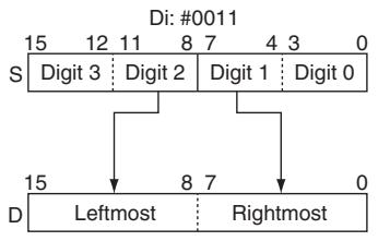
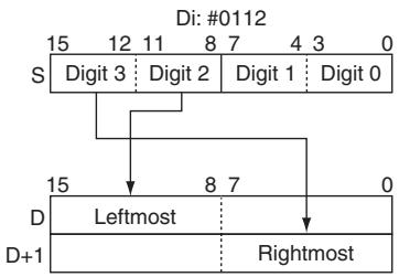
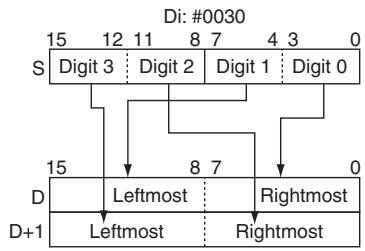
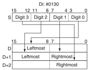
HEX
| Instruction | Mnemonic | Variations | Function code | Function |
| ASCII TO HEX | HEX | @HEX | 162 | Converts up to 4 bytes of ASCII data in the source word to their hexadecimal equivalents and writes these digits in the specified destination word. |
| Symbol | HEX |
| HEX(162) | |
| S | |
| DI | |
| D |
Applicable Program Areas
| Area | Step program areas | Subroutines | Interrupt tasks |
| Usage | OK | OK | OK |
Operands
| Operand | Description | Data type | Size |
| S | First source word | UINT | Variable |
| DI | Digit designator | UINT | 1 |
| D | Destination word | UINT | 1 |
S: First Source Word
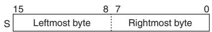
The conversion start byte and bytes to the left are treated as ASCII code and converted to hex (returns to the rightmost byte after the leftmost byte.
D: Destination Word
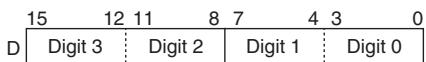
The results of conversion to hex are stored from the starting digit going left (returns to digit 0 after digit 3)
DI: Digit Designator
The digit designator specifies various parameters for the conversion, as shown in the following diagram.
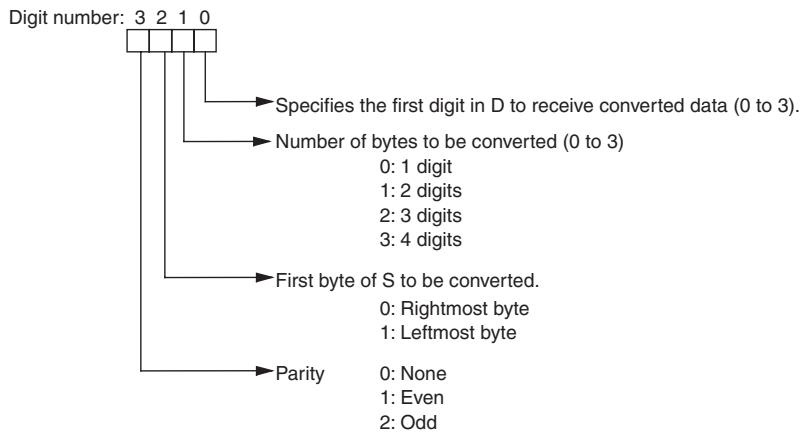
- Operand Specifications
| Area | Word addresses | Indirect DM addresses | Constants | CF | Pulse bits | TR bits | |||||||
| CIO | WR | HR | AR | T | C | DM | @DM | *DM | |||||
| S | OK | OK | OK | OK | OK | OK | OK | OK | OK | --- | --- | --- | --- |
| DI | OK | ||||||||||||
| D | --- | ||||||||||||
Flags
| Name | Label | Operation |
| Error Flag | P_ER | ON if there is a parity error in the ASCII data.ON if the ASCII data in the source words is not equivalent to hexadecimal digitsON if the content of Di is not within the specified ranges.OFF in all other cases. |
Function
HEX(162) treats the contents of the source word(s) as ASCII data representing hexadecimal digits (0 to 9 and A to F), converts the specified number of bytes to hexadecimal, and writes the hexadecimal data to the destination word beginning at the specified digit.
When converting data, the leftmost bit of the ASCII code data can be treated as an odd or even parity bit according to the parity specification.
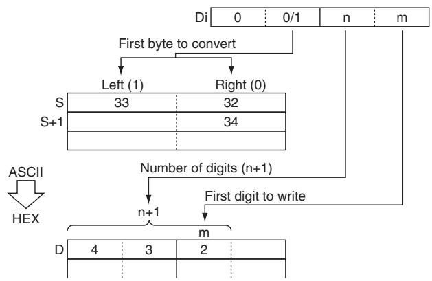
Hint
- The parity bit is appended to the data to enable detection of errors when the data is transmitted. By adding this bit, the number of bits that are 1 in the data can be indicated as odd or even, and if the number of 1s in the received data is not similarly odd or even, it is assumed that an error has occurred.
Precaution
- When multiple digits are specified in the number of digits to be converted (C), the digits are converted in order from the starting conversion position (C) of S going to the left word side, and the conversion results are stored in order from the output starting bit (C) of D going to the left (returns to digit 0 after digit 3).
- Among the data in the conversion result output word, data of bits that are not to be output are held (kept the same as before).
- The following table shows ASCII data which can be contained in the source word(s) (excluding parity bits) and corresponding hexadecimal digits.
| ASCII data (2 hexadecimal digits) | Hexadecimal digits |
| 30 to 39 | 0 to 9 |
| 41 to 46 | A to F |
Sample program
When CIO 0.00 is ON in the following example, HEX(162) converts the ASCII data in D100 and D101 according to the settings of the digit designator. (Di=#0121 specifies no parity, the starting byte (when reading) = leftmost byte, the number of bytes to read = 3, and the starting digit (when writing) = digit 1.) HEX(162) converts three bytes of ASCII data (3 characters) beginning with the leftmost byte of D100 into their hexadecimal equivalents and writes this data to D200 beginning with digit 1.
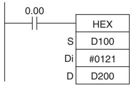
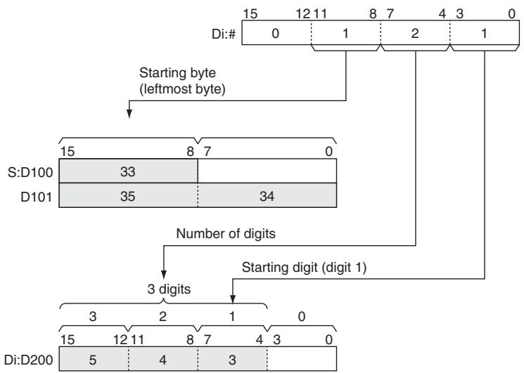
- Parity
It is possible to specify the parity of the ASCII data for use in error control during data transmissions. The leftmost bit in each byte is the parity bit. With no parity the parity bit should always be zero, with even parity the status of the parity bit should result in an even number of ON bits, and with odd parity the status of the parity bit should result in an odd number of ON bits.
The following table shows the operation of HEX(162) for each parity setting.
| Parity setting(leftmost digit of Di) | Operation of HEX(162) |
| No parity (0) | HEX(162) will be executed only when the parity bit in each byte is 0. An error will occur if a parity bit is non-zero. |
| Even parity (1) | HEX(162) will be executed only when there is an even number of ON bits in each byte. An error will occur if a byte has an odd number of ON bits. |
| Odd parity (2) | HEX(162) will be executed only when there is an odd number of ON bits in each byte. An error will occur if a byte has an even number of ON bits. |
- Output example
| Conversion data | Output result (hex data) | ||||||||||||
| ASCII code | (MSB) bit content (LSB) | Value | Bit content | ||||||||||
| #30 | * | 0 | 1 | 1 | 0 | 0 | 0 | 0 | 0 | 0 | 0 | 0 | 0 |
| #31 | * | 0 | 1 | 1 | 0 | 0 | 0 | 1 | 1 | 0 | 0 | 0 | 1 |
| #32 | * | 0 | 1 | 1 | 0 | 0 | 1 | 0 | 2 | 0 | 0 | 1 | 0 |
| #33 | * | 0 | 1 | 1 | 0 | 0 | 1 | 1 | 3 | 0 | 0 | 1 | 1 |
| #34 | * | 0 | 1 | 1 | 0 | 1 | 0 | 0 | 4 | 0 | 1 | 0 | 0 |
| #35 | * | 0 | 1 | 1 | 0 | 1 | 0 | 1 | 5 | 0 | 1 | 0 | 1 |
| #36 | * | 0 | 1 | 1 | 0 | 1 | 1 | 0 | 6 | 0 | 1 | 1 | 0 |
| #37 | * | 0 | 1 | 1 | 0 | 1 | 1 | 1 | 7 | 0 | 1 | 1 | 1 |
| #38 | * | 0 | 1 | 1 | 1 | 0 | 0 | 0 | 8 | 1 | 0 | 0 | 0 |
| #39 | * | 0 | 1 | 1 | 1 | 0 | 0 | 1 | 9 | 1 | 0 | 0 | 1 |
| #41 | * | 1 | 0 | 0 | 0 | 0 | 0 | 1 | A | 1 | 0 | 1 | 0 |
| #42 | * | 1 | 0 | 0 | 0 | 0 | 1 | 0 | B | 1 | 0 | 1 | 1 |
| #43 | * | 1 | 0 | 0 | 0 | 0 | 1 | 1 | C | 1 | 1 | 0 | 0 |
| #44 | * | 1 | 0 | 0 | 0 | 1 | 0 | 0 | D | 1 | 1 | 0 | 1 |
| #45 | * | 1 | 0 | 0 | 0 | 1 | 0 | 1 | E | 1 | 1 | 1 | 0 |
| #46 | * | 1 | 0 | 0 | 0 | 1 | 1 | 0 | F | 1 | 1 | 1 | 1 |
- Parity bit - changes according to the parity specification.
When CIO 0.00 is ON in the following example, HEX(162) converts the ASCII data in D10 beginning with the rightmost byte and writes the hexadecimal equivalents in D300 beginning with digit 1.
The digit designator setting of #1011 specifies even parity, the starting byte (when reading) = rightmost byte, the number of bytes to read = 2, and the starting digit (when writing) = digit 1.)
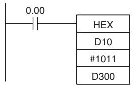
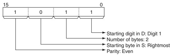
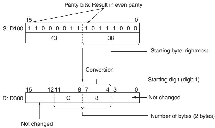
- Example of converting multiple bytes of ASCII code to hex
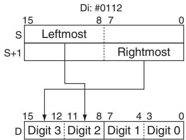
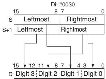
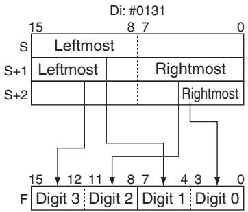
Logic Instructions
ANDW/ANDL
| Instruction | Mnemonic | Variations | Function code | Function |
| LOGICAL AND | ANDW | @ANDW | 034 | Takes the logical AND of corresponding bits in single words of word data and/or constants. |
| DOUBLE LOGICAL AND | ANDL | @ANDL | 610 | Takes the logical AND of corresponding bits in double words of word data and/or constants. |
| Symbol | ANDW | ANDL | ||
| ANDW(034) | I1: Input 1 | ANDL(610) | I1: Input 1 | |
| I1 | I2: Input 2 | I2 | I2: Input 2 | |
| R | R: Result word | R | R: Result word | |
Applicable Program Areas
| Area | Step program areas | Subroutines | Interrupt tasks |
| Usage | OK | OK | OK |
Operands
| Operand | Description | Data type | Size | ||
| ANDW | ANDL | ANDW | ANDL | ||
| I1 | Input 1 | WORD | DWORD | 1 | 2 |
| I2 | Input 2 | WORD | DWORD | 1 | 2 |
| R | Result word | WORD | DWORD | 1 | 2 |
- Operand Specifications
| Area | Word addresses | Indirect DM addresses | Constants | CF | Pulse bits | TR bits | |||||||
| CIO | WR | HR | AR | T | C | DM | @DM | *DM | |||||
| I1, I2 | OK | OK | OK | OK | OK | OK | OK | OK | OK | OK | --- | --- | --- |
| R | --- | ||||||||||||
Flags
| Name | Label | Operation |
| Error Flag | P_ER | OFF |
| Equals Flag | P_EQ | ON when the result is 0. OFF in all other cases. |
| Negative Flag | P_N | ON when the leftmost bit of R is 1. OFF in all other cases. |
Function
ANDW
ANDW(034) takes the logical AND of data specified in I_1 and I_2 and outputs the result to R .
$$ \mathbf {I} _ {1}, \mathbf {I} _ {2} \rightarrow \mathsf {R} $$
| I1 | I2 | R |
| 1 | 1 | 1 |
| 1 | 0 | 0 |
| 0 | 1 | 0 |
| 0 | 0 | 0 |
- ANDL
ANDL(610) takes the logical AND of data specified in I_1 , I_1 + 1 and I_2 , I_2 + 1 and outputs the result to R , R + 1 .
$$ \left(\mathrm {I} _ {1}, \mathrm {I} _ {1} + 1\right) \cdot \left(\mathrm {I} _ {2}, \mathrm {I} _ {2} + 1\right)\rightarrow (\mathrm {R}, \mathrm {R} + 1) $$
| I1, I1+1 | I2, I2+1 | R, R+1 |
| 1 | 1 | 1 |
| 1 | 0 | 0 |
| 0 | 1 | 0 |
| 0 | 0 | 0 |
Sample program
When the execution condition CIO 0.00 is ON, the logical AND is taken of corresponding bits in CIO 11, CIO 10 and CIO 21, CIO 20 and the results will be output to corresponding bits in D201 and D200.
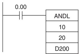
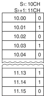
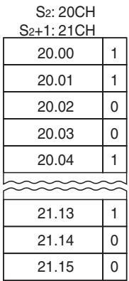
A
C
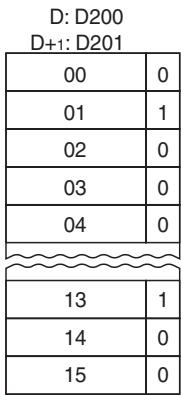
Note The vertical arrow indicates logical AND.
ORW/ORWL
| Instruction | Mnemonic | Variations | Function code | Function |
| LOGICAL OR | ORW | @ORW | 035 | Takes the logical OR of corresponding bits in single words of word data and/or constants. |
| DOUBLE LOGICAL OR | ORWL | @ORWL | 611 | Takes the logical OR of corresponding bits in double words of word data and/or constants. |
| Symbol | ORW | ORWL | ||
| ORW(035) | I1: Input 1 | ORWL(611) | I1: Input 1 | |
| I1 | I2: Input 2 | I1 | I2: Input 2 | |
| R | R: Result word | R | R: Result word | |
Applicable Program Areas
| Area | Step program areas | Subroutines | Interrupt tasks |
| Usage | OK | OK | OK |
Operands
| Operand | Description | Data type | Size | ||
| ORW | ORWL | ORW | ORWL | ||
| I1 | Input 1 | WORD | DWORD | 1 | 2 |
| I2 | Input 2 | WORD | DWORD | 1 | 2 |
| R | Result word | WORD | DWORD | 1 | 2 |
-Operand Specifications
| Area | Word addresses | Indirect DM addresses | Constants | CF | Pulse bits | TR bits | |||||||
| CIO | WR | HR | AR | T | C | DM | @DM | *DM | |||||
| I1, I2 | OK | OK | OK | OK | OK | OK | OK | OK | OK | OK | --- | --- | --- |
| R | --- | ||||||||||||
Flags
| Name | Label | Operation |
| Error Flag | P_ER | OFF |
| Equals Flag | P_EQ | ON when the result is 0. OFF in all other cases. |
| Negative Flag | P_N | ON when the leftmost bit of R is 1. OFF in all other cases. |
Function
ORW
ORW(035) takes the logical OR of data specified in I_1 and I_2 and outputs the result to R.
$$ \mathbf {I} _ {1}, \mathbf {I} _ {2} \rightarrow \mathsf {R} $$
| I1 | I2 | R |
| 1 | 1 | 1 |
| 1 | 0 | 1 |
| 0 | 1 | 1 |
| 0 | 0 | 0 |
ORWL
ORWL(611) takes the logical OR of data specified in I_1 and I_2 as double-word data and outputs the result to R , R + 1 .
$$ (I _ {1}, I _ {1} + 1) + (I _ {2}, I _ {2} + 1) \rightarrow (R, R + 1) $$
| \( I_1, I_1+1 \) | \( I_2, I_2+1 \) | R, R+1 |
| 1 | 1 | 1 |
| 1 | 0 | 1 |
| 0 | 1 | 1 |
| 0 | 0 | 0 |
Sample program
When the execution condition CIO 0.00 is ON, the logical OR is taken of corresponding bits in CIO 21, CIO 20 and CIO 31, CIO 30 and the results will be output to corresponding bits in D501 and D500.
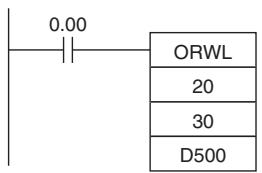
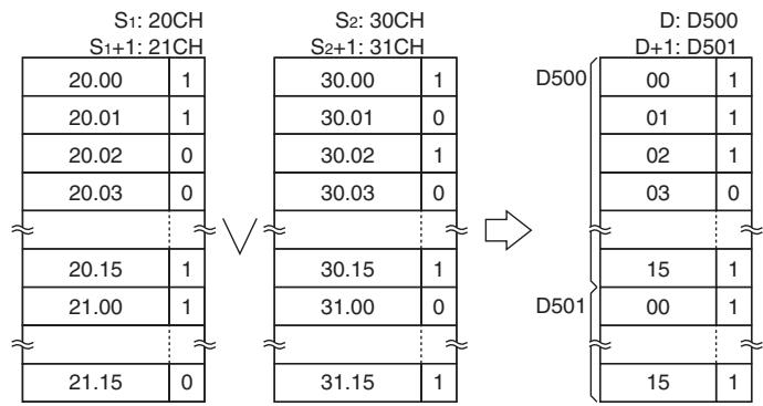
Note The vertical arrow indicates logical OR.
XORW/XORL
| Instruction | Mnemonic | Variations | Function code | Function |
| EXCLUSIVE OR | XORW | @XORW | 036 | Takes the logical exclusive OR of corresponding bits in single words of word data and/or constants. |
| DOUBLE EXCLUSIVE OR | XORL | @XORL | 612 | Takes the logical exclusive OR of corresponding bits in double words of word data and/or constants. |
| Symbol | XORW | XORL | ||
| XORW(036) | I1: Input 1 | XORL(612) | I1: Input 1 | |
| I1 | I2: Input 2 | I1 | I2: Input 2 | |
| R | R: Result word | R | R: Result word | |
Applicable Program Areas
| Area | Step program areas | Subroutines | Interrupt tasks |
| Usage | OK | OK | OK |
Operands
| Operand | Description | Data type | Size | ||
| XORW | XORL | XORW | XORL | ||
| I1 | Input 1 | WORD | DWORD | 1 | 2 |
| I2 | Input 2 | WORD | DWORD | 1 | 2 |
| R | Result word | WORD | DWORD | 1 | 2 |
- Operand Specifications
| Area | Word addresses | Indirect DM addresses | Constants | CF | Pulse bits | TR bits | |||||||
| CIO | WR | HR | AR | T | C | DM | @DM | *DM | |||||
| I1, I2 | OK | OK | OK | OK | OK | OK | OK | OK | OK | OK | --- | --- | --- |
| R | --- | ||||||||||||
Flags
| Name | Label | Operation |
| Error Flag | P_ER | OFF |
| Equals Flag | P_EQ | ON when the result is 0. OFF in all other cases. |
| Negative Flag | P_N | ON when the leftmost bit of R is 1. OFF in all other cases. |
Function
XORW
XORW(036) takes the logical exclusive OR of data specified in I_1 and I_2 and outputs the result to R .
$$ \mathrm {I} _ {1} \bullet \overline {{\mathrm {I} _ {2}}} + \overline {{\mathrm {I} _ {1}}} \bullet \mathrm {I} _ {2} \rightarrow \mathrm {R} $$
| I1 | I2 | R |
| 1 | 1 | 0 |
| 1 | 0 | 1 |
| 0 | 1 | 1 |
| 0 | 0 | 0 |
XORL
XORL(612) takes the logical exclusive OR of data specified in I_1 and I_2 as double-word data and outputs the result to R , R + 1 .
$$ \left(\mathrm {I} _ {1}, \mathrm {I} _ {1} + 1\right) \bullet \overline {{\left(\mathrm {I} _ {2} , \mathrm {I} _ {2} + 1\right)}} + \overline {{\left(\mathrm {I} _ {1} , \mathrm {I} _ {1} + 1\right)}} \bullet \left(\mathrm {I} _ {2}, \mathrm {I} _ {2} + 1\right)\rightarrow (\mathrm {R}, \mathrm {R} + 1) $$
| I1, I1+1 | I2, I2+1 | R, R+1 |
| 1 | 1 | 0 |
| 1 | 0 | 1 |
| 0 | 1 | 1 |
| 0 | 0 | 0 |
Sample program
When the execution condition CIO 0.00 is ON, the logical exclusive OR is taken of corresponding bits in CIO 151, CIO 150 and D1001, D1000 and the results will be output to corresponding bits in D1201 and D1200.
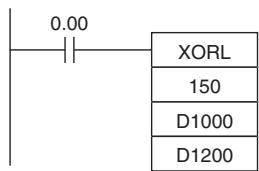
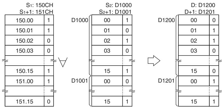
Note The symbol indicates exclusive logical OR.
COM/COML
| Instruction | Mnemonic | Variations | Function code | Function |
| COMPLEMENT | COM | @COM | 029 | Turns OFF all ON bits and turns ON all OFF bits in Wd. |
| DOUBLE COMPLEMENT | COML | @COML | 614 | Turns OFF all ON bits and turns ON all OFF bits in Wd and Wd+1. |
| Symbol | COM | COML | ||
| COM(029) Wd | Wd: Word | COML(614) Wd | Wd: Word | |
Applicable Program Areas
| Area | Step program areas | Subroutines | Interrupt tasks |
| Usage | OK | OK | OK |
Operands
| Operand | Description | Data type | Size | ||
| COM | COML | COM | COML | ||
| Wd | Word | WORD | DWORD | 1 | 2 |
-Operand Specifications
| Area | Word addresses | Indirect DM addresses | Constants | CF | Pulse bits | TR bits | |||||||
| CIO | WR | HR | AR | T | C | DM | @DM | *DM | |||||
| Wd | OK | OK | OK | OK | OK | OK | OK | OK | OK | --- | --- | --- | --- |
Flags
| Name | Label | Operation |
| Error Flag | P_ER | OFF |
| Equals Flag | P_EQ | ON when the result is 0. OFF in all other cases. |
| Negative Flag | P_N | ON when the leftmost bit of R is 1. OFF in all other cases. |
Function
COM
COM(029) reverses the status of every specified bit in Wd.
Wd .. 1 0 and 0 1
Note When using the COM instruction, be aware that the status of each bit will change each cycle in which the execution condition is ON.
COML
COML(614) reverses the status of every specified bit in Wd and Wd+1.
Note When using the COML instruction, be aware that the status of each bit will change each cycle in which the execution condition is ON.
Sample program
When CIO 0.00 is ON in the following example, the status of each bit D100 will be reversed.

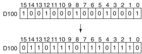
When CIO 0.00 is ON in the following example, the status of each bit in D100 and D101 will be reversed.
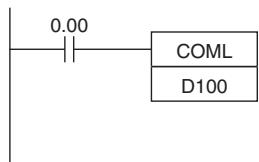
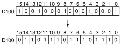
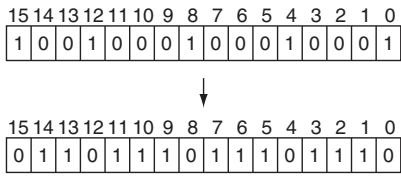
Special Math Instructions
APR
| Instruction | Mnemonic | Variations | Function code | Function |
| ARITHMETIC PROCESS | APR | @APR | 069 | Calculates the sine, cosine, or a linear extrapolation of the source data. |
| Symbol | APR | |
| APR(069) | C: Control word | |
| C | S: Source word | |
| S | R: Result word | |
Applicable Program Areas
| Area | Step program areas | Subroutines | Interrupt tasks |
| Usage | OK | OK | OK |
Operands
| Operand | Description | Data type | Size |
| C | Control word | UINT | Variable |
| S | Source data | WORD | 1 |
| R | Result word | WORD | 1 |
Sine Function
| Operand | Value | Data range |
| C | 0000 hex | --- |
| S | 0000 to 0900 (BCD) | 0° to 90° |
| R | 0000 to 9999 (BCD) 9999 (BCD) | 0.0000 to 0.9999 1.0000 |
- Cosine Function
| Operand | Value | Data range |
| C | 0001 hex | --- |
| S | 0000 to 0900 (BCD) | 0° to 90° |
| R | 0000 to 9999 (BCD) 9999 (BCD) | 0.0000 to 0.9999 1.0000 |
Note The actual result for SIN(90^) and COS(0^) is 1, but 9999 (0.9999) will be output to R.
- Sine Function (C=0000)
When C is 0000, APR(069) calculates the SIN(S) and writes the result to R. The range for S is 0000 to 0900 BCD (0.0° to 90.0°) and the range for R is 0000 to 9999 BCD (0.0000 to 0.9999). The remainder of the result beyond the fourth decimal place is eliminated.
- Cosine Function (C=0001)
When C is 0001, APR(069) calculates the COS(S) and writes the result to R. The range for S is 0000 to 0900 BCD (0.0° to 90.0°) and the range for R is 0000 to 9999 BCD (0.0000 to 0.9999). The remainder of the result beyond the fourth decimal place is eliminated.
- Linear Extrapolation Function
| Operand | Value | Data range |
| C | Data area address | --- |
| S | 16-bit unsigned BCD data | 0000 to 9999 |
| 16-bit unsigned binary data | 0 to 65,535 | |
| 16-bit signed binary data | -32,768 to 32,767 | |
| 32-bit signed binary data | -2,147,483,648 to 2,147,483,647 | |
| Floating-point data | -∞, -3.402823 × 1038 to -1.175494 × 10-38, 1.175494 × 10-38 to 3.402823 × 1038, +∞ | |
| R | 16-bit unsigned BCD data | 0000 to 9999 |
| 16-bit unsigned binary data | 0 to 65,535 | |
| 16-bit signed binary data | -32,768 to 32,767 | |
| 32-bit signed binary data | -2,147,483,648 to 2,147,4,83,647 | |
| Floating-point data | -∞, -3.402823 × 1038 to -1.175494 × 10-38, 1.175494 × 10-38 to 3.402823 × 1038, +∞ |
The following 5 kinds of I/O data can be used:
- 16-bit unsigned BCD data
16-bit unsigned binary data
16-bit signed binary data - 32-bit signed binary data
-
Single-precision floating-point data
-
Linear Extrapolation (C = Data area address)
APR(069) linear extrapolation is specified when C is a word address.
The content of word C specifies the number of coordinates in a data table starting at C + 2 , the form of the source data, and whether data is BCD or binary.
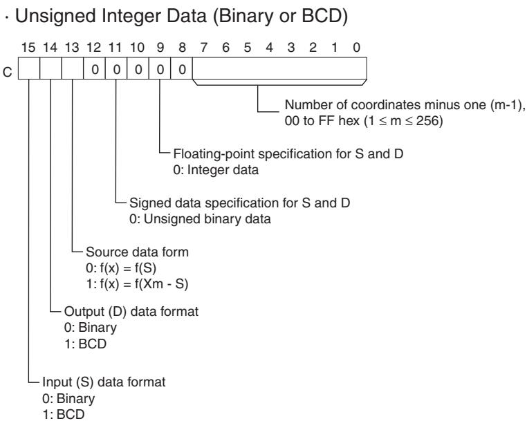
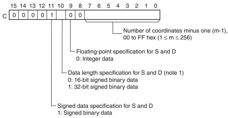
Signed Integer Data (Binary)
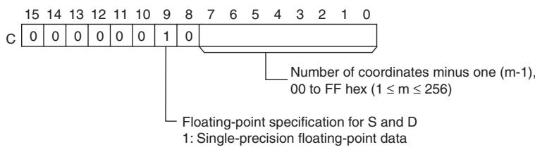
- Single-precision Floating-point Data
16-bit BCD16-bit binary (signed or unsigned) or 16-bit BCD data
| C+1 | X0 (*1) |
| C+2 | Y0 |
| C+3 | X1 |
| C+4 | Y1 |
| C+5 | X2 |
| C+6 | Y2 |
| Xn | |
| Yn | |
| C+ (2m+1) | Xm |
| C+ (2m+2) | Ym |
Note: Write Xm (max. X value in the table) in word C+1 when the I/O data in S and D contain unsigned data (bit 11 of C = 0).
32-bit signed binary data
| C+1 | X0 (rightmost 16 bits) |
| C+2 | X0 (leftmost 16 bits) |
| C+3 | Y0 (rightmost 16 bits) |
| C+4 | Y0 (leftmost 16 bits) |
| C+5 | X1 (rightmost 16 bits) |
| C+6 | X1 (leftmost 16 bits) |
| C+7 | Y1 (rightmost 16 bits) |
| C+8 | Y1 (leftmost 16 bits) |
| to | to |
| C+ (4n+1) | Xn (rightmost 16 bits) |
| C+ (4n+2) | Xn (leftmost 16 bits) |
| C+ (4n+3) | Yn (rightmost 16 bits) |
| C+ (4n+4) | Yn (leftmost 16 bits) |
| to | to |
| C+ (4m+1) | Xm (rightmost 16 bits) |
| C+ (4m+2) | Xm (leftmost 16 bits) |
| C+ (4m+3) | Ym (rightmost 16 bits) |
| C+ (4m+4) | Ym (leftmost 16 bits) |
Floating-point data
| C+1 | X0 (rightmost 16 bits) |
| C+2 | X0 (leftmost 16 bits) |
| C+3 | Y0 (rightmost 16 bits) |
| C+4 | Y0 (leftmost 16 bits) |
| C+5 | X1 (rightmost 16 bits) |
| C+6 | X1 (leftmost 16 bits) |
| C+7 | Y1 (rightmost 16 bits) |
| C+8 | Y1 (leftmost 16 bits) |
| to | to |
| C+ (4n+1) | Xn (rightmost 16 bits) |
| C+ (4n+2) | Xn (leftmost 16 bits) |
| C+ (4n+3) | Yn (rightmost 16 bits) |
| C+ (4n+4) | Yn (leftmost 16 bits) |
| to | to |
| C+ (4m+1) | Xm (rightmost 16 bits) |
| C+ (4m+2) | Xm (leftmost 16 bits) |
| C+ (4m+3) | Ym (rightmost 16 bits) |
| C+ (4m+4) | Ym (leftmost 16 bits) |
Note: The X coordinates must be in ascending order: X1 < X2 < < Xm . Input all values of (X_n, Y_n) as binary data, regardless of the data format specified in control word C.
- Operand Specifications
| Area | Word addresses | Indirect DM addresses | Constants | CF | Pulse bits | TR bits | |||||||
| CIO | WR | HR | AR | T | C | DM | @DM | *DM | |||||
| C,S | OK | OK | OK | OK | OK | OK | OK | OK | OK | OK | --- | --- | --- |
| R | --- | ||||||||||||
Flags
| Name | Label | Operation |
| Error Flag | P_ER | ON if C is a constant greater than 0001. ON if C is a word address but the X coordinates are not in ascending order (X1 ≤ X2 ≤ ... ≤ Xm). ON if C is a word address and bits 9, 11, and 15 of C indicate BCD input, but S is not BCD. ON if C is a word address and bit 9 of C indicates floating-point data, but S is a one-word constant. ON if C is 0000 or 0001 but S is not BCD between 0000 and 0900. OFF in all other cases. |
| Equals Flag | P_EQ | ON if the result is 0. OFF in all other cases. |
| Negative Flag | P_N | ON if bit 15 of R is ON. OFF in all other cases. |
Function
Operation of the Linear Extrapolation Function
APR(069) processes the input data specified in S with the following equation and the line-segment data (X_n,Y_n) specified in the table beginning at C + 1 . The result is output to the destination word(s) specified with D.
Up to 256 endpoints can be stored in the line-segment data table beginning at C+1.
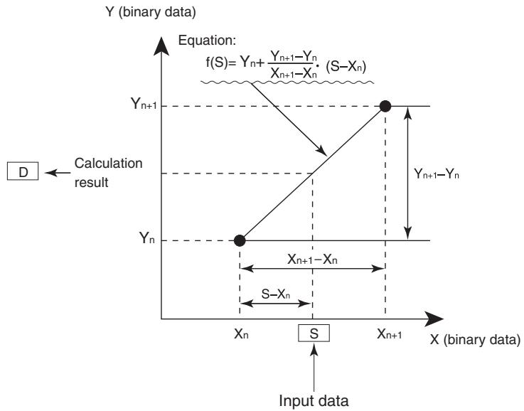
- 16-bit Unsigned BCD Data
The input data and/or the output data can be 16-bit unsigned BCD data. Also, the linear extrapolation function can be set to operate on the value specified in S directly or on X_m -S. (X_m is the maximum value of X in the line-segment data.)
- 16-bit Unsigned Binary Data
The input data and/or the output data can be 16-bit unsigned binary data. Also, the linear extrapolation function can be set to operate on the value specified in S directly or on X_m -S. ( X_m is the maximum value of X in the line-segment data.)
- 16-bit Signed Binary Data
- 32-bit Signed Binary Data
| Setting name | Bit in C | Setting |
| Input data (S) format | 15 | 0: Binary 1: BCD |
| Output data (D) format | 14 | 0: Binary 1: BCD |
| Source data form | 13 | 0: Operate on S 1: Operate on Xm-S |
| Signed data specification for S and D | 11 | 0: Unsigned data |
| Data length specification for S and D | 10 | Invalid (fixed at 16 bits) |
| Floating-point specification | 09 | 0: Integer data |
| Setting name | Bit in C | Setting |
| Input data (S) format | 15 | 0: Binary |
| Output data (D) format | 14 | 0: Binary |
| Source data form | 13 | 0 |
| Signed data specification for S and D | 11 | 1: Signed data |
| Data length specification for S and D | 10 | 0: 16-bit signed binary data |
| Floating-point specification | 09 | 0: Integer data |
| Setting name | Bit in C | Setting |
| Input data (S) format | 15 | 0: Binary |
| Output data (D) format | 14 | 0: Binary |
| Source data form | 13 | 0 |
| Signed data specification for S and D | 11 | 1: Signed data |
| Data length specification for S and D | 10 | 1: 32-bit signed binary data |
| Floating-point specification | 09 | 0: Integer data |
Note If the "Data length specification for S and D" in bit 10 of C is set to 1 and a 16-bit constant is input for S, the input data will be converted to 32-bit signed binary before the linear extrapolation calculation.
- Floating-point Data
| Setting name | Bit in C | Setting |
| Input data (S) format | 15 | 0 |
| Output data (D) format | 14 | 0 |
| Source data form | 13 | 0 |
| Signed data specification for S and D | 11 | 0 |
| Data length specification for S and D | 10 | 0 |
| Floating-point specification | 09 | 1: Floating-point data |
Note If the "Floating-point specification" in bit 09 of C is set to 1, a constant cannot be input for S.
Sample program
- Sine Function (C: #0000)
The following example shows APR(069) used to calculate the sine of 30^ .
$$ (S I N (3 0) = 0. 5 0 0 0) $$
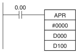
Source data
| S: D0 | |||
| 0 | ×10^1 | ×10^0 | ×10^-1 |
| 0 | 3 | 0 | 0 |
Set the source data in × 10^-1 degrees. (0000 to 0900, BCD)
Result
| R: D100 | |||
| ×10-1 | ×10-2 | ×10-3 | ×10-4 |
| 5 | 0 | 0 | 0 |
Result data has four significant digits, fifth and higher digits are ignored. (0000 to 9999, BCD)
- Cosine Function (C: #0001)
The following example shows APR(069) used to calculate the cosine of 30^ .
$$ (\operatorname {C O S} (3 0) = 0. 8 6 6 0) $$

Source data
| S: D10 | |||
| 0 | ×10^1 | ×10^0 | ×10^-1 |
| 0 | 3 | 0 | 0 |
Set the source data in × 10^-1 degrees. (0000 to 0900, BCD)
Result
| R: D100 | |||
| ×10-1 | ×10-2 | ×10-3 | ×10-4 |
| 8 | 6 | 6 | 0 |
Result data has four significant digits, fifth and higher digits are ignored. (0000 to 9999, BCD)
- Linear Extrapolation (C: Word Address)
- Using 16-bit Unsigned BCD or Binary Data APR(069) processes the input data specified in S based on the control data in C and the line-segment data specified in the table beginning at C + 1 . The result is output to D.
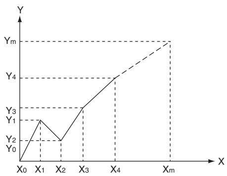
- Y_n = f(X_n), Y_0 = f(X_0)
- Be sure that X_n - 1 < X_n in all cases.
- Input all values of (X_n, Y_n) as binary data.
| Word | Coordinate |
| C+1 | Xm (max. X value) |
| C+2 | Y0 |
| C+3 | X1 |
| C+4 | Y1 |
| C+5 | X2 |
| C+6 | Y2 |
| ↓ | ↓ |
| C+(2m+1) | Xm (max. X value) |
| C+(2m+2) | Ym |
This example shows how to construct a linear extrapolation with 12 coordinates. The block of data is continuous, as it must be, from D0 to D26 (C to C + (2 × 12 + 2) ). The input data is taken from CIO 10, and the result is output to CIO 11.
| 0.00 |
| APR |
| D0 |
| 10 |
| 11 |
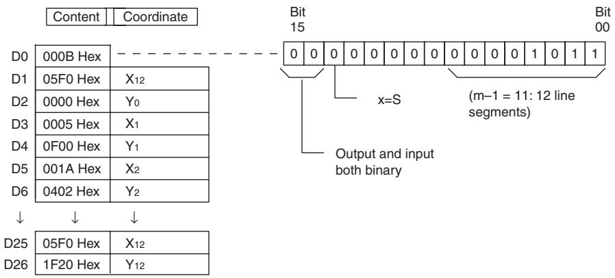
In this case, the source word, CIO 0010, contains 0014, and f(0014) = 0726 is output to R, CIO 0011.
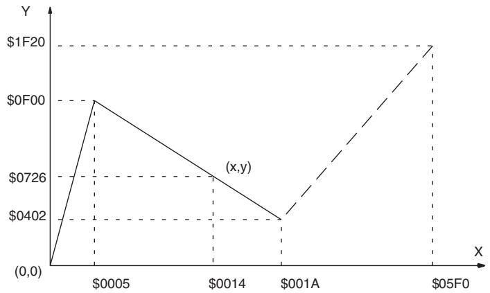
The linear-extrapolation calculation is shown below.
= 0726 Values are all hexadecimal (Hex).
$$ \begin{array}{l} Y = 0 F 0 0 + \frac {0 4 0 2 - 0 F 0 0}{0 0 1 A - 0 0 0 5} \times (0 0 1 4 - 0 0 1 5) \ = 0 F 0 0 - (0 0 8 6 \times 0 0 0 F) \ \end{array} $$
- Using 32-bit Signed Binary Data
In this example, APR(069) is used to convert the fluid height in a tank to fluid volume based on the shape of the holding tank.
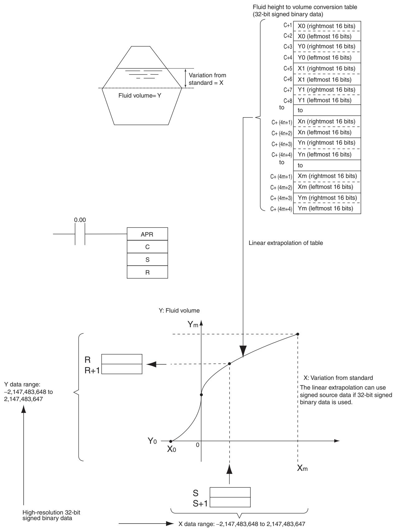
- Using Floating-point Data In this example, APR(069) is used to convert the fluid height in a tank to fluid volume based on the shape of the holding tank.
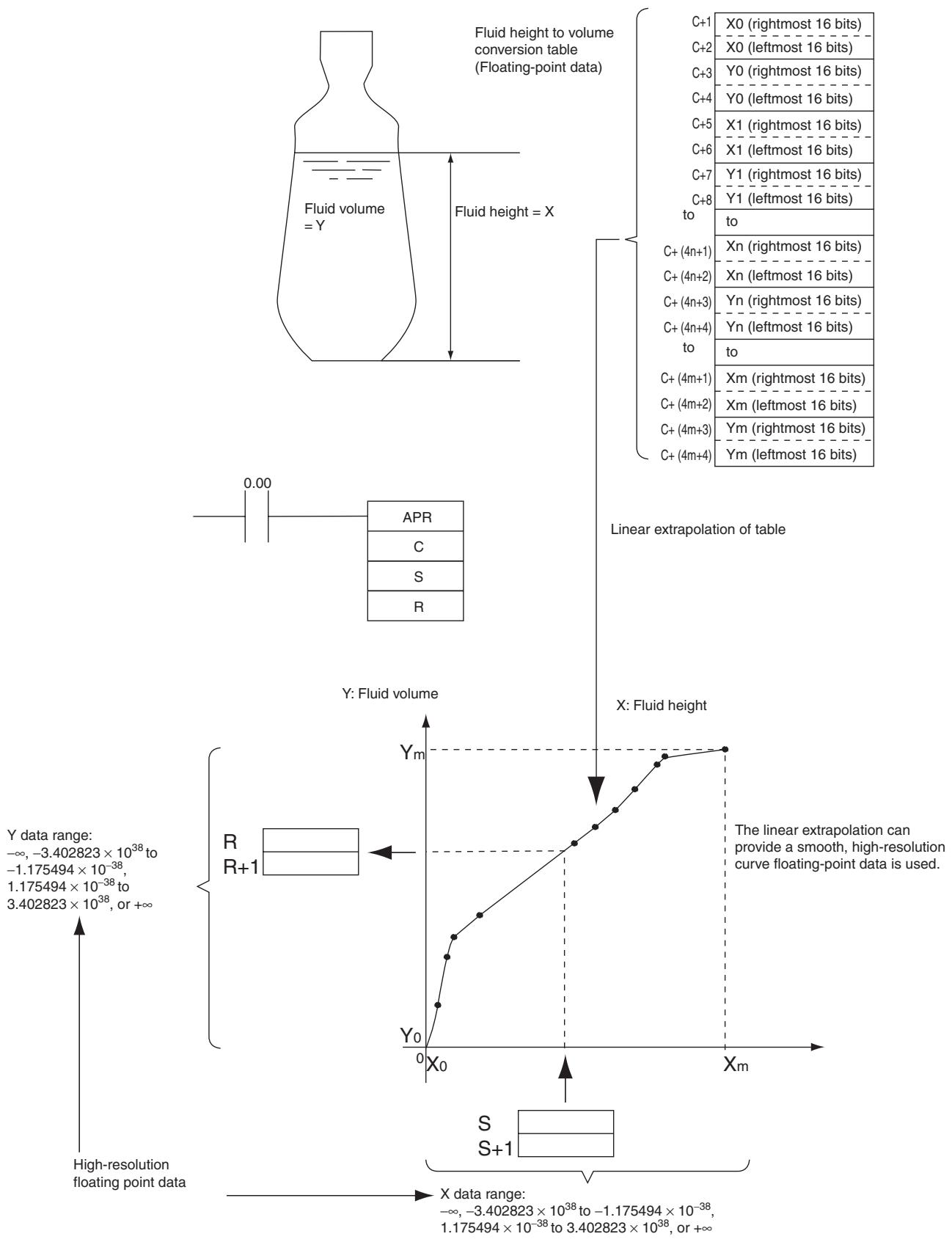
BCNT
| Instruction | Mnemonic | Variations | Function code | Function |
| BIT COUNTER | BCNT | @BCNT | 067 | Counts the total number of ON bits in the specified word(s). |
| Symbol | BCNT | |
| — | BCNT(067) | |
| N | ||
| S | ||
| R | ||
| N: Number of words | ||
| S: First source word | ||
| R: Result word | ||
Applicable Program Areas
| Area | Step program areas | Subroutines | Interrupt tasks |
| Usage | OK | OK | OK |
Operands
| Operand | Description | Data type | Size |
| N | Number of words | UINT | 1 |
| S | First source word | UINT | Variable |
| R | Result word | UINT | 1 |
N: Number of words
The number of words must be 0001 to FFFF (1 to 65,535 words).
-Operand Specifications
| Area | Word addresses | Indirect DM addresses | Constants | CF | Pulse bits | TR bits | |||||||
| CIO | WR | HR | AR | T | C | DM | @DM | *DM | |||||
| N | OK | OK | OK | OK | OK | OK | OK | OK | OK | OK | --- | --- | --- |
| S,R | --- | ||||||||||||
Flags
| Name | Label | Operation |
| Error Flag | P_ER | ON if N is 0000. ON if result exceeds FFFF. OFF in all other cases. |
| Equals Flag | P_EQ | ON if the result is 0000. OFF in all other cases. |
Function
BCNT(067) counts the total number of bits that are ON in all words between S and S + (N - 1) and places the result in R.
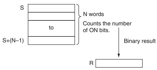
Precautions
- Some time will be required to complete BCNT(067) if a large number of words is specified. Even if an interrupt occurs, execution of this instruction will not be interrupted and execution of the interrupt task will be started after execution of BCNT(067) has been completed. One BCNT(067) instruction can be replaced with two BCNT(067) instructions to help avoid this problem.
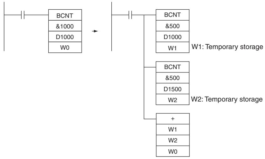
Sample Program
When CIO 0.00 is ON in the following example, BCNT(067) counts the total number of ON bits in the 10 words from CIO 100 through CIO 109 and writes the result to D100.
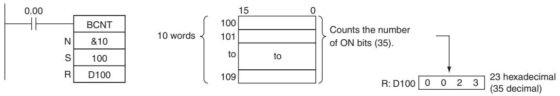
Floating-point Math Instructions
The Floating-point Math Instructions convert data and perform floating-point arithmetic operations.
Data Format
Floating-point data expresses real numbers using a sign, exponent, and mantissa. When data is expressed in floating-point format, the following formula applies.
Real number = (-1)^S2^e - 127 (1.f)
s: Sign
e: Exponent
f: Mantissa
The floating-point data format conforms to the IEEE754 standards. Data is expressed in 32 bits, as follows:
| Sign | Exponent | Mantissa | |||
| s | e | f | |||
| 31 | 30 | 23 | 22 | 0 | |
| Data | No. of bits | Contents |
| s: sign | 1 | 0: positive; 1: negative |
| e: exponent | 8 | The exponent (e) value ranges from 0 to 255. The actual exponent is the value remaining after 127 is subtracted from e, resulting in a range of -127 to 128. “e=0” and “e=255” express special numbers. |
| f: mantissa | 23 | The mantissa portion of binary floating-point data fits the formal 2.0 > 1.f ≥1.0. |
Number of Digits
The number of effective digits for floating-point data is seven digits for decimal.
- Floating-point Data
The following data can be expressed by floating-point data:
-oo
- -3.402823 × 10^38 ≤ value ≤ -1.175494 × 10^-38
0
1. 1.175494 × 10^-38 ≤ value ≤ 3.402823 × 10^38
+00
Not a number (NaN)
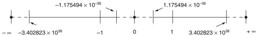
- Special Numbers
The formats for NaN, ± , and 0 are as follows:
- NaN^*:e = 255, f 0
+ : e = 255, f = 0, s = 0 - - : e = 255, f = 0, s = 1
0: e = 0 f = 0 - NaN (not a number) is not a valid floating-point number. Executing floating-point calculation instructions will not result in NaN.
- Writing Floating-point Data
When floating-point is specified for the data format in the I/O memory edit display in the CX-Programmer, standard decimal numbers input in the display are automatically converted to the floating-point format shown above (IEEE754-format) and written to I/O Memory. Data written in the IEEE754-format is automatically converted to standard decimal format when monitored on the display.
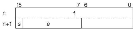
It is not necessary for the user to be aware of the IEEE754 data format when reading and writing floating-point data. It is only necessary to remember that floating point values occupy two words each.
- Numbers Expressed as Floating-point Values
The following types of floating-point numbers can be used.
| Mantissa (f) | Exponent (e) | ||
| 0 | Not 0 and not all 1's | All 1's (255) | |
| 0 | 0 | Normalized number | Infinity |
| Not 0 | Non-normalized number | NaN | |
Note A non-normalized number is one whose absolute value is too small to be expressed as a normalized number. Non-normalized numbers have fewer significant digits. If the result of calculations is a non-normalized number (including intermediate results), the number of significant digits will be reduced.
(1) Normalized Numbers
Normalized numbers express real numbers. The sign bit will be 0 for a positive number and 1 for a negative number.
The exponent (e) will be expressed from 1 to 254, and the real exponent will be 127 less, i.e., -126 to 127.
The mantissa (f) will be expressed from 0 to 2^33 - 1 , and it is assumed that, in the real mantissa, bit 2^33 is 1 and the binary point follows immediately after it.
Normalized numbers are expressed as follows:
(-1)(sign s) × 2^(exponent e) - 127 × (1 + mantissa × 2^-23)
Example
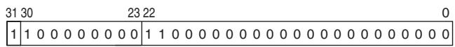
Sign:
Exponent: 128 - 127 = 1
Mantissa: 1 + (2^22 + 2^21) × 2^-23 = 1 + (2^-1 + 2^-2) = 1 + 0.75 = 1.75
Value: -1.75 × 2^1 = -3.5
(2) Non-normalized Numbers
Non-normalized numbers express real numbers with very small absolute values. The sign bit will be 0 for a positive number and 1 for a negative number.
The exponent (e) will be 0, and the real exponent will be -126.
The mantissa (f) will be expressed from 1 to 2^33 - 1 , and it is assume that, in the real mantissa, bit 2^33 is 0 and the binary point follows immediately after it.
Non-normalized numbers are expressed as follows:
$$ (- 1) ^ {(\text {s i g n} s)} \times 2 ^ {- 1 2 6} \times (\text {m a n t i s s a} \times 2 ^ {- 2 3}) $$
Example
| 31 30 | 23 22 | 0 |
| 0 | 0 0 0 0 0 0 0 0 0 | 1 1 0 0 0 0 0 0 0 0 0 0 0 0 0 0 0 0 0 0 0 |
Sign:
Exponent: -126
Mantissa: 0 + (2^22 + 2^21) × 2^-23 = 0 + (2^-1 + 2^-2) = 0 + 0.75 = 0.75
Value: -0.75 × 2^-126
(3) Zero
Values of +0.0 and -0.0 can be expressed by setting the sign to 0 for positive or 1 for negative. The exponent and mantissa will both be 0. Both +0.0 and -0.0 are equivalent to 0.0. Refer to Floating-point Arithmetic Results, below, for differences produced by the sign of 0.0.
(4) Infinity
Values of + and - can be expressed by setting the sign to 0 for positive or 1 for negative. The exponent will be 255 (28 - 1) and the mantissa will be 0.
(5) NaN
NaN (not a number) is produced when the result of calculations, such as 0.0 / 0.0 , / , or - , does not correspond to a number or infinity. The exponent will be 255 ( 2^8 - 1 ) and the mantissa will be not 0.
Note There are no specifications for the sign of NaN or the value of the mantissa field (other than to be not 0).
- Floating-point Arithmetic Results
(1) Rounding Results
The following methods will be used to round results when the number of digits in the accurate result of floating-point arithmetic exceeds the significant digits of internal processing expressions.
If the result is close to one of two internal floating-point expressions, the closer expression will be used.
If the result is midway between two internal floating-point expressions, the result will be rounded so that the last digit of the mantissa is 0.
(2) Overflows, Underflows, and Illegal Calculations
Overflows will be output as either positive or negative infinity, depending on the sign of the result. Underflows will be output as either positive or negative zero, depending on the sign of the result.
Illegal calculations will result in NaN. Illegal calculations include adding infinity to a number with the opposite sign, subtracting infinity from a number with the opposite sign, multiplying zero and infinity, dividing zero by zero, or dividing infinity by infinity.
The value of the result may not be correct if an overflow occurs when converting a floating-point number to an integer.
(3) Precautions in Handling Special Values
The following precautions apply to handling zero, infinity, and NaN.
- The sum of positive zero and negative zero is positive zero.
- The difference between zeros of the same sign is positive zero.
- If any operand is a NaN, the Error Flag will be turned ON and the tests will not be executed.
- Positive zero and negative zero are treated as equivalent in comparisons.
- Comparison or equivalency tests on one or more NaN will not be executed and the Error Flag will be turned ON.
- Floating-point Calculation Results
When the absolute value of the result is greater than the maximum value that can be expressed for floating-point data, the Overflow Flag will turn ON and the result will be output as ± . If the result is positive, it will be output as + ; if negative, then - .
The Equals Flag will only turn ON when both the exponent (e) and the mantissa (f) are zero after a calculation. A calculation result will also be output as zero when the absolute value of the result is less than the minimum value that can be expressed for floating-point data. In that case the Underflow Flag will turn ON.
FIX/FIXL
| Instruction | Mnemonic | Variations | Function code | Function |
| FLOATING TO 16-BIT | FIX | @FIX | 450 | Converts a 32-bit floating-point value to 16-bit signed binary data and places the result in the specified result word. |
| FLOATING TO 32-BIT | FIXL | @FIXL | 451 | Converts a 32-bit floating-point value to 32-bit signed binary data and places the result in the specified result words. |
| Symbol | FIX | FIXL | ||
| FIX(450)S R | S: First source wordR: Result word | FIXL(451)S R | S: First source wordR: First result word | |
Applicable Program Areas
| Area | Step program areas | Subroutines | Interrupt tasks |
| Usage | OK | OK | OK |
Operands
| Operand | Description | Data type | Size | ||
| FIX | FIXL | FIX | FIXL | ||
| S | First source word | REAL | REAL | 2 | 2 |
| R | First result word | INT | DINT | 1 | 2 |
-Operand Specifications
| Area | Word addresses | Indirect DM addresses | Constants | CF | Pulse bits | TR bits | |||||||
| CIO | WR | HR | AR | T | C | DM | @DM | *DM | |||||
| S | OK | OK | OK | OK | OK | OK | OK | OK | OK | OK | --- | --- | --- |
| R | --- | ||||||||||||
Flags
| Name | Label | Operation |
| Error Flag | P_ER | FIX ON if the integer portion of S+1 and S is not within the range of -32,768 to 32,767. FIXL ON if the integer portion of S+1 and S is not within the range of -2,147,483,648 to 2,147,483,647. ON if the data in S+1 and S is not a number (NaN). OFF in all other cases. |
| Equals Flag | P_EQ | ON if the result is 0000. OFF in all other cases. |
| Negative Flag | P_N | ON when the leftmost bit of the result is 1. OFF in all other cases. |
Function
FIX
FIX(450) converts the integer portion of the 32-bit floating-point number in S+1 and S (IEEE754-format) to 16-bit signed binary data and places the result in R.
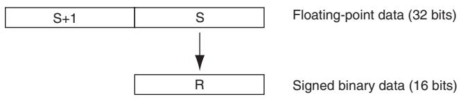
Only the integer portion of the floating-point data is converted, and the fraction portion is truncated.
Example conversions:
A floating-point value of 3.5 is converted to 3.
A floating-point value of -3.5 is converted to -3 .
- FIXL
FIXL(451) converts the integer portion of the 32-bit floating-point number in S+1 and S (IEEE754-format) to 32-bit signed binary data and places the result in R+1 and R.
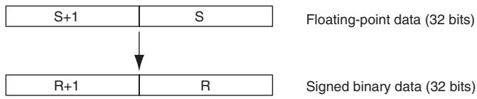
Only the integer portion of the floating-point data is converted, and the fraction portion is truncated.
Example conversions:
A floating-point value of 2,147,483,640.5 is converted to 2,147,483,640. A floating-point value of -214,748,340.5 is converted to -214,748,340 .
FLT/FLTL
| Instruction | Mnemonic | Variations | Function code | Function |
| 16-BIT TO FLOATING | FLT | @FLT | 452 | Converts a 16-bit signed binary value to 32-bit floating-point data and places the result in the specified result words. |
| 32-BIT TO FLOATING | FLTL | @FLTL | 453 | Converts a 32-bit signed binary value to 32-bit floating-point data and places the result in the specified result words. |
| Symbol | FLT | FLTL | ||
| FLT(452)S | S: Source wordR: First result word | FLTL(453)S | S: First source wordR: First result word | |
Applicable Program Areas
| Area | Step program areas | Subroutines | Interrupt tasks |
| Usage | OK | OK | OK |
Operands
| Operand | Description | Data type | Size | ||
| FLT | FLTL | FLT | FLTL | ||
| S | First source word | INT | DINT | 1 | 2 |
| R | First result word | REAL | REAL | 2 | 2 |
- Operand Specifications
| Area | Word addresses | Indirect DM addresses | Constants | CF | Pulse bits | TR bits | |||||||
| CIO | WR | HR | AR | T | C | DM | @DM | *DM | |||||
| S | OK | OK | OK | OK | OK | OK | OK | OK | OK | OK | --- | --- | --- |
| R | --- | ||||||||||||
Flags
| Name | Label | Operation |
| Error Flag | P_ER | OFF |
| Equals Flag | P_EQ | ON if both the exponent and mantissa of the result are 0. OFF in all other cases. |
| Negative Flag | P_N | ON if the result is negative. OFF in all other cases. |
Function
- FLT
FLT(452) converts the 16-bit signed binary value in S to 32-bit floating-point data (IEEE754-format) and places the result in R+1 and R. A single 0 is added after the decimal point in the floating-point result.
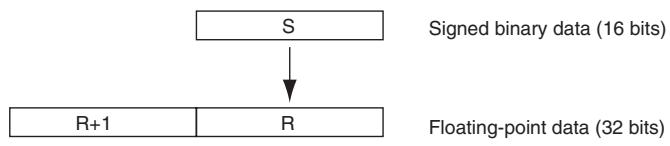
Only values within the range of -32,768 to 32,767 can be specified for S. To convert signed binary data outside of that range, use FLTL(453).
Example conversions:
A signed binary value of 3 is converted to 3.0. A signed binary value of -3 is converted to -3.0.
- FLTL
FLTL(453) converts the 32-bit signed binary value in S + 1 and S to 32-bit floating-point data (IEEE754-format) and places the result in R + 1 and R . A single 0 is added after the decimal point in the floating-point result.
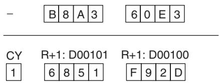
Signed binary data within the range of -2,147,483,648 to 2,147,483,647 can be specified for S+1 and S. The floating point value has 24 significant binary digits (bits). The result will not be exact if a number greater than 16,777,215 (the maximum value that can be expressed in 24-bits) is converted by FLTL(453).
Example Conversions:
A signed binary value of 16,777,215 is converted to 16,777,215.0. A signed binary value of -16,777,215 is converted to -16,777,215.0 .
$$ + F, - F, * F, / F $$
| Instruction | Mnemonic | Variations | Function code | Function |
| FLOATING-POINT ADD | +F | @+F | 454 | Adds two 32-bit floating-point numbers and places the result in the specified result words. |
| FLOATING-POINT SUBTRACT | -F | @-F | 455 | Subtracts one 32-bit floating-point number from another and places the result in the specified result words. |
| FLOATING-POINT MULTIPLY | *F | @*F | 456 | Multiplies two 32-bit floating-point numbers and places the result in the specified result words. |
| FLOATING-POINT DIVIDE | /F | @/F | 457 | Divides one 32-bit floating-point number by another and places the result in the specified result words. |
| Symbol | +F | -F | ||
| +F(454)Au | Au: First augend wordAD: First addend wordR: First result word | -F(455)Mi | Mi: First Minuend wordSu: First Subtrahend wordR: First result word | |
| Su | Su: First Subtrahend wordR: First result word | |||
| +F | /F | |||
| +F(456)Md | Md: First Multipicand wordMr: First Multiplier wordR: First result word | /F(457)Dd | Dd: First Dividend wordDr: First Divisor wordR: First result word | |
| Dd | ||||
| Dr | ||||
| R | ||||
Applicable Program Areas
| Area | Step program areas | Subroutines | Interrupt tasks |
| Usage | OK | OK | OK |
Operands
| Operand | Description | Data type | Size | |
| +F | Au | First augend word | REAL | 2 |
| AD | First addend word | |||
| -F | Mi | First Minuend word | REAL | 2 |
| Su | First Subrahend word | |||
| *F | Md | First Multipicand word | REAL | 2 |
| Mr | First Multiplier word | |||
| /F | Dd | First Dividend word | REAL | 2 |
| Dr | First Divisor word | |||
| R | First result word | REAL | 2 | |
- Operand Specifications
| Area | Word addresses | Indirect DM addresses | Constants | CF | Pulse bits | TR bits | |||||||
| CIO | WR | HR | AR | T | C | DM | @DM | *DM | |||||
| Au, AD, Mi, Su, Md, Mr, Dd, Dr | OK | OK | OK | OK | OK | OK | OK | OK | OK | OK | --- | --- | --- |
| R | --- | ||||||||||||
Flags
| Name | Label | Operation |
| Error Flag | P_ER | +FON if the augend or addend data is not a number (NaN).ON if +∞ and -∞ are added.-FON if the minuend or subtrahend is not a number (NaN).ON if +∞ is subtracted from +∞.ON if -∞ is subtracted from -∞.*FON if the multiplicand or multiplier is not a number (NaN).ON if +∞ and 0 are multiplied.ON if -∞ and 0 are multiplied./FON if the dividend or divisor is not a number (NaN).ON if the dividend and divisor are both 0.ON if the dividend and divisor are both +∞ or -∞.OFF in all other cases. |
| Equals Flag | P_EQ | ON if both the exponent and mantissa of the result are 0 OFF in all other cases. |
| Overflow Flag | P_OF | ON if the absolute value of the result is too large to be expressed as a 32-bit floating-point value.OFF in all other cases. |
| Underflow Flag | P_UF | ON if the absolute value of the result is too small to be expressed as a 32-bit floating-point value.OFF in all other cases. |
| Negative Flag | P_N | ON if the result is negative.OFF in all other cases. |
Function
The data specified in Au/Mi/Md/Dd and the data specified in AD/Su/Mr/Dr are added (+F), subtracted (-F), multiplied (*F), or divided (/F) as single-precision floating-point data (32 bits: IEEE754) and output to R+1, R.
+F
| Au+1 | Au |
Augend (floating-point data, 32 bits)
| + | Ad+1 | Ad |
Addend (floating-point data, 32 bits)
| R+1 | R |
Result (floating-point data, 32 bits)
-F
| Mi+1 | Mi |
Minuend (floating-point data, 32 bits)
| Su+1 | Su |
Subrahend (floating-point data, 32 bits)
| R+1 | R |
Result (floating-point data, 32 bits)
*F
| Md+1 | Md | Multiplier (floating-point data, 32 bits) |
| × Mr+1 | Mr | |
| R+1 | R | Result (floating-point data, 32 bits) |
/F
| Dd+1 | Dd | Dividend (floating-point data, 32 bits) |
| Dr+1 | Dr | Divisor (floating-point data, 32 bits) |
| R+1 | R | Result (floating-point data, 32 bits) |
- If the absolute value of the result is greater than the maximum value that can be expressed as floating-point data, the Overflow Flag will turn ON and the result will be output as ± .
- If the absolute value of the result is less than the minimum value that can be expressed as floating-point data, the Underflow Flag will turn ON and the result will be output as 0.
Operation rules
The result of an operation is output as shown below depending on the combination of floating-point data.
- FLOATING-POINT ADD (+F)
| Augend | |||||
| Addend | 0 | Numeral | +∞ | -∞ | NaN |
| 0 | 0 | Numeral | +∞ | -∞ | |
| Numeral | Numeral | See note 1. | +∞ | -∞ | |
| +∞ | +∞ | +∞ | +∞ | ER | |
| -∞ | -∞ | -∞ | ER | -∞ | |
| NaN | ER | ||||
Note 1 The results could be zero (including underflows), a numeral, + , or - .
ER The Error Flag will be turned ON and the instruction will not be executed.
- FLOATING-POINT SUBTRACT (-F)
| Minuend | |||||
| Subtrahend | 0 | Numeral | +∞ | -∞ | NaN |
| 0 | 0 | Numeral | +∞ | -∞ | |
| Numeral | Numeral | See note 1. | +∞ | -∞ | |
| +∞ | -∞ | -∞ | ER | -∞ | |
| -∞ | +∞ | +∞ | +∞ | ER | |
| NaN | ER | ||||
Note 1 The results could be zero (including underflows), a numeral, + , or - .
ER The Error Flag will be turned ON and the instruction will not be executed.
- FLOATING-POINT MULTIPLY (*F)
| Multipicand | |||||
| Multiplier | 0 | Numeral | +∞ | -∞ | NaN |
| 0 | 0 | 0 | ER | ER | |
| Numeral | 0 | See note 1. | +/-∞ | +/-∞ | |
| +∞ | ER | +/-∞ | +∞ | -∞ | |
| -∞ | ER | +/-∞ | -∞ | +∞ | |
| NaN | ER | ||||
Note 1 The results could be zero (including underflows), a numeral, + , or - .
ER The Error Flag will be turned ON and the instruction will not be executed.
- FLOATING-POINT DIVIDE (/F)
| Dividend | |||||
| Divisor | 0 | Numeral | +∞ | -∞ | NaN |
| 0 | ER | +/-∞ | +∞ | -∞ | |
| Numeral | 0 | See note 2. | +/-∞ | +/-∞ | |
| +∞ | 0 | 0 (See note 1) | ER | ER | |
| -∞ | 0 | 0 (See note 1) | ER | ER | |
| NaN | ER | ||||
Note 1 The results will be zero for underflows.
2 The results could be zero (including underflows), a numeral, + , or - .
ER The Error Flag will be turned ON and the instruction will not be executed.
$$ = F, < > F, < F, < = F, > F, > = F $$
| Instruction | Mnemonic | Variations | Function code | Function |
| Single-precision Floating-point Comparison | =F | --- | 329 | These input comparison instructions compare two single-precision floating point values (32-bit IEEE754 constants and/or the contents of speci-fied words) and create an ON execution condition when the comparison condition is true. |
| <>F | 330 | |||
| <F | 331 | |||
| <=F | 332 | |||
| >F | 333 | |||
| >=F | 334 |
| Symbol | Single-precision Floating-point Comparison | |||||
| LD connection | AND connection | OR connection | ||||
| Mnemonic | Mnemonic | S1: Comparison data 1 | S1: Comparison data 1 | S1: Comparison data 2 | S1: Comparison data 2 | |
| S1 | S2 | S2: Comparison data 2 | S2: Comparison data 2 | S2: Comparison data 2 | S2: Comparison data 2 | |
Applicable Program Areas
| Area | Step program areas | Subroutines | Interrupt tasks |
| Usage | OK | OK | OK |
Operands
| Operand | Description | Data type | Size |
| S1 | Comparison data 1 | REAL | 2 |
| S2 | Comparison data 2 | REAL | 2 |
- Operand Specifications
| Area | Word addresses | Indirect DM addresses | Constants | CF | Pulse bits | TR bits | |||||||
| CIO | WR | HR | AR | T | C | DM | @DM | *DM | |||||
| S1, S2 | OK | OK | OK | OK | OK | OK | OK | OK | OK | OK | --- | --- | --- |
Flags
| Name | Label | Operation |
| Error Flag | P_ER | ON if S1+1, S1 or S2+1, S2 is not a number (NaN).ON if S1+1, S1 or S2+1, S2 is +∞.ON if S1+1, S1 or S2+1, S2 is -∞OFF in all other cases. |
| Greater Than Flag | P_GT | ON if S1+1, S1 > S2+1, S2 OFF in all other cases. |
| Greater Than or Equal Flag | P_GE | ON if S1+1, S1 ≥ S2+1, S2. OFF in all other cases. |
| Equal Flag | P_EQ | ON if S1+1, S1 = S2+1, S2. OFF in all other cases. |
| Not Equal Flag | P_NE | ON if S1+1, S1 ≠ S2+1, S2. OFF in all other cases. |
| Less Than Flag | P_LT | ON if S1+1, S1 < S2+1, S2. OFF in all other cases. |
| Less Than or Equal Flag | P_LE | ON if S1+1, S1 ≤ S2+1, S2. OFF in all other cases. |
| Negative Flag | P_N | Unchanged |
Function
The input comparison instruction compares the data specified in S1 and S2 as single-precision floating point values (32-bit IEEE754 data) and creates an ON execution condition when the comparison condition is true.
When the data is stored in words, S1 and S2 specify the first of two words containing the 32-bit data. It is also possible to input the floating-point data as an 8-digit hexadecimal constant.
The input comparison instructions are treated just like the LD, AND, and OR instructions to control the execution of subsequent instructions.
LD: The instruction can be connected directly to the left bus bar.
AND: The instruction cannot be connected directly to the left bus bar.
OR: The instruction can be connected directly to the left bus bar.
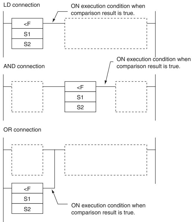
- Options
With the three input types and six symbols, there are 18 different possible combinations.
| Symbol (LD, AND, and OR cannot be used in a ladder program) | Option (data format) |
| LD=, AND=, OR=, LD<>, AND<, OR<, LD<, AND<, OR<, LD>, AND>, OR>, AND>=, AND>=, OR>= | F: Single-precision floating-point data |
| Code | Mnemonic | Name | Function |
| 329 | LD=F | LOAD FLOATING EQUAL | True if S1+1, S1 = S2+1, S2 |
| AND=F | AND FLOATING EQUAL | ||
| OR=F | OR FLOATING EQUAL | ||
| 330 | LD<>F | LOAD FLOATING NOT EQUAL | True if S1+1, S1≠ S2+1, S2 |
| AND<>F | AND FLOATING NOT EQUAL | ||
| OR<>F | OR FLOATING NOT EQUAL | ||
| 331 | LD<F | LOAD FLOATING LESS THAN | True if S1+1, S1 < S2+1, S2 |
| AND<F | AND FLOATING LESS THAN | ||
| OR<F | OR FLOATING LESS THAN | ||
| 332 | LD<=F | LOAD FLOATING LESS THAN OR EQUAL | True if S1+1, S1 ≤ S2+1, S2 |
| AND<=F | AND FLOATING LESS THAN OR EQUAL | ||
| OR<=F | OR FLOATING LESS THAN OR EQUAL | ||
| 333 | LD>F | LOAD FLOATING GREATER THAN | True if S1+1, S1 > S2+1, S2 |
| AND>F | AND FLOATING GREATER THAN | ||
| OR>F | OR FLOATING GREATER THAN | ||
| 334 | LD>=F | LOAD FLOATING GREATER THAN OR EQUAL | True if S1+1, S1 ≥ S2+1, S2 |
| AND>=F | AND FLOATING GREATER THAN OR EQUAL | ||
| OR>=F | OR FLOATING GREATER THAN OR EQUAL |
Precautions
- Input comparison instructions cannot be used as right-hand instructions, i.e., another instruction must be used between them and the right bus bar.
Sample program
When CIO 0.00 is ON in the following example, the floating point data in D101, D100 is compared to the floating point data in D201, D200. If the content of D101, D100 is less than that of D201, D200, execution proceeds to the next line and CIO 50.00 is turned ON. If the content of D101, D100 is not less than that of D201, D200, execution does not proceed to the next instruction line.
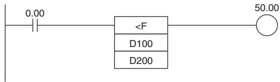
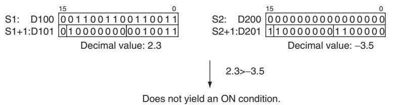
SINGLE FLOATING LESS THAN Comparison (<F)
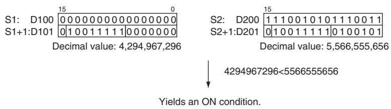
FSTR
| Instruction | Mnemonic | Variations | Function code | Function |
| FLOATING-POINT TO ASCII | FSTR | @FSTR | 448 | Expresses a 32-bit floating-point value (IEEE754-format) in standard decimal notation or scientific notation and converts that value to ASCII text. |
| Symbol | FSTR |
| FSTR(448) | |
| S | |
| C | |
| D |
Applicable Program Areas
| Area | Step program areas | Subroutines | Interrupt tasks |
| Usage | OK | OK | OK |
Operands
| Operand | Description | Data type | Size |
| S | First source word | REAL | 2 |
| C | First control word | UINT | 3 |
| D | First destination word | UINT | Variable |
C: First Control Word
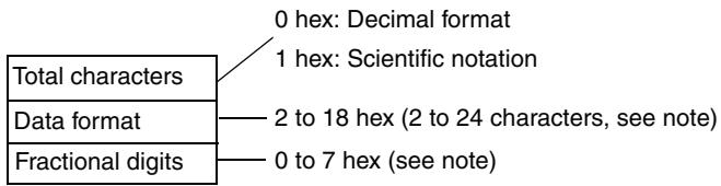
Note There are limits on the total number of characters and the number of fractional digits.
-Operand Specifications
| Area | Word addresses | Indirect DM addresses | Constants | CF | Pulse bits | TR bits | |||||||
| CIO | WR | HR | AR | T | C | DM | @DM | *DM | |||||
| S | OK | OK | OK | OK | OK | OK | OK | OK | OK | OK | --- | --- | --- |
| C, D | --- | ||||||||||||
Flags
| Name | Label | Operation |
| Error Flag | P_ER | ON if the data in S+1 and S is not a valid floating-point number (NaN).ON if the data in S+1 and S is +o or -o.ON if the Data Format setting in C is not 0000 or 0001.ON if the Total Characters setting in C+1 is not within the allowed range. (See 1. Limits on the Total Number of ASCII Characters above for details.)ON if the Fractional Digits setting in C+2 is not within the allowed range. (See 3. Limits on the Number of Digits in the Fractional Part above for details.) |
| Equals Flag | P_EQ | ON if the conversion result is 0OFF in all other cases. |
Function
FSTR(448) expresses the 32-bit floating-point number in S+1 and S (IEEE754-format) in decimal notation or scientific notation according to the control data in words C to C+2, converts the number to ASCII text, and outputs the result to the destination words starting at D.
-
The content of C (Data format) specifies whether to express the number in S + 1 , S in decimal notation or scientific notation.
-
Decimal notation
Expresses a real number as an integer and fractional part.
Example: 124.56
Scientific notation
Expresses a real number as an integer part, fractional part, and exponent part.
Example: 1.2456E-2 (1.2456×10⁻²)
- The content of C + 1 (Total characters) specifies the number of ASCII characters after conversion including the sign symbol, numbers, decimal point and spaces.
- The content of C + 2 (Fractional digits) specifies the number of digits (characters) below the decimal point.
The ASCII text is stored in D and subsequent words in the following order: leftmost byte of D, rightmost byte of D, leftmost byte of D+1, rightmost byte of D+1, etc.
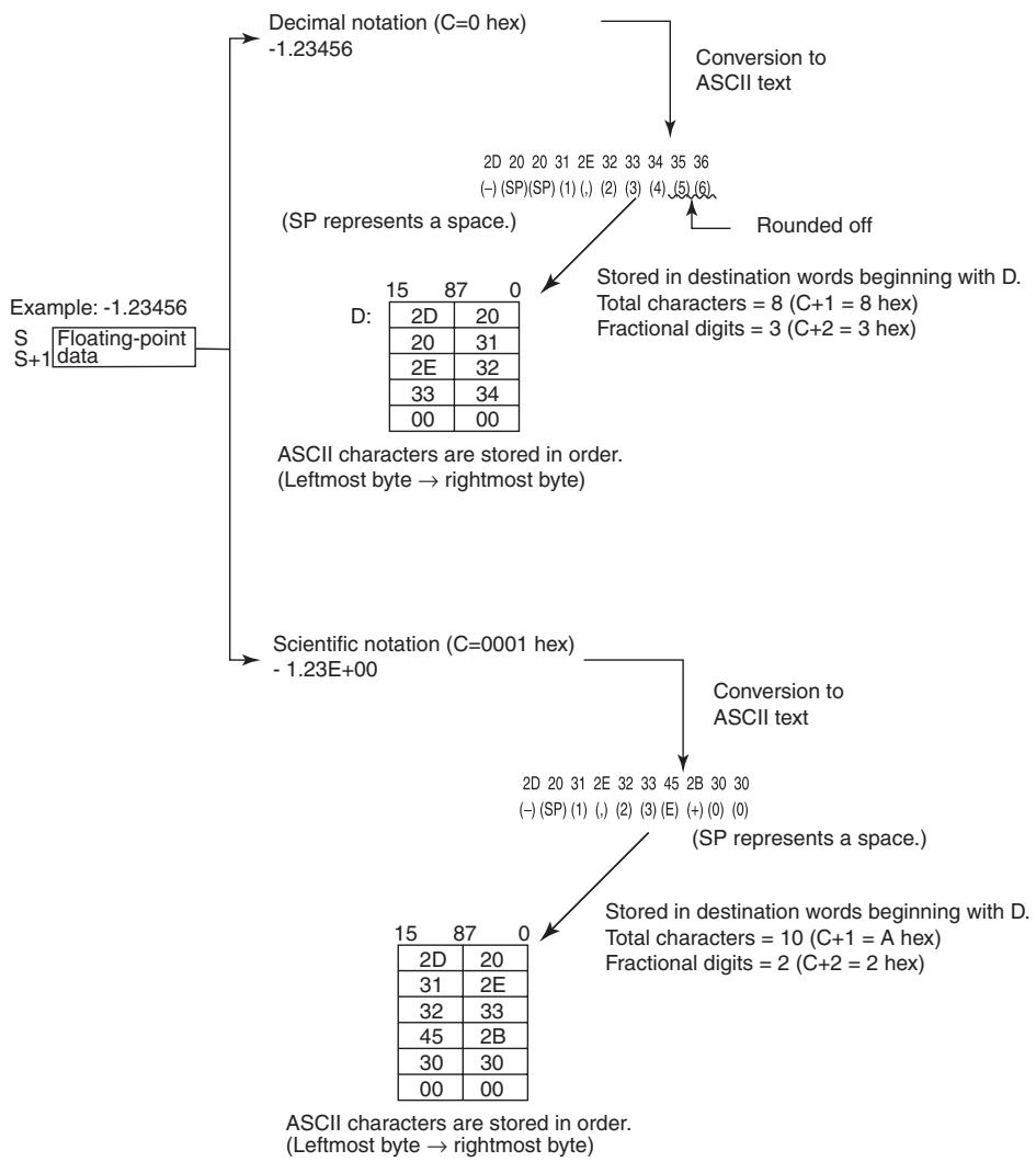
Storage of ASCII Text
After the floating-point number is converted to ASCII text, the ASCII characters are stored in the destination words beginning with D, as shown in the following diagrams. Different storage methods are used for decimal notation and scientific notation.
Decimal notation (C=0 hex)
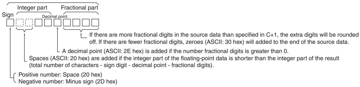
Total number of characters
Scientific notation (C=1 hex)
Total number of characters
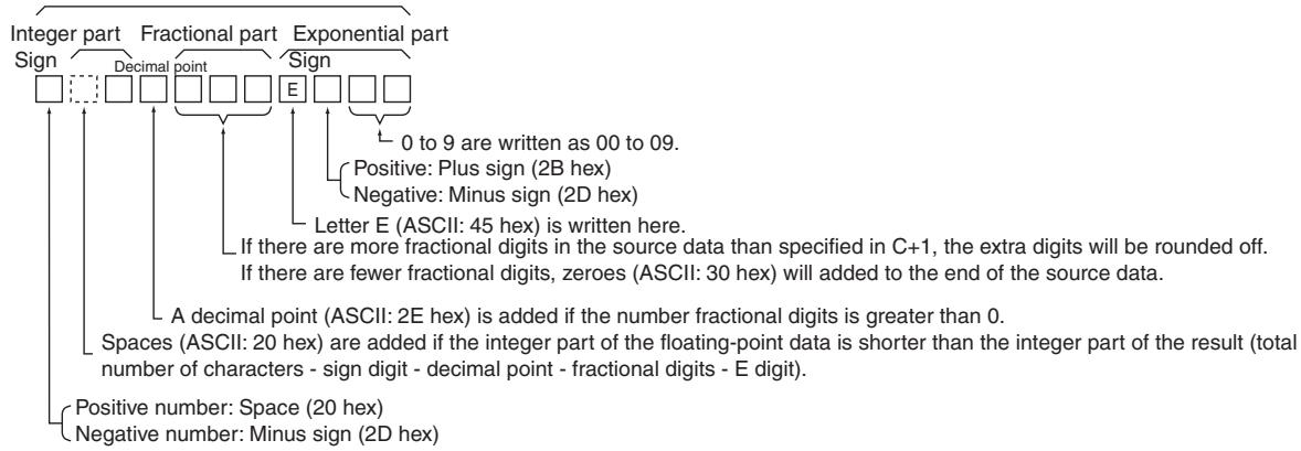
Note Either one or two bytes of zeroes are added to the end of ASCII text as an end code.
- Total number of characters odd: 00 hex is stored after the ASCII text.
- Total number of characters even: 0000 hex is stored after the ASCII text.
- Limits on the Number of ASCII Characters
There are limits on the number of ASCII characters in the converted number. The Error Flag will be turned ON if the number of characters exceeds the maximum allowed.
- Limits on the Total Number of ASCII Characters
1) Decimal Notation (C = 0 hex)
- When there is no fractional part (C + 2 = 0 hex): 2 ≤ Total Characters ≤ 24
- When there is a fractional part (C + 2 = 1 to 7hex) : (Fractional digits +3 ) ≤ Total Characters ≤ 24
2) Scientific Notation (C = 1 hex)
- When there is no fractional part (C + 2 = 0 hex): 6 ≤ Total Characters ≤ 24
-
When there is a fractional part (C + 2 = 1 to 7hex ): (Fractional digits +7 ) ≤ Total Characters ≤ 24
-
Limits on the Number of Digits in the Integer Part
1) Decimal Notation (C = 0 hex)
- When there is no fractional part (C + 2 = 0 hex): 1 ≤ Number of Integer Digits ≤ 24 - 1
- When there is a fractional part (C + 2 = 1 to 7 hex): 1 ≤ Number of Integer Digits ≤ (24 - Fractional digits - 2)
2) Scientific Notation (C = 1 hex) 1 digit (fixed)
- Limits on the Number of Digits in the Fractional Part
1) Decimal Notation (C = 0 hex)
- Fractional Digits ≤ 7
- Also: Fractional Digits ≤ (Total Number of ASCII Characters - 3)
2) Scientific Notation (C =1 hex)
- Fractional Digits ≤ 7
- Also: Fractional Digits ≤ (Total Number of ASCII Characters - 7)
Sample program
- Converting to ASCII Text in Decimal Notation
When CIO 0.00 is ON in the following example, FSTR(448) converts the floating-point data in D1 and D0 to decimal-notation ASCII text and writes the ASCII text to the destination words beginning with D100. The contents of the control words (D10 to D12) specify the details on the data format (decimal notation, 7 characters total, 3 fractional digits).
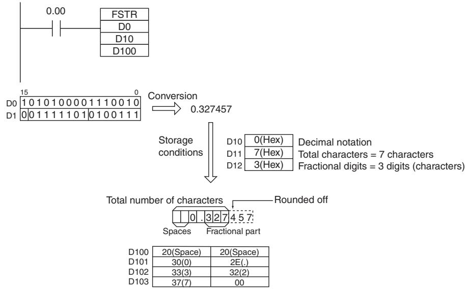
- Converting to ASCII Text in Scientific Notation
When CIO 0.00 is ON in the following example, FSTR(448) converts the floating-point data in D1 and D0 to scientific-notation ASCII text and writes the ASCII text to the destination words beginning with D100. The contents of the control words (D10 to D12) specify the details on the data format (scientific notation, 11 characters total, 3 fractional digits).
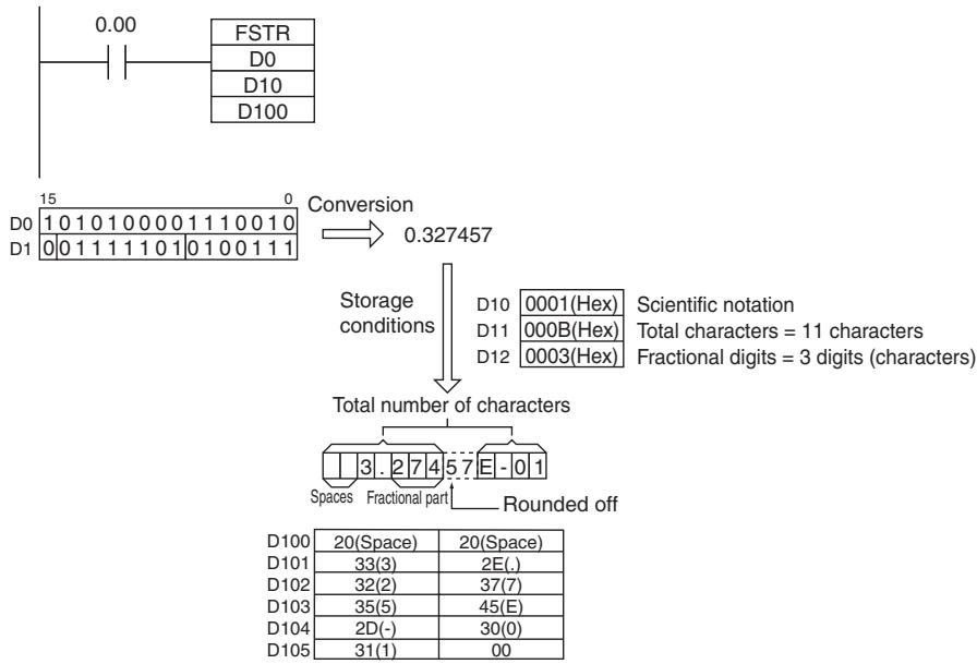
FVAL
| Instruction | Mnemonic | Variations | Function code | Function |
| ASCII TO FLOATING-POINT | FVAL | @FVAL | 449 | Converts a number expressed in ASCII text (decimal or scientific notation) to a 32-bit floating-point value (IEEE754-format) and outputs the floating-point value to the specified words. |
| Symbol | FVAL |
| FVAL(449) | |
| S | |
| D | |
| S: First source word | |
| D: First destination word |
Applicable Program Areas
| Area | Step program areas | Subroutines | Interrupt tasks |
| Usage | OK | OK | OK |
Operands
| Operand | Description | Data type | Size |
| S | First source word | UINT | Variable |
| D | First destination word | REAL | 2 |
- Operand Specifications
| Area | Word addresses | Indirect DM addresses | Constants | CF | Pulse bits | TR bits | |||||||
| CIO | WR | HR | AR | T | C | DM | @DM | *DM | |||||
| S, D | OK | OK | OK | OK | OK | OK | OK | OK | OK | --- | --- | --- | --- |
Flags
| Name | Label | Operation |
| Error Flag | P_ER | ON if the digits (integer and fractional parts) in the source data starting at S are not 30 to 39 hex (0 to 9).ON if the first two digits of the exponential part do not contain 45 and 2B hex (E+) or 45 and 2D hex (E-). in the source data starting at S are not 30 to 39 hex (0 to 9).ON if there are two or more exponential parts in the source data.ON if the data is +∞ or -∞ after conversion.ON if there are 0 characters in the text data.ON if a byte containing 00 hex is not found within the first 25 characters.OFF in all other cases. |
| Equals Flag | P_EQ | ON if the conversion result is 0.OFF in all other cases. |
Function
FVAL(449) converts the specified ASCII text number (starting at word S) to a 32-bit floating-point number (IEEE754-format) and outputs the result to the destination words starting at D.
FVAL(449) can convert ASCII text in decimal or scientific notation if it meets the following conditions:
Up to 6 characters are valid, excluding the sign, decimal point, and exponent. Any characters beyond the 6th character will be ignored.
- Decimal Notation
Real numbers expressed with an integer and fractional part.
Example: 124.56
Scientific Notation
Real numbers expressed as an integer part, fractional part, and exponent part.
Example: 1.2456 E - 2 ( 1.2456 × 10^-2 )
The data format (decimal or scientific notation) is detected automatically.
The ASCII text must be stored in S and subsequent words in the following order: leftmost byte of S, rightmost byte of S, leftmost byte of S+1, rightmost byte of S+1, etc.
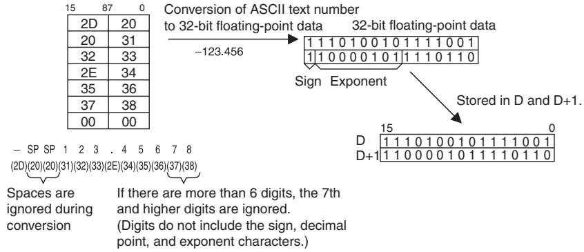
Decimat notation
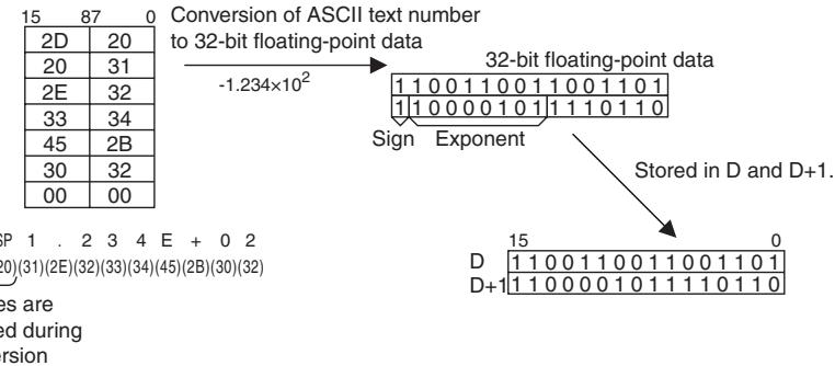
Scientific notation
- Storage of ASCII Text
The following diagrams show how the ASCII text number is converted to floating-point data. Different conversion methods are used for numbers stored with decimal notation and scientific notation.
ASCII Character Storage
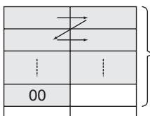
S
FVAL(449) converts the ASCII characters starting with the leftmost byte of S and continuing until a byte containing 00 hex is reached. There must be a byte containing 00 hex within the first 25 bytes.
Up to 00 hex (25 characters max.)
Decimal notation
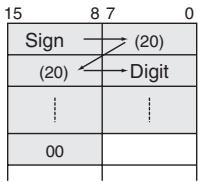
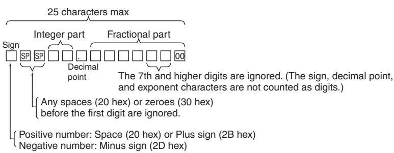
Scientific notation
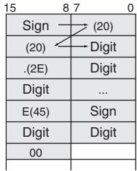
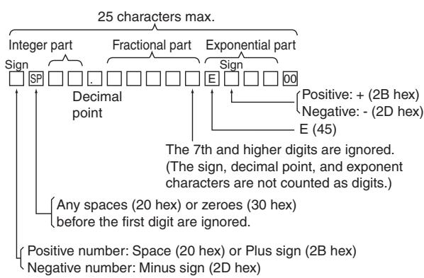
Sample program
- Converting ASCII Text in Decimal Notation to Floating-point Data
When CIO 0.00 is ON in the following example, FVAL(449) converts the specified decimal-notation ASCII text number in the source words starting at D0 to floating-point data and writes the result to destination words D100 and D101.
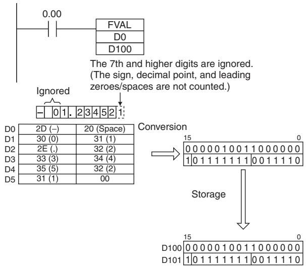
- Converting ASCII Text in Scientific Notation
When CIO 0.00 is ON in the following example, FVAL(449) converts the specified scientific-notation ASCII text number in the source words starting at D0 to floating-point data and writes the result to destination words D100 and D101.
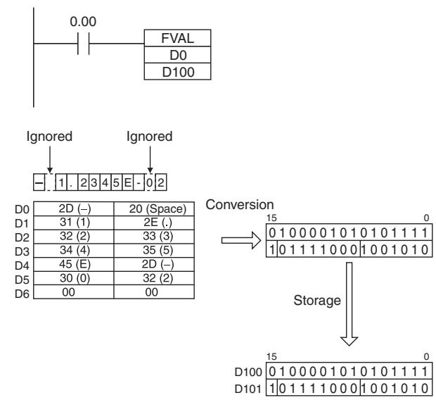
Table Data Processing Instructions
SWAP
| Instruction | Mnemonic | Variations | Function code | Function |
| SWAP BYTES | SWAP | @SWAP | 637 | Switches the leftmost and rightmost bytes in all of the words in the range. |
| Symbol | SWAP |
| SWAP(637) | |
| N | |
| R1 | |
| N: Number of words | |
| R1: First word in range |
Applicable Program Areas
| Area | Step program areas | Subroutines | Interrupt tasks |
| Usage | OK | OK | OK |
Operands
| Operand | Description | Data type | Size |
| N | Number of words | UINT | 1 |
| R1 | First word in range | UINT | Variable |
N: Number of words
N specifies the number of words in the range and must be 0001 to FFFF hexadecimal (or &1 to &65,535).
R1: First word in range
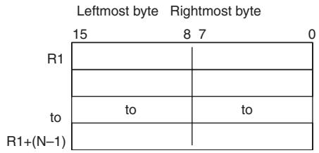
Note R1 and R1 + (N - 1) must be in the same data area.
- Operand Specifications
| Area | Word addresses | Indirect DM addresses | Constants | CF | Pulse bits | TR bits | |||||||
| CIO | WR | HR | AR | T | C | DM | @DM | *DM | |||||
| N | OK | OK | OK | OK | OK | OK | OK | OK | OK | OK | --- | --- | --- |
| R1 | --- | ||||||||||||
Flags
| Name | Label | Operation |
| Error Flag | P_ER | ON if the N is 0. OFF in all other cases. |
Function
SWAP(637) switches the position of the two bytes in all of the words in the range of memory from R1 to R1+N-1.
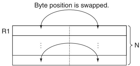
Hint
- This instruction can be used to reverse the order of ASCII-code characters in each word.
Sample program
When CIO 0.00 is ON in the following example, SWAP(637) switches the data in the leftmost bytes with the data in the rightmost bytes in each word in the 10-word range from W0 to W9.
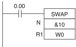
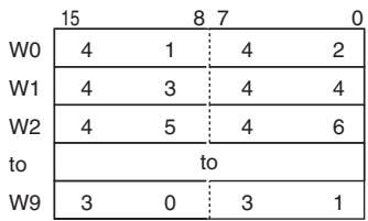

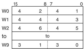
FCS
| Instruction | Mnemonic | Variations | Function code | Function |
| FRAME CHECKSUM | FCS | @FCS | 180 | Calculates the FCS value for the specified range and outputs the result in ASCII. |
| Symbol | FCS | |
| — | — FCS(180) — | ||
| C | C: First control word | |
| R1 | R1: First word in range | |
| D | D: First destination word |
Applicable Program Areas
| Area | Step program areas | Subroutines | Interrupt tasks |
| Usage | OK | OK | OK |
Operands
| Operand | Description | Data type | Size |
| C | First control word | UDINT | 2 |
| R1 | First word in range | UINT | Variable |
| D | First destination word | UINT | Variable |
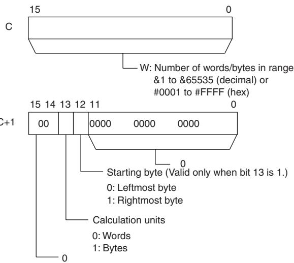
C: First control word
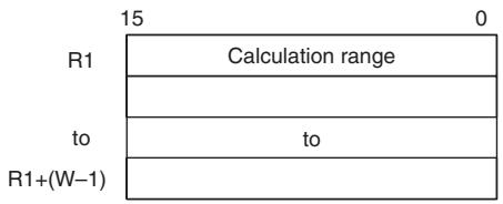
R1: First word in range
D: First destination word
When bytes are specified as the operation units:
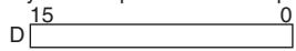
When words are specified as the operation units:
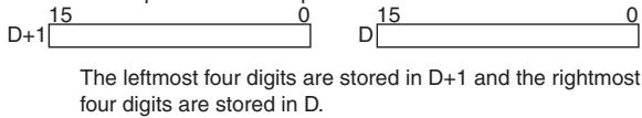
Note C and C + 1 , all of the words in the calculation range must be in the same data area.
- Operand Specifications
| Area | Word addresses | Indirect DM addresses | Constants | CF | Pulse bits | TR bits | |||||||
| CIO | WR | HR | AR | T | C | DM | @DM | *DM | |||||
| C | OK | OK | OK | OK | OK | OK | OK | OK | OK | OK | --- | --- | --- |
| R1, D | --- | ||||||||||||
Flags
| Name | Label | Operation |
| Error Flag | P_ER | ON if the content of C is not within the specified range of 0001 through FFFF.OFF in all other cases. |
Function
FCS(180) calculates the FCS value for W units of data beginning with the data in R1, converts the value to ASCII code, and outputs the result to D (for bytes) or D+1 and D (for words). The settings in C+1 determine whether the units are words or bytes, whether the data is binary (signed or unsigned) or BCD, and whether to start with the right or left byte of R1 if bytes are being added.
When bit 13 of C + 1 has been set to 1, FCS(180) operates on bytes of data. In this case, bit 12 determines whether the calculation starts with the rightmost byte of R1 (bit 12 = 1 ) or the leftmost byte of R1 (bit 12 = 0 ).
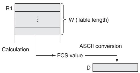
Sample program
When CIO 0.00 is ON in the following example, FCS(180) calculates the FCS value for the 10 bytes of data beginning with the rightmost byte of D100 and writes the result to D200.
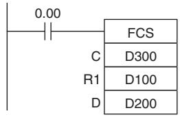
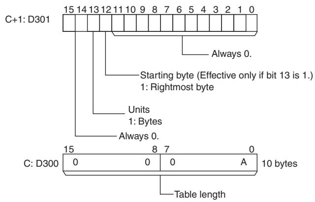
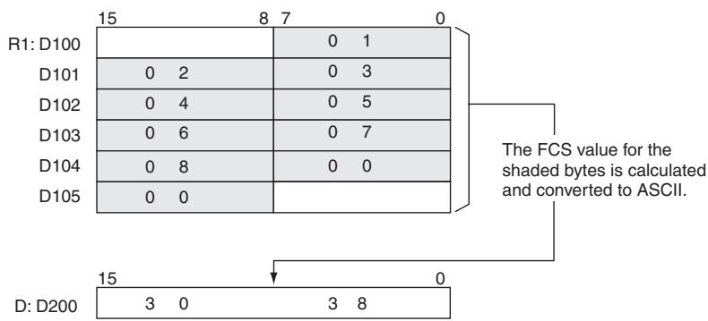
Data Control Instructions
PIDAT
| Instruction | Mnemonic | Variations | Function code | Function |
| PID CONTROL WITH AUTOTUNING | PIDAT | --- | 191 | Executes PID control according to the specified parameters. The PID constants can be autotuned. |
| Symbol | PID | |
| PIDAT(191) | ||
| S | S: Input word | |
| C | C: First parameter word | |
| D | D: Output word | |
Applicable Program Areas
| Area | Step program areas | Subroutines | Interrupt tasks |
| Usage | OK | OK | Not allowed |
Operands
| Operand | Description | Data type | Size |
| S | Input word | UINT | 1 |
| C | First parameter word | WORD | 41 |
| D | Output word | UINT | 1 |
C: First Parameter Word
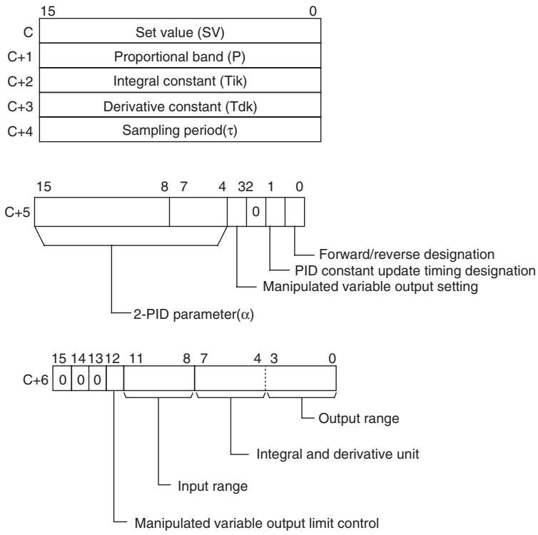
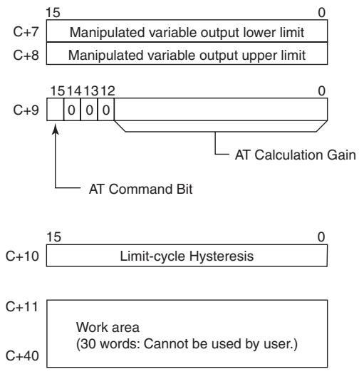
- Operand Specifications
| Area | Word addresses | Indirect DM addresses | Constants | CF | Pulse bits | TR bits | |||||||
| CIO | WR | HR | AR | T | C | DM | @DM | *DM | |||||
| S, C, D | OK | OK | OK | OK | OK | OK | OK | OK | OK | --- | --- | --- | --- |
Flags
| Name | Label | Operation |
| Error Flag | P_ER | ON if the C data is out of range.ON if the actual sampling period is more than twice the designated sampling period.ON if an error occurred during autotuning.OFF in all other cases. |
| Greater Than Flag | P_GT | ON if the manipulated variable after the PID action exceeds the upper limit.OFF in all other cases. |
| Less Than Flag | P_LT | ON if the manipulated variable after the PID action is below the lower limit.OFF in all other cases. |
| Carry Flag | P_CY | ON while PID control is being executed.OFF in all other cases. |
Function
When the execution condition is ON, PIDAT(191) carries out target value filtered PID control with two degrees of freedom according to the parameters designated by C (set value, PID constant, etc.). It takes the specified input range of binary data from the contents of input word S and carries out the PID action according to the parameters that are set. The result is then stored as the manipulated variable in output word D.
The parameter settings are read when the execution condition turns from OFF to ON, and the Error Flag will turn ON if the settings are outside of the permissible range.
If the settings are within the permissible range, PID processing will be executed using the initial values. Bumpless operation is not performed at this time. It will be used for manipulated variables in subsequent PID processing execution. (Bumpless operation is processing that gradually and continuously changes the manipulated variable in order to avoid the adverse effects of sudden changes.)
When the execution condition turns ON, the PV for the specified sampling period is entered and processing is performed.
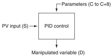
Autotuning
The status of the AT Command Bit (bit 15 of C + 9 ) is checked every cycle. If this control bit is turned ON in a given cycle, PIDAT(191) will begin autotuning the PID constants. (The changes in the SV will not be reflected while autotuning is being performed.)
The limit-cycle method is used for autotuning. PIDAT(191) forcibly changes the manipulated variable (max. manipulated variable min. manipulated variable) and monitors the characteristics of the controlled system. The PID constants are calculated based on the characteristics that were observed, and the new P, I, and D constants are stored automatically in C + 1 , C + 2 , and C + 3 . At this point, the AT Command Bit (bit 15 of C + 9 ) is turned OFF and PID control resumes with the new PID constants in C + 1 , C + 2 , and C + 3 .
- If the AT Command Bit is ON when PIDAT(191) execution begins, autotuning will be performed first and then PID control will start with the calculated PID constants.
- If the AT Command Bit is turned ON during PIDAT(191) execution, PIDAT(191) interrupts the PID control being performed with the user-set PID constants, performs autotuning, and then resumes PID control with the calculated PID constants.
The following flowchart shows the autotuning procedure:
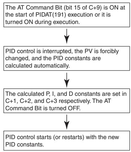
Note 1 If autotuning is interrupted by turning OFF the AT Command Bit during autotuning, PID control will start with the PID constants that were being used before autotuning began.
2 Also, if an AT execution error occurs, PID control will start with the PID constants that were being used before autotuning began.
In both cases described in notes 1 and 2, the PID constants will be enabled if they were already calculated when autotuning was interrupted.
PID Control
- The number of valid input data bits within the 16 bits of the PV input (S) is designated by the input range setting in C + 6 , bits 08 to 11. For example, if 12 bits (4 hex) is designated for the input range, the range from 0000 hex to 0FFF hex will be enabled as the PV. (Values greater than 0FFF hex will be regarded as 0FFF hex.)
- The set value range also depends on the input range.
- Measured values (PV) and set values (SV) are in binary without sign, from 0000 hex to the maximum value of the input range.
- The number of valid output data bits within the 16 bits of the manipulated variable output is designated by the output range setting in C+6, bits 00 to 03. For example, if 12 bits (4 hex) is designated for the output range, the range from 0000 hex to 0FFF hex will be output as the manipulated variable.
- For proportional operation only, the manipulated variable output when the PV equals the SV can be designated as follows:
0: Output 0%
1: Output 50%.
- The direction of proportional operation can be designated as either forward or reverse.
- The upper and lower limits of the manipulated variable output can be designated.
- The sampling period can be designated in units of 10 ms (0.01 to 99.99 s), but the actual PID action is determined by a combination of the sampling period and the time of PIDAT(191) instruction execution (with each cycle).
- The timing of enabling changes made to PID constants can be set to either 1) the beginning of PIDAT(191) instruction execution or 2) the beginning of PID instruction execution and each sampling period. Only the proportional band (P), integral constant (Tik), and derivative constant (Tdk) can be changed each sampling cycle (i.e., during PID instruction execution). The timing is set in bit 1 of C+5.
Hint
- PIDAT(191) is executed as if the execution condition was a STOP-RUN signal. PID calculations are executed when the execution condition remains ON for the next cycle after C + 11 to C + 40 are initialized. Therefore, when using the Always ON Flag (ON) as an execution condition for PIDAT(191), provide a separate process where C + 11 to C + 40 are initialized when operation is started.
Precautions
- A PID parameter storage word cannot be shared by multiple PIDAT instructions. Even when the same parameter is used in multiple PIDAT instructions, separate words must be specified.
- When changing the PID constants manually, set the PID constant change enable setting (bit 1 of C + 5 ) to 1 so that the values in C + 1 , C + 2 , and C + 3 are refreshed each sampling period in the PID calculation. This setting also allows the PID constants to be adjusted manually after autotuning.
-
Of the PID parameters (C to C+40), only the following parameters can be changed when the execution condition is ON. When any other values have been changed, be sure to change the execution condition from OFF to ON to enable the new settings.
-
Set value (SV) in C
(Can be changed during PID control only. An SV change during autotuning will not be reflected.)
- PID constant change enable setting (bit 1 of C+5)
- P, I, and D constants in C+1, C+2, and C+3
(Changes to these constants will be reflected each sampling period only if the PID constant change enable setting (bit 1 of C+5) is set to 1.)
- AT Command Bit (bit 15 of C+9)
- AT Calculation Gain (bits 0 to 14 of C+9) and Limit-cycle Hysteresis (C+10) (These values are read when autotuning starts.)
Performance Specifications
| Item | Specifications | ||
| PID control method | --- | Target value filter-type two-degrees-of-freedom PID method (forward/reverse) | |
| Number of PID control loops | --- | Unlimited (1 loop per instruction) | |
| Sampling period | τ | 0.01 to 99.99 s | |
| PID constant | Proportional band | P | 0.1 to 999.9% |
| Integral constant | Tik | 1 to 8191, 9999 (No integral action for sampling period multiple, 9999.) | |
| Derivative constant | Tdk | 0 to 8191 (No derivative action for sampling period multiple, 0.) | |
| Set value | SV | 0 to 65535 (Valid up to maximum value of input range.) | |
| Measured value | PV | 0 to 65535 (Valid up to maximum value of input range.) | |
| Manipulated variable | MV | 0 to 65535 (Valid up to maximum value of output range.) | |
Calculation Method
Calculations in PID control are performed by the target value filtered control with two degrees of freedom.
Block Diagram for Target Value PID with Two Degrees of Freedom
When overshooting is prevented with simple PID control, stabilization of disturbances is slowed (1). If stabilization of disturbances is speeded up, on the other hand, overshooting occurs and response toward the target value is slowed (2).
When target-value PID control with two degrees of freedom is used, on the other hand, there is no overshooting, and response toward the target value and stabilization of disturbances can both be speeded up (3).
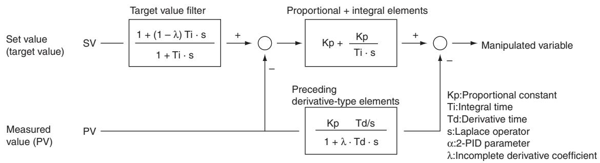
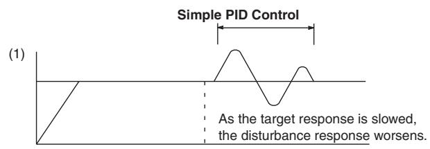
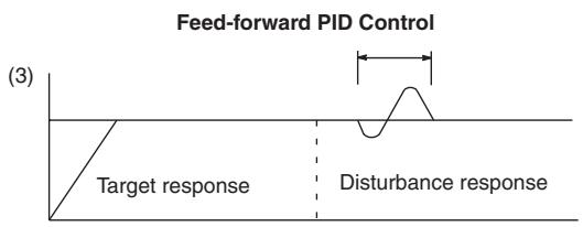
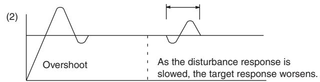
PID Parameter Settings
| Control data | Item | Contents | Setting range | Change with ON input condition |
| C | Set value (SV) | The target value of the process being controlled. | Binary data (of the same number of bits as specified for the input range) | Allowed |
| C+1 | Proportional band | The parameter for P action expressing the proportional control range/total control range. | 0001 to 270F hex (1 to 9999); (0.1% to 999.9%, in units of 0.1%) | Can be changed with input condi-tion ON if bit 1 of C+5 is 1. |
| C+2 | Tik Integral Constant | A constant expressing the strength of the integral action. As this value increases, the integral strength decreases. | 0001 to 1FFF hex (1 to 8191); (9999 = Integral operation not executed) (See note 1.) | |
| C+3 | Tdk Derivative Constant | A constant expressing the strength of the deriva-tive action. As this value increases, the derivative strength decreases. | 0001 to 1FFF hex (1 to 8191); (0000 = Derivative operation not executed) (See note 1.) | |
| C+4 | Sampling period (τ) | Sets the period for executing the PID action. | 0001 to 270F hex (1 to 9999); (0.01 to 99.99 s, in units of 10 ms) | Not allowed |
| Bits 04 to 15 of C+5 | 2-PID parameter (α) | The input filter coefficient. Normally use 0.65 (i.e., a setting of 000). The filter efficiency decreases as the coefficient approaches 0. | 000 hex: α = 0.65 Setting from 100 to 163 hex means that the value of the rightmost two digits is set from α= 0.00 to α= 0.99. (See note 2.) | |
| Bit 03 of C+5 | Manipulated variable output designation | Designates the manipulated variable output for when the PV equals the SV. | 0: Output 0%1: Output 50% | |
| Bit 01 of C+5 | PID constant change enable setting | The timing of enabling changes made to the pro-porportional band (P), integral constant (Tik), and derivative constant (Tdk) for use in PID calcula-tions. | 0: At start of PID instruction execution1: At start of PID instruction execution and each sampling period | Allowed |
| Bit 00 of C+5 | PID forward/reverse designation | Determines the direction of the proportional action. | 0: Reverse action1: Forward action | Not allowed |
| Bit 12 of C+6 | Manipulated variable output limit control | Determines whether or not limit control will apply to the manipulated variable output. | 0: Disabled (no limit control)1: Enabled (limit control) | |
| Bits 08 to 11 of C+6 | Input range | The number of input data bits. | 0: 8 bits 5: 13 bits1: 9 bits 6: 14 bits2: 10 bits 7: 15 bits3: 11 bits 8: 16 bits4: 12 bits | |
| Bits 04 to 07 of C+6 | Integral and deriva-tive unit | Determines the unit for expressing the integral and derivative constants. | 1: Sampling period multiple9: Time (unit: 100 ms) | |
| Bits 00 to 03 of C+6 | Output range | The number of output data bits. (The number of output bits is automatically the same as the num-ber of input bits.) | 0: 8 bits 5: 13 bits1: 9 bits 6: 14 bits2: 10 bits 7: 15 bits3: 11 bits 8: 16 bits4: 12 bits | |
| C+7 | Manipulated variable output lower limit | The lower limit for when the manipulated variable output limit is enabled. | 0000 to FFFF (binary)(See note 3.) | |
| C+8 | Manipulated variable output upper limit | The upper limit for when the manipulated variable output limit is enabled. | 0000 to FFFF (binary)(See note 3.) | |
| Bit 15 of C+9 | AT Command Bit | This control bit starts autotuning.• Set the AT Command Bit to 1 to perform auto-tuning. (Autotuning can be started while PIDAT(191) is being executed.)• This bit is turned OFF automatically when auto-tuning is completed.Autotuning will be interrupted if the AT Command Bit is turned OFF manually. In this case, the PID constants will be enabled if they were already cal-culated when autotuning was interrupted. | As a Control Bit:0→1:Executes autotuning.1→0:Interrupts autotuning.(PID(191) turns the bit OFF automatically when autotuning is completed.As a Flag:0: Autotuning is not being executed.1: Autotuning is being executed. | Allowed |
| Bits 00 to 11 of C+9 | AT Calculation Gain | Set this parameter to adjust the contribution of the PID calculation results to the stored values.Normally, leave this parameter set to its default(0000).• Increase the value when emphasizing stability.Decrease the value when emphasizing respon-siveness. | 0000 hex: 1.00 (Default)0001 to 03E8 hex (1 to 1000); (0.01 to 10.00, in units of 0.01) | Allowed(These parameters are read when autotuning starts.) |
| C+10 | Limit-cycle Hysteresis | Sets the hysteresis when the limit cycle is gener-ated. The default setting for reverse operation turns ON the MV with a hysteresis of SV-20%.Increase this setting if a proper limit cycle cannot be generated because the PV is unstable. How-ever, the AT accuracy will decline if the Limit-cycle Hysteresis is higher than necessary. | 0000 hex: 0.20% (Default)0001 to 03E8 hex:0.01 to 10.00% in units of 0.01%FFFF hex: 0.00%Note The percentage is with respect to the input range. |
Note 1 When the unit is designated as 1, the range is from 1 to 8,191 times the period. When the unit is designated as 9, the range is from 0.1 to 819.1 s. When 9 is designated, set the integral and derivative times to within a range of 1 to 8,191 times the sampling period.
2 Setting the 2-PID parameter () to 000 yields 0.65, the normal value.
3 When the manipulated variable output limit control is enabled (i.e., set to "1"), set the values as follows: 0000 ≤ MV output lower limit ≤ MV output upper limit ≤ Max. value of output range
Sampling Period and Cycle Time
The sampling period can be designated in units of 10 ms (0.01 to 99.99 s), but the actual PID action is determined by a combination of the sampling period and the time of PID instruction execution (with each cycle). The relationship between the sampling period and the cycle time is as follows:
- If the sampling period is less than the cycle time, PID control is executed with each cycle and not with each sampling period.
- If the sampling period is greater than or equal to the cycle time, PID control is not executed with each cycle, but PID(190) is executed when the cumulative value of the cycle time (the time between PID instructions) is greater than or equal to the sampling period. The surplus portion of the cumulative value (i.e., the cycle time's cumulative value minus the sampling period) is carried forward to the next cumulative value.
For example, suppose that the sampling period is 100 ms and that the cycle time is consistently 60 ms. For the first cycle after the initial execution, PID(190) will not be executed because 60 ms is less than 100 ms. For the second cycle, 60 ms + 60 ms is greater than 100 ms, so PID(190) will be executed. The surplus of 20 ms (i.e., 120 ms - 100 ms = 20 ms) will be carried forward.
For the third cycle, the surplus 20ms is added to 60~ms . Because the sum of 80~ms is less than 100 ms, PID(190) will not be executed. For the fourth cycle, the 80~ms is added to 60~ms . Because the sum of 140~ms is greater than 100~ms , PID(190) will be executed and the surplus of 40~ms (i.e., 120~ms - 100~ms = 20~ms ) will be carried forward. This procedure is repeated for subsequent cycles.
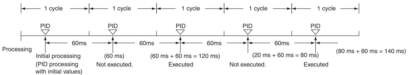
Reading of measurement time
Less than 100 ms, so PID is not executed.
Greater than 100 ms, so PID is executed and 20 ms is carried forward.
Less than 100 ms, so PID is not executed.
Greater than 100 ms, so PID is executed and 40 ms is carried forward.
PID control
Proportional Action (P)
Proportional action is an operation in which a proportional band is established with respect to the set value (SV), and within that band the manipulated variable (MV) is made proportional to the deviation. An example for reverse operation is shown in the following illustration.
If the proportional action is used and the present value (PV) becomes smaller than the proportional band, the manipulated variable (MV) is 100% (i.e., the maximum value). Within the proportional band, the MV is made proportional to the deviation (the difference between from SV and PV) and gradually decreased until the SV and PV match (i.e., until the deviation is 0), at which time the MV will be at the minimum value of 0% (or 50% , depending on the setting of the manipulated variable output designation parameter). The MV will also be 0% when the PV is larger than the SV.
The proportional band is expressed as a percentage of the total input range. The smaller the proportional band, the larger the proportional constant and the stronger the corrective action will be. With proportional action an offset (residual deviation) generally occurs, but the offset can be reduced by making the proportional band smaller. If it is made too small, however, hunting will occur.
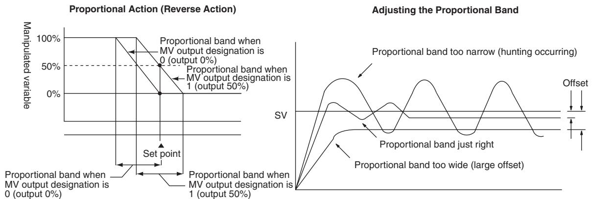
- Integral Action (I)
Combining integral action with proportional action reduces the offset according to the time that has passed, so that the PV will match the SV. The strength of the integral action is indicated by the integral time, which is the time required for the manipulated variable of the integral action to reach the same level as the manipulated variable of the proportional action with respect to the step deviation, as shown in the following illustration. The shorter the integral time, the stronger the correction by the integral action will be. If the integral time is too short, the correction will be too strong and will cause hunting to occur.
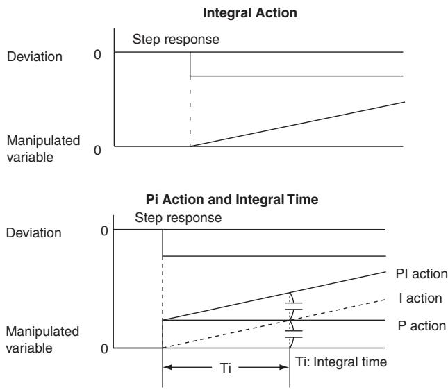
- Derivative Action (D)
Proportional action and integral action both make corrections with respect to the control results, so there is inevitably a response delay. Derivative action compensates for that drawback. In response to a sudden disturbance it delivers a large manipulated variable and rapidly restores the original status. A correction is executed with the manipulated variable made proportional to the incline (derivative coefficient) caused by the deviation.
The strength of the derivative action is indicated by the derivative time, which is the time required for the manipulated variable of the derivative action to reach the same level as the manipulated variable of the proportional action with respect to the step deviation, as shown in the following illustration. The longer the derivative time, the stronger the correction by the derivative action will be.
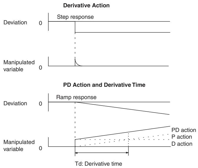
PID Action
PID action combines proportional action (P), integral action (I), and derivative action (D). It produces superior control results even for control objects with dead time. It employs proportional action to provide smooth control without hunting, integral action to automatically correct any offset, and derivative action to speed up the response to disturbances.

Direction of Action
When using PID control, select either of the following two control directions. In either direction, the MV increases as the difference between the SV and the PV increases.
- Forward action: MV is increased when the PV is larger than the SV.
- Reverse action: MV is increased when the PV is smaller than the SV.
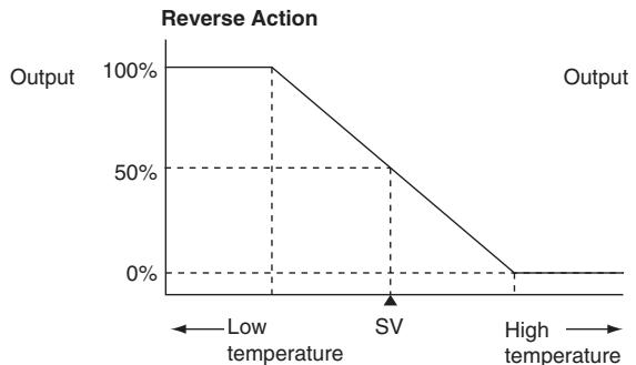
(MV output designation: 50%
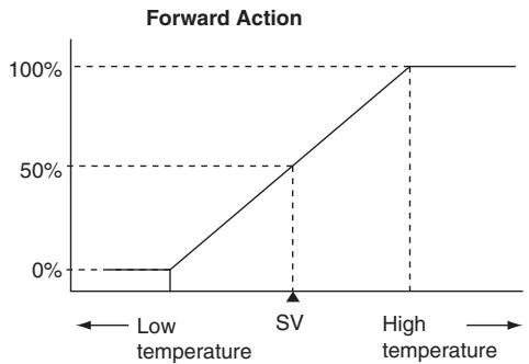
Adjusting PID Parameters
The general relationship between PID parameters and control status is shown below.
- When it is not a problem if a certain amount of time is required for stabilization (settlement time), but it is important not to cause overshooting, then enlarge the proportional band.
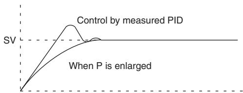
- When there is broad hunting, or when operation is tied up by overshooting and undershooting, it is probably because integral action is too strong. The hunting will be reduced if the integral time is increased or the proportional band is enlarged.
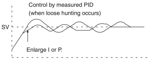
- When overshooting is not a problem but it is desirable to quickly stabilize control, then narrow the proportional band. If the proportional band is narrowed too much, however, then hunting may occur.
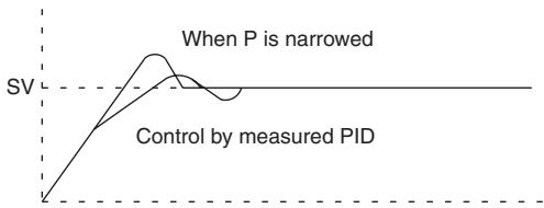
- If the period is short and hunting occurs, it may be that the control system response is quick and the derivative action is too strong. In that case, set the derivative action lower.
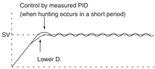
Sample program
- Interrupting PID Control to Perform Autotuning
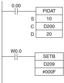
- At the rising edge of CIO 0.00 (OFF to ON), the work area in D211 to D240 is initialized according to the parameters (shown below) set in D200 to D208. After the work area has been initialized, PID control is executed and the manipulated variable is output to CIO 20.
- While CIO 0.00 is ON, PID control is executed at the sampling period intervals according to the parameters set in D200 to D210. The manipulated variable is output to CIO 20.
- The PID constants used in PID calculations will not be changed even if the proportional band (P), integral constant (Tik), or derivative constant is changed after CIO 0.00 turns ON.
- At the rising edge of W 0.0 (OFF to ON), SETB(532) turns ON bit 15 of D209 ( C + 9 ) and starts autotuning. When autotuning is completed, the calculated P , I , and D constants are written to C + 1 , C + 2 , and C + 3 . PID control is then restarted with the new PID constants.
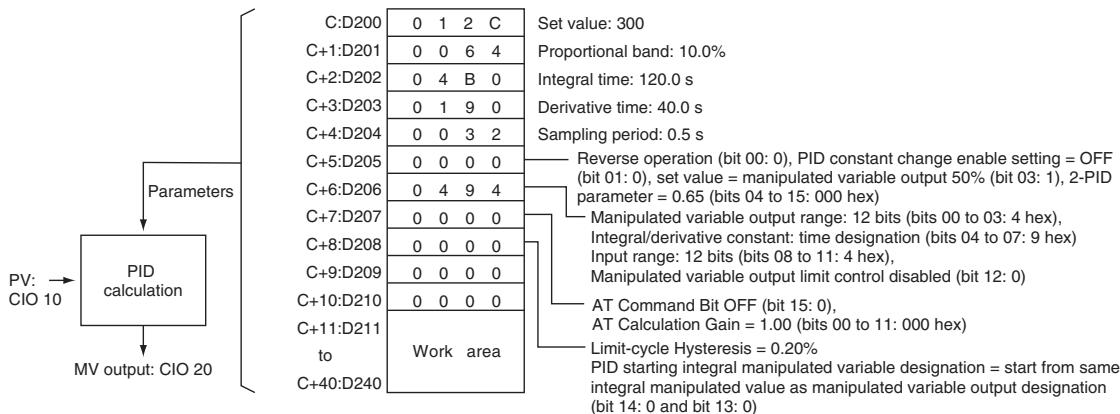
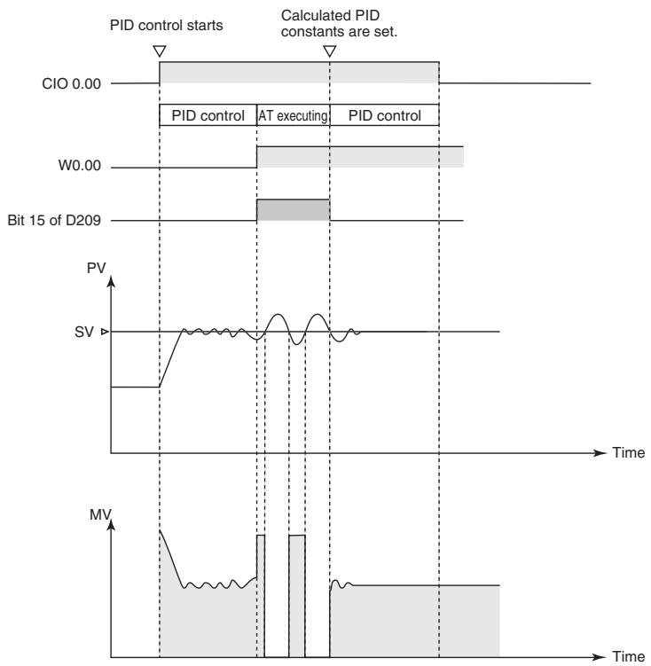
- Starting PIDAT(191) with Autotuning
| 0.00 | |
| PIDAT | |
| S | 10 |
| C | D200 |
| D | 20 |
At the rising edge of CIO 0.00 (OFF to ON), autotuning will be performed first if bit 15 of D209 (C + 9) is ON. When autotuning is completed, the calculated P, I, and D constants are written to C + 1 , C + 2 , and C + 3 . PID control is then started with the calculated PID constants.
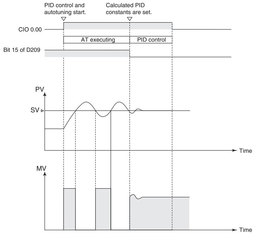
- Interrupting Autotuning Before Completion
Autotuning can be interrupted by turning bit 15 of D209 (C+9) from ON to OFF. PID control will be restarted with the P, I, and D constants that were in effect before autotuning was started.
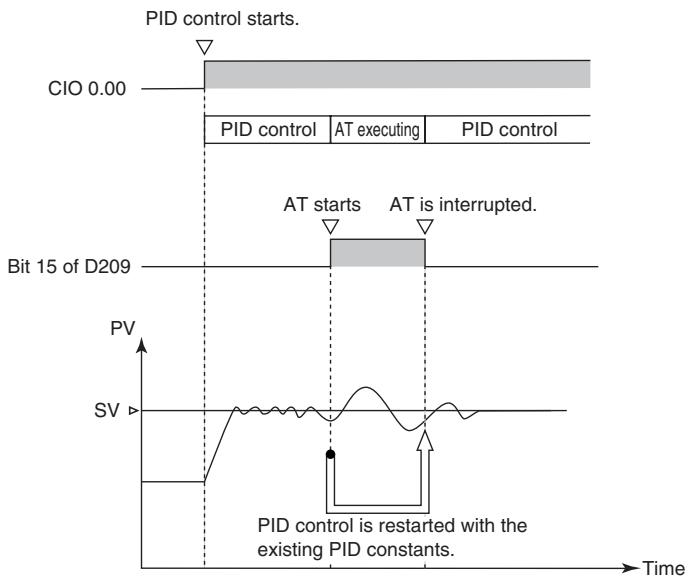
TPO
| Instruction | Mnemonic | Variations | Function code | Function |
| TIME-PROPORTIONAL OUTPUT | TPO | --- | 685 | Inputs the duty ratio or manipulated variable from the specified word, converts the duty ratio to a time-proportional output based on the specified parameters, and outputs the result from the speci-fied output. |
| Symbol | TPO | |
| TPO | S: Input word C: First parameter word R: Pulse output bit | |
| S | ||
| C | ||
| R | ||
Applicable Program Areas
| Area | Step program areas | Subroutines | Interrupt tasks |
| Usage | OK | OK | OK |
Operands
| Operand | Description | Data type | Size |
| S | Input word | UINT | 1 |
| C | First parameter word | WORD | 7 |
| R | Pulse output bit | BOOL | --- |
S: Input Word
Specifies the input word containing the input duty ratio or manipulated variable.
- Input duty ratio: 0000 to 2710 hex (0.00% to 100.00%)
- Input manipulated variable (See note.): 0000 to FFFF hex (0 to 65,535 max.) (Bits 00 to 03 of C specify the manipulated variable range, i.e., the number of valid bits in the manipulated variable. Specify the same number of bits as specified for the output range setting in PIDAT(191).)
Note If S is a manipulated variable, specify the word containing the manipulated variable output from a PIDAT(191) instruction.
C: First Parameter Word
Bits 04 to 07 of C specify the input type, i.e., whether the input word contains an input duty ratio or manipulated variable. (Set these bits to 0 hex to specify a input duty ratio or to 1 hex to specify a manipulated variable.)
The following diagram shows the locations of the parameter data.
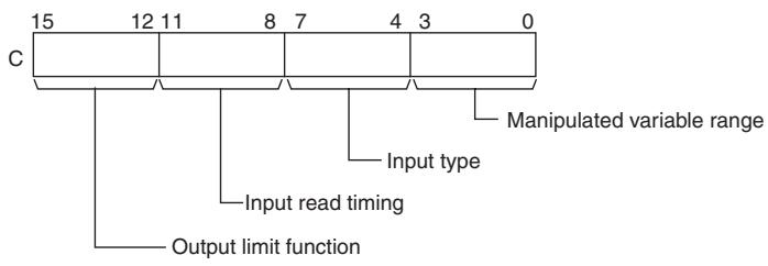
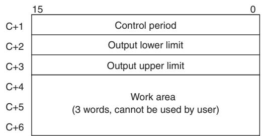
Note For details, see the description of each parameter.
R: Pulse Output Bit
Specifies the destination output bit for the pulse output.
Normally, specify an output bit allocated to a Transistor Output Unit and connect a solid state relay to the Transistor Output Unit.
- Operand Specifications
| Area | Word addresses | Indirect DM addresses | Constants | CF | Pulse bits | TR bits | |||||||
| CIO | WR | HR | AR | T | C | DM | @DM | *DM | |||||
| S | OK | OK | OK | OK | OK | OK | OK | OK | OK | OK | --- | --- | --- |
| C | --- | ||||||||||||
| R | --- | --- | --- | --- | --- | ||||||||
Flags
| Name | Label | Operation |
| Error Flag | ER | ON if the input data in S is out of range. (The input data setting range depends on the input type setting.)ON if the C data is out of range. (The manipulated variable range will cause an error only when the input type is set to manipulated variable.)ON if the control period in C+1 is out of range.ON if the output limit function is enabled but the output lower limit (C+2) or output upper limit (C+3) is out of range.ON if the output limit function is enabled but the output lower limit (C+2) is less than or equal to the output upper limit (C+3).OFF in all other cases. |
Function
Receives a duty ratio or manipulated variable input from the word address specified by S, converts the duty ratio to a time-proportional output (see note) based on the parameters specified in words C to C+3, and outputs a pulse output to the bit specified by R.
Note A time-proportional output is changed proportionally based on the ON/OFF ratio in input word S. The period in which the ON and OFF status changes is known as the control period and is set in parameter word C+1. Example: When the control period is 1 s and the input value is 50% , the bit is ON for 0.5 s and OFF for 0.5 s. When the control period is 1 s and the input value is 80% , the bit is ON for 0.8 s and OFF for 0.2 s.
Generally, TPO(685) is used together with PIDAT(191) and the PID instruction's manipulated variable result word (D) is specified as the input word (S) for the TPO(685) instruction. Also, an output bit allocated to a Transistor Output Unit is generally specified as R and a solid state relay is connected to the Transistor Output Unit to perform time-proportional control of a heater (proportional control of the ON/OFF ratio).
- Combining TPO(685) with a PID Control Instruction
When combining TPO(685) with a PID control instruction, the manipulated variable input is divided by the manipulated variable range to calculate the duty ratio, that duty ratio is converted to a time-proportional output, and pulses are output.
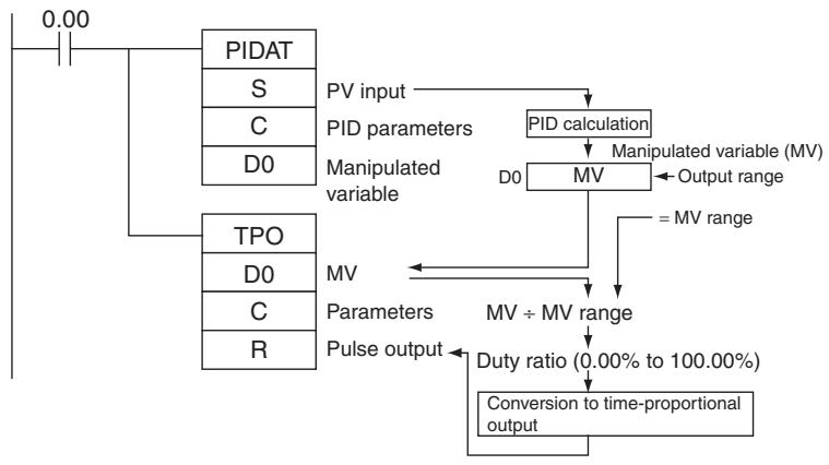
In this case, set the same value for the PID Control instruction's output range and the TPO(685) instruction's manipulated variable range. For example, when the PID Control instruction's output range and the TPO(685) instruction's manipulated variable range are both set to 12 bits (0000 to 0FFF hex), the duty ratio is calculated by dividing the manipulated variable from the PID Control instruction by 0FFF hex and TPO(685) converts that duty ratio to a time-proportional output.
- External Wiring Example
Connect the Transistor Output Unit to a solid state relay (SSR) as shown in the following diagram.
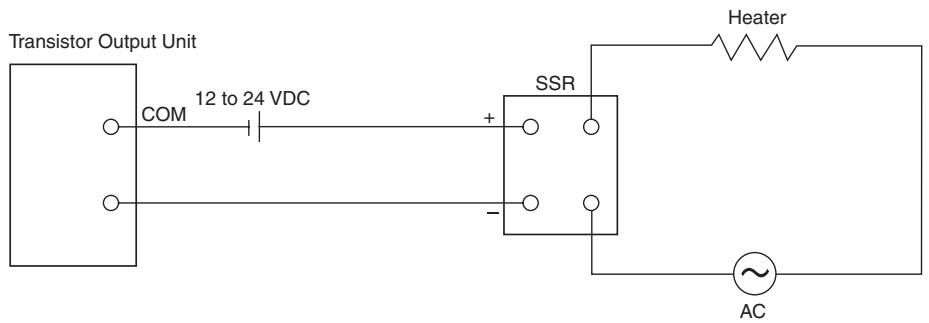
Parameter Settings
| Control data | Item | Contents | Setting range | Change with ON input condition | |
| Word | Bits | ||||
| C | 00 to 03 | Manipulated variable range | Specifies the number of input data bits. | 0 hex: 8 bits 5 hex: 13 bits1 hex: 9 bits 6 hex: 14 bits2 hex: 10 bits 7 hex: 15 bits3 hex: 11 bits 8 hex: 16 bits4 hex: 12 bits | Allowed |
| 04 to 07 | Input type | Specifies whether S contains a duty ratio or manipulated variable. | 0 hex: Duty ratioSetting range for S: 0000 to 2710 hex (0.00 to 100.00%)1 hex: Manipulated variableSetting range for S: 0000 to FFFF hex (0 to 65,535)(The maximum setting depends on the MV range set with bits 00 to 03 of C.) | Allowed | |
| 08 to 11 | Input read timing | Specifies the input read timing. | 0 hex: Use the beginning value of the control period1 hex: Use lower value2 hex: Use higher value3 hex: Continuous adjustment | Allowed | |
| 12 to 15 | Output limit control | Specifies whether the output limit function is enabled or disabled. | 0 hex: Disabled1 hex: Enabled (See note.) | Allowed | |
| C+1 | 00 to 15 | Control period | Control period(Time period in which the ON/OFF changes are made.) | 0064 to 270F hex (1.00 to 99.99 s)Note For example, 1.00 s is set as 0064 hex, and not 0001 hex. | Allowed |
| C +2 | 00 to 15 | Output lower limit | Specifies the lower limit when the output limit is enabled. | 0000 to 2710 hex (0 to 100.00%) | Allowed |
| C +3 | 00 to 15 | Output upper limit | Specifies the upper limit when the output limit is enabled. | 0000 to 2710 hex (0 to 100.00%) | Allowed |
| C+4 | 00 to 15 | Work area | This work area is used by the system. It cannot be used by the user. | Cannot be used. | --- |
| C+5 | 00 to 15 | ||||
| C+6 | 00 to 15 | ||||
Note When the output limit control function is enabled, set the lower and upper limits as follows: 0000 hex ≤ lower limit ≤ upper limit ≤ 2710 hex.
Execution
- The instruction is executed while the input condition is ON.
-
When instruction execution starts, the output bit (R) is turned ON/OFF according to the duty ratio.
-
The parameters (in C to C+3) are read in real time each time that the instruction is executed. When changing the parameters, change all of them at the same time so that different sets of parameters are not mixed.
- The output (R) is turned ON/OFF when the instruction is executed and the accuracy of the output's ON/OFF timing is 10 ms max.
- Execution of the instruction stops when the input condition goes OFF. At that time, the elapsed time value will be reset and the control period will be initialized.
- The input type setting (bits 04 to 07 of C) determines whether the input word (S) contains a duty ratio or manipulated variable. When S contains the manipulated variable, the duty ratio is calculated by dividing the manipulated variable input by the manipulated variable range (bits 00 to 03 of C).
- The input read timing setting (bits 08 to 11 of C) specifies when the input word (S) is read, as shown in the following table:
| Input read timing | Description |
| 0: Use the beginning value of the control period | The duty ratio input is read at the beginning of the control period and the ratio cannot be changed during the control period. |
| 1: Use lower value | If the duty ratio input falls below the duty ratio at the beginning of the control period, the lower value will take precedence and the output ON time will be reduced accordingly. |
| 2: Use higher value | If the duty ratio input rises above the duty ratio at the beginning of the control period, the higher value will take precedence and the output ON time will be increased accordingly. |
| 3: Continuous adjustment | The duty ratio will be read in real time each time the instruction is executed and the ON/OFF operation will be repeated within the control period. |
The following diagrams show the operation of each input read timing setting.
- Input time setting = 0 (Use the beginning value of the control period.)
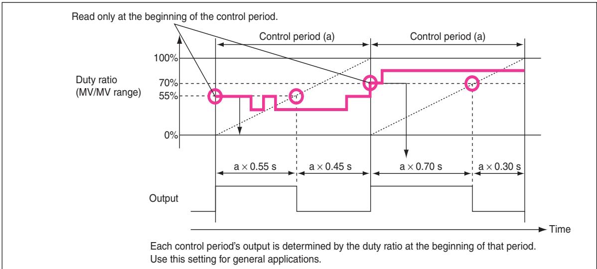
- Input time setting = 1 (Use lower value.)
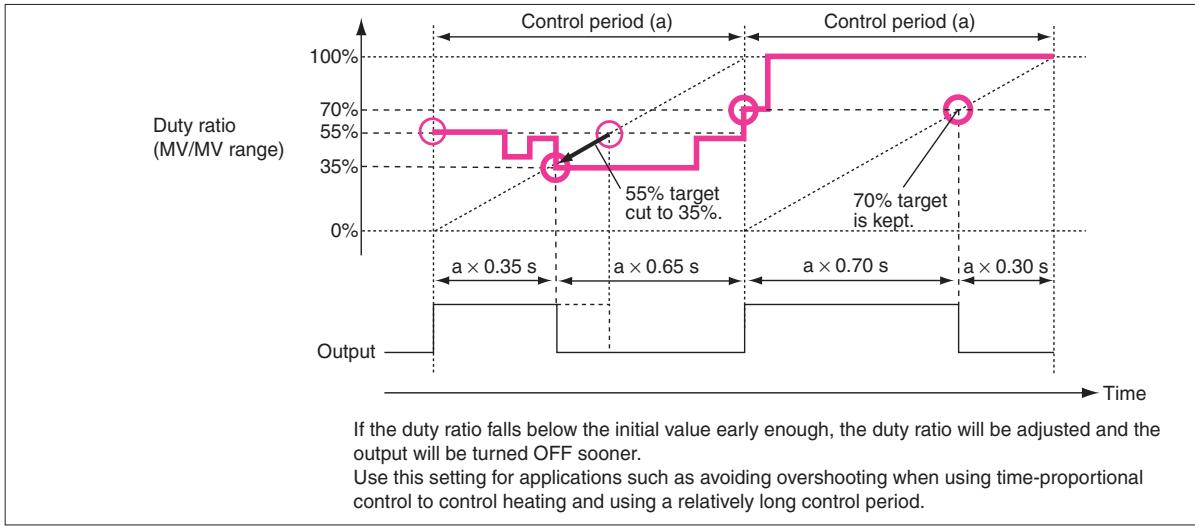
- Input time setting = 2 (Use higher value.)
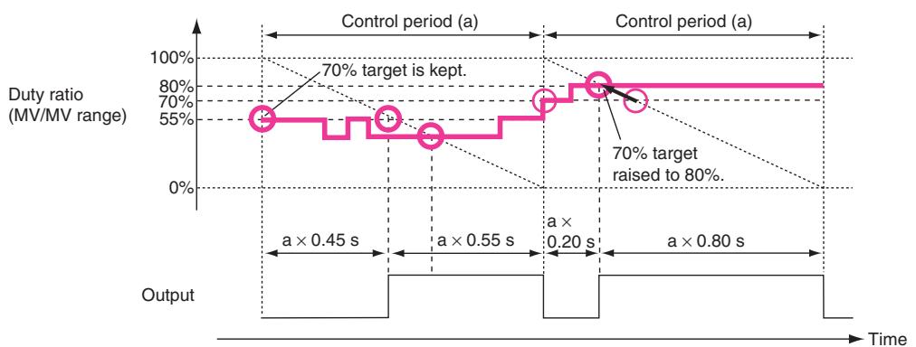
If the duty ratio rises above the initial value early enough, the duty ratio will be adjusted and the output will be turned ON sooner. (With this setting the output's ON/OFF order is reversed and the output goes from OFF to ON.)
Use this setting for applications such as avoiding undershooting when using time-proportional control to control cooling and using relatively long control period.
- Input time setting = 3 (Continuous adjustment)
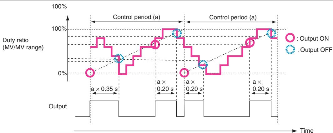
Changes in the duty ratio are monitored in real time. If the duty ratio falls below the initial value early enough, the duty ratio will be adjusted and the output will be turned OFF sooner. If the duty ratio rises again after that, the ratio will be adjusted again and the output will be turned ON. This process is repeated continuously. Use this setting to improve responsiveness when the control period is relatively long and the duty ratio changes quickly. This setting is also appropriate for lighting or power applications that require precise control.
- The output limiter function (bits 12 to 15 of C) can be enabled to restrict (saturate) output when it is outside the range between the output limiter lower limit (C + 2) and output limiter upper limit (C + 3) .
Precautions
When using TPO(685) in combination with PIDAT(191) in a cyclic task and also using an interrupt task, temporarily disable interrupts by executing DI(693) (DISABLE INTERRUPTS) ahead PIDAT(191) and TPO(685). If interrupts are not disabled and an interrupt occurs between the PIDAT(191) and TPO(685), the control period may be shifted.
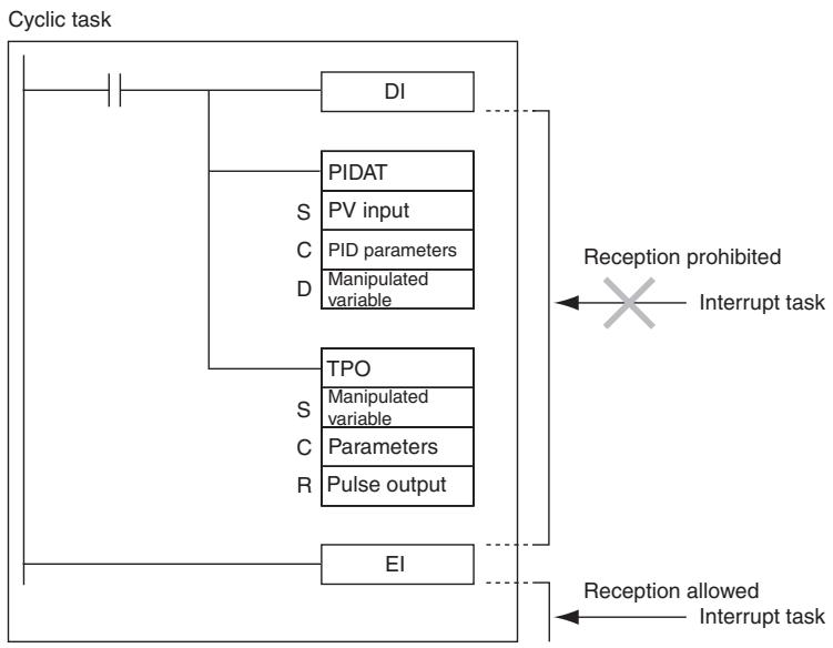
Sample program
Combining TPO(685) with PIDAT(191)
When CIO 0.00 is ON, TPO(685) takes the manipulated variable output from PIDAT(191) (contained in D0), calculates the duty ratio from that manipulated variable value (Duty ratio = MV ÷ MV range), converts the duty ratio to a time-proportional output, and outputs the pulses to bit 01 of CIO 100.
In this case, CIO 100 is allocated to a Transistor Output Unit and bit CIO 100.01 is connected to a solid state relay for heater control.
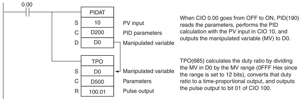
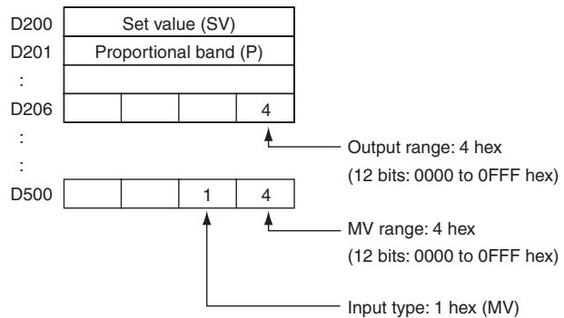
Using TPO(685) Alone
When CIO 0.00 is ON, TPO(685) takes the duty ratio in D10, converts the duty ratio to a time-proportional output, and outputs the pulses to bit 00 of CIO 100.
In this case, the control period is 1 s and the output limit function is enabled with a lower limit 20.00% and an upper limit of 80.00% .
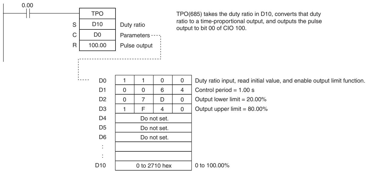
SCL
| Instruction | Mnemonic | Variations | Function code | Function |
| SCALING | SCL | @SCL | 194 | Converts unsigned binary data into unsigned BCD data according to the specified linear function. |
| Symbol | SCL | |
| SCL(194) | S: Source word | |
| S | P1: First parameter word | |
| R | R: Result word | |
Applicable Program Areas
| Area | Step program areas | Subroutines | Interrupt tasks |
| Usage | OK | OK | OK |
Operands
| Operand | Description | Data type | Size |
| S | Source word | UINT | 1 |
| P1 | First parameter word | LWORD | 4 |
| R | Result word | WORD | 1 |
P1: First Parameter Word
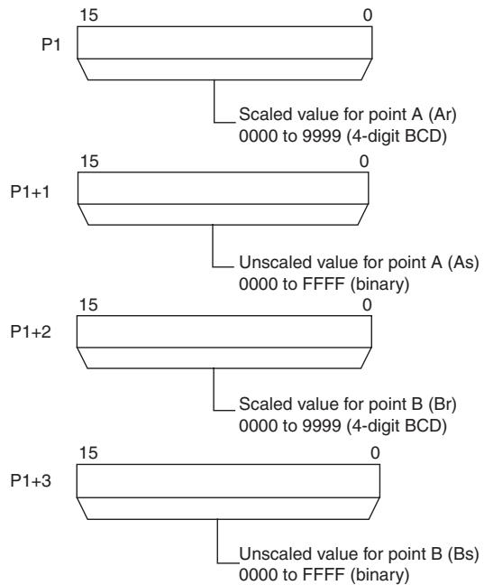
Note P1 to P1 + 3 must be in the same area.
- Operand Specifications
| Area | Word addresses | Indirect DM addresses | Constants | CF | Pulse bits | TR bits | |||||||
| CIO | WR | HR | AR | T | C | DM | @DM | *DM | |||||
| S, P1, R | OK | OK | OK | OK | OK | OK | OK | OK | OK | --- | --- | --- | --- |
Flags
| Name | Label | Operation |
| Error Flag | P_ER | ON if the contents of P1 (Ar) or P1+1 (Br) is not BCD. ON if the contents of P1+1 (As) and P1+3 (Bs) are equal. OFF in all other cases. |
| Equals Flag | P_EQ | ON if the result is 0. OFF in all other cases. |
Function
SCL(194) is used to convert the unsigned binary data contained in the source word S into unsigned BCD data and place the result in the result word R according to the linear function defined by points (As, Ar) and (Bs, Br). The address of the first word containing the coordinates of points (As, Ar) and (Bs, Br) is specified for the first parameter word P1. These points define by 2 values (As and Bs) before scaling and 2 values (Ar and Br) after scaling.
The following equations are used for the conversion.
$$ R = B d - \frac {(B r - A r)}{B C D c o n v e r s i o n o f (B s - A s)} \times B C D c o n v e r s i o n o f (B s - S) $$
Points A and B can define a line with either a positive or negative slope. Using a negative slope enables reverse scaling.
- The result will be rounded to the nearest integer. If the result is less than 0000, 0000 will be output as the result.
- If the result is greater than 9999, 9999 will be output.
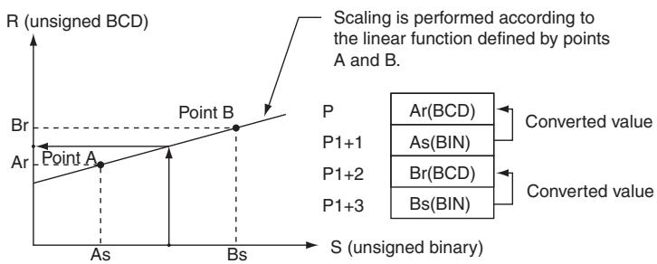
Hint
- SCL(194) can be used to scale the results of analog signal conversion values from Analog Input Units according to user-defined scale parameters. For example, if a 1 to 5-V input to an Analog Input Unit is input to memory as 0000 to 0FA0 hexadecimal, the value in memory can be scaled to 50 to 200^ using SCL(194).
- SCL(194) converts unsigned binary to unsigned BCD. To convert a negative value, it will be necessary to first add the maximum negative value in the program before using SCL(194) (see example). SCL(194) cannot output a negative value to the result word, R. If the result is a negative value, 0000 will be output to R.
Sample program
In the following example, it is assumed that an analog signal from 1 to 5V is converted and input to D0 as 0000 to 0FA0 hexadecimal. SCL(194) is used to convert (scale) the value in CIO 200 to a value between 0 and 300 BCD.
When CIO 0.00 is ON, the contents of D0 is scaled using the linear function defined by point A (0000, 0000) and point B (0FA0, 0300). The coordinates of these points are contained in D100 to D103, and the result is output to D200.
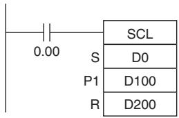
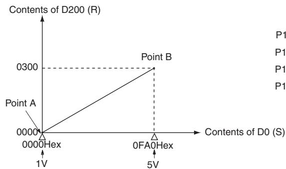
| P1: D100 | 0 | 0 | 0 | 0 | Ar(BCD) |
| P1+1:D101 | 0 | 0 | 0 | 0 | As(BIN) |
| P1+2:D102 | 0 | 3 | 0 | 0 | Br(BCD) |
| P1+3:D103 | 0 | F | A | 0 | Bs(BIN) |
Reference:
An Analog Input Unit actually inputs values from FF38 to 1068 hexadecimal for 0.8 to 5.2 V. SCL(194), however, can handle only unsigned binary values between 0000 and FFFF hexadecimal, making it impossible to use SCL(194) directly to handle signed binary values below 1 V (0000 hexadecimal), i.e., FF38 to FFFF hexadecimal. In an actual application, it is thus necessary to add 00C8 hexadecimal to all values so that FF38 hexadecimal is represented as 0000 hexadecimal before using SCL(194), as shown in the following example.
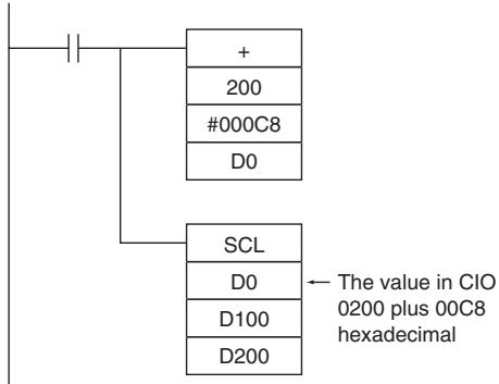

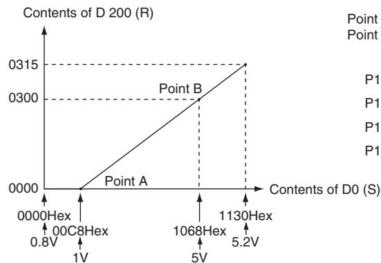
Point A (00C8 Hex 0000 (BCD)) Point B (1068 Hex 0300 (BCD))
| P1: D100 | 0 | 0 | 0 | 0 |
| P1+1:D101 | 0 | 0 | C | 8 |
| P1+2:D102 | 0 | 3 | 0 | 0 |
| P1+3:D103 | 1 | 0 | 6 | 8 |
In this example, values from 0000 to 00C8 hexadecimal will be converted to negative values. SCL(194), however, can output only unsigned BCD values from 0000 to 9999, so 0000 BCD will be output whenever the contents of D0.00 is between 0000 and 00C8 hexadecimal.
Reverse Scaling
Reverse scaling can also be used by setting As < Bs and Ar > Br . The following relationship will result.
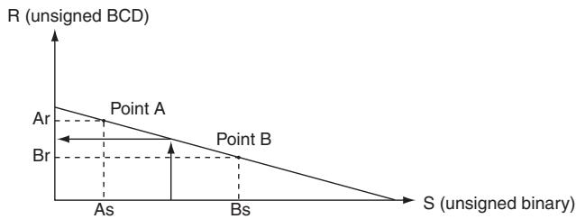
Reverse scaling can be used, for example, to convert (reverse scale) 1 to 5V (0000 to 0FA0 hexadecimal) to 0300 to 0000, respectively, as shown in the following diagram.
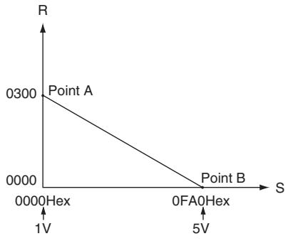
SCL2
| Instruction | Mnemonic | Variations | Function code | Function |
| SCALING 2 | SCL2 | @SCL2 | 486 | Converts signed binary data into signed BCD data according to the specified linear function. An offset can be input in defining the linear function. |
| Symbol | SCL2 | |
| SCL2(486) | S: Source word | |
| S | P1: First parameter word | |
| R | R: Result word | |
Applicable Program Areas
| Area | Step program areas | Subroutines | Interrupt tasks |
| Usage | OK | OK | OK |
Operands
| Operand | Description | Data type | Size |
| S | Source word | INT | 1 |
| P1 | First parameter word | WORD | 3 |
| R | Result word | WORD | 1 |
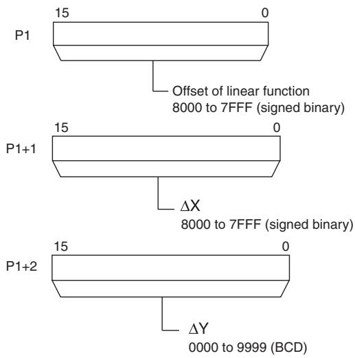
P1: First Parameter Word
Note P1 to P1 + 2 must be in the same area.
- Operand Specifications
| Area | Word addresses | Indirect DM addresses | Constants | CF | Pulse bits | TR bits | |||||||
| CIO | WR | HR | AR | T | C | DM | @DM | *DM | |||||
| S, P1, R | OK | OK | OK | OK | OK | OK | OK | OK | OK | --- | --- | --- | --- |
Flags
| Name | Label | Operation |
| Error Flag | P_ER | ON if the contents of C+1 (ΔX) is 0000. ON if the contents of C+2 (ΔY) is not BCD. OFF in all other cases. |
| Equals Flag | P_EQ | ON if the result is 0. OFF in all other cases. |
| Carry Flag | P_CY | ON if the result is negative. OFF if the result is zero or positive. |
Function
SCL2(486) is used to convert the signed binary data contained in the source word S into signed BCD data (the BCD data contains the absolute value and the Carry Flag shows the sign) and place the result in the result word R according to the linear function defined by the slope ( X, Y) and an offset. The address of the first word containing X, Y, and the offset is specified for the first parameter word P1. The sign of the result is indicated by the status of the Carry Flag (ON: negative, OFF: positive).
The following equations are used for the conversion.
$$ R = \frac {\Delta Y}{\text {B C D c o n v e r s i o n} \Delta X} \times [ (\text {B C D c o n v e r s i o n} S) - (\text {B C D c o n v e r s i o n} \text {o f t e s t}) ] $$
Note The slope of the line is Y / X
The offset and slope can be a positive value, 0, or a negative value. Using a negative slope enables reverse scaling.
- The result will be rounded to the nearest integer.
- The result in R will be the absolute BCD conversion value and the sign will be indicated by the Carry Flag. The result can thus be between -9999 and 9999.
- If the result is less than -9999 , -9999 will be output as the result. If the result is greater than 9999 , 9999 will be output.
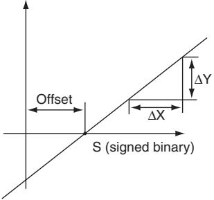
Positive Offset
R (signed BCD)
Negative Offset
R (signed BCD)
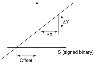
P1
P1+1
P1+2
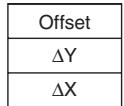
(Signed binary)
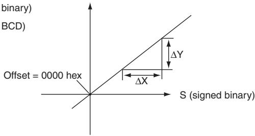
(Signed binary)
(Signed BCD)
Offset of 0000
R (signed BCD)
Hint
- SCL2(486) can be used to scale the results of analog signal conversion values from Analog Input Units according to user-defined scale parameters. For example, if a 1 to 5-V input to an Analog Input Unit is input to memory as 0000 to 0FA0 hexadecimal, the value in memory can be scaled to -100 to 200^ using SCL2(486).
- SCL2(486) converts signed binary to signed BCD. Negative values can thus be handled directly for S. The result of scaling in R and the Carry Flag can also be used to output negative values for the scaling result.
Sample program
- Scaling 1 to 5-V Analog Input to 0 to 300
In the following example, it is assumed that an analog signal from 1 to 5V is converted and input to CIO 3 as 0000 to 1770 hexadecimal. SCL2(486) is used to convert (scale) the value in CIO 3 to a value between 0000 and 0300 BCD.
When CIO 0.00 is ON, the contents of CIO 3 is scaled using the linear function defined by X (1770), Y (0300), and the offset (0). These values are contained in D100 to D102, and the result is output to D200.
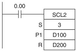
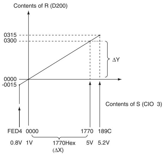
| P1: D100 | 0 | 0 | 0 | 0 | Offset |
| P1+1:D101 | 1 | 7 | 7 | 0 | ΔX |
| P1+2:D102 | 0 | 3 | 0 | 0 | ΔY |
- Scaling 1 to 5-V Analog Input to -200 to 200
In the following example, it is assume that an analog signal from 1 to 5V is converted and input to CIO 3 as 0000 to 1770 hexadecimal. SCL2(486) is used to convert (scale) the value in CIO 3 to a value between -0200 and 0200 BCD.
When CIO 0.00 is ON, the contents of CIO 3 is scaled using the linear function defined by X (1770), Y (0400), and the offset (07D0). These values are contained in D100 to D102, and the result is output to D200.
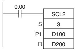
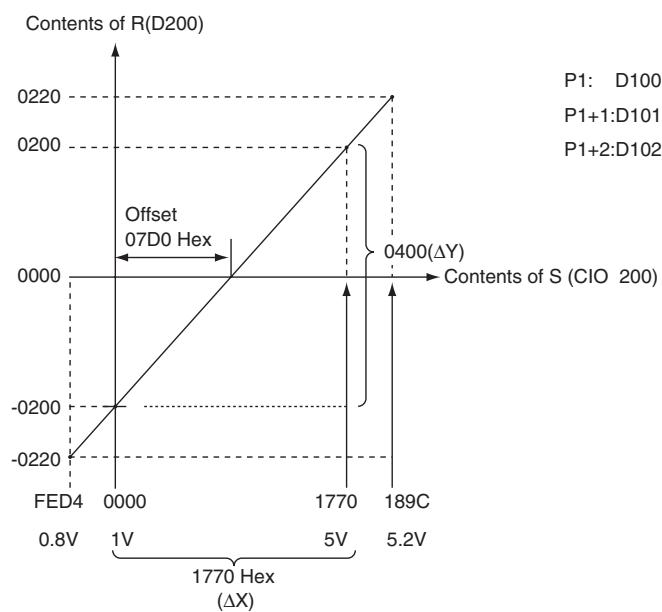
| P1: D100 | 0 | 7 | D | 0 | Offset |
| P1+1:D101 | 1 | 7 | 7 | 0 | ΔX |
| P1+2:D102 | 0 | 4 | 0 | 0 | ΔY |
SCL3
| Instruction | Mnemonic | Variations | Function code | Function |
| SCALING 3 | SCL3 | @SCL3 | 487 | Converts signed BCD data into signed binary data according to the specified linear function. An offset can be input in defining the linear function. |
| Symbol | SCL3 |
| SCL3(487) | |
| S | |
| P1 | |
| R |
Applicable Program Areas
| Area | Step program areas | Subroutines | Interrupt tasks |
| Usage | OK | OK | OK |
Operands
| Operand | Description | Data type | Size |
| S | Source word | WORD | 1 |
| P1 | First parameter word | WORD | 5 |
| R | Result word | INT | 1 |
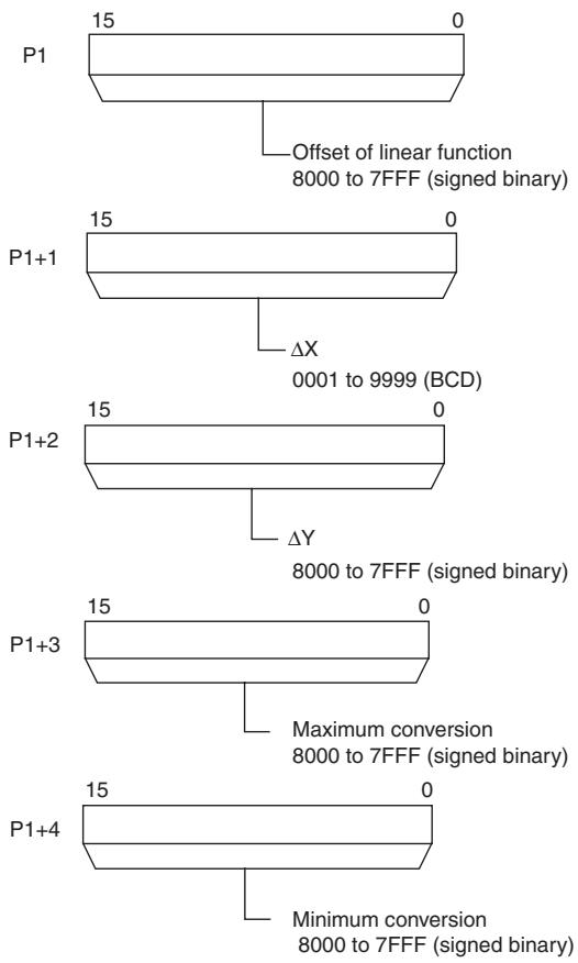
P1: First Parameter Word
Note P1 to P1 + 4 must be in the same area.
- Operand Specifications
| Area | Word addresses | Indirect DM addresses | Constants | CF | Pulse bits | TR bits | |||||||
| CIO | WR | HR | AR | T | C | DM | @DM | *DM | |||||
| S. P1,R | OK | OK | OK | OK | OK | OK | OK | OK | OK | --- | --- | --- | --- |
Flags
| Name | Label | Operation |
| Error Flag | P_ER | ON if the contents of S is not BCD.ON if the contents of C+1 (ΔX) is not between 0001 and 9999 BCDOFF in all other cases. |
| Equals Flag | P_EQ | ON if the result is 0.OFF in all other cases. |
| Negative Flag | P_N | ON when the MSB of the R (the result) is 1OFF in all other cases. |
Function
SCL3(487) is used to convert the signed BCD data (the BCD data contains the absolute value and the Carry Flag shows the sign) contained in the source word S into signed binary data and place the result in the result word R according to the linear function defined by the slope ( X, Y) and an offset. The maximum and minimum conversion values are also specified. The address of the first word containing X, Y , the offset, the maximum conversion, and the minimum conversion is specified for the first parameter word P1.
The sign of the result is indicated by the status of the Carry Flag (ON: negative, OFF: positive). Use STC(040) and CLC(041) to turn the Carry Flag ON and OFF.
The following equations are used for the conversion.
$$ R = \frac {\Delta Y}{\text {B i n a r y c o n v e r s i o n o f} \Delta X} \times ((\text {B i n a r y c o n v e r s i o n o f S}) + (\text {O f f s e t})) $$
Note The slope of the line is Y / X
- The offset and slope can be a positive value, 0, or a negative value. Using a negative slope enables reverse scaling.
- The result will be rounded to the nearest integer.
- The source value in S is treated as an absolute BCD value and the sign is indicated by the Carry Flag. The source value can thus be between -9999 and 9999.
- If the result is less than the minimum conversion value, the minimum conversion value will be output as the result. If the result is greater than the maximum conversion value, the maximum conversion value will be output.
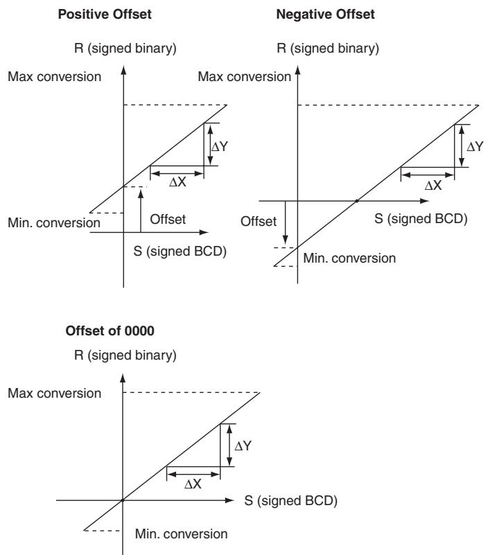
Hint
SCL3(487) is used to convert data using a user-defined scale to signed binary for Analog Output Units. For example, SCL3(487) can convert 0 to 200^ to 0000 to 1770 (hex) and output an analog output signal 1 to 5V from the Analog Output Unit.
Sample program
When a value from 0 to 200 is scaled to an analog signal (1 to 5V , for example), a signed BCD value of 0000 to 0200 is converted (scaled) to signed binary value of 0000 to 1770 for an Analog Output Unit. When CIO 0.00 turns ON in the following example, the contents of D0 is scaled using the linear function defined by X (0200), Y (1770), and the offset (0). These values are contained in D100 to D102. The sign of the BCD value in D0 is indicated by the Carry Flag. The result is output to CIO 103.

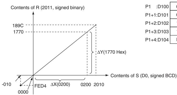
| P1 :D100 | 0 | 0 | 0 | 0 |
| P1+1:D101 | 0 | 2 | 0 | 0 |
| P1+2:D102 | 1 | 7 | 7 | 0 |
| P1+3:D103 | 1 | 8 | 9 | C |
| P1+4:D104 | F | E | D | 4 |
AVG
| Instruction | Mnemonic | Variations | Function code | Function |
| AVERAGE | AVG | --- | 195 | Calculates the average value of an input word for the specified number of cycles. |
| Symbol | AVG | |
| AVG(195) | S: Source word | |
| S | N: Number of cycles | |
| R | R: Result first word | |
Applicable Program Areas
| Area | Step program areas | Subroutines | Interrupt tasks |
| Usage | OK | OK | OK |
Operands
| Operand | Description | Data type | Size |
| S | Source word | UINT | 1 |
| N | Number of cycles | UINT | 1 |
| R | Result first word | UINT | Variable |
N: Number of Cycles
The number of cycles must be between 0001 and 0040 hexadecimal (0 to 64 cycles).
R: Result First Word and R+1: First Work Area Word
R: Average
R+1: Processing information
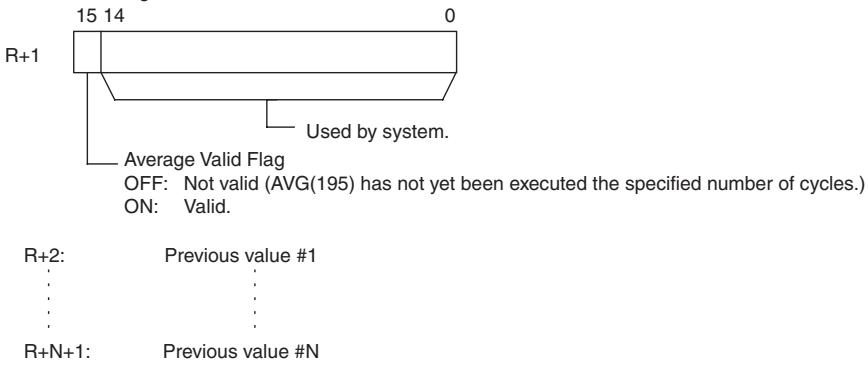
Note R to R + N + 1 must be in the same area.
-Operand Specifications
| Area | Word addresses | Indirect DM addresses | Constants | CF | Pulse bits | TR bits | |||||||
| CIO | WR | HR | AR | T | C | DM | @DM | *DM | |||||
| S, N | OK | OK | OK | OK | OK | OK | OK | OK | OK | OK | --- | --- | --- |
| R | --- | ||||||||||||
Flags
| Name | Label | Operation |
| Error Flag | P_ER | ON if the contents of N is 0. OFF in all other cases. |
Function
For the first N-1 cycles when the execution condition is ON, AVG(195) writes the values of S in order to words starting with R+2. The Previous Value Pointer (bits 00 to 07 of R+1) is incremented each time a value is written. Until the Nth value is written, the contents of S will be output unchanged to R and the Average Value Flag (bit 15 of R+1) will remain OFF.
When the Nth value is written to R + N + 1 , the average of all the values that have been stored will be computed, the average will be output to R as an unsigned binary value, and the Average Value Flag (bit 15 of R + 1 ) will be turned ON. For all further cycles, the value in R will be updated for the most current N values of S .
The maximum value of N is 64. If a value greater than 64 is specified, operation will use a value of 64.
The Previous Value Pointer will be reset to 0 after N-1 values have been written.
The average value output to R will be rounded to the nearest integer.
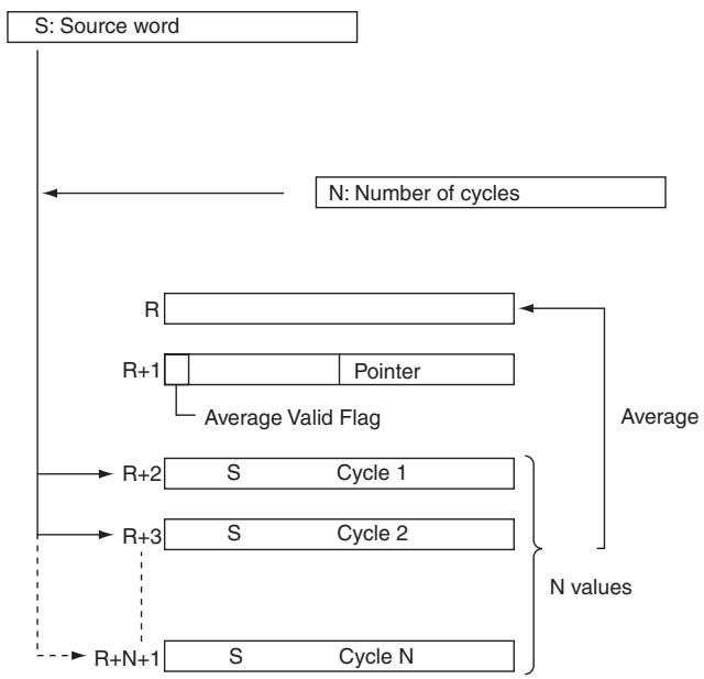
Precautions
The processing information (R + 1) is cleared to 0000 each time the execution condition changes from OFF to ON.
But the processing information (R + 1) will not be cleared to 0000 the first time the program is executed at the start of operation. If AVG(195) is to be executed in the first program scan, clear the First Work Area Word from the program.
Sample program
When CIO 0.00 is ON in the following example, the contents of D100 will be stored one time each scan for the number of scans specified in D200. The contents will be stored in order in the ten words from D302 to D311. The average of the contents of these ten words will be placed in D300 and then bit 15 of D301 will be turned ON.
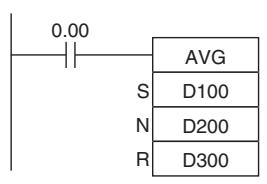
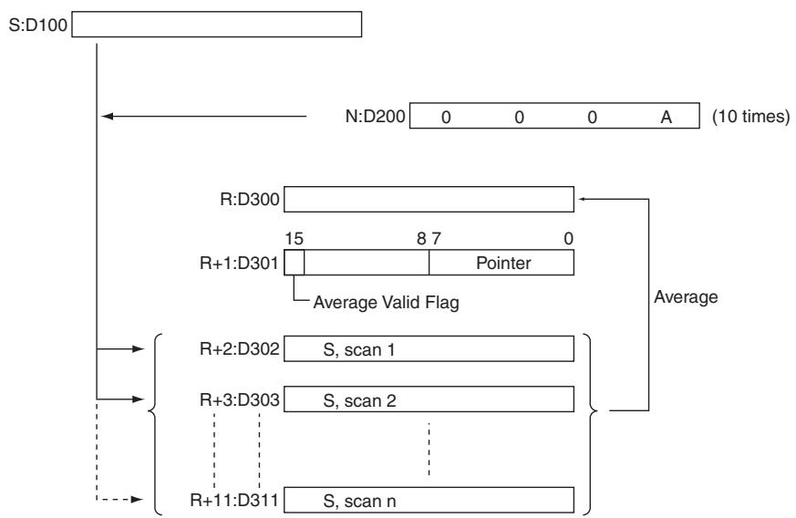
- In the following example, the content of CIO 40 is set to #0000 and then incremented by 1 each cycle.
- For the first two cycles, AVG(195) moves the content of CIO 40 to D1002 and D1003. The contents of D1001 will also change (which can be used to confirm that the results of AVG(195) has changed).
- On the third and later cycles AVG(195) calculates the average value of the contents of D1002 to D1004 and writes that average value to D1000.
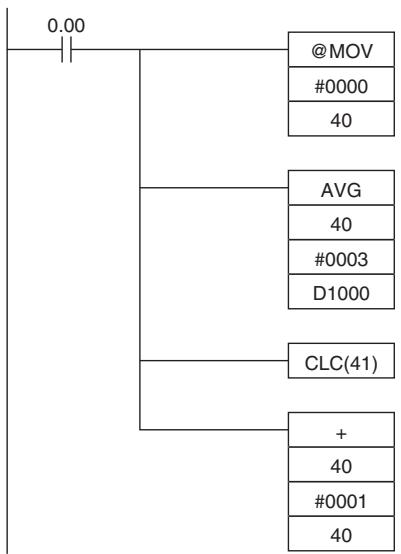
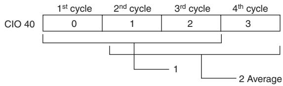
| D1000 | 0 | 1 | 1 | 2 |
| D1001 | 1 | 2 | 8000 | 8001 |
| D1002 | 0 | 0 | 0 | 3 |
| D1003 | --- | 1 | 1 | 1 |
| D1004 | --- | --- | 2 | 2 |
Average
Pointer
3 previous values of IR 40
Subroutines Instructions
SBS
| Instruction | Mnemonic | Variations | Function code | Function |
| SUBROUTINE CALL | SBS | @SBS | 091 | Calls the subroutine with the specified subroutine number and executes that program. |
| Symbol | SBS |
| SBS(091) N: Subroutine number |
Applicable Program Areas
| Area | Step program areas | Subroutines | Interrupt tasks |
| Usage | OK | OK | OK |
Operands
| Operand | Description | Data type | Size |
| N | Subroutine number | --- | 1 |
N: Subroutine number
Specifies the subroutine number between 0 and 127 decimal.
-Operand Specifications
| Area | Word addresses | Indirect DM addresses | Constants | CF | Pulse bits | TR bits | |||||||
| CIO | WR | HR | AR | T | C | DM | @DM | *DM | |||||
| N | --- | --- | --- | --- | --- | --- | --- | --- | --- | OK | --- | --- | --- |
Combined-use instructions
| Name | Label | Operation |
| Error Flag | P_ER | ON if nesting exceeds 16 levels.ON if the specified subroutine number does not exist.ON if a subroutine calls itself.ON if a subroutine being executed is called.ON if the specified subroutine is not defined in the current task.OFF in all other cases. |
Function
SBS(091) calls the subroutine with the specified subroutine number. The subroutine is the program section between SBN(092) and RET(093). When the subroutine is completed, program execution continues with the next instruction after SBS(091).
A subroutine can be called more than once in a program.
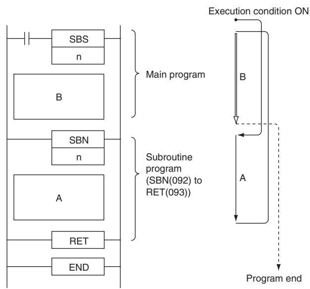
Subroutines can be nested up to 16 levels. Nesting is when another subroutine is called from within a subroutine program, such as shown in the following example, which is nested to 3 levels.
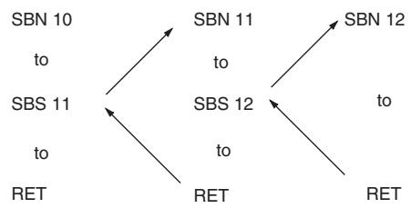
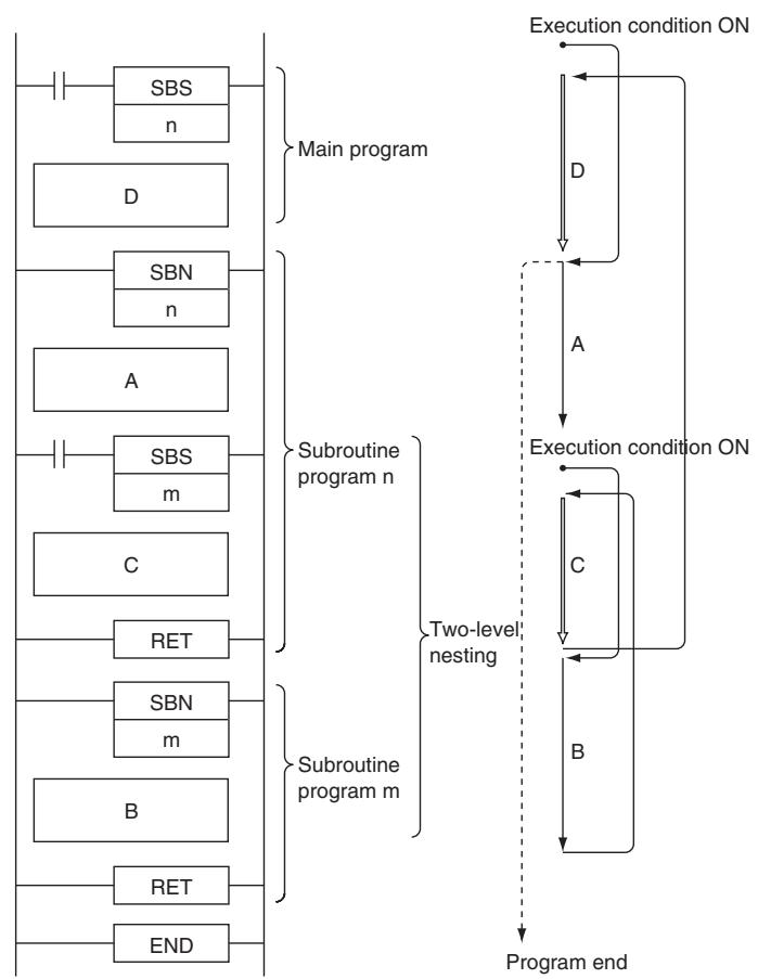
Precautions
- The subroutine number must be unique for each subroutine. You cannot use the same number for more than one subroutine.
Each subroutine must have a unique subroutine number. Do not use the same subroutine number for more than one subroutine. -
Observe the following precautions when using differentiated instructions (DIFU(013), DIFD(014), or up/down differentiated instructions) in subroutines.
-
The operation of differentiated instructions in a subroutine is unpredictable if a subroutine is executed more than once in the same cycle. In the following example, subroutine 1 is executed when CIO 0.00 is ON and CIO 1.00 is turned ON by DIFU(013) when CIO 0.01 has gone from OFF to ON. If CIO 0.01 is ON in the same cycle, subroutine 1 will be executed again but this time DIFU(013) will turn CIO 1.00 OFF without checking the status of CIO 0.01.
- In contrast, a differentiated instruction (UP, DOWN, DIFU(013) or DIFD(014)) would maintain the ON status if the instruction was executed and the output was turned ON but the same subroutine was not called a second time.
- In the following example, subroutine 1 is executed if CIO 0.00 is ON. Output CIO 1.00 is turned ON by DIFU(013) when CIO 0.01 has gone from OFF to ON. If CIO 0.00 is OFF in the following cycle, subroutine 1 will not be executed again and output CIO 1.00 will remain ON
- SBS(091) will be treated as NOP(000) when it is within a program section interlocked by IL(002) and ILC(003).
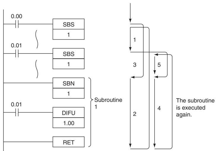
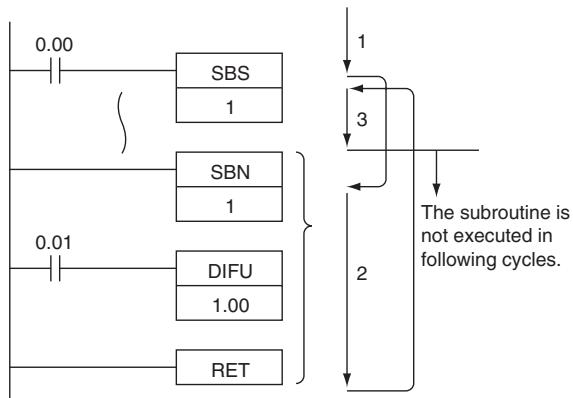
Sample program
- Sequential (Non-nested) Subroutines
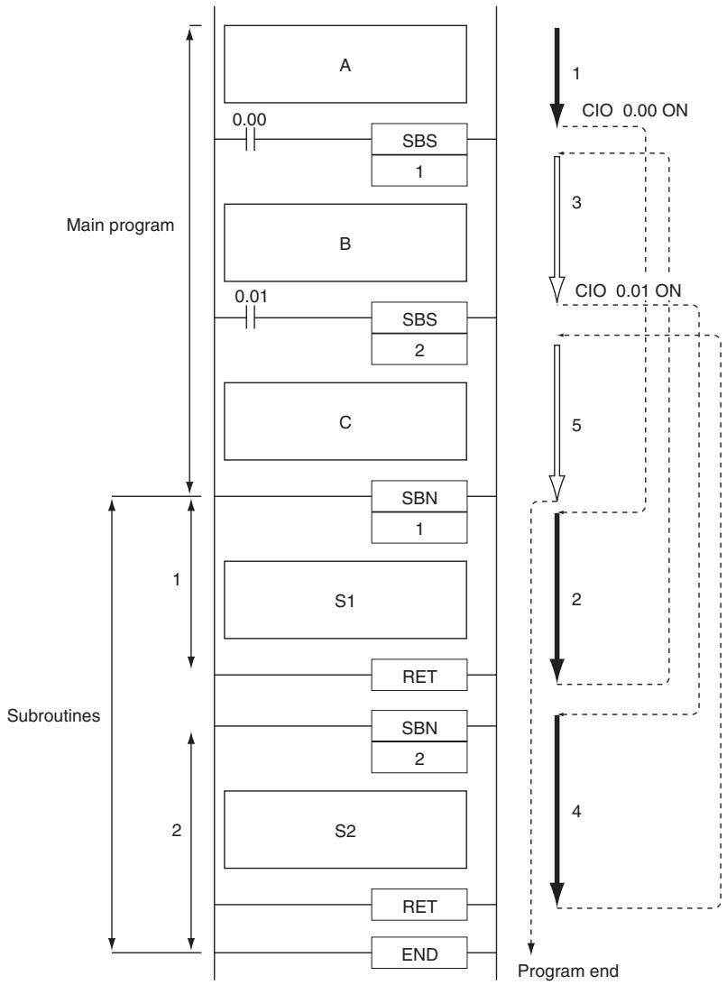
| 0.00 | 0.01 | Order of execution |
| ON | ON | A→S1→B→S2→C |
| ON | OFF | A→S1→B→C |
| OFF | ON | A→B→S2→C |
| OFF | OFF | A→B→C |
When CIO 0.00 is ON in the following example, subroutine 1 is executed and program execution returns to the next instruction after SBS(091) 1. When CIO 0.01 is ON, subroutine 2 is executed and program execution returns to the next instruction after SBS(091) 2.
- Nested Subroutines
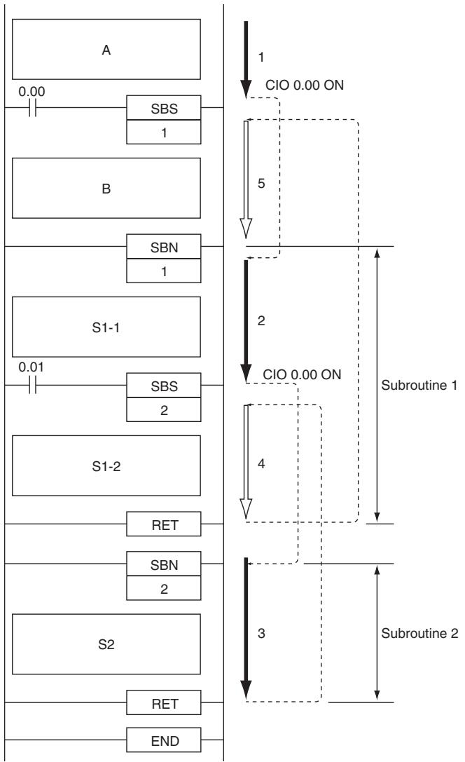
| 0.00 | 0.01 | Order of execution |
| ON | ON | A→S1-1→S2→S1-2→B |
| ON | OFF | A→S1-1→S1-2→B |
| OFF | ON | A→B |
| OFF | OFF | A→B |
When CIO 0.00 is ON in the following example, subroutine 1 is executed. If CIO 0.01 is ON, subroutine 2 is executed from within subroutine 1 and program execution returns to the next instruction after SBS(091) 2 when subroutine 2 is completed. Execution of subroutine 1 continues and program execution returns to the next instruction after SBS(091) 1 when subroutine 1 is completed.
SBN/RET
| Instruction | Mnemonic | Variations | Function code | Function |
| SUBROUTINE ENTRY | SBN | --- | 092 | Indicates the beginning of the subroutine program with the specified subroutine number. |
| SUBROUTINE RETURN | RET | --- | 093 | Indicates the end of a subroutine program. |
| Symbol | SBN | RET | ||
| SBN(092)N | N: Subroutine number | RET(093) | ||
Applicable Program Areas
SBN
| Area | Step program areas | Subroutines | Interrupt tasks |
| Usage | Not allowed | Not allowed | OK |
RET
| Area | Step program areas | Subroutines | Interrupt tasks |
| Usage | Not allowed | OK | OK |
Operands
| Operand | Description | Data type | Size |
| SBN | |||
| N | Subroutine number | --- | 1 |
- SBN
N: Subroutine number
Specifies the subroutine number between 0 and 127 decimal.
- Operand Specifications
| Area | Word addresses | Indirect DM addresses | Constants | CF | Pulse bits | TR bits | ||||||||
| CIO | WR | HR | AR | T | C | DM | @DM | *DM | ||||||
| SBN | N | --- | --- | --- | --- | --- | --- | --- | --- | --- | OK | --- | --- | --- |
Combined-use instructions
There are no flags affected by this instruction.
Function
- SBN
SBN(092) indicates the beginning of the subroutine with the specified subroutine number. The end of the subroutine is indicated by RET(093).
The region of the program beginning at the first SBN(092) instruction is the subroutine region. A subroutine is executed only when it has been called by SBS(091).
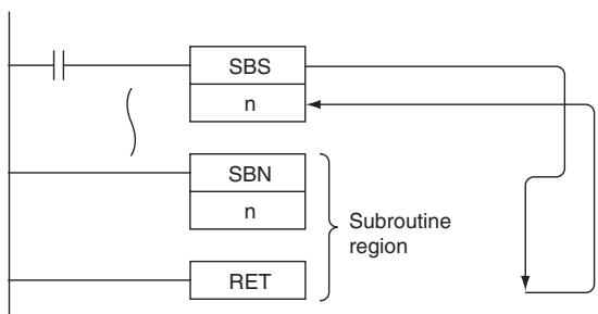
RET
When program execution reaches RET(093), it is automatically returned to the next instruction after the SBS(091) instruction that called the subroutine.
Precautions
- Place the subroutine program area (SBN(092) to RET(093)) in the same task as the SBS(091) instruction of the same number. Subroutines in other tasks cannot be called.
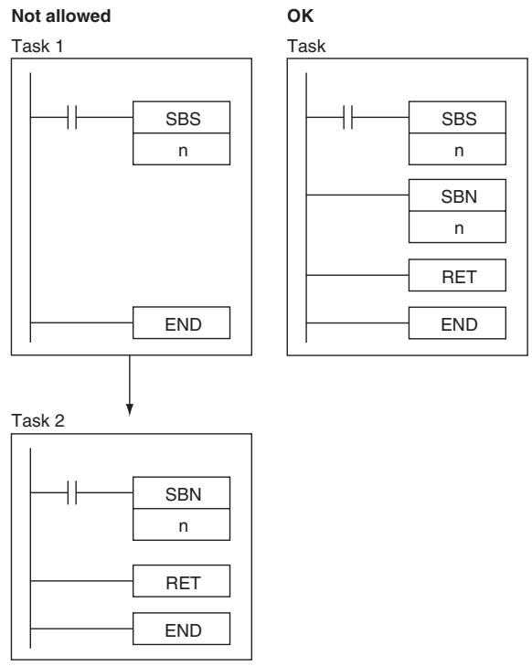
- The step instructions, STEP(008) and SNXT(009) cannot be used in subroutines.
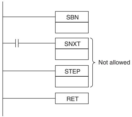
- Place the subroutines after the main program and just before the END(001) instruction in the program for each task. If part of the main program is placed after the subroutine region, that program section will be ignored.
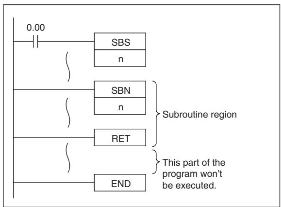
Note The input method for the subroutine number, N, is different for the CX-Programmer. Input #0 to #127 on the CX-Programmer.
Sample program
When CIO 0.00 is ON in the following example, subroutine 10 is executed and program execution returns to the next instruction after the SBS(091) or MCRO(099) instruction that called the subroutine.
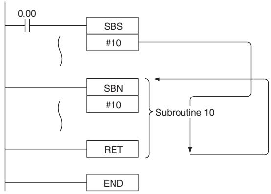
Interrupt Control Instructions
CP1E CPU Units support the following interrupts.
| Type | Execution condition | Setting procedure |
| I/O Interrupts | Interrupt input from the built-in Input on the CPU Rack turns ON/OFF. | Use the MSKS instruction to assign inputs from Interrupt Input on the CPU Rack. |
| Scheduled Interrupts | Scheduled (fixed intervals) | Use the MSKS instruction to set the interrupt interval. |
Outline of Interrupt Control Instructions
- SET INTERRUPT MASK: MSKS(690)
Both I/O interrupt tasks and scheduled interrupt tasks are masked (disabled) when the PLC enters RUN mode. MSKS(690) can be used to unmask or mask I/O interrupts and set the time intervals for scheduled interrupts.
CLEAR INTERRUPT: CLI(691)
CLI(691) clears or retains recorded interrupt inputs for I/O interrupts or sets the time to the first scheduled interrupt for scheduled interrupts. It also clears or retains recorded high-speed counter interrupts.
- DISABLE INTERRUPTS: DI(693)
DI(693) disables execution of all interrupt tasks.
- ENABLE INTERRUPTS: EI(694)
EI(694) enables execution of all interrupt tasks.
Precautions in Using Interrupt Tasks
- Precautions for All Interrupts
- When multiple interrupts occur at once, the order of execution of the interrupts is as follows: I/O interrupt > scheduled interrupt
Note "A > B" indicates that A is given priority over B. On the same interrupt level, lower numbered tasks are given priority over higher numbered tasks.
- Precautions for I/O Interrupts
- Only built-in inputs from CP1E CPU Units are supported for interrupt tasks.
- Use interrupt inputs on the CPU Rack from 0ch02 bit to 0ch07 bit. I/O interrupt tasks will not be executed if using any other input.
- All interrupt inputs that have been detected will be cleared when the interrupt mask is cleared.
- There is no limit on the number of I/O interrupt inputs that can be recorded, but only one interrupt is recorded for each I/O interrupt number. Furthermore, the recorded interrupt is not cleared until its interrupt task has been completed, so a new interrupt input will be ignored if it is received while its interrupt task is being executed.
- Precautions for Scheduled Interruptions
- Be sure that the time interval is longer than the time required to execute the scheduled interrupt task.
- To accurately control the time to the first interrupt and the interrupt interval, program CLI(691) to set the time to the first schedule interrupt just before programming MSKS(690). If MSKS(690) is used to restart a schedule interrupt, the time to the first scheduled interrupt will be accurate even if CLI(691) is not used.
- The time unit for the scheduled interrupt is always 0.1ms.
Related Memory Area Words
| Name | Address | Operation |
| Maximum Interrupt Task Processing Time | A440 | The maximum processing time for an interrupt task is stored in binary data in 0.1-ms units and is cleared at the start of operation. |
| Interrupt Task with Maximum Processing Time | A441 | The interrupt task number with maximum processing time is stored in binary data. Here, 8000 to 800F Hex correspond to task numbers 00 to 0F Hex.A441.15 will turn ON when the first interrupt occurs after the start of operation. The maximum processing time for subsequent interrupt tasks will be stored in the rightmost two digits in hexadecimal and will be cleared at the start of operation. |
MSKS
| Instruction | Mnemonic | Variations | Function code | Function |
| SET INTERRUPT MASK | MSKS | @MSKS | 690 | Controls whether I/O interrupt tasks and sched-uled interrupt tasks are executed. |
| Symbol | MSKS |
| MSKS(690) | |
| N | |
| C |
Applicable Program Areas
| Area | Step program areas | Subroutines | Interrupt tasks |
| Usage | OK | OK | OK |
Operands
| Operand | Description | Data type | Size |
| N | Interrupt identifier | --- | 1 |
| C | Control data | UINT | 1 |
(1) I/O Interrupt Task
| Operand | Contents | |
| Disabling/Enabling Interrupt Input Setting | Specifying Up/Down Differentiation of an Interrupt Input | |
| N | I/O Interrupt No. | I/O Interrupt No. |
| 102: Interrupt input 2 (interrupt task 2) | 112: Interrupt input 2 (interrupt task 2) | |
| 103: Interrupt input 3 (interrupt task 3) | 113: Interrupt input 3 (interrupt task 3) | |
| 104: Interrupt input 4 (interrupt task 4) | 114: Interrupt input 4 (interrupt task 4) | |
| 105: Interrupt input 5 (interrupt task 5) | 115: Interrupt input 5 (interrupt task 5) | |
| 106: Interrupt input 6 (interrupt task 6) | 116: Interrupt input 6 (interrupt task 6) | |
| (Cannot be used in CP1E-E10D□-□) | (Cannot be used in CP1E-E10D□-□) | |
| 107: Interrupt input 7 (interrupt task 7) | 117: Interrupt input 7 (interrupt task 7) | |
| (Cannot be used in CP1E-E10D□-□) | (Cannot be used in CP1E-E10D□-□) | |
| C | Interrupt Mask | Interrupt Mask |
| 0000 hex: Enable (unmask) the interrupt (direct mode). | 0000 hex: Up-differentiation (Detect rising edge.) | |
| 0001 hex: Disable (mask) the interrupt (direct mode). | 0001 hex: Down-differentiation (Detect falling edge.) | |
Note When the up/down differentiation setting is changed, all detected interrupt inputs will be cleared.
(2) Resetting and Starting Scheduled Interrupts
| Operand | Contents | |
| N | Scheduled Interrupt No. | |
| 4 or 14: Scheduled interrupt 0 (interrupt task 1) | ||
| C | Scheduled interrupt time units | Scheduled interrupt set time |
| Any time unit setting | 0 decimal (0000 hex): Disable interrupt. (Stop internal timer.) | |
| 0.1 ms | 10 to 9,999 decimal (000A to 270F hex): Enable interrupt. (Reset internal timer value, and then start timer with interrupt interval between 1.0 and 999.9 ms.) Note Settings 0001 to 000A cannot be used. An error will occur if one of these settings is used. | |
- Operand Specifications
| Area | Word addresses | Indirect DM addresses | Constants | CF | Pulse bits | TR bits | |||||||
| CIO | WR | HR | AR | T | C | DM | @DM | *DM | |||||
| N | --- | --- | --- | --- | --- | --- | --- | --- | --- | OK | --- | --- | --- |
| C | OK | OK | OK | OK | OK | OK | OK | OK | OK | ||||
Flags
| Name | Label | Operation |
| Error Flag | P_ER | ON if N is not within the specified range. Errors when specifying I/O Interrupts: · The Error Flag will go ON if C is not within the specified range. Errors when specifying Scheduled Interrupts: · The Error Flag will go ON if C is not between 10 and 9,999 decimal (000A to 270F hex). OFF in all other cases. |
Function
When the program execution starts, the interrupt inputs that generate I/O interrupt tasks are masked (disabled), and the internal timers creating the timer interrupts that generate scheduled interrupt tasks are stopped.
Use MSKS(690) to enable the I/O interrupts and timer interrupts, so that the corresponding interrupt tasks can be executed.
The value of N specifies the interrupt task and the kind of processing that will be performed.
(1) N = 102 to 107: Enabling/Disabling the Interrupt Inputs of I/O Interrupt Tasks
- Enables or disables the interrupt inputs specified by N, based on the status of the bits in C. With this function, MSKS(690) can control whether or not each task is executed.
- When an interrupt input is enabled, any interrupts detected up to that point will be cleared.
(2) N = 112 to 117: Specifying the Differentiation of Interrupt Inputs
- Specifies whether the interrupt inputs specified by N are up-differentiated or down-differentiated, based on the status of the bits in C.
- Use the differentiation specification together with the enabling/disabling function. If MSKS(690) is not executed to specify up or down differentiation, the interrupt inputs are up-differentiated (the default setting).
- When MSKS(690) is executed to specify an interrupt input's up or down differentiation, any interrupts detected up to that point will be cleared.
(3) N = 4 or 14: Resetting and Restarting Scheduled Interrupt Tasks
- Sets the time interval (specified by C) for the specified scheduled interrupt task (specified by N), resets the internal timer's PV, and starts the internal timer. Since the internal timer's PV is reset, this function maintains the proper interval from the execution of MSKS(690) until the start of the first interrupt.
Hint
The longest interrupt task processing time is stored in A440 (Maximum Interrupt Task Processing Time). At the same time, the task number of the interrupt task with the longest interrupt task processing time is stored in A441 (Interrupt Task with Maximum Processing Time).
Precaution
- Be sure that the time interval is longer than the time required to execute the scheduled interrupt task.
- To accurately control the time to the first interrupt and the interrupt interval, program CLI(691) to set the time to the first schedule interrupt just before programming MSKS(690). If MSKS(690) is used to restart a schedule interrupt, however, the time to the first scheduled interrupt will be accurate even if CLI(691) is not used.
- During the execution of a scheduled interrupt, the scheduled interrupt set time cannot be changed. Please change the scheduled interrupt set time after disable interrupt (stop internal timer) is set with MSKS instruction.
Sample program
Examples for Input Interrupts
When W0.00 turns ON in the following example, the first MSKS(690) (1) specifies generating input interrupts for input interrupt 3 when the interrupt input turns ON and the second MSKS(690) (2) unmarks the interrupt.
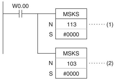
- Example for Scheduled Interrupts
When W0.01 turns ON in the following example, MSKS(690) sets the schedule interrupt interval for schedule interrupt 0 to 10.5 ms (assuming the unit is set to 0.1 ms in the PLC Setup), resets the internal timer, and starts the internal timer.
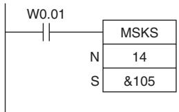
CLI
| Instruction | Mnemonic | Variations | Function code | Function |
| CLEAR INTERRUPT | CLI | @CLI | 691 | C clears/retains recorded interrupt inputs, sets the time to the first scheduled interrupt for scheduled interrupt tasks. |
| Symbol | CLI | |
| —|—|—|—|—|—|—|—|—|—|—|—|—|—|—|—|—|—|—|—|—|—|—|—|—|—|—|—|—|—|—|—|—|—|—|—|—|—|—|—|—|—|—|—|—|—|—|—|—|—|—N: Interrupt numberC: Control data | ||
| CLI(691) | ||
| N | ||
| C | ||
Applicable Program Areas
| Area | Step program areas | Subroutines | Interrupt tasks |
| Usage | OK | OK | OK |
Operands
| Operand | Description | Data type | Size |
| N | Interrupt number | --- | 1 |
| C | Control data | UINT | 1 |
(1) Clearing/Retaining an I/O Interrupt Task's Recorded Interrupt Inputs
| Operand | Contents |
| N | Interrupt Input No. |
| 102: Interrupt input 2 (interrupt task 2) | |
| 103: Interrupt input 3 (interrupt task 3) | |
| 104: Interrupt input 4 (interrupt task 4) | |
| 105: Interrupt input 5 (interrupt task 5) | |
| 106: Interrupt input 6 (interrupt task 6) (Cannot be used in CP1E-E10D□-□) | |
| 107: Interrupt input 7 (interrupt task 7) (Cannot be used in CP1E-E10D□-□) | |
| C | Recorded Interrupt |
| 0000 hex: Retain the recorded interrupt. | |
| 0001 hex: Clear the recorded interrupt. |
(2) Setting the Time to the First Scheduled Interrupts
| Operand | Contents | |
| N | Scheduled Interrupt No. | |
| 4: Interrupt task 0 (interrupt task 1) | ||
| C | Scheduled interrupt time units (Set in the PLC Setup.) | Scheduled interrupt set time |
| 0.1 ms | 10 to 9,999 decimal (000A to 270F hex): Sets time to first interrupt between 1.0 and 999.9 ms. | |
(3) Clearing/Retaining High-speed Counter Interrupts
| Operand | Contents |
| N | High-speed Counter Input |
| 10: High-speed counter input 0 | |
| 11: High-speed counter input 1 | |
| 12: High-speed counter input 2 | |
| 13: High-speed counter input 3 | |
| 14: High-speed counter input 4 | |
| 15: High-speed counter input 5 (Cannot be used in CP1E-E10D□-□) | |
| C | Recorded Interrupt |
| 0000 hex: Retain the recorded interrupt. | |
| 0001 hex: Clear the recorded interrupt. |
- Operand Specifications
| Area | Word addresses | Indirect DM addresses | Constants | CF | Pulse bits | TR bits | |||||||
| CIO | WR | HR | AR | T | C | DM | @DM | *DM | |||||
| N | --- | --- | --- | --- | --- | --- | --- | --- | --- | OK | --- | --- | --- |
| C | OK | OK | OK | OK | OK | OK | OK | OK | OK | ||||
Flags
| Name | Label | Operation |
| Error Flag | P_ER | ON if N is not within the specified range.ON if C is not 0000 or 0001 hex (for I/O interrupts or high-speed counter interrupts).ON if C is not within the specified range of 10 to 9,999 decimal (000A to 270F hex) for scheduled interrupts.OFF in all other cases. |
Function
Depending on the value of N, CLI(691) clears the specified recorded I/O interrupts, sets the time before execution of the first scheduled interrupt, or clears the specified recorded high-speed counter interrupts.
(1) N = 102 to 107: Clearing Interrupt Inputs
CLI(691) clears a recorded interrupt input specified by N, when the corresponding bit of C is ON and retains the recorded interrupt input when the corresponding bit is OFF.
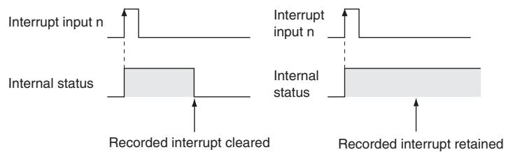
If an I/O interrupt task is being executed and an interrupt input with a different interrupt number is received, that interrupt number is recorded internally. The recorded I/O interrupts are executed later in order of their priority (from the lowest number to the highest).
If you want to ignore interrupt inputs that are received while an interrupt task is being executed, use CLI(691) to clear the recorded interrupts before they are executed.
(2) N = 4 : Setting the Time to the First Scheduled Interrupt Task
When N is 4, the content of C specifies the time interval to the first scheduled interrupt task.
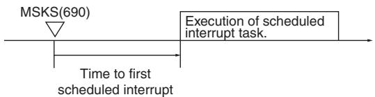
(3) N = 10 or 15: Clearing High-speed Counter Interrupts
When N is 10 or 15, CLI(691) clears or retains the recorded high-speed counter interrupt (target comparison) specified by N.
Sample program
- Example for Input Interrupts
When W0.00 turns ON in the following example, CLI(691) clears all interrupts stored for input interrupt 2.
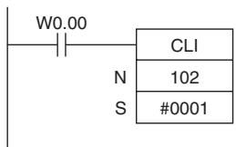
- Example for First Scheduled Interrupts
When W0.01 turns ON in the following example, CLI(691) sets the time to the first schedule interrupt 10.5 ms (0069 hex = 105 decimal).
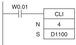
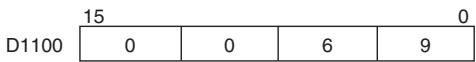
- Example for High-speed Counter Interrupts
When W0.02 turns ON in the following example, CLI(691) clears all interrupts stored for high-speed counter interrupt 0.
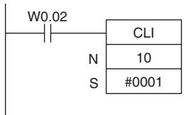
DI
| Instruction | Mnemonic | Variations | Function code | Function |
| DISABLE INTERRUPTS | DI | @DI | 693 | Disables execution of all interrupt tasks except the power OFF interrupt. |
| Symbol | DI |
| —|—|—DI(693)—|— |
Applicable Program Areas
| Area | Step program areas | Subroutines | Interrupt tasks |
| Usage | OK | OK | Not allowed |
Flags
| Name | Label | Operation |
| Error Flag | P_ER | ON if DI(693) is executed from an interrupt task. OFF in all other cases. |
Function
DI(693) is executed from the main program to temporarily disable all interrupt tasks (I/O interrupts, scheduled interrupts).
Precautions
All interrupt tasks will remain disabled until El(694) is executed.
DI(693) cannot be executed from an interrupt task.
Sample program
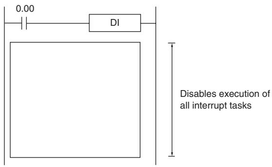
When CIO 0.00 is ON in the following example, DI(693) disables all interrupt tasks.
E
| Instruction | Mnemonic | Variations | Function code | Function |
| ENABLE INTERRUPTS | EI | --- | 694 | Enables execution of all interrupt tasks that were disabled with DI(693). |
| Symbol | EI | |
| | EI(694) | | ||
Applicable Program Areas
| Area | Step program areas | Subroutines | Interrupt tasks |
| Usage | OK | OK | Not allowed |
Flags
| Name | Label | Operation |
| Error Flag | P_ER | ON if EI(694) is executed from an interrupt taskOFF in all other cases. |
Function
- El(694) is executed from the main program to temporarily enable all interrupt tasks that were disabled by DI(693). DI(693) disables all interrupts (I/O interrupts, scheduled interrupts).
Precautions
- El(694) does not require an execution condition. It is always executed with an ON execution condition.
- EI(694) enables the interrupt tasks that were disabled by DI(693). It cannot unmask I/O interrupts that have not been unmasked by MSKS(690) or set scheduled interrupts that have not been set by MSKS(690).
- El(694) cannot be executed in an interrupt task.
Sample program
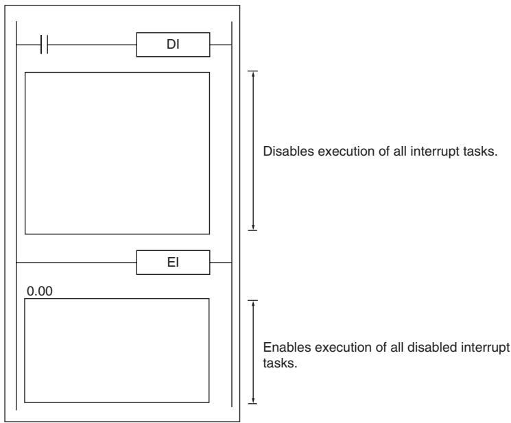
High-speed Counter/Pulse Output Instructions
INI
| Instruction | Mne-monic | Vari-ations | Function code | Function |
| MODE CONTROL | INI | @INI | 880 | INI(880) can be used to execute the following operations • To start comparison with the high-speed counter comparison table • To stop comparison with the high-speed counter comparison table • To change the PV of the high-speed counter. • To change the PV of interrupt inputs in counter mode. • To change the PV of the pulse output (origin fixed at 0). • To stop pulse output. |
| Symbol | INI | |
| — | — | |
| INI(880) | ||
| P | P: Port specifier | |
| C | C: Control data | |
| NV | NV: First word with new PV | |
Applicable Program Areas
| Area | Step program areas | Subroutines | Interrupt tasks |
| Usage | OK | OK | OK |
Operands
| Operand | Description | Data type | Size |
| P | Port specifier | WORD | 1 |
| C | Control data | UINT | 1 |
| NV | First word with new PV | DWORD | 2 |
P: Port Specifier
| P | Port |
| 0000 hex | Pulse output 0 |
| 0001 hex | Pulse output 1 |
| 0010 hex | High-speed counter 0 |
| 0011 hex | High-speed counter 1 |
| 0012 hex | High-speed counter 2 |
| 0013 hex | High-speed counter 3 |
| 0014 hex | High-speed counter 4 |
| 0015 hex | High-speed counter 5 (Cannot be used in CP1E-E10D□-□) |
| 1000 hex | PWM(891) output 0 |
C: Control Data
| C | INI(880) function |
| 0000 hex | Starts comparison. |
| 0001 hex | Stops comparison. |
| 0002 hex | Changes the PV. |
| 0003 hex | Stops pulse output. |
NV: First Word with New PV
If C is 0002 hex (i.e., when changing a PV), NV and NV + 1 contain the new PV. Any values in NV and NV + 1 are ignored when C is not 0002 hex.
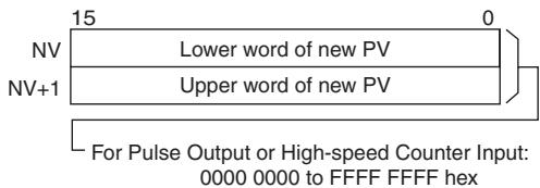
-Operand Specifications
| Area | Word addresses | Indirect DM addresses | Constants | CF | Pulse bits | TR bits | |||||||
| CIO | WR | HR | AR | T | C | DM | @DM | *DM | |||||
| P, C | --- | --- | --- | --- | --- | --- | --- | --- | --- | OK | --- | --- | --- |
| NV | OK | OK | OK | OK | OK | OK | OK | OK | OK | --- | |||
Flags
| Name | Label | Operation |
| Error Flag | P_ER | ON if the specified range for P, C, or NV is exceeded.ON if the combination of P and C is not allowed.ON if a comparison table has not been registered but starting comparison is specified.ON if a new PV is specified for a port that is currently outputting pulses.ON if changing the PV of a high-speed counter is specified for a port that is not specified for a high-speed counter.ON if INI(880) is executed in an interrupt task for a high-speed counter and an interrupt occurs when CTBL(882) is executed.OFF in all other cases. |
Function
INI(880) performs the operation specified in C for the port specified in P. The possible combinations of operations and ports are shown in the following table.
| P: Port specifier | C: Control data | |||
| 0000 hex: Start comparison | 0001 hex: Stop comparison | 0002 hex: Change PV | 0003 hex: Stop pulse output | |
| 0000 or 0001 hex: Pulse output | Not allowed. | Not allowed. | OK | OK |
| 0010 to 0015 hex: High-speed counter input | OK | OK | OK | Not allowed. |
| 1000 hex: PWM (891) output | Not allowed. | Not allowed. | Not allowed. | OK |
- Starting Comparison (C = 0000 hex)
If C is 0000 hex, INI(880) starts comparison of a high-speed counter's PV to the comparison table registered with CTBL(882).
Note A target value comparison table must be registered in advance with CTBL(882). If INI(880) is executed without registering a table, the Error Flag will turn ON.
- Stopping Comparison (C = 0001 hex)
If C is 0001 hex, INI(880) stops comparison of a high-speed counter's PV to the comparison table registered with CTBL(882).
- Changing a PV ( C = 0002 hex)
| Port and mode | Operation | Setting range | ||
| Pulse output (P = 0000 or 0001 hex) | The present value of the pulse output is changed. The new value is specified in NV and NV+1.Note This instruction can be executed only when pulse output is stopped. An error will occur if it is executed during pulse output. | 8000 0000 to 7FFF FFFF hex(-2,147,483,648 to 2,147,483,647) | ||
| High-speed counter input (P = 0010 to 0015 hex) | Linear Mode | Differential inputs, increment/decrement pulses, or pulse + direction inputs | The present value of the high-speed counter is changed. The new value is specified in NV and NV+1.Note An error will occur for the instruction if the specified port is not set for a high-speed counter. | 8000 0000 to 7FFF FFFF hex(-2,147,483,648 to 2,147,483,647) |
| Increment pulse input | 0000 0000 to FFFF FFFF hex(0 to 4,294,967,295) | |||
| Ring Mode | 0000 0000 to FFFF FFFF hex(0 to 4,294,967,295) | |||
- Stopping Pulse Output ( P = 0000 , 0001 or 1000 hex and C = 0003 hex)
If C is 0003 hex, INI(880) immediately stops pulse output for the specified port. If this instruction is executed when pulse output is already stopped, then the pulse amount setting will be cleared.
Sample program
When CIO 0.00 turns ON in the following example, SPED(885) starts outputting pulses from pulse output 0 in Continuous Mode at 500Hz . When CIO 0.01 turns ON, pulse output is stopped by INI(880).
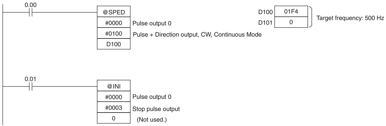
PRV
| Instruction | Mnemonic | Variations | Function code | Function |
| HIGH-SPEED COUNTER PV READ | PRV | @PRV | 881 | PRV(881) reads the High-speed counter PV and pulse output PV and interrupt input PV in counter mode. |
| Symbol | PRV | |
| — | — | PRV(881) | |
| P | ||
| C | ||
| D | ||
| P: Port specifier | ||
| C: Control data | ||
| D: First destination word | ||
Applicable Program Areas
| Area | Step program areas | Subroutines | Interrupt tasks |
| Usage | OK | OK | OK |
Operands
| Operand | Description | Data type | Size |
| P | Port specifier | --- | 1 |
| C | Control data | --- | 1 |
| D | First destination word | WORD | Variable |
P: Port Specifier
| P | Port |
| 0000 hex | Pulse output 0 |
| 0001 hex | Pulse output 1 |
| 0010 hex | High-speed counter 0 |
| 0011 hex | High-speed counter 1 |
| 0012 hex | High-speed counter 2 |
| 0013 hex | High-speed counter 3 |
| 0014 hex | High-speed counter 4 |
| 0015 hex | High-speed counter 5 (Cannot be used in CP1E-E10D□-□) |
| 1000 hex | PWM(891) output 0 |
C: Control Data
| C | PRV(881) function |
| 0000 hex | Reads the PV. |
| 0001 hex | Reads status. |
| 0002 hex | Reads range comparison results. |
| 00□3 hex | P = 0000 or 0001: Reads the output frequency of pulse output 0 or pulse output 1. C = 0003 hex P = 0010: Reads the frequency of high-speed counter input 0. C = 0013 hex: 10-ms sampling method C = 0023 hex: 100-ms sampling method C = 0033 hex: 1-s sampling method |
D: First Destination Word
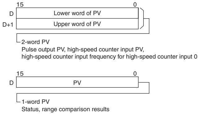
-Operand Specifications
| Area | Word addresses | Indirect DM addresses | Constants | CF | Pulse bits | TR bits | |||||||
| CIO | WR | HR | AR | T | C | DM | @DM | *DM | |||||
| P, C | --- | --- | --- | --- | --- | --- | --- | --- | --- | OK | --- | --- | --- |
| D | OK | OK | OK | OK | OK | OK | OK | OK | OK | --- | |||
Flags
| Name | Label | Operation |
| Error Flag | P_ER | ON if the specified range for P or C is exceeded.ON if the combination of P and C is not allowed.ON if reading range comparison results is specified even though range comparison is not being executed.ON if reading the output frequency is specified for anything except for high-speed counter 0.ON if specified for a port not set for a high-speed counter.OFF in all other cases. |
Function
PRV(881) reads the data specified in C for the port specified in P. The possible combinations of data and ports are shown in the following table.
| P: Port specifier | C: Control data | ||
| 0000 hex: Read PV | 0001 hex: Read status | 0002 hex: Read range comparison results | |
| 0000 or 0001 hex: Pulse output | OK | OK | Not allowed. |
| 0010 to 0015 hex: High-speed counter input | OK | OK | OK |
| 1000 hex: PWM (891) output | Not allowed. | OK | Not allowed. |
| P: Port specifier | 00□3 hex: Read frequency | |||
| 0003 hex: Pulse output read high-speed counter frequency | 0013 hex: 10-ms sampling method | 0023 hex: 100-ms sampling method | 0033 hex: 1-s sampling method | |
| 0000 or 0001 hex: Pulse output | OK | Not allowed. | Not allowed. | Not allowed. |
| 0010 or 0015 hex: High-speed counter input | Not allowed. | OK (high-speed counter 0 only) | OK (high-speed counter 0 only) | OK (high-speed counter 0 only) |
| 1000 hex: PWM (891) output | Not allowed. | Not allowed. | Not allowed. | Not allowed. |
- Reading a PV ( C = 0000 hex)
| Port and mode | Operation | Setting range | |
| Pulse output (P = 0000 or 0001 hex) | The present value of the pulse output is stored in D and D+1. | 8000 0000 to 7FFF FFFF hex(-2,147,483,648 to 2,147,483,647) | |
| High-speed counter input (P = 0010 to 0015 hex) | Linear Mode | The present value of the high-speed counter is stored in D and D+1. | 8000 0000 to 7FFF FFFF hex(-2,147,483,648 to 2,147,483,647) |
| Ring Mode | 0000 0000 to FFFF FFFF hex(0 to 4,294,967,295) | ||
- Reading Status (C = 0001 hex)
| Port and mode | Operation | Results of reading |
| Pulse output | The pulse output status is stored in D. | 0 D 15 0 0 0 0 0 0 0 0 0 0 0 0 0 0 0 0 0 0 0 0 0 0 0 0 0 0 0 0 0 0 0 0 0 0 0 0 0 0 0 0 0 0 0 0 0 0 0 0 0 0 15 0 0 0 0 0 0 0 0 0 0 0 0 0 0 0 0 0 0 0 0 0 0 0 0 0 0 0 0 0 0 0 0 0 0 0 0 0 0 0 0 0 0 0 0 0 0 0 0 15 |
| High-speed counter input | The high-speed counter status is stored in D. | 0 D 15 0 0 0 0 0 0 0 0 0 0 0 0 0 0 0 0 0 0 0 0 0 0 0 0 0 0 0 0 0 0 0 0 0 0 0 0 0 0 0 0 0 0 0 |
| PWM(891) output | The PWM(891) output is stored in D. | 0 D 15 0 0 0 0 0 0 0 0 0 0 0 0 0 0 0 0 0 0 0 0 0 0 0 0 0 0 0 0 0 0 0 0 0 0 0 0 0 0 0 0 0 0 0 15 0 0 0 0 0 |
- Reading the Results of Range Comparison (C = 0002 hex)
If C is 0002 hex, PRV(881) reads the results of range comparison and stores it in D as shown in the following diagram.
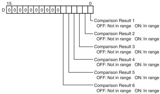
- Reading Pulse Output or High-speed Counter Frequency (C = 00□3 hex)
If C is 00□3 hex, PRV(881) reads the frequency being output from pulse output 0 or 1 or the frequency being input to high-speed counter 0 and stores it in D and D + 1 .
0000 or 0001 hex (Reading the frequency of pulse output 0 or 1)
0000 0000 to 0001 86A0 hex (0 to 100,000)
0010 hex (Reading the frequency of high-speed counter 0)
Counter input method: Any input method other than 4 × differential phase mode:
Result = 00000000 to 000186A0 hex (0 to 100,000)
Note If a frequency higher than 100kHz has been input, the output will remain at the maximum value of 000186A0 hex.
Counter input method: 4× differential phase mode:
Result = 00000000 to 00030D40 hex (0 to 200,000)
Note If a frequency higher than 200kHz has been input, the output will remain at the maximum value of 00030D40 hex.
- Pulse Frequency Calculation Methods
The function counts the number of pulses within a fixed interval (the sampling time) and calculates the frequency from that count. One of the following three sampling times can be selected by setting the rightmost two digits of C.
| Sampling time | Value of C | Description |
| 10 ms | 0013 hex | Counts the number of pulses every 10 ms. The error is 10% max. at 1 kHz. |
| 100 ms | 0023 hex | Counts the number of pulses every 100 ms. The error is 1% max. at 1 kHz. |
| 1 s | 0033 hex | Counts the number of pulses every 1 s. The error is 0.1% max. at 1 kHz. |
Precautions
If the counter is reset when P is 0010 hex (high-speed counter 0) and C is 0013, 0023, or 0033 hex (sampling method), the data read during the sampling time when the counter was reset will not be dependable.
Sample program
When CIO 0.00 turns ON in the following programming example, CTBL(882) registers a range comparison table for high-speed counter 0 and starts comparison. When CIO 0.01 turns ON, PRV(881) reads the range comparison results at that time and stores them in CIO 0100.
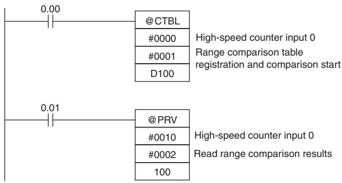
When CIO 1.00 turns ON in the following programming example, PRV(881) reads the frequency of the pulse being input to high-speed counter 0 at that time and stores it as a hexadecimal value in D200 and D201.

CTBL
| Instruction | Mnemonic | Variations | Function code | Function |
| REGISTER COMPARISON TABLE | CTBL | @CTBL | 882 | CTBL(882) is used to register a comparison table and perform comparisons for a high-speed counter PV. |
| Symbol | CTBL | |
| —|—|—CTBL(882) | —|—|—P: Port specifierC: Control dataTB: First comparison table word | |
| P | ||
| C | ||
| TB | ||
Applicable Program Areas
| Area | Step program areas | Subroutines | Interrupt tasks |
| Usage | OK | OK | OK |
Operands
| Operand | Description | Data type | Size |
| P | Port specifier | --- | 1 |
| C | Control data | --- | 1 |
| TB | First comparison table word | LWORD | Variable |
P: Port specifier
| P | Port |
| 0000 hex | High-speed counter 0 |
| 0001 hex | High-speed counter 1 |
| 0002 hex | High-speed counter 2 |
| 0003 hex | High-speed counter 3 |
| 0004 hex | High-speed counter 4 |
| 0005 hex | High-speed counter 5 (Cannot be used in CP1E-E10D□-□) |
C: Control data
| C | CTBL(882) function |
| 0000 hex | Registers a target value comparison table and starts comparison. |
| 0001 hex | Registers a range comparison table and performs one comparison. |
| 0002 hex | Registers a target value comparison table. Comparison is started with INI(880). |
| 0003 hex | Registers a range comparison table. Comparison is started with INI(880). |
TB: First comparison table word
- TB is the first word of the comparison table. The structure of the comparison table depends on the type of comparison being performed.
For target value comparison, the length of the comparison table is determined by the number of target values specified in TB. The table can be between 4 and 19 words long, as shown below.
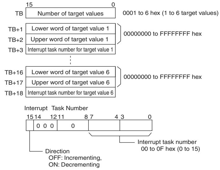
- For range comparison, the comparison table always contains six ranges. The table is 30 words long, as shown below. If it is not necessary to set six ranges, set the interrupt task number to FFFF hex for all unused ranges.
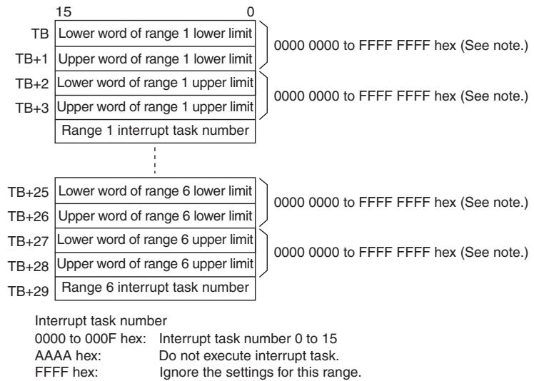
Note Always set the upper limit greater than or equal to the lower limit for any one range.
-Operand Specifications
| Area | Word addresses | Indirect DM addresses | Constants | CF | Pulse bits | TR bits | |||||||
| CIO | WR | HR | AR | T | C | DM | @DM | *DM | |||||
| P, C | --- | --- | --- | --- | --- | --- | --- | --- | --- | OK | --- | --- | --- |
| TB | OK | OK | OK | OK | OK | OK | OK | OK | OK | --- | |||
Flags
| Name | Label | Operation |
| Error Flag | P_ER | ON if the specified range for P or C is exceeded.ON if the number of target values specified for target value comparison is set to 0.ON if the number of target values specified for target value comparison exceeds 6.ON if the upper value is less than the lower value for any range.ON if the set values for all ranges are disabled during a range comparison.ON if the high-speed counter is set for incremental pulse mode and decrementing is set in the table as the direction for comparison.ON if the same target value is specified more than once in the same comparison direction for target comparison when the high-speed counter is set to incremental pulse mode and linear mode.ON if an instruction is executed when the high-speed counter is set to Ring Mode and the specified value exceeds the maximum ring value.ON if specified for a port not set for a high-speed counter.ON if executed for a different comparison method while comparison is already in progress.OFF in all other cases. |
Function
CTBL(882) registers a comparison table and starts comparison for the port specified in P and the method specified in C. Once a comparison table is registered, it is valid until a different table is registered or until the CPU Unit is switched to PROGRAM mode.
Each time CTBL(882) is executed, comparison is started under the specified conditions. When using CTBL(882) to start comparison, it is normally sufficient to use the differentiated version (@CTBL(882)) of the instruction or an execution condition that is turned ON only for one scan.
Note If an interrupt task that has not been registered is specified, a fatal program error will occur the first time an interrupt is generated.
- Registering a Comparison Table (C = 0002 or 0003 hex)
If C is set to 0002 or 0003 hex, a comparison table will be registered, but comparison will not be started. Comparison is started with INI(880).
- Registering a Comparison Table and Starting Comparison (C = 0000 or 0001 hex)
If C is set to 0000 or 0001 hex, a comparison table will be registered, and comparison will be started.
- Stopping Comparison
Comparison is stopped with INI(880). It makes no difference what instruction was used to start comparison.
- Target Value Comparison
The corresponding interrupt task is called and executed when the PV matches a target value.
- The same interrupt task number can be specified for more than one target value.
- The direction can be set to specify whether the target value is valid when the PV is being incremented or decremented. If bit 15 in the word used to specify the interrupt task number for the range is OFF, the PV will be compared to the target value only when the PV is being incremented, and if bit 00 is ON, only when the PV is being decremented.
- The comparison table can contain up to 6 target values, and the number of target values is specified in TB (i.e., the length of the table depends on the number of target values that is specified).
- Comparisons are performed for all target values registered in the table.
Note 1 An error will occur if the same target value with the same comparison direction is registered more than once in the same table.
2 If the high-speed counter is set for incremental pulse mode, an error will occur if decrementing is set in the table as the direction for comparison.
3 If the count direction changes while the PV equals a target value that was reached in the direction opposite to that set as the comparison direction, the comparison condition for that target value will not be met. Do not set target values at peak and bottom values of the count value.
- Range Comparison
The corresponding interrupt task is called and executed when the PV enters a set range.
- The same interrupt task number can be specified for more than one target value.
- The range comparison table contains 6 ranges, each of which is defined by a lower limit and an upper limit. If a range is not to be used, set the interrupt task number to FFFF hex to disable the range.
- The interrupt task is executed only once when the PV enters the range. If the PV is within more than one range when the comparison is made, the interrupt task for the range closest to the beginning of the table will be given priority and other interrupt tasks will be executed in following cycles.
- If there is no reason to execute an interrupt task, specify AAAA hex as the interrupt task number. The range comparison results can be read with PRV(881) or using the Range Comparison In-progress Flags.
Note An error will occur if the upper limit is less than the lower limit for any one range.
Sample program
When CIO 0.00 turns ON in the following programming example, CTBL(882) registers a target value comparison table and starts comparison for high-speed counter 0. The PV of the high-speed counter is counted incrementally and when it reaches 500, it equals target value 1 and interrupt task 1 is executed. When the PV is incremented to 1000, it equals target value 2 and interrupt task 2 is executed.
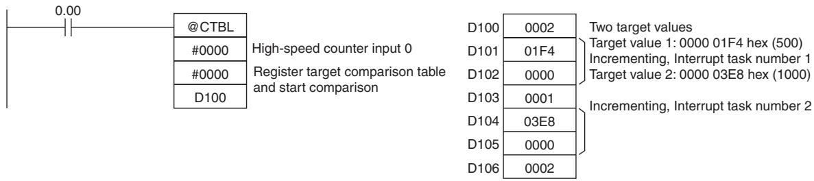
SPED
| Instruction | Mnemonic | Variations | Function code | Function |
| SPEED OUTPUT | SPED | @SPED | 885 | SPED(885) is used to set the output pulse frequency for a specific port and start pulse output without acceleration or deceleration. |
| Symbol | SPED | |
| — | — | SPED(855) — | |
| P | P: Port specifier | |
| M | M: Output mode | |
| F | F: First pulse frequency word | |
Applicable Program Areas
| Area | Step program areas | Subroutines | Interrupt tasks |
| Usage | OK | OK | OK |
Operands
| Operand | Description | Data type | Size |
| P | Port specifier | UINT | 1 |
| M | Output mode | WORD | 1 |
| F | First pulse frequency word | UDINT | 2 |
P: Port specifier
| P | Port |
| 0000 hex | Pulse output 0 |
| 0001 hex | Pulse output 1 |
M: Output mode
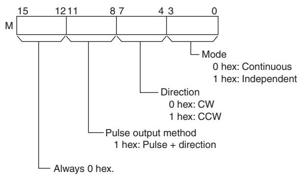
F: First pulse frequency word
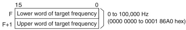
Specify the pulse frequency in Hz.
- Operand Specifications
| Area | Word addresses | Indirect DM addresses | Constants | CF | Pulse bits | TR bits | |||||||
| CIO | WR | HR | AR | T | C | DM | @DM | *DM | |||||
| P, M | --- | --- | --- | --- | --- | --- | --- | --- | --- | OK | --- | --- | --- |
| F | OK | OK | OK | OK | OK | OK | OK | OK | OK | --- | |||
Flags
| Name | Label | Operation |
| Error Flag | P_ER | ON if the specified range for P, M, or F is exceeded.ON if PLS2(887) or ORG(889) is already being executed to control pulse output for the specified port.ON if SPED(885) or INI(880) is used to change the mode between continuous and independent output during pulse output.ON if SPED(885) is executed in an interrupt task when an instruction controlling pulse output is being executed in a cyclic task.ON if SPEC(885) is executed in independent mode with an absolute number of pulses and the origin has not been established.OFF in all other cases. |
Function
SPED(885) starts pulse output on the port specified in P using the method specified in M at the frequency specified in F. Pulse output will be started each time SPED(885) is executed. It is thus normally sufficient to use the differentiated version (@SPED(885)) of the instruction or an execution condition that is turned ON only for one scan.
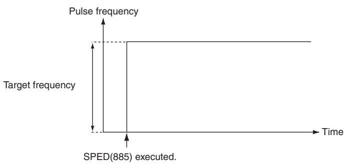
In independent mode, pulse output will stop automatically when the number of pulses set with PULS(886) in advance have been output. In continuous mode, pulse output will continue until stopped from the program.
An error will occur if the mode is changed between independent and continuous mode while pulses are being output.
Note SPED instruction can be used only with transistor output type of CP1E N/NA-type CPU Unit.
In case of transistor output type of CP1E E-type CPU Unit or relay output type, NOP processing is applied.
Continuous Mode Speed Control
When continuous mode operation is started, pulse output will be continued until it is stopped from the program.
Note Pulse output will stop immediately if the CPU Unit is changed to PROGRAM mode.
| Operation | Purpose | Application | Frequency changes | Description | Procedure/ instruction |
| Starting pulse output | To output with speci-fied speed | Changing the speed (fre-quence) in one step | Pulse frequency Target frequency Time Execution of SPED(885) | Outputs pulses at a specified frequency. | SPED(885) (Continu-ous) |
| Changing settings | To change speed in one step | Changing the speed during operation | Pulse frequency Target frequency Present frequency Execution of SPED(885) | Changes the fre-quence (higher or lower) of the pulse out-put in one step. | SPED(885) (Continu-ous) ↓ SPED(885) (Continu-ous) |
| Stopping pulse output | Stop pulse output | Immediate stop | Pulse frequency Present frequency Time Execution of INI(880) | Stops the pulse output immediately. | SPED(885) (Continu- ous) ↓ INI(880) |
| Stop pulse output | Immediate stop | Pulse frequency Present frequency Time Execution of SPED(885) | Stops the pulse output immediately. | SPED(885) (Continu- ous) ↓ SPED(885) (Continu- ous, Target frequency of 0 Hz) |
- Independent Mode Positioning
When independent mode operation is started, pulse output will be continued until the specified number of pulses has been output.
Note - Pulse output will stop immediately if the CPU Unit is changed to PROGRAM mode.
- The number of output pulses must be set each time output is restarted.
- The number of output pulses must be set in advance with PULS(881). Pulses will not be output for SPED(885) if PULS(881) is not executed first.
- The direction set in the SPED(885) operand will be ignored if the number of pulses is set with PULS(881) as an absolute value.
| Operation | Purpose | Application | Frequency changes | Description | Procedure/ instruction |
| Starting pulse output | To output with specified speed | Positioning without acceleration or deceleration | Pulse frequency Specified number of pulses (Specified with PULS(886).) | Starts outputting pulses at the specified frequency and stops immediately when the specified number of pulses has been output. | PULS(886) ↓ |
| Target frequency Execution of SPED(885) Outputs the specified number of pulses and then stops. | Note The target position (number of pulses) cannot be changed during positioning (pulse output). | SPED(885) (Independent) | |||
| Changing settings | To change speed in one step | Changing the speed in one step during operation | Pulse frequency Specified number of pulses (Specified with PULS(886).) Number of pulses specified with PULS(886) does not change. Execution of SPED(885) (independent mode) SPED(885) (independent mode) executed again to change the target frequency. (The target position is not changed.) | SPED(885) can be executed during position- ing to change (raise or lower) the pulse output frequency in one step. The target position (specified number of pulses) is not changed. | PULS(886) ↓ |
| SPED(885) (Independent) ↓ | |||||
| SPED(885) (Independent) | |||||
| Stopping pulse output | To stop pulse output (Number of pulses setting is not preserved.) | Immediate stop | Pulse frequency Present frequency Time Execution of SPED(885) Execution of INI(880) | Stops the pulse output immediately and clears the number of output pulses setting. | PULS(886) ↓ SPED(885) (Independent) ↓ INI(880) |
| Stop pulse output (Number of pulses setting is not preserved.) | Immediate stop | Pulse frequency Present frequency Time Execution of SPED(885) Execution of SPED(885) | Stops the pulse output immediately and clears the number of output pulses setting. | PULS(886) ↓ SPED(885) (Independent) ↓ SPED(885), (Independent, Target frequency of 0 Hz) |
Sample program
When CIO 0.00 turns ON in the following programming example, PULS(886) sets the number of output pulses for pulse output 0. An absolute value of 5,000 pulses is set. SPED(885) is executed next to start pulse output using the pulse + direction method in the clockwise direction in independent mode at a target frequency of 500Hz .
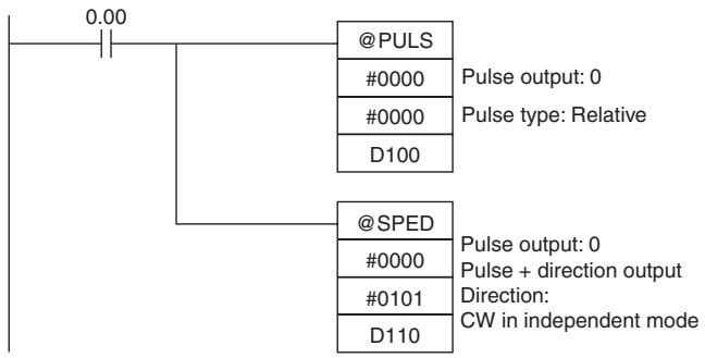
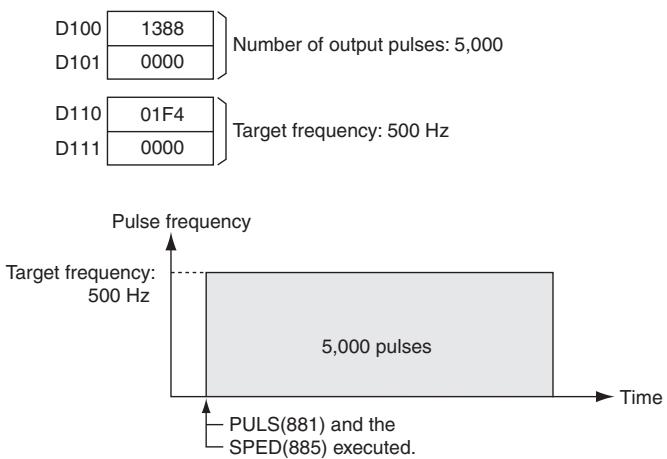
PULS
| Instruction | Mnemonic | Variations | Function code | Function |
| SET PULSES | PULS | @PULS | 886 | PULS(886) is used to set the pulse output amount (number of out-put pulses). |
| Symbol | PULS | |
| — | — PULS(886) — | ||
| P | P: Port specifier | |
| T | T: Pulse type | |
| N | N: Number of pulses | |
Applicable Program Areas
| Area | Step program areas | Subroutines | Interrupt tasks |
| Usage | OK | OK | OK |
Operands
| Operand | Description | Data type | Size |
| P | Port specifier | --- | 1 |
| T | Pulse type | --- | 1 |
| N | Number of pulses | DINT | 2 |
P: Port specifier
| P | Port |
| 0000 hex | Pulse output 0 |
| 0001 hex | Pulse output 1 |
T: Pulse type
| T | Pulse type |
| 0000 hex | Relative |
| 0001 hex | Absolute |
N and N+1: Number of pulses
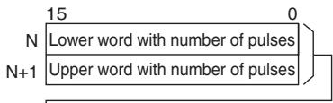
Relative pulse output:
0 to 2,147,483,647 (0000 0000 to 7FFF FFFF hex)
Absolute pulse output:
-2,147,483,648 to 2,147,483,647 (80000000 to 7FFF FFFF hex)
- The actual number of movement pulses that will be output are as follows:
For relative pulse output, the number of movement pulses = the set number of pulses.
For absolute pulse output, the number of movement pulses = the set number of pulses - the PV.
- Operand Specifications
| Area | Word addresses | Indirect DM addresses | Constants | CF | Pulse bits | TR bits | |||||||
| CIO | WR | HR | AR | T | C | DM | @DM | *DM | |||||
| P,T | --- | --- | --- | --- | --- | --- | --- | --- | --- | OK | --- | --- | --- |
| N | OK | OK | OK | OK | OK | OK | OK | OK | OK | ||||
Flags
| Name | Label | Operation |
| Error Flag | P_ER | ON if the specified range for P, T, or N is exceeded.ON if PULS(886) is executed for a port that is already outputting pulses.ON if PULS(886) is executed in an interrupt task when an instruction controlling pulse output is being executed in a cyclic task.OFF in all other cases. |
Function
PULS(886) sets the pulse type and number of pulses specified in T and N for the port specified in P. Actual output of the pulses is started later in the program using SPED(885) or ACC(888) in independent mode.
Note
- An error will occur if PULS(886) is executed when pulses are already being output. Use the differentiated version (@PULS(886)) of the instruction or an execution condition that is turned ON only for one scan to prevent this.
- The calculated number of pulses output for PULS(886) will not change even if INI(880) is used to change the PV of the pulse output.
- The direction set for SPED(885) or ACC(888) will be ignored if the number of pulses is set with PULS(881) as an absolute value.
- It is possible to move outside of the range of the PV of the pulse output amount (-2,147,483,648 to 2,147,483,647).
- PULS instruction can be used only with transistor output type of CP1E N/NA-type CPU Unit. In case of transistor output type of CP1E E-type CPU Unit or relay output type, NOP processing is applied.
Sample program
When CIO 0.00 turns ON in the following programming example, PULS(886) sets the number of output pulses for pulse output 0. An absolute value of 5,000 pulses is set. SPED(885) is executed next to start pulse output using the pulse + direction method in the clockwise direction in independent mode at a target frequency of 500Hz .
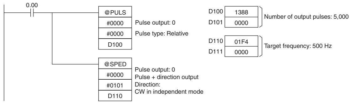
PLS2
| Instruction | Mnemonic | Variations | Function code | Function |
| PULSE OUTPUT | PLS2 | @PLS2 | 887 | PLS2(887) outputs a specified number of pulses to the specified port. Pulse output starts at a spec-ified startup frequency, accelerates to the target frequency at a specified acceleration rate, decel-erates at the specified deceleration rate, and stops at approximately the same frequency as the start-up frequency. |
| Symbol | PLS2 | |
| —|—|—|—|—|—|—|—|—|—|—|—|—|—|—|—|—|—|—|—|—|—|—|—|—|—|—|—|—|—|—|—|—|—|—|—|—|—|—|—|—|—|—|—|—|—|—|—|—|—|— | —|—|—|—|—|—|—|—|—|—|—|—|—|—|—|—|—|—|—|—|—|—|—|—|—|—|—|—|—|—|—|—|—|—|—|—|—|—|—|—|—|—|—|—|—|—|—|—|—|−P: Port specifierM: Output modeS: First word of settings tableF: First word of starting frequency | |
| PLS2(887) | ||
| P | ||
| M | ||
| S | ||
| F | ||
Applicable Program Areas
| Area | Step program areas | Subroutines | Interrupt tasks |
| Usage | OK | OK | OK |
Operands
| Operand | Description | Data type | Size |
| P | Port specifier | --- | 1 |
| M | Output mode | --- | 1 |
| S | First word of settings table | WORD | 6 |
| F | First word of starting frequency | UDINT | 2 |
P: Port Specifier
| P | Port |
| 0000 hex | Pulse output 0 |
| 0001 hex | Pulse output 1 |
M: Output Mode
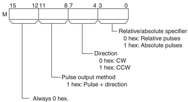
S: First Word of Settings Table
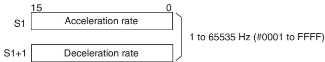
Specify the increase or decrease in the frequency per pulse control period (4 ms).
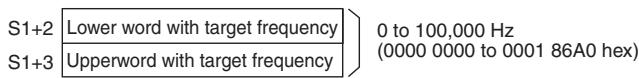
Specify the frequency after acceleration/deceleration in Hz.
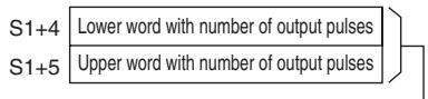
Relative pulse output: 0 to 2.147,483,647
(0000 0000 to 7FFF FFFF hex)
Absolute pulse output: -2,147,483,648 to 2,147,483,647
(8000 0000 to 7FFF FFFF hex)
The actual number of movement pulses that will be output are as follows:
- For relative pulse output, the number of movement pulses = the set number of pulses.
- For absolute pulse output, the number of movement pulses = the set number of pulses – the PV.
F: First Word of Starting Frequency
The starting frequency is given in F and F + 1
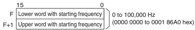
Specify the starting frequency in Hz.
- Operand Specifications
| Area | Word addresses | Indirect DM addresses | Constants | CF | Pulse bits | TR bits | |||||||
| CIO | WR | HR | AR | T | C | DM | @DM | *DM | |||||
| P, M | --- | --- | --- | --- | --- | --- | --- | --- | --- | OK | --- | --- | --- |
| S | OK | OK | OK | OK | OK | OK | OK | OK | OK | --- | |||
| F | OK | ||||||||||||
Flags
| Name | Label | Operation |
| Error Flag | P_ER | ON if the specified range for P, M, S, or F is exceeded.ON if PLS2(887) is executed for a port that is already outputting pulses for SPED(885) or ORG(889).ON if PLS2(887) is executed in an interrupt task when an instruction controlling pulse output is being executed in acyclic task.ON if PLS2(887) is executed for an absolute pulse output but the origin has not been established.OFF in all other cases. |
Function
PLS2(887) starts pulse output on the port specified in P using the mode specified in M at the start frequency specified in F (1 in diagram).
The frequency is increased every pulse control period (4 ms) at the acceleration rate specified in S until the target frequency specified in S is reached (2 in diagram).
When the target frequency has been reached, acceleration is stopped and pulse output continues at a constant speed (3 in diagram).
The deceleration point is calculated from the number of output pulses and deceleration rate set in S and when that point is reached, the frequency is decreased every pulse control period (4 ms) at the deceleration rate specified in S until the starting frequency specified in S is reached, at which point pulse output is stopped (4 in diagram).
Pulse output is started each time PLS2(887) is executed. It is thus normally sufficient to use the differentiated version (@PLS2(887)) of the instruction or an execution condition that is turned ON only for one scan.
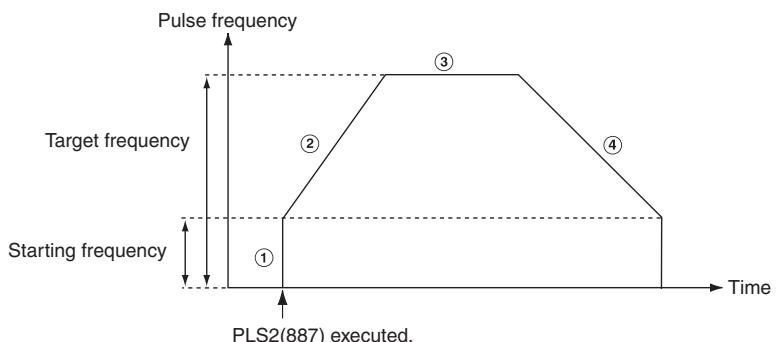
PLS2(887) can be used only for positioning.
With the CJ1M CPU Units, PLS2(887) can be executed during pulse output for ACC(888) in either independent or continuous mode, and during acceleration, constant speed, or deceleration. (See notes 1 and 2.) ACC(888) can also be executed during pulse output for PLS2(887) during acceleration, constant speed, or deceleration.
Note 1 Executing PLS2(887) during speed control with ACC(888) (continuous mode) with the same target frequency as ACC(888) can be used to achieve interrupt feeding of a fixed distance. Acceleration will not be performed by PLS2(887) for this application, but if the acceleration rate is set to 0, the Error Flag will turn ON and PLS2(887) will not be executed. Always set the acceleration rate to a value other than 0.
2 If PLS2 (887) is executed during the period from pulse output stop to one cycle after the stop (when pulse output in-progress flag is ON), pulse output will start again in the next cycle after stopping. However, if pulse output is stopped by INI (880), the pulse output instruction will become invalid within one cycle after the stop. Execute the instruction till the pulse output in-progress flag is OFF.
3 PLS2 instruction can be used only with transistor output type of CP1E N/NA-type CPU Unit. In case of transistor output type of CP1E E-type CPU Unit or relay output type, NOP processing is applied.
- Independent Mode Positioning
Note Pulse output will stop immediately if the CPU Unit is changed to PROGRAM mode.
| Operation | Purpose | Application | Frequency changes | Description | Procedure/instruction |
| Starting pulse output | Complex trapezoidal control | Positioning with trapezoidal acceleration and deceleration (Separate rates used for acceleration and deceleration; starting speed) The number of pulses can be changed during positioning. | Pulse frequency Specified number of pulses Target frequency Acceleration rate Deceleration rate Stop frequency Time Execution of PLS2(887) Target frequency Deceleration point reached. | Accelerates and decelerates at a fixed rates. The pulse output is stopped when the specified number of pulses has been output. (See note.) Note The target position (specified number of pulses) can be changed during positioning. | PLS2(887) |
| Changing settings | To change speed smoothly (with unequal acceleration and deceleration rates) | Changing the target speed (frequency) during positioning (different acceleration and deceleration rates) | Pulse frequency Specified number of pulses (Specified with PULS(886).) Change target frequency Acceleration/ deceleration rate Time Execution of ACC(888) (independent mode) PLS2(887) executed to change the target frequency and acceleration/deceleration rates. (The original target position is specified again.) | PLS2(887) can be executed during positioning to change the acceleration rate, deceleration rate, and target frequency. Note To prevent the target position from being changed intentionally, the original target position must be specified in absolute coordinates. | PLS2(887) ↓ PLS2(887) |
| PULS(886) ↓ ACC(888) (Independent) ↓ PLS2(887) | |||||
| To change target position | Changing the target position during positioning (multi-ple start function) | Pulse frequency Specified number of pulses Target frequency Acceleration/ deceleration rate Time Execution of PLS2(887) PLS2(887) executed to change the target position. (The target frequency and acceleration/deceleration rates are not changed.) | PLS2(887) can be executed during positioning to change the target position (number of pulses), acceleration rate, deceleration rate, and target frequency. Note If a constant speed cannot be maintained after changing the settings, an error will occur and the original operation will continue to the original target position. | PLS2(887) ↓ PLS2(887) | |
| PULS(886) ↓ ACC(888) (Independent) ↓ PLS2(887) | |||||
| To change target position and speed smoothly | Changing the target position and target speed (frequency) during positioning (multi-ple start function) | Pulse frequency Specified number of pulses (Specified with PLS2(887)). Change target frequency Acceleration/ deceleration rate Time Execution of PLS2(887) PLS2(887) executed to change the target frequency, acceleration rate and deceleration rate. | PLS2(887) can be executed during positioning to change the target position (number of pulses), acceleration rate, deceleration rate, and target frequency. Note If a constant speed cannot be maintained after changing the settings, an error will occur and the original operation will continue to the original target position. | PULS(886) ↓ ACC(888) (Independent) ↓ PLS2(887) | |
| PLS2(887) ↓ PLS2(887) | |||||
| Changing settings, continued | To change target position and speed smoothly, continued | Changing the acceleration and deceleration rates during positioning (multiple start function) | Pulse frequency New target frequency Original target frequency Execution of PLS2(887) #1 Execution of PLS2(887) #3 Execution of PLS2(887) #2 | PLS2(887) can be executed during positioning (acceleration or deceleration) to change the acceleration rate or deceleration rate. | PULS(886) ↓ ACC(888) (Independent) ↓ PLS2(887) |
| To change direction | Changing the direction during positioning | Pulse frequency Target frequency Execution of PLS2(887) #1 Execution of PLS2(887) #2 | PLS2(887) can be executed during positioning with absolute pulse specification to change to absolute pulses and reverse direction. | PLS2(887) ↓ PLS2(887) | |
| Stopping pulse output | Stop pulse output (Number of pulses setting is not preserved.) | Immediate stop | Pulse frequency Present frequency Execution of SPED(885) | Stops the pulse output immediately and clears the number of output pulses. | PLS2(887) ↓ INI(880) |
| Stop pulse output smoothly. (Number of pulses setting is not preserved.) | Decelerate to a stop | Pulse frequency Present frequency Target frequency = 0 Execution of PLS2(887) | Decelerates the pulse output to a stop. | PLS2(887) ↓ ACC(888) (Independent, target frequency of 0 Hz) |
Note Triangular Control
If the specified number of pulses is less than the number required to reach the target frequency and return to zero, the function will automatically reduce the acceleration/deceleration time and perform triangular control (acceleration and deceleration only.) An error will not occur.
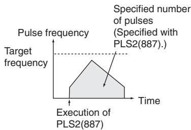
- Switching from Continuous Mode Speed Control to Independent Mode Positioning
| Example application | Frequency changes | Description | Procedure/ instruction |
| Change from speed control to fixed distance positioning during operation | Pulse frequency Target frequency Execution of ACC(888) (continuous mode) Time Execution of PLS2(887) | PLS2(887) can be executed during a speed control operation started with ACC(888) to change to positioning operation. | ACC(888) (Continuous) ↓ PLS2(887) |
| Fixed distance feed interrupt | Pulse frequency Present frequency Execution of ACC(888) (continuous mode) Time Execution of PLS2(887) with the following settings ·Number of pulses = number of pulses until stop ·Relative pulse specification ·Target frequency = present frequency ·Acceleration rate = 0001 to 07D0 hex ·Deceleration rate = target deceleration rate |
Sample program
When CIO 0.00 turns ON in the following programming example, PLS2(887) starts pulse output from pulse output 0 with an absolute pulse specification of 100,000 pulses. Pulse output is accelerated at a rate of 500Hz every 4 ms starting at 200Hz until the target speed of 50kHz is reached. From the deceleration point, the pulse output is decelerated at a rate of 250Hz every 4 ms starting until the starting speed of at 200Hz is reached, at which point pulse output is stopped.
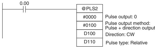
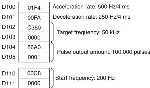
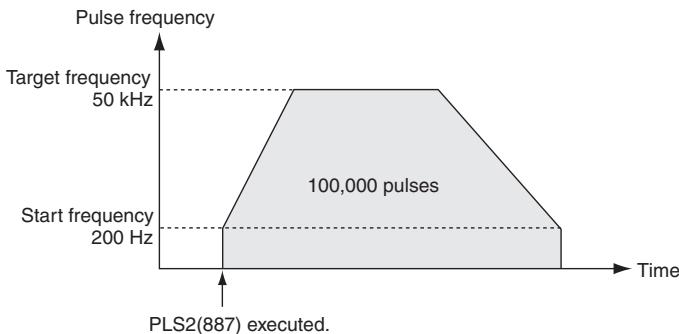
ACC
| Instruction | Mnemonic | Variations | Function code | Function |
| ACCELERATION CONTROL | ACC | @ACC | 888 | ACC(888) outputs pulses to the specified output port at the specified frequency using the specified acceleration and deceleration rate. |
| Symbol | ACC | |
| —|—|—ACC(888)—|— | ||
| P | P: Port specifier | |
| M | M: Output mode | |
| S | S: First word of settings table | |
Applicable Program Areas
| Area | Step program areas | Subroutines | Interrupt tasks |
| Usage | OK | OK | OK |
Operands
| Operand | Description | Data type | Size |
| P | Port specifier | --- | 1 |
| M | Output mode | --- | 1 |
| S | First word of settings table | WORD | 3 |
P: Port Specifier
| P | Port |
| 0000 hex | Pulse output 0 |
| 0001 hex | Pulse output 1 |
M: Output Mode
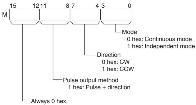
Note Use the same pulse output method when using both pulse outputs 0 and 1.
S: First Word of Settings Table
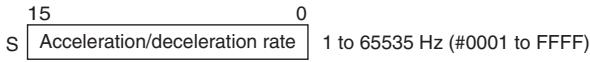
Specify the increase or decrease in the frequency per pulse control period (4 ms).
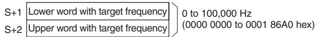
Specify the frequency after acceleration or deceleration in Hz.
- Operand Specifications
| Area | Word addresses | Indirect DM addresses | Constants | CF | Pulse bits | TR bits | |||||||
| CIO | WR | HR | AR | T | C | DM | @DM | *DM | |||||
| P, M | --- | --- | --- | --- | --- | --- | --- | --- | --- | OK | --- | --- | --- |
| S | OK | OK | OK | OK | OK | OK | OK | OK | OK | --- | |||
Flags
| Name | Label | Operation |
| Error Flag | P_ER | ON if the specified range for P, M, or S is exceeded.ON if pulses are being output using ORG(889) for the specified port.ON if ACC(888) is executed to switch between independent and continuous mode for a port that is outputting pulses for SPED(885), ACC(888), or PLS2(887).ON if ACC(888) is executed in an interrupt task when an instruction controlling pulse output is being executed in a cyclic task.ON if ACC(888) is executed for an absolute pulse output in independent mode but the origin has not been established.OFF in all other cases. |
Function
ACC(888) starts pulse output on the port specified in P using the mode specified in M using the target frequency and acceleration/deceleration rate specified in S. The frequency is increased every pulse control period (4 ms) at the acceleration rate specified in S until the target frequency specified in S is reached.
Pulse output is started each time ACC(888) is executed. It is thus normally sufficient to use the differentiated version (@ACC(888)) of the instruction or an execution condition that is turned ON only for one scan.
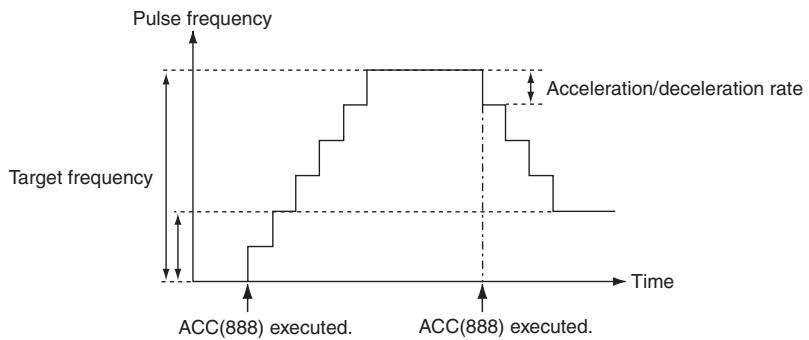
In independent mode, pulse output stops automatically when the specified number of pulses has been output. In continuous mode, pulse output continues until it is stopped from the program.
An error will occur if an attempt is made to switch between independent and continuous mode during pulse output.
PLS2(887) can be executed during pulse output for ACC(888) in either independent or continuous mode, and during acceleration, constant speed, or deceleration. (See note.) ACC(888) can also be executed during pulse output for PLS2(887) during acceleration, constant speed, or deceleration.
If ACC(888) is executed in independent or continuous mode with a target frequency of 0Hz and then ACC(888) or PLS2(887) is executed before pulse output stops, the target frequency will not change and pulse output will stop. Execute ACC(888) or PLS2(887) after pulse output stops.
Note 1 Executing PLS2(887) during speed control with ACC(888) (continuous mode) with the same target frequency as ACC(888) can be used to achieved interrupt feeding of a fixed distance. Acceleration will not be performed by PLS2(887) for this application, but if the acceleration rate is set to 0, the Error Flag will turn ON and PLS2(887) will not be executed. Always set the acceleration rate to a value other than 0.
2 If ACC (888) or PLS2 (887) is executed during the period from pulse output stop to one cycle after the stop (when pulse output in-progress flag is ON), pulse output will start again in the next cycle after stopping. However, if pulse output is stopped by INI (880), the pulse output instruction will become invalid within one cycle after the stop. Execute the instruction till the pulse output in-progress flag is OFF.
3 ACC instruction can be used only with transistor output type of CP1E N/NA-type CPU Unit. In case of transistor output type of CP1E E-type CPU Unit or relay output type, NOP processing is applied.
Continuous Mode Speed Control
Pulse output will continue until it is stopped from the program.
Note Pulse output will stop immediately if the CPU Unit is changed to PROGRAM mode.
| Operation | Purpose | Application | Frequency changes | Description | Procedure/instruction |
| Starting pulse output | To output with speci-fied acceleration and speed | Accelerating the speed (frequency) at a fixed rate | Pulse frequency Target frequency Present frequency Acceleration/ deceleration rate Time Execution of ACC(888) | Outputs pulses and changes the frequency at a fixed rate. | ACC(888) (Continuous) |
| Changing settings | To change speed smoothly | Changing the speed smoothly during operation | Pulse frequency Target frequency Present frequency Acceleration/ deceleration rate Time Execution of ACC(888) | Changes the frequency from the present frequency at a fixed rate. The frequency can be accelerated or decelerated. | ACC(888) or SPED(885) (Continuous) ↓ ACC(888) (Continuous) |
| Changing the speed in a polylne curve during operation | Pulse frequency Target frequency Acceleration rate 2 Acceleration rate 1 Execution of ACC(888) Execution of ACC(888) Execution of ACC(888) | Changes the acceleration or deceleration rate during acceleration or deceleration. | ACC(888) (Continuous) ↓ ACC(888) (Continuous) | ||
| Decelerating to a stop | Pulse frequency Present frequency Target frequency = 0 Execution of ACC(888) Execution of ACC(888) Execution of ACC(888) (target frequency = 0) | The deceleration rate is changed while decelerating. Note If the target frequency is set to 0 Hz, the current deceleration rate will be used. | ACC(888) (Continuous) ↓ ACC(888) (Continuous) ↓ ACC(888) (Continuous, target frequency of 0 Hz) | ||
| Stopping pulse output | To stop pulse output | Immediate stop | Pulse frequency Present frequency Execution of ACC(888) Execution of INI(880) | Immediately stops pulse output. | ACC(888) (Continuous) ↓ INI(880) (Continuous) |
| To stop pulse output smoothly | Decelerating to a stop | Pulse frequency Present frequency Target frequency = 0 Execution of ACC(888) Execution of ACC(888) | Decelerated pulse output to a stop. Note If the target frequency of the second ACC(888) instruction is 0 Hz, the deceleration rate from the first ACC(888) instruction will be used. | ACC(888) (Continuous) ↓ ACC(888) (Continuous, target frequency of 0) |
- Independent Mode Positioning
When independent mode operation is started, pulse output will be continued until the specified number of pulses has been output.
The deceleration point is calculated from the number of output pulses and deceleration rate set in S and when that point is reached, the frequency is decreased every pulse control period (4 ms) at the deceleration rate specified in S until the specified number of points has been output, at which point pulse output is stopped.
Note 1 Pulse output will stop immediately if the CPU Unit is changed to PROGRAM mode.
2 The number of output pulses must be set each time output is restarted.
3 The number of output pulses must be set in advance with PULS(881). Pulses will not be output for ACC(888) if PULS(881) is not executed first.
4 The direction set in the ACC(888) operand will be ignored if the number of pulses is set with PULS(881) as an absolute value.
| Operation | Purpose | Application | Frequency changes | Description | Procedure/instruction |
| Starting pulse output | Simple trap-ezoidal control | Positioning with trapezoidal acceleration and deceleration (Same rate used for acceleration and deceleration; no starting speed) The number of pulses cannot be changed during positioning. | Pulse frequency Specified number of pulses (Specified with PULS(886).) Target frequency Acceleration/ deceleration rate Time Execution of ACC(888) Outputs the specified number of pulses and then stops. | Accelerates and decelerates at the same fixed rate and stops immediately when the specified number of pulses has been output. (See note.) Note The target position (specified number of pulses) cannot be changed during positioning. | PULS(886) ↓ ACC(888) (Independent) |
| Changing settings | To change speed smoothly (with the same acceleration and deceleration rates) | Changing the target speed (frequency) during positioning (acceleration rate = deceleration rate) | Pulse frequency Specified number of pulses (Specified with PULS(886).) Number of pulses specified with PULS(886) does not change. Target frequency Execution of ACC(888) (independent mode) ACC(888) (independent mode) executed again to change the target frequency. (The target position is not changed, but the acceleration/deceleration rate is changed.) | ACC(888) can be executed during positioning to change the acceleration/deceleration rate and target frequency. The target position (specified number of pulses) is not changed. | PULS(886) ↓ ACC(888) or SPED(885) (Independent) ↓ ACC(888) (Independent) PLS2(887) ↓ ACC(888) (Independent) |
| Stopping pulse output | To stop pulse output. (Number of pulses setting is not preserved.) | Immediate stop | Pulse frequency Present frequency Execution of ACC(888) Execution of INI(880) | Pulse output is stopped immediately and the remaining number of outputs is cleared. | PULS(886) ↓ ACC(888) (Independent) ↓ INI(880) |
| Stopping pulse output, continued | To stop pulse output smoothly. (Number of pulses setting is not preserved.) | Decelerating to a stop | Pulse frequency Present frequency Target frequency = 0 Execution of PLS2(887) | Decelerates the pulse output to a stop. Note If ACC(888) started the operation, the original acceleration/deceleration rate will remain in effect. If SPED(885) started the operation, the acceleration / deceleration rate will be invalid and the pulse output will stop immediately. | PULS(886)↓ACC(888) or SPED(885)(Independent)↓ACC(888)(Independent, independent, target frequency of 0) |
| PLS2(887)↓ACC(888)(Independent, target frequency of 0) |
Note Triangular Control
If the specified number of pulses is less than the number required to reach the target frequency and return to zero, the function will automatically reduce the acceleration/deceleration time and perform triangular control (acceleration and deceleration only.) An error will not occur.
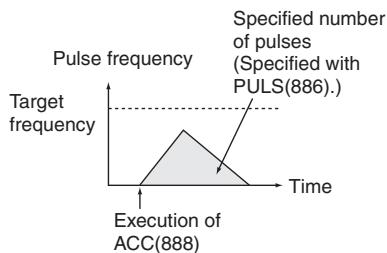
Sample program
When CIO 0.00 turns ON in the following programming example, ACC(888) starts pulse output from pulse output 0 in continuous mode in the clockwise direction using the pulse + direction method. Pulse output is accelerated at a rate of 20Hz every 4 ms until the target frequency of 500Hz is reached. When CIO 0.01 turns ON, ACC(888) changes to an acceleration rate of 10Hz every 4 ms until the target frequency of 1,000Hz is reached.
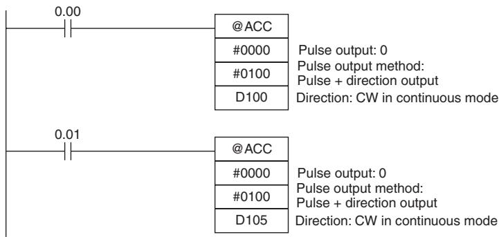
| D100 | 0014 | Acceleration/deceleration rate: 20 Hz |
| D101 | 01F4 | Target frequency: 500 Hz |
| D102 | 0000 | |
| D105 | 000A | Acceleration/deceleration rate: 10 Hz |
| D106 | 03E8 | Target frequency: 1,000 Hz |
| D107 | 0000 |
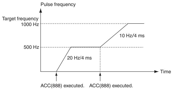
ORG
| Instruction | Mnemonic | Variations | Function code | Function |
| ORIGIN SEARCH | ORG | @ORG | 889 | ORG(889) performs an origin search or origin return operation. |
| Symbol | ORG | |
| — | — | |
| ORG(889) | ||
| P | ||
| C | ||
| P: Port specifier | ||
| C: Control data | ||
Applicable Program Areas
| Area | Step program areas | Subroutines | Interrupt tasks |
| Usage | OK | OK | OK |
Operands
| Operand | Description | Data type | Size |
| P | Port specifier | --- | 1 |
| C | Control data | --- | 1 |
P: Port Specifier
| P | Port |
| 0000 hex | Pulse output 0 |
| 0001 hex | Pulse output 1 |
C: Control Data
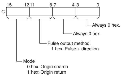
- Operand Specifications
| Area | Word addresses | Indirect DM addresses | Constants | CF | Pulse bits | TR bits | |||||||
| CIO | WR | HR | AR | T | C | DM | @DM | *DM | |||||
| P,C | --- | --- | --- | --- | --- | --- | --- | --- | --- | OK | --- | --- | --- |
Flags
| Name | Label | Operation |
| Error Flag | P_ER | ON if the specified range for P or C is exceeded.ON if ORG(889) is specified for a port during pulse output for SPED(885), ACC(888), or PLS2(887).ON if ORG(889) is executed in an interrupt task when an instruction controlling pulse output is being executed in a cyclic task.ON if the origin search or origin return parameters set in the PLC Setup are not within range.ON if the Origin Search High Speed is less than or equal to the Origin Search Proximity Speed or the Origin Search Proximity Speed is less than or equal to the Origin Search Initial Speed.ON if an origin return operation is attempted when the origin has not been established.OFF in all other cases. |
Function
ORG(889) performs an origin search or origin return operation for the port specified in P using the method specified in C.
The following parameters must be set in the PLC Setup before ORG(889) can be executed.
| Origin search | Origin return |
| • Origin Search Function Enable/Disable • Origin Search Operating Mode • Origin Search Operation Setting • Origin Detection Method • Origin Search Direction Setting • Origin Search/Return Initial Speed • Origin Search High Speed • Origin Search Proximity Speed • Origin Compensation • Origin Search Acceleration Rate • Origin Search Deceleration Rate • Limit Input Signal Type • Origin Proximity Input Signal Type • Origin Input Signal Type • Positioning Monitor Time | • Origin Search/Return Initial Speed • Origin Return Target Speed • Origin Return Acceleration Rate • Origin Return Deceleration Rate |
An origin search or origin return is started each time ORG(889) is executed. It is thus normally sufficient to use the differentiated version (@ORG(889)) of the instruction or an execution condition that is turned ON only for one scan.
Note ORG instruction can be used only with transistor output type of CP1E N/NA-type CPU Unit.
In case of transistor output type of CP1E E-type CPU Unit or relay output type, NOP processing is applied.
- Origin Search (Bits 12 to 15 of C = 0 hex)
ORG(889) starts outputting pulses using the specified method at the Origin Search Initial Speed (1 in diagram).
Pulse output is accelerated to the Origin Search High Speed using the Origin Search Acceleration Rate (2 in diagram).
Pulse output is then continued at constant speed until the Origin Proximity Input Signal turns ON (3 in diagram), from which point pulse output is decelerated to the Origin Search Proximity Speed using the Origin Search Deceleration Rate (4 in diagram).
Pulses are then output at constant speed until the Origin Input Signal turns ON (5 in diagram).
Pulse output is stopped when the Origin Input Signal turns ON (6 in diagram).
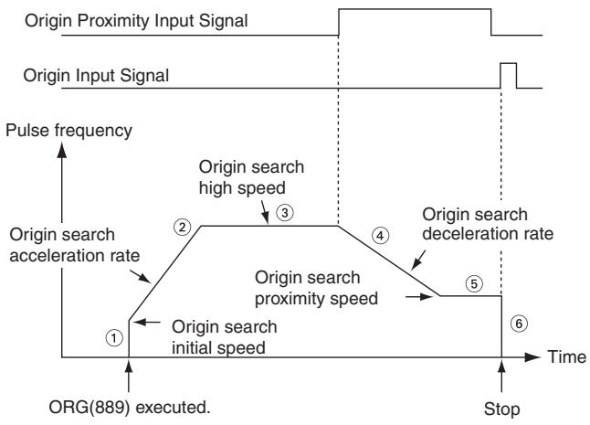
When the origin search operation has been completed, the Error Counter Reset Output will be turned ON.
The above operation, however, depends on the operating mode, origin detection method, and other parameters.
- Origin Return (Bits 12 to 15 of C = 1 hex)
ORG(889) starts outputting pulses using the specified method at the Origin Return Initial Speed (1 in diagram).
Pulse output is accelerated to the Origin Return Target Speed using the Origin Return Acceleration Rate (2 in diagram) and pulse output is continued at constant speed (3 in diagram).
The deceleration point is calculated from the number of pulses remaining to the origin and the deceleration rate and when that point is reached, the pulse output is decelerated (4 in diagram) at the Origin Return Deceleration Rate until the Origin Return Start Speed is reached, at which point pulse output is stopped at the origin (5 in diagram).
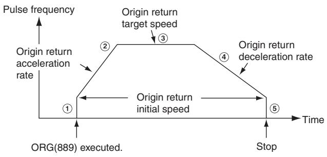
Sample program
When CIO 0.00 turns ON in the following programming example, ORG(889) starts an origin return operation for pulse output 0 by outputting pulses using the pulse + direction method. According to the PLC Setup, the initial speed is 100 pps, the target speed is 200 pps, and the acceleration and deceleration rates are 50Hz / 4 ms.
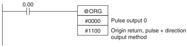
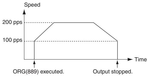
The PLC Setup parameters are as follows:
| Parameter | Setting |
| Pulse Output 0 Starting Speed for Origin Search and Origin Return | 0000 0064 hex: 100 pps |
| Pulse Output 0 Origin Return Target Speed | 0000 00C8 hex: 200 pps |
| Pulse Output 0 Origin Return Acceleration Rate | 0032 hex: 50 hex/4 ms |
| Pulse Output 0 Origin Return Deceleration Rate | 0032 hex: 50 hex/4 ms |
PWM
| Instruction | Mnemonic | Variations | Function code | Function |
| PULSE WITH VARIABLE DUTY FACTOR | PWM | @PWM | 891 | PWM(891) is used to output pulses with the speci-fied duty factor from the specified port. |
| Symbol | PWM | |
| —|—|—|PWM—|—|P: Port specifierF: FrequencyD: Duty factor | ||
| P | P: Port specifier | |
| F | ||
| D | D: Duty factor | |
Applicable Program Areas
| Area | Step program areas | Subroutines | Interrupt tasks |
| Usage | OK | OK | OK |
Operands
| Operand | Description | Data type | Size |
| P | Port specifier | --- | 1 |
| F | Frequency | --- | 1 |
| D | Duty factor | --- | 1 |
P: Port Specifier
| P | Port |
| 1000 hex | PWM output 0 (duty factor: in increments of 1%, frequency 0.1 Hz) |
| 1100 hex | PWM output 0 (duty factor: in increments of 1%, frequency 1 Hz) |
F: Frequency
F specifies the frequency of the PWM output between 2.0 and 6,553.5 Hz (0.1 Hz units, 0014 to FFFF hex), or between 2 and 32,000 Hz (2 Hz units, 0002 to 7D00 hex).
D: Duty Factor
- 0.0% to 100.0% (0.1% units, 0000 to 03E8 hex)
D specifies the duty factor of the PWM output, i.e., the percentage of time that the output is ON.
- Operand Specifications
| Area | Word addresses | Indirect DM addresses | Constants | CF | Pulse bits | TR bits | |||||||
| CIO | WR | HR | AR | T | C | DM | @DM | *DM | |||||
| P | --- | --- | --- | --- | --- | --- | --- | --- | --- | OK | --- | --- | --- |
| F, D | OK | OK | OK | OK | OK | OK | OK | OK | OK | ||||
Flags
| Name | Label | Operation |
| Error Flag | P_ER | ON if the specified range for P, F, or D is exceeded.ON if PWM are being output using ORG(889) for the specified port.ON if PWM(891) is executed in an interrupt task when an instruction controlling PWM output is being executed in a cyclic task.OFF in all other cases. |
Function
PWM(891) outputs the frequency specified in F at the duty factor specified in D from the port specified in P. PWM(891) can be executed during duty-factor PWM output to change the duty factor without stopping PWM output. Any attempts to change the frequency will be ignored.
PWM output is started each time PWM(891) is executed. It is thus normally sufficient to use the differentiated version (@PWM(891)) of the instruction or an execution condition that is turned ON only for one scan.
The PWM output will continue either until INI(880) is executed to stop it (C = 0003 hex: stop PWM output) or until the CPU Unit is switched to PROGRAM mode.
Note PWM instruction can be used only with transistor output type of CP1E N/NA-type CPU Unit.
In case of transistor output type of CP1E E-type CPU Unit or relay output type, NOP processing is applied.
Sample program
When CIO 0.00 turns ON in the following programming example, PWM(891) starts PWM output from PWM output 0 at 200Hz with a duty factor of 50% . When CIO 0.01 turns ON, the duty factor is changed to 25% .
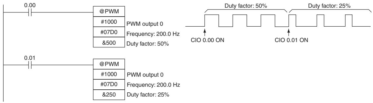
Step Instructions
In CP1E series PLCs, STEP(008)/SNXT(009) can be used together to create step programs.
| Instruction | Operation | Diagram |
| SNXT(009): STEP START | Controls progression to the next step of the program. | Step Ladder section start instruction Equivalent to |
| STEP(008): STEP DEFINE | Indicates the start of a step. Repeats the same step pro-gram until the conditions for progression to the next step are established. | Step Ladder section start instruction Equivalent to Step |
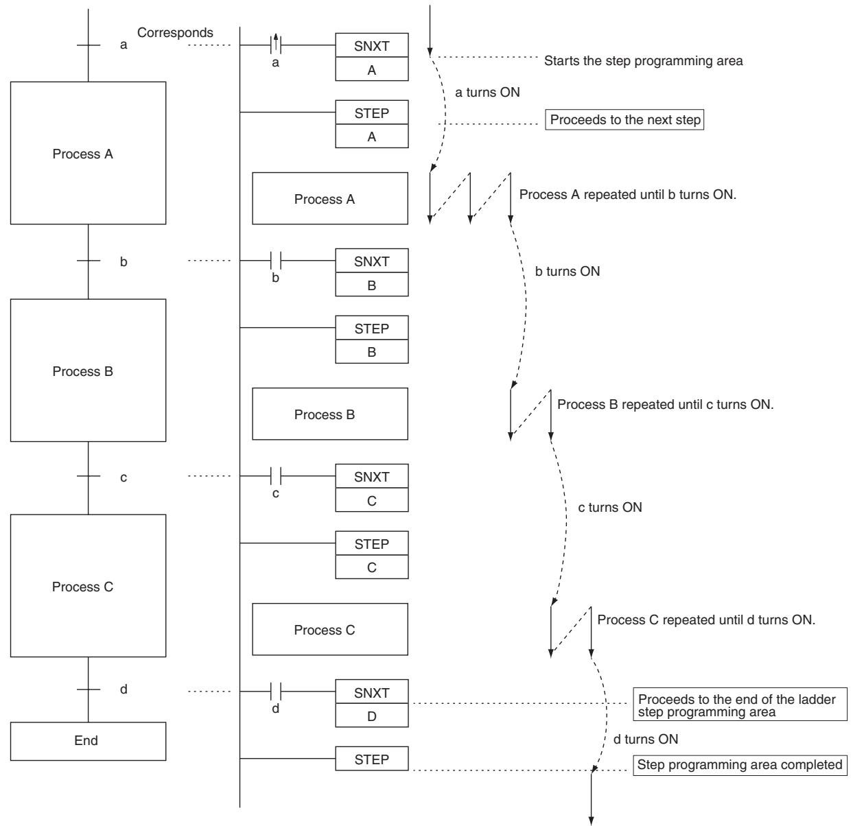
Note Work bits are used as the control bits for A, B, C and D.
SNXT/STEP
| Instruction | Mnemonic | Variations | Function code | Function |
| STEP START | SNXT | --- | 009 | SNXT(009) is used to control progression of step execution in the step program area. |
| STEP DEFINE | STEP | --- | 008 | STEP(008) is used to define the beginning and the end of the step program area. |
| Symbol | SNXT | STEP | |
| SNXT(009)B: Bit | When defining the beginning of a step, a control bit is specified as follows:STEP(008)B: BitWhen defining the end of a step, a control bit is not specified as follows:STEP(008) | When defining the beginning of a step, a control bit is specified as follows:STEP(008)B: BitWhen defining the end of a step, a control bit is not specified as follows:STEP(008) | |
Applicable Program Areas
| Area | Step program areas | Subroutines | Interrupt tasks |
| Usage | OK | Not allowed | Not allowed |
Operands
| Operand | Description | Data type | Size |
| B | Bit | --- | 1 |
- Operand Specifications
| Area | Word addresses | Indirect DM addresses | Constants | CF | Pulse bits | TR bits | |||||||
| CIO | WR | HR | AR | T | C | DM | @DM | *DM | |||||
| B | --- | OK | --- | --- | --- | --- | --- | --- | --- | --- | --- | --- | --- |
Flags
| Name | Label | Operation | |
| SNXT | STEP | ||
| Error Flag | P_ER | ON when the specified bit B is not in the WR area.ON when SNXT(009) is used in an interrupt pro-gram.OFF in all other cases. | ON when the specified bit B is not in the WR area.ON when STEP(008) is used in an interrupt pro-gram.OFF in all other cases. |
Function
SNXT(009)
SNXT(009) is used in the following three ways:
- To start step programming execution.
- To proceed to the next step control bit.
- To end step programming execution.
The step program area is from the first STEP(008) instruction (which always takes a control bit) to the last STEP(008) instruction (which never takes a control bit).
Starting Step Execution
SNXT(009) is placed at the beginning of the step program area to start step execution. It turns ON the control bit specified for B for the next STEP(008) and proceeds to step B (all instructions after STEP(008) B). A differentiated execution condition must be used for the SNXT(009) instruction that starts step programming area execution, or step execution will last for only one cycle.
Proceeding to the Next Step
When SNXT(009) occurs in the middle of the step program area, it is used to proceed to the next step. It turns OFF the previous control bit and turns ON the next control bit B, for the next step, thereby starting step B (all instructions after STEP(008) B).
Ending the Step Programming Area
When SNXT(009) is placed at the very end of the step program area, it ends step execution and turns OFF the previous control bit. The control bit specified for B is a dummy bit. This bit will however be turned ON, so be sure to select a bit that will not cause problems.
- STEP(008)
STEP(008) functions in following 2 ways, depending on its position and whether or not a control bit has been specified.
- Starts a specific step.
- Ends the step program area (i.e., step execution).
Starting a Step
STEP(008) is placed at the beginning of each step with an operand, B, that serves as the control bit for the step.
The control bit B will be turned ON by SNXT(009) and the instruction in the step will be executed from the one immediately following STEP(008). A200.12 (Step Flag) will also turn ON when execution of a step begins.
After the first cycle, step execution will continue until the conditions for changing the step are established, i.e., until the SNXT(009) instruction turns ON the control bit in the next STEP(008).
When SNXT (009) turns ON the control bit for a step, the control bit B of the current instruction will be reset (turned OFF) and the step controlled by bit B will become interlocked.
Handling of outputs and instructions in a step will change according to the ON/OFF status of the control bit B. (The status of the control bit is controlled by SNXT(009)). When control bit B is turned OFF, the instructions in the step are reset and are interlocked. Refer to the following tables.
| Control bit status | Handling |
| ON | Instructions in the step are executed normally. |
| ON→OFF | Bits and instructions in the step are interlocked as shown in the next table. |
| OFF | All instructions in the step are processed as NOPs. |
Interlock Status (IL)
| Instruction output | Status | |
| Bits specified for OUT, OUT NOT | All OFF | |
| TIM, TIMX(551), TIMH(015), TIMHX(551), TMHH(540),TIMHHX(552), TIML(542), and TIMLX(553) | PV | 0000 hex (reset) |
| Completion Flag | OFF (reset) | |
| Bits or words specified for other instructions (see note) | Holds the previous status (but the instructions are not executed) | |
Note Indicates all other instructions, such as TTIM(087), TTIMX(555), SET, REST, CNT, CNTX(546), CNTR(012), CNTRX(548), SFT(010), and KEEP(011).
The STEP(008) instruction must be placed at the beginning of each step. STEP(008) is placed at the beginning of a step area to define the start of the step.
Ending the Step Program Area
STEP(008) is placed at the end of the step program area without an operand to define the end of step programming.
When the control bit preceding a SNXT(009) instruction is turned OFF, step execute is stopped by SNXT(009).
Hint
A200.12 (Step Flag) is turned ON for one cycle when STEP(008) is executed. This flag can be used to conduct initialization once the step execution has started.
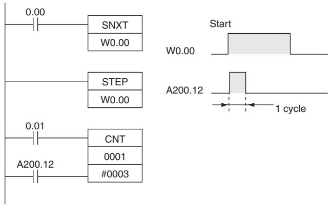
Related Bits
| Name | Address | Details |
| Step Flag | A200.12 | ON for one cycle when a step program is started using STEP(008). Can be used to reset timers and perform other processing when starting a new step. |
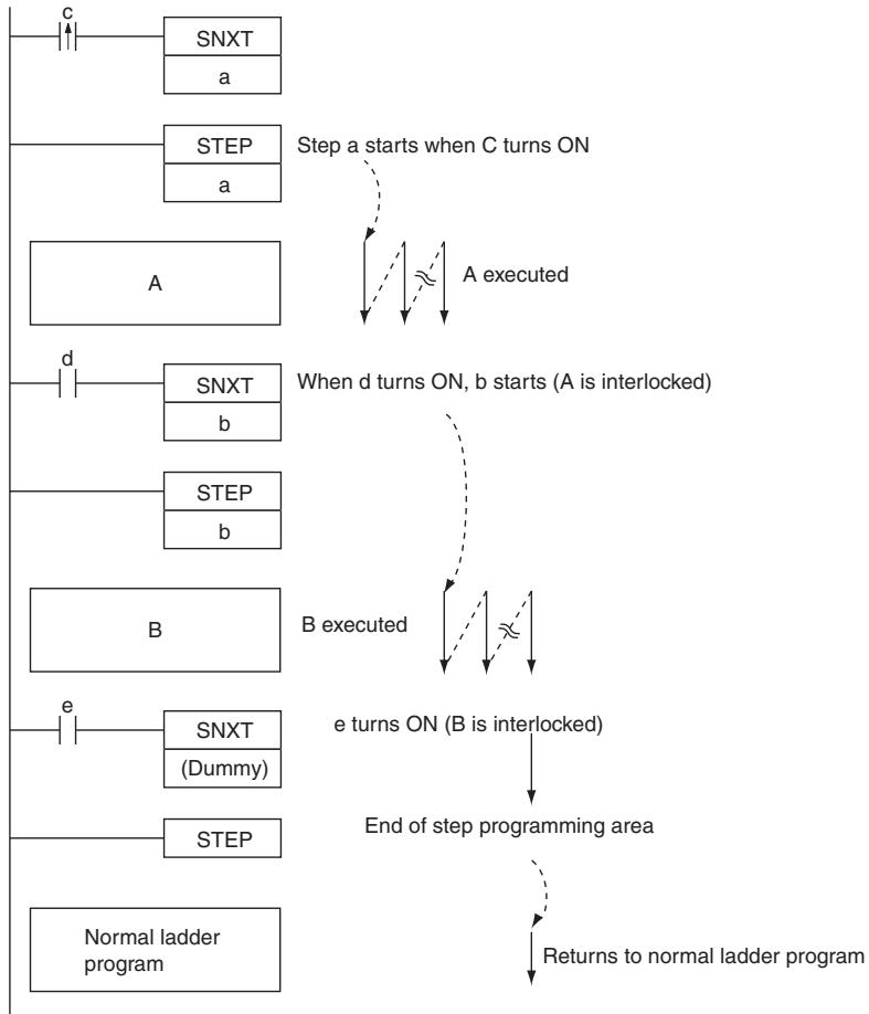
Precaution
- The control bit, B, must be in the Work Area for STEP(008)/SNXT(009).
- A control bit for STEP(008)/SNXT(009) cannot be use anywhere else in the ladder diagram. If the same bit is used twice, as duplication bit error will occur.
- If SBS(091) is used to call a subroutine from within a step, the subroutine outputs and instructions will not be interlocked when the control bit turns OFF.
- SNXT(009) will be executed only once, i.e., on the rising edge of the execution condition.
-
Input SNXT(009) at the end of the step program area and make sure that the control bit is a dummy bit in the Work Area. If a control bit for a step is used in the last SNXT(009) in the step program area, the corresponding step will be started when SNXT(009) is executed.
-
STEP(008) and SNXT(009) cannot be used inside of subroutines, interrupt programs, or block programs.
- Be sure that two steps are not executed during the same cycle.
- The instructions that cannot be used within step programs are listed in the following table.
| Function | Mnemonic | Name |
| Sequence Control Instructions | END(001) | END |
| IL(002) | INTERLOCK | |
| ILC(003) | INTERLOCK CLEAR | |
| JMP(004) | JUMP | |
| JME(005) | JUMP END | |
| CJP(510) | CONDITIONAL JUMP | |
| Subroutine Instructions | SBN(092) | SUBROUTINE ENTRY |
| RET(093) | SUBROUTINE RETURN |
Sample program
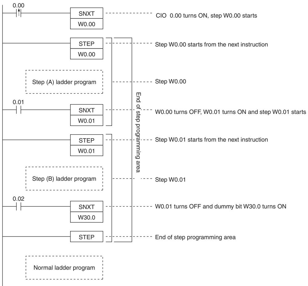
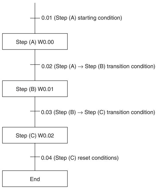
(1) Sequential Control
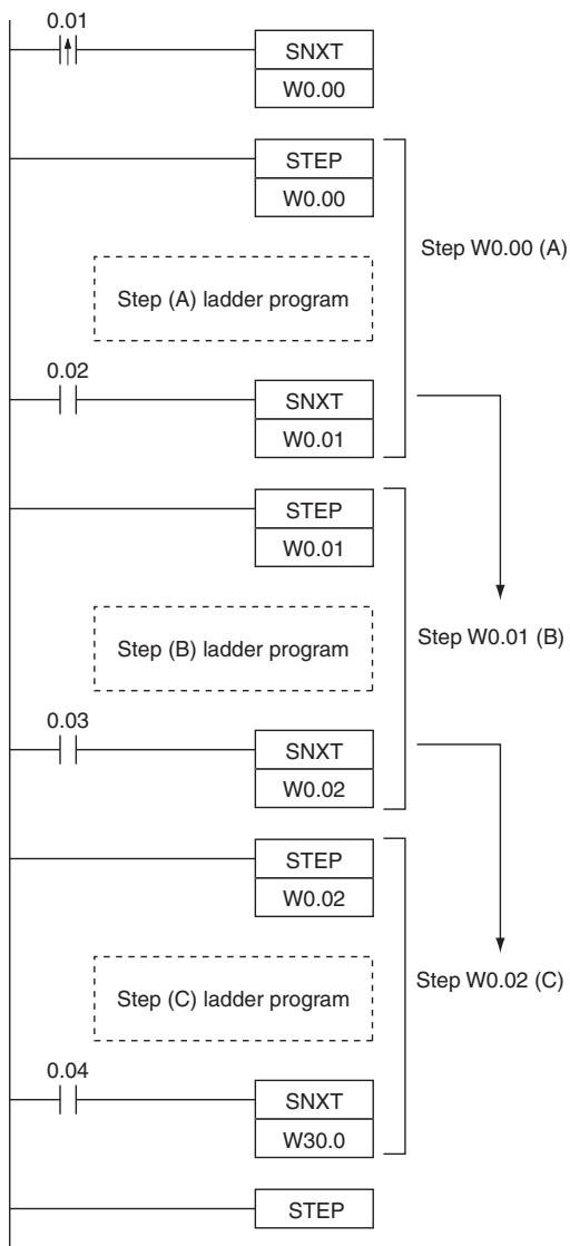
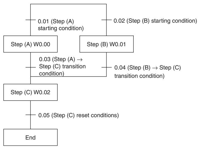
(2) Branching Control
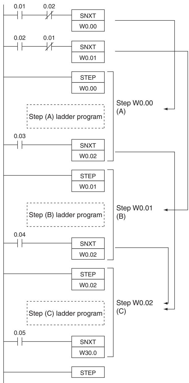
0.02 0.01
一
一
Additional Information:
- In the above example, where SNXT(009) is executed for W0.02, the branching moves onto the next steps even though the same control bit is used twice. This is not picked up as an error in the program check using the CX-Programmer. A duplicate bit error will only occur in a step ladder program only when a control bit in a step instructions is also used in the normal ladder diagram.
- The above programming is used when steps A and B cannot be executed simultaneously. For simultaneous execution of A and B, delete the execution conditions illustrated below.
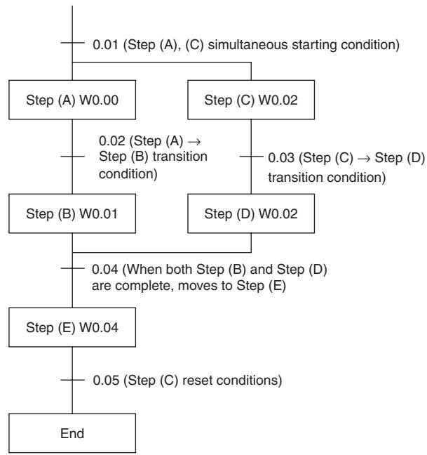
(3) Parallel Control
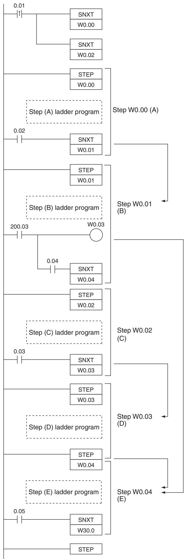
Application Examples
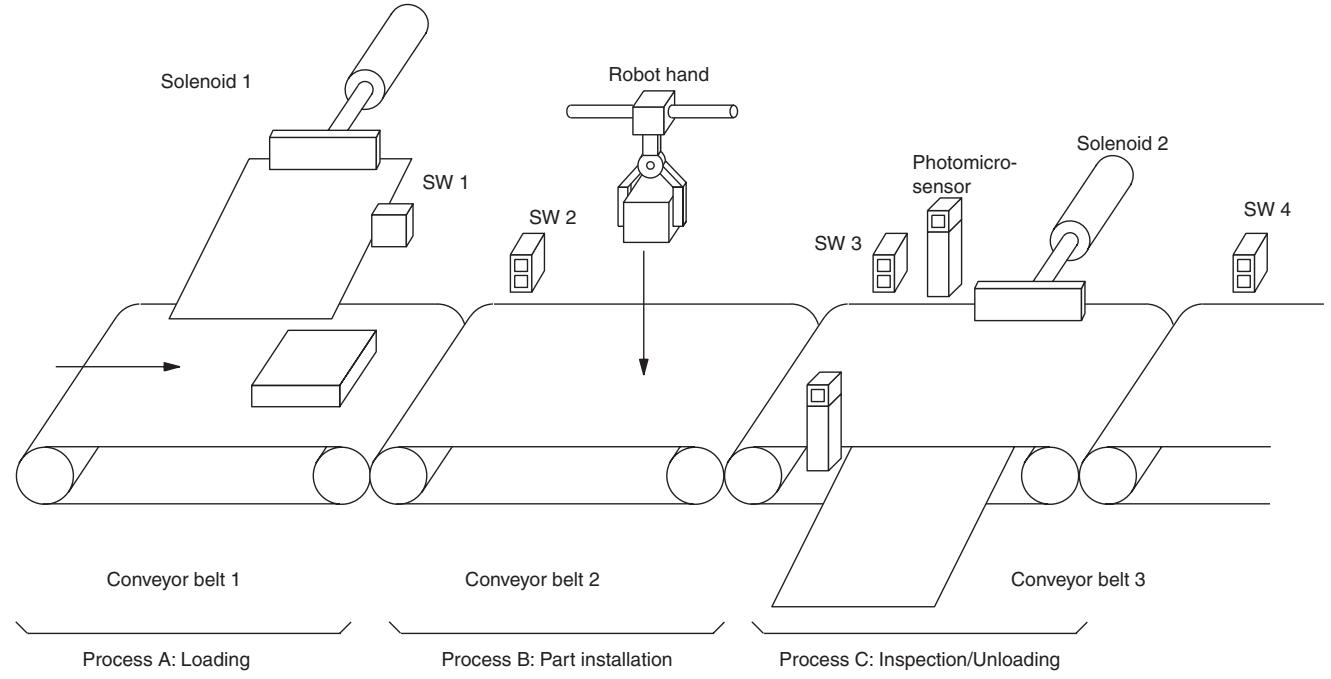
(1) Sequential Execution
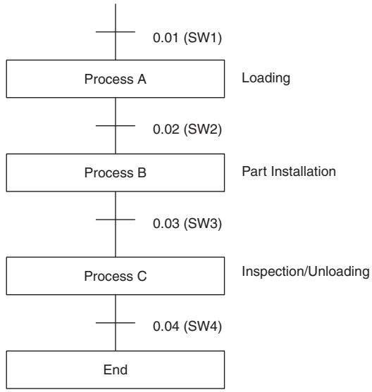
Explanation of operation
(1) SW1 ON:
Solenoid 1 operates
Conveyor 1 operates
(2) SW2 ON stops the previous process
Robot hand operates Process B Conveyor 2 operates
(3) SW3 ON stops the previous process
Photo microsensor operates (for part inspection)
Conveyor 3 operates
Solenoid 2 operates (removal of defective items)
(4) SW4 ON stops the previous process
Additional Information
When another process is started from within a process (when an SNXT instruction turns ON), all outputs of the current process are turned OFF within that cycle.
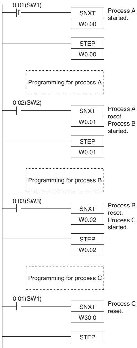
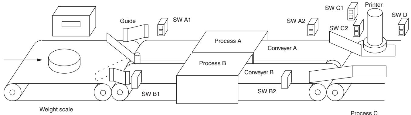
(2) Branching Execution
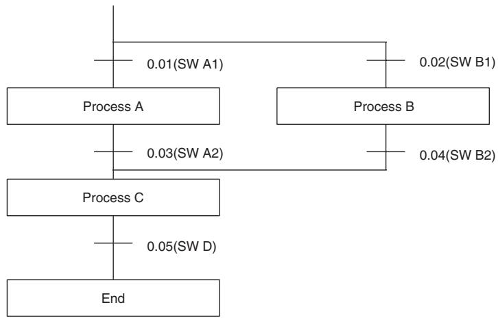
Explanation of operation
Products are sorted by the guides by weight.
(1) SWA1 ON:
Conveyor (A) operates Machine (A) operates
(2) SWB1 ON:
Conveyor (B) operates Machine (B) operates Process B
(3) SWA2 ON stops process A
Printing machine operates (down) Process C UP by SWC2 ON
(4) SWB2 ON stops process B
Printing machine operates (down) Process C UP by SWC2 ON
(5) SWD ON stops the printing machine

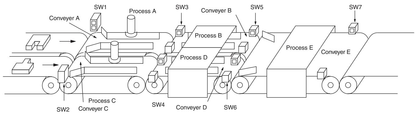
(3) Parallel Execution
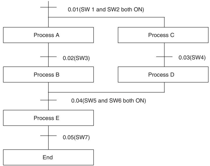
Explanation of operation
(1) SW1, SW2 ON:
Conveyor (A) operates Process A Work (A) operates
Conveyor (C) operates Process C Work (C) operates
(2) SW3 ON:
Process (A) stops Conveyor (B) operates Process B Work (B) operates
(3) SW4 ON:
Process (C) stops Conveyor (D) operates Process D Work (D) operates
(4) SW5, SW6 ON:
Process (B) stops Process (D) stops Conveyor (E) operates Work (E) operates
(5) SW7 ON:
Process (E) stops
Note When processes (B) and (D) are in operation and SW5 and SW6 turn ON, it is judged that processes (B) and (D) are finished. Execution of SNXT W0.04 turns OFF the outputs of process (B) and W0.03 turns OFF. STEP W0.03 judges ON to OFF and turns OFF the outputs of process (D).
Additional Information
The STEP instruction turns all outputs in its process OFF when ON changes to OFF.
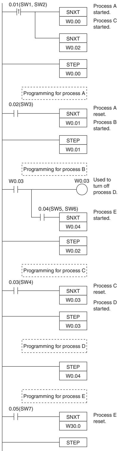
Basic I/O Unit Instructions
IORF
| Instruction | Mnemonic | Variations | Function code | Function |
| I/O REFRESH | IORF | @IORF | 097 | Refreshes the specified I/O words. |
| Symbol | IORF | |
| IORF(097) | St: Starting word | |
| St | E: End word | |
Applicable Program Areas
| Area | Step program areas | Subroutines | Interrupt tasks |
| Usage | OK | OK | OK |
Operands
| Operand | Description | Data type | Size |
| St | Starting word | --- | Variable |
| E | End word | --- | Variable |
St: Starting Word
CIO 001 to CIO 099, CIO 101 to CIO 199 (CP1W Expansion I/O Unit's I/O Area)
E: End Word
CIO 001 to CIO 099, CIO 101 to CIO 199 (CP1W Expansion I/O Unit's I/O Area)
-Operand Specifications
| Area | Word addresses | Indirect DM addresses | Constants | CF | Pulse bits | TR bits | |||||||
| CIO | WR | HR | AR | T | C | DM | @DM | *DM | |||||
| St, E | OK | --- | --- | --- | --- | --- | --- | --- | --- | --- | --- | --- | --- |
Flags
| Name | Label | Operation |
| Error Flag | P_ER | ON if St is greater than E.ON if St and E are in different memory areas.OFF in all other cases. |
Units Refreshed by IORF(097)
| Unit type | CH | Refreshable by IORF(097) |
| CPU Unit with 30 or 40 I/O Points | CP1E CPU Unit built-in I/O: 0CH, 1CH, 100CH and 101CH | No |
| CP1W Expansion I/O Unit: 2CH to 99CH, 102CH to 199CH | Yes | |
| CP1W Expansion Unit: 2CH to 99CH, 102CH to 199CH | Yes | |
| CPU Unit with 60 I/O Points | CP1E CPU Unit built-in I/O: 0CH, 1CH, 2CH, 100CH, 101CH and 102CH | No |
| CP1W Expansion I/O Unit: 3CH to 99CH, 103CH to 199CH | Yes | |
| CP1W Expansion Unit: 3CH to 99CH, 103CH to 199CH | Yes | |
| NA-type CPU Unit | CP1E CPU Unit built-in I/O: 0CH and 100CH | No |
| CP1E CPU Unit built-in analog: 90CH, 91CH and 190CH | Yes | |
| CP1W Expansion I/O Unit: 1CH to 99CH, 101CH to 199CH | Yes | |
| CP1W Expansion Unit: 1CH to 99CH, 101CH to 199CH | Yes |
Note CP1E CPU Unit built-in I/O area cannot be refreshed with IORF(097).
CP1E CPU Unit built-in I/O area can be refreshed with immediate refreshing specifications (!).
Function
IORF(097) refreshes the I/O words between St and E, inclusively. IORF(097) is used to refresh words allocated to CP1W Expansion (I/O) Units. For 30 or 40 I/O Points, Expansion (I/O) Units are allocated words between CIO 002 and CIO 099, CIO102 and CIO199. For 60 I/O Points, Expansion (I/O) Units are allocated words between CIO 003 and CIO 099, CIO103 and CIO199. For NA20 I/O Points, Expansion (I/O) Units are allocated words between CIO 001 and CIO 099, CIO101 and CIO199.
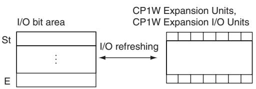
Precaution
- IORF(097) can be used in an interrupt task, which allows high-speed processing of specific I/O data with an interrupt. If IORF(097) is used in an interrupt task, always disable cyclic refreshing of the specified Special I/O Unit by turning ON the corresponding Special I/O Unit Cyclic Refreshing Disable Bit in the PLC Setup.
- If words for which there is no Unit mounted exist between St and E, nothing will be done for those words and only the words allocated to Units will be refreshed.
- The I/O refreshing initiated by IORF(097) will be stopped midway if an I/O bus error occurs during I/O refreshing.
Sample program
Refreshing Words in the I/O Bit Area
When CIO 0.00 turns ON in the following example, CIO 2 to CIO 4 (36 inputs) are refreshed (1) and then after the required processing is performed (2), CIO 104 (8 outputs) is refreshed (3).
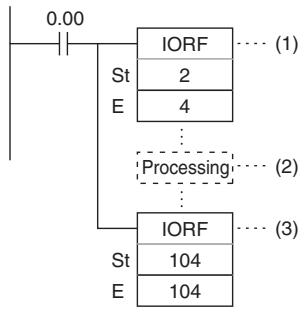
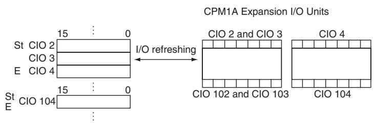
SDEC
| Instruction | Mnemonic | Variations | Function code | Function |
| 7-SEGMENT DECODER | SDEC | @SDEC | 078 | Converts the hexadecimal contents of the designated digit(s) into 8-bit, 7-segment display code and places it into the upper or lower 8-bits of the specified destination words. |
| Symbol | SDEC |
| SDEC(078) | |
| S | |
| Di | |
| D |
Applicable Program Areas
| Area | Step program areas | Subroutines | Interrupt tasks |
| Usage | OK | OK | OK |
Operands
| Operand | Description | Data type | Size |
| S | Source word | UINT | 1 |
| Di | Digit designator | UINT | 1 |
| D | First destination word | UINT | Variable |
Di: Digit designator
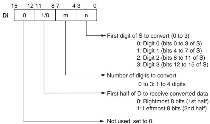
-Operand Specifications
| Area | Word addresses | Indirect DM addresses | Constants | CF | Pulse bits | TR bits | |||||||
| CIO | WR | HR | AR | T | C | DM | @DM | *DM | |||||
| S | OK | OK | OK | OK | OK | OK | OK | OK | OK | --- | --- | --- | --- |
| Di | OK | ||||||||||||
| D | --- | ||||||||||||
Flags
| Name | Label | Operation |
| Error Flag | P_ER | ON if settings in Di are not within the specified ranges. OFF in all other cases. |
Function
SDEC(078) regards the data specified by S as 4-digit hexadecimal data, converts the digits specified in S by Di (first digit and number of digits) to 7-segment data and outputs the results to D in the bits specified in Di.
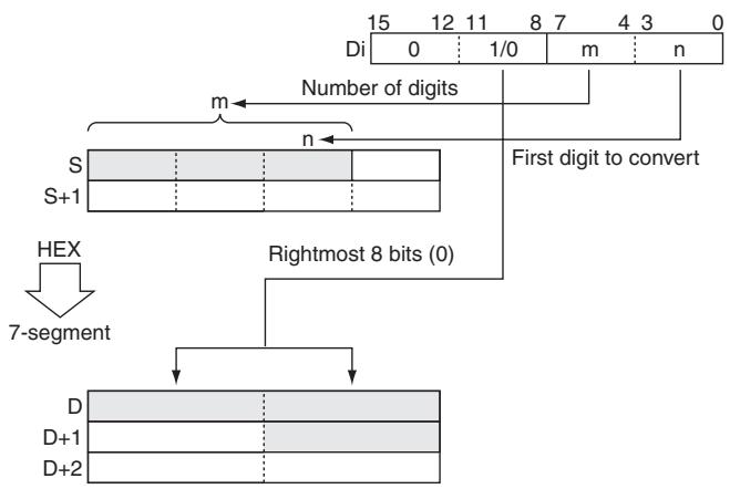
Precaution
- If more than one digit is specified for conversion in Di, digits are converted in order toward the most-significant digit. Digit 0 is the next digit after digit 3.
- Results are stored in D in order from the specified portion toward higher-address words. If just one of the bytes in a destination word receives converted data, the other byte is left unchanged.
Sample program
When CIO 0.00 turns ON in the following example, the contents of the 3 digits beginning with digit 1 in D100 will be converted from hexadecimal data to 7-segment data, and the results will be output to the upper byte of D200 and both bytes of D201. The specifications of the bytes to be converted and the location of the output bytes are made in CIO 100.
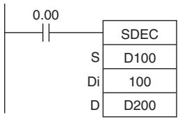
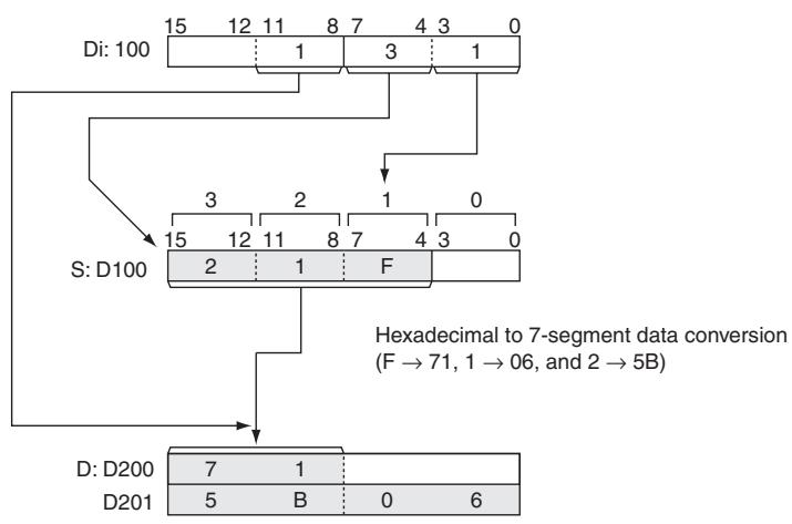
- 7-segment Data
The following table shows the data conversions from a hexadecimal digit (4 bits) to 7-segment code (8 bits).
| Original data | Converted code (segments) | Display Original data | |||||||||||||
| Digit | Bits | - | g | f | e | d | c | b | a | Hex | |||||
| 0 | 0 | 0 | 0 | 0 | 0 | 0 | 1 | 1 | 1 | 1 | 1 | 1 | 3F | 0 | |
| 1 | 0 | 0 | 0 | 1 | 0 | 0 | 0 | 0 | 0 | 1 | 1 | 0 | 06 | 1 | |
| 2 | 0 | 0 | 1 | 0 | 0 | 1 | 0 | 1 | 1 | 0 | 1 | 1 | 5B | 2 | |
| 3 | 0 | 0 | 1 | 1 | 0 | 1 | 0 | 0 | 1 | 1 | 1 | 1 | 4F | 3 | |
| 4 | 0 | 1 | 0 | 0 | 0 | 1 | 1 | 0 | 0 | 1 | 1 | 0 | 66 | 4 | |
| 5 | 0 | 1 | 0 | 1 | 0 | 1 | 1 | 0 | 1 | 1 | 0 | 1 | 6D | 5 | |
| 6 | 0 | 1 | 1 | 0 | 0 | 1 | 1 | 1 | 1 | 1 | 0 | 1 | 7D | 6 | |
| 7 | 0 | 1 | 1 | 1 | 0 | 0 | 1 | 0 | 0 | 1 | 1 | 1 | 27 | 7 | |
| 8 | 1 | 0 | 0 | 0 | 0 | 1 | 1 | 1 | 1 | 1 | 1 | 1 | 7F | 8 | |
| 9 | 1 | 0 | 0 | 1 | 0 | 1 | 1 | 0 | 1 | 1 | 1 | 1 | 6F | 9 | |
| A | 1 | 0 | 1 | 0 | 0 | 1 | 1 | 1 | 0 | 1 | 1 | 1 | 77 | 8 | |
| B | 1 | 0 | 1 | 1 | 0 | 1 | 1 | 1 | 1 | 1 | 0 | 0 | 7C | b | |
| C | 1 | 1 | 0 | 0 | 0 | 0 | 1 | 1 | 1 | 0 | 0 | 1 | 39 | c | |
| D | 1 | 1 | 0 | 1 | 0 | 1 | 0 | 1 | 1 | 1 | 1 | 0 | 5E | d | |
| E | 1 | 1 | 1 | 0 | 0 | 1 | 1 | 1 | 1 | 0 | 0 | 1 | 79 | E | |
| F | 1 | 1 | 1 | 1 | 0 | 1 | 1 | 1 | 0 | 0 | 0 | 1 | 71 | F | |
DSW
| Instruction | Mnemonic | Variations | Function code | Function |
| DIGITAL SWITCH INPUT | DSW | --- | 210 | Reads the value set on a external digital switch (or thumbwheel switch) connected to an I/O Unit and stores the 4-digit or 8-digit value in the specified words. |
| Symbol | DSW | |
| — | — | DSW(210) — | |
| I | I: Input word | ||
| O | O: Output word | ||
| D | D: First result word | ||
| C1 | C1: Number of digits | ||
| C2 | C2: System word | ||
Applicable Program Areas
| Area | Step program areas | Subroutines | Interrupt tasks |
| Usage | OK | OK | Not allowed |
Operands
| Operand | Description | Data type | Size |
| I | Input word | UINT | 1 |
| O | Output word | UINT | 1 |
| D | First result word | WORD | Variable |
| C1 | Number of digit | UINT | 1 |
| C2 | System word | WORD | 1 |
I: Input Word (Data Line D0 to D3 Inputs)
Specify the input word allocated to the Input Unit and connect the digital switch's D0 to D3 data lines to the Input Unit as shown in the following diagram.
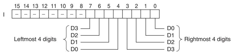
O: Output Word (CS/RD Control Signal Outputs)
Specify the output word allocated to the Output Unit and connect the digital switch's control signals (CS and RD signals) to the Output Unit as shown in the following diagram.
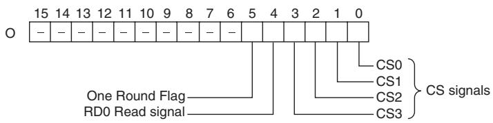
D: First Result Word
Specifies the leading word address where the external digital switch's set values will be stored.
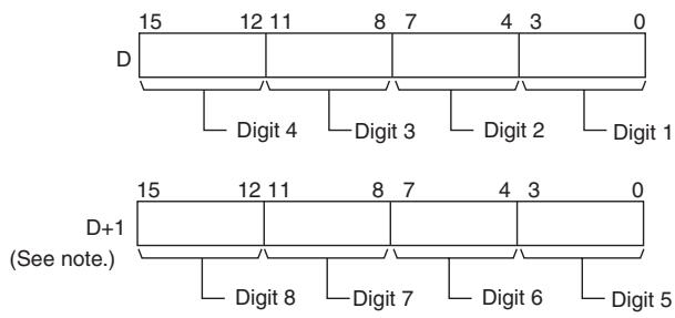
Note: Only when C1 = 0001 hex to read 8 digits.
C1: Number of Digits
- Specifies the number of digits that will be read from the external digital switch. Set C1 to 0000 hex to read 4 digits or 0001 hex to read 8 digits.
C2: System Word
Specifies a work word used by the instruction. This word cannot be used in any other application.
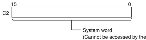
-Operand Specifications
| Area | Word addresses | Indirect DM addresses | Constants | CF | Pulse bits | TR bits | |||||||
| CIO | WR | HR | AR | T | C | DM | @DM | *DM | |||||
| I, O, D | OK | OK | OK | OK | OK | OK | OK | OK | OK | --- | --- | --- | --- |
| C1 | --- | --- | --- | --- | --- | --- | --- | --- | --- | OK | |||
| C2 | OK | OK | OK | OK | OK | OK | OK | OK | --- | ||||
Flags
| Name | Label | Operation |
| Error Flag | P_ER | OFF |
Function
DSW(210) outputs control signals to bits 00 to 04 of O, reads the specified number of digits (either 4-digit or 8-digit, specified in C1) of digital switch data line data from I, and stores the result in D and D+1. (If 4 digits are read, the result is stored in D. If 8 digits are read, the result is stored in D and D+1.)
DSW(210) reads the 4-digit or 8-digit switch data once every 16 cycles, and then starts over and continues reading the data. The One Round Flag (bit 05 of O) is turned ON once every 16 CPU Unit cycles.
- External Connections
Connect the digital switch or thumbwheel switch to Input Unit contacts 0 to 7 and Output Unit contacts 0 to 4, as shown in the following diagram. The following example illustrates connections for an A7B Thumbwheel Switch.
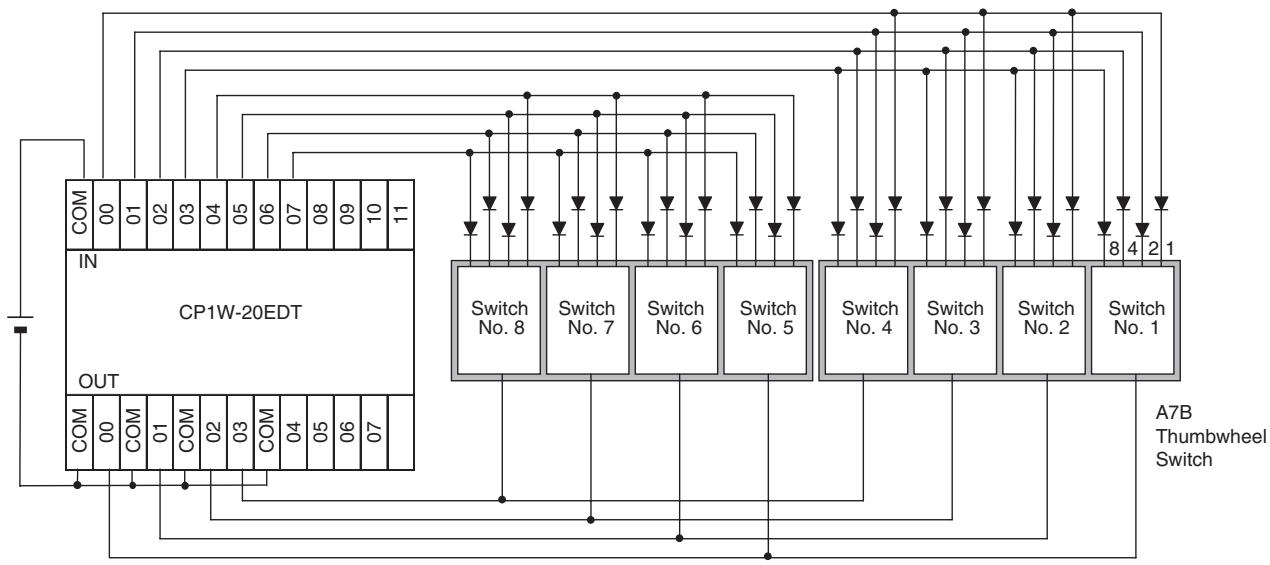
- Timing Chart
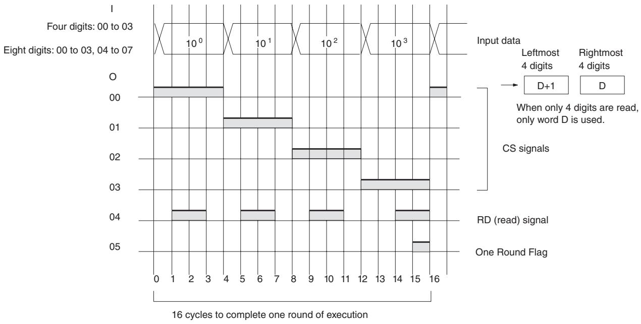
Precaution
- Do not read or write the system word (C2) from any other instruction. DSW(210) will not operate correctly if the system word is accessed by another instruction. The system word is not initialized by DSW(210) in the first cycle when program execution starts. If DSW(210) is being used from the first cycle, clear the system word from the program.
- DSW(210) will not operate correctly if I/O refreshing is not performed with the Input Unit and Output Unit connected to the digital switch or thumbwheel switch after DSW(210) is executed. Consequently, set the input time constant for the Input Units used for the data line input word to a value that is shorter than the cycle time.
- DSW(210) reads the 4-digit or 8-digit data once in 16 cycles, and then starts over and reads the data again in the next 16 cycles.
- When executed, DSW(210) begins reading the switch data from the first of the sixteen cycles, regardless of the point at which the last instruction was stopped.
Sample program
In this example, DSW(210) is used to read an 8-digit number from a digital switch and outputs the resulting value constantly to D0 and D3. The digital switch is connected through CIO 3 and CIO 104.
D1000 is used as the system word.
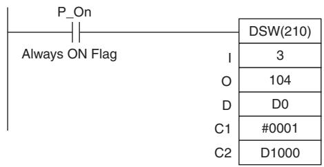
MTR
| Instruction | Mnemonic | Variations | Function code | Function |
| MATRIX INPUT | MTR | --- | 213 | Inputs up to 64 signals from an 8 × 8 matrix con- nected to an Input Unit and an Output Unit (using 8 input points and 8 output points) and stores that 64-bit data in the 4 destination words. |
| Symbol | MTR |
| MTR(213) | |
| I | |
| O | |
| D | |
| C |
Applicable Program Areas
| Area | Step program areas | Subroutines | Interrupt tasks |
| Usage | OK | OK | Not allowed |
Operands
| Operand | Description | Data type | Size |
| I | Input word | UINT | 1 |
| O | Output word | UINT | 1 |
| D | First destination word | ULINT | 4 |
| C | System word | WORD | 1 |
I: Input Word
Specify the input word allocated to the Input Unit and connect the 8 input signal lines to the Input Unit as shown in the following diagram.
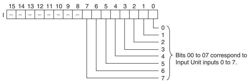
O: Output Word (Selection Signal Outputs)
Specify the output word allocated to the Output Unit and connect the 8 selection signals to the Output Unit as shown in the following diagram.
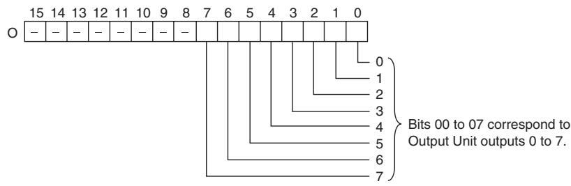
D: First Register Word
Specifies the leading word address of the 4 words that contain the data from the 8 × 8 matrix.
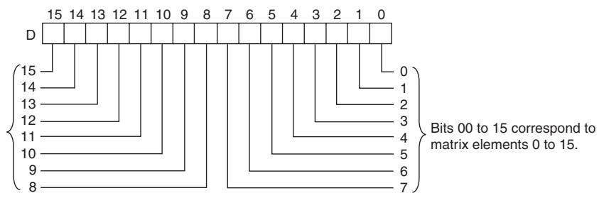

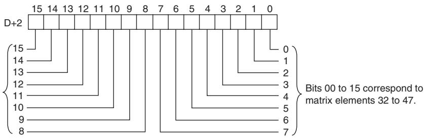
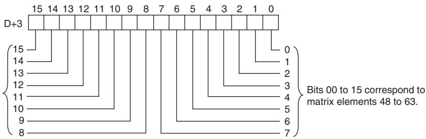
C: System Word
Specifies a work word used by the instruction. This word cannot be used in any other application.
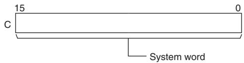
(Cannot be accessed by the user.)
- Operand Specifications
| Area | Word addresses | Indirect DM addresses | Constants | CF | Pulse bits | TR bits | |||||||
| CIO | WR | HR | AR | T | C | DM | @DM | *DM | |||||
| I, O, D, C | OK | OK | OK | OK | OK | OK | OK | OK | OK | --- | --- | --- | --- |
Flags
| Name | Label | Operation |
| Error Flag | P_ER | OFF |
Function
MTR(213) outputs the selection signals to bits 00 to 07 of O, reads the data in order from bits 00 to 07 of I, and stores the 64 bits of data in the 4 words D through D+3. MTR(213) reads the status of the 64-bit matrix every 24 CPU Unit cycles. The One Round Flag (bit 08 of O) is turned ON for one cycle in every 24 cycles after each of the selection signals has been turned ON.
- External Connections
Connect the hexadecimal keypad to Input Unit contacts 0 to 7 and Output Unit contacts 0 to 7, as shown in the following diagram.
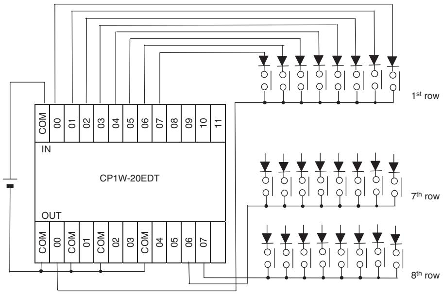
- Timing Chart
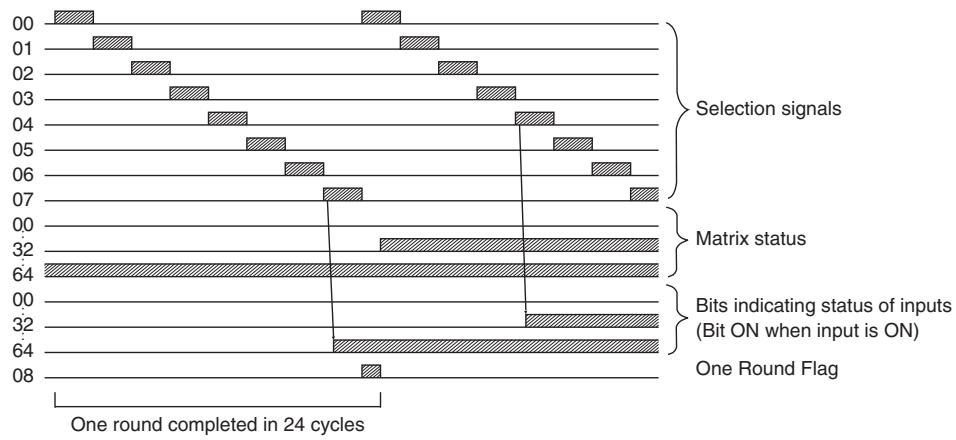
Precaution
- Do not read or write the system word (C) from any other instruction. MTR(213) will not operate correctly if the system word is accessed by another instruction. The system word is not initialized by MTR(213) in the first cycle when program execution starts. If MTR(213) is being used from the first cycle, clear the system word from the program.
- MTR(213) will not operate correctly if I/O refreshing is not performed with the Input Unit and Output Unit connected to the external matrix after MTR(213) is executed. Consequently, set the input time constant for the Input Units used for the data line input word to a value that is shorter than the cycle time.
- When executed, MTR(213) begins reading the matrix status from the beginning of the matrix, regardless of the point at which the last instruction was stopped.
Sample program
In this example, MTR(213) reads the 64 bits of data from the 8 × 8 matrix and stores the data in W0 to W3. The 8 × 8 matrix is connected through CIO 3 and CIO 104. D1000 is used as the system word.
| P_On | |
| Always ON Flag | MTR(213) |
| 3 | |
| 104 | |
| W0 | |
| D1000 | |
7SEG
| Instruction | Mnemonic | Variations | Function code | Function |
| 7-SEGMENT DISPLAY OUTPUT | 7SEG | --- | 214 | Converts the source data (either 4-digit or 8-digit BCD) to 7-segment display data, and outputs that data to the specified output word. |
| Symbol | 7SEG |
| 7SEG(214) | |
| S | |
| O | |
| C | |
| D |
Applicable Program Areas
| Area | Step program areas | Subroutines | Interrupt tasks |
| Usage | OK | OK | Not allowed |
Operands
| Operand | Description | Data type | Size |
| S | Source word | WORD | Variable |
| O | Output word | UINT | 1 |
| C | Control word | #+10 decimal only | 1 |
| D | System word | WORD | 1 |
S: Source Word
Specify the first source word containing the data that will be converted to 7-segment display data.
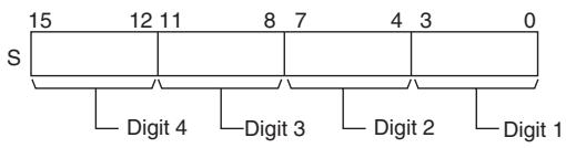
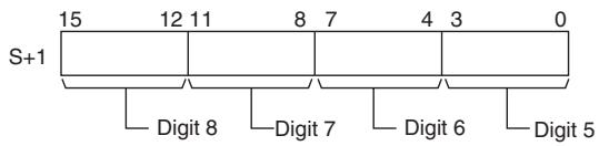
O: Output Word (Data and Latch Outputs)
Specify the output word allocated to the Output Unit and connect the 7-segment display to the Output Unit as shown in the following diagram.
- Converting 4 digits
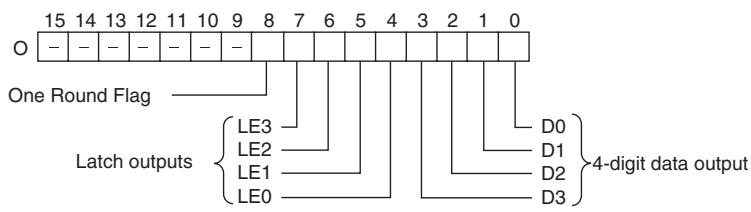
- Converting 8 digits
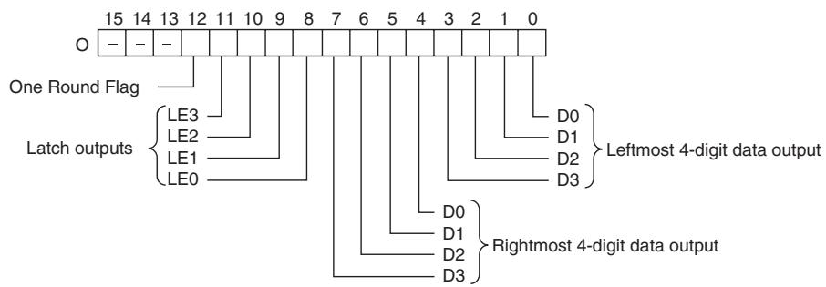
C: Control Data
The value of C indicates the number of digits of source data and the logic for the Input and Output Units, as shown in the following table. (The logic refers to the transistor output's NPN or PNP logic.)
| Source data | Display's data input logic | Display's latch input logic | C |
| 4 digits (S) | Same as Output Unit | Same as Output Unit | 0000 |
| Different from Output Unit | 0001 | ||
| Different from Output Unit | Same as Output Unit | 0002 | |
| Different from Output Unit | 0003 | ||
| 8 digits (S, S+1) | Same as Output Unit | Same as Output Unit | 0004 |
| Different from Output Unit | 0005 | ||
| Different from Output Unit | Same as Output Unit | 0006 | |
| Different from Output Unit | 0007 |
D: System Word
Specifies a work word used by the instruction. This word cannot be used in any other application.
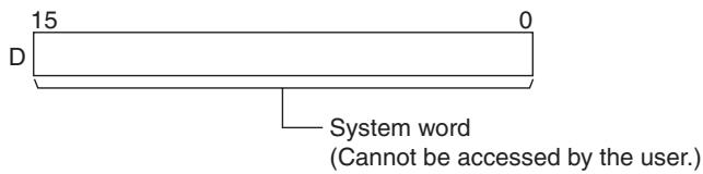
-Operand Specifications
| Area | Word addresses | Indirect DM addresses | Constants | CF | Pulse bits | TR bits | |||||||
| CIO | WR | HR | AR | T | C | DM | @DM | *DM | |||||
| S, O | OK | OK | OK | OK | OK | OK | OK | OK | OK | --- | --- | --- | --- |
| C | --- | --- | --- | --- | --- | --- | --- | --- | --- | OK | |||
| D | OK | OK | OK | OK | OK | OK | OK | OK | OK | --- | |||
Flags
| Name | Label | Operation |
| Error Flag | P_ER | OFF |
Function
7SEG(214) reads the source data, converts it to 7-segment display data, and outputs that data (as leftmost 4 digits D0 to D3, rightmost 4 digits D0 to D3, latch output signals LE0 to LE3) to the 7-segment display connected to the output indicated by O. The value of C indicates the number of digits of source data (either 4-digit or 8-digit) and the logic for the Input and Output Units.
7SEG(214) displays the 4-digit or 8-digit data in 12 cycles, and then starts over and continues displaying the data.
The One Round Flag (bit 08 of O when converting 4 digits, bit 12 of O when converting 8 digits) is turned ON for one cycle in every 12 cycles after 7SEG(214) has turned ON each of the latch output signals.
- External Connections
Connect the 7-segment display to the Output Unit as shown in the following diagram. This example shows an 8-digit display. With a 4-digit display, the data outputs (D0 to D3) would be connected to outputs 0 to 3 and the latch outputs (LE0 to LE3) would be connected to outputs 4 to 7. Output point 12 (for 8-digit display) or output point 8 (for 4-digit display) will be turned ON when one round of data has been output, but it is not necessary to connect them unless required by the application.
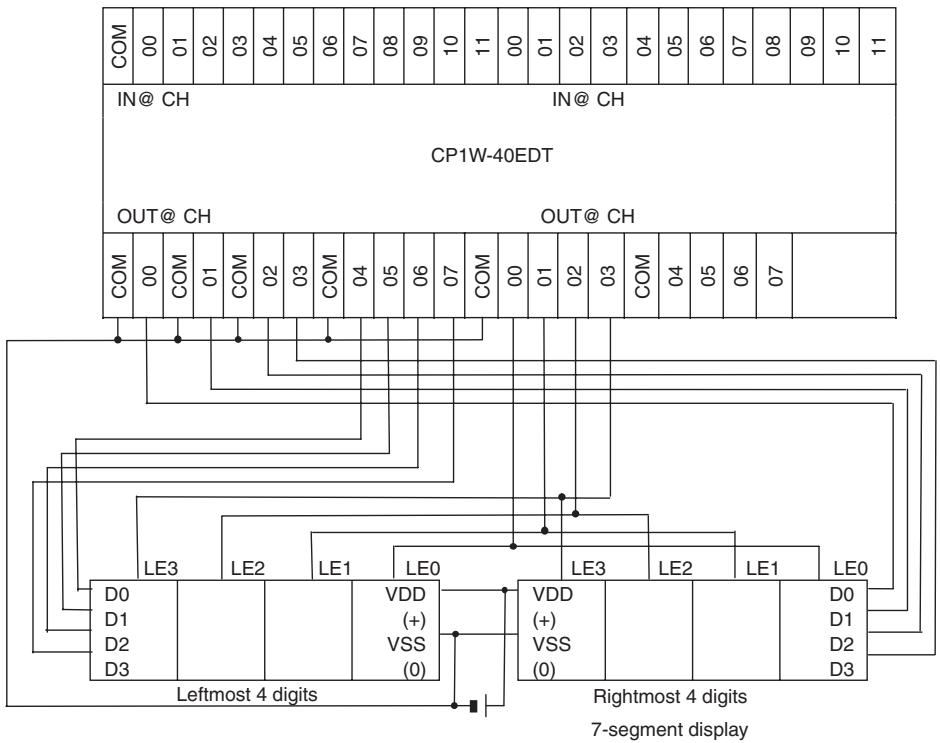
- Timing Chart
| Function | Bit(s) in O | Output status (Data and latch logic depends on C) | ||||||||||
| (4 digits, 1 block) | (4 digits, 2 blocks) | |||||||||||
| Data output | 00 to 03 | 00 to 03 | ||||||||||
| 04 to 07 | 100 | 101 | 102 | 103 | ||||||||
| Latch output 0 | 04 | 08 | ||||||||||
| Latch output 1 | 05 | 09 | ||||||||||
| Latch output 2 | 06 | 10 | ||||||||||
| Latch output 3 | 07 | 11 | ||||||||||
| One Round Flag | 08 | 12 | ||||||||||
| 12 cycles required to complete one round | ||||||||||||
Precaution
- Do not read or write the system word (D) from any other instruction. 7SEG(214) will not operate correctly if the system word is accessed by another instruction. The system word is not initialized by 7SEG(214) in the first cycle when program execution starts. If 7SEG(214) is being used from the first cycle, clear the system word from the program.
- After the 7-segment data is output in 12 cycles, 7SEG(214) starts over and converts the present contents of the source word(s) in the next 12 cycles.
- When executed, 7SEG(214) begins on latch output 0 at the beginning of the round, regardless of the point at which the last instruction was stopped.
- Even if the connected 7-segment display has fewer than 4 digits or 8 digits in its display, 7SEG(214) will still output 4 digits or 8 digits of data.
Sample program
In this example, 7SEG(214) converts the 8 digits of BCD data in D100 and D101 and outputs the data through CIO 100.
There are 8 digits of data being output and the 7-segment display's logic is the same as the Output Unit's logic, so the control data (C) is set to 4. D200 is used as the system word, D.
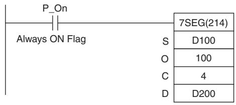
Serial Communication Instructions
TXD
| Instruction | Mnemonic | Variations | Function code | Function |
| TRANSMIT | TXD | @TXD | 236 | Outputs the specified number of bytes of data from the CPU Unit's built-in RS-232C port or the Serial Option Board port. |
| Symbol | TXD | |
| TXD(236) | S: First source word | |
| S | C: Control word | |
| C | N: Number of bytes 0000 to 0100 hex (0 to 256) | |
Applicable Program Areas
| Area | Step program areas | Subroutines | Interrupt tasks |
| Usage | OK | OK | OK |
Operands
| Operand | Description | Data type | Size |
| S | First source word | UINT | Variable |
| C | Control word | UINT | 1 |
| N | Number of bytes 0000 to 0100 hex (0 to 256) | UINT | 1 |
C: Control word
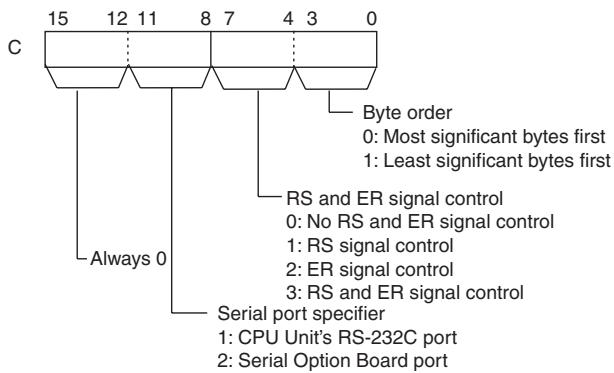
-Operand Specifications
| Area | Word addresses | Indirect DM addresses | Constants | CF | Pulse bits | TR bits | |||||||
| CIO | WR | HR | AR | T | C | DM | @DM | *DM | |||||
| S | OK | OK | OK | OK | OK | OK | OK | OK | OK | --- | --- | --- | --- |
| C, N | OK | ||||||||||||
Flags
| Name | Label | Operation |
| Error Flag | P_ER | ON if no-protocol mode is not set in the PLC Setup.ON if the value of C is not within range.ON if the value for N is not between 0000 and 0100 hex.ON if a send is attempted when the Send Ready Flag is OFF. (The Send Ready Flag is A392.05 for the CPU Unit's RS-232C port, or A392.13 for Serial Option Board port.)OFF in all other cases. |
Related Auxiliary Area Words and Bits
CPU Unit's Built-in RS-232C Port
| Port | Address | Contents |
| CPU Unit's built-in RS-232C port | A392.05 | ON when data can be sent in the no-protocol mode. |
- Serial Option Board Port
| Port | Address | Contents |
| Serial Option Board port | A392.13 | ON when data can be sent in the no-protocol mode. |
Related PLC Setup Settings
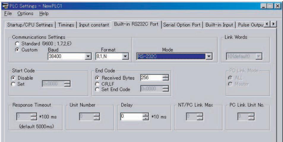
Function
TXD(236) reads N bytes of data from words S to S + (N ÷ 2) - 1 and outputs the raw data in no-protocol mode from the CPU Unit's built-in RS-232C port or the Serial Option Board port. (The output port is specified with bits 8 to 11 of C.)
- The following send-message frame format can be set in the PLC Setup.
1) Start code: None or 00 to FF hex.
2) End code: None, CR+LF, or 00 to FF hex.
The data will be sent with any start and/or end codes specified in the PLC Setup. If start and end codes are specified, the codes will be added to the send data (N). In this case, the maximum number of bytes that can be specified for N is 256 bytes.
Data is sent in the order specified in C0 to C3.
- Specification of control in C4 to C7 for the RS and ER signals take effect as follows:
1) If RS signal control is specified in C, bit 15 of S will be used as the RS signal.
2) If ER signal control is specified in C, bit 15 of S will be used as the ER signal.
3) If RS and ER signal control is specified in C, bit 15 of S will be used as the RS signal and bit 14 of S will be used as the ER signal.
-
If 1, 2, or 3 hex is specified for RS and ER signal control in C, TXD(236) will be executed regardless of the status of the Send Ready Flag (A392.05, or A392.13 depending on the port being used).
-
Up to 259 bytes can be sent, including the send data (N = 256 bytes max.), the start code, and the end code.
- Specify the size of the send data, not including the start code and end code, in N.
- Start code / end code settings and send data
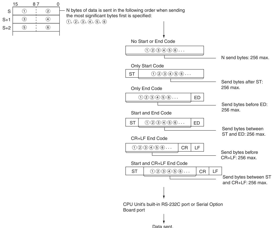
Hint
- When sending data to another device by TXD instruction, the device may require that the data be sent at certain intervals. In that case, a transmission delay time can be set to adjust the transmission intervals.
Precautions
- TXD(236) can be used only for the CPU Unit's RS-232C port or the Serial Option Board port. In addition, the port must be set to no-protocol mode.
- Data can be sent only when the port's Send Ready Flag is ON. (The Send Ready Flag is A392.05 for the CPU Unit's RS-232C port, or A392.13 for Serial Option Board port.)
- Nothing will be sent if 0 is specified for N.
Sample program
- Sending Data to a Code Reader
This example shows how to send data to the V530-R150V3 2D Code Reader as an example of communicating with an external device.
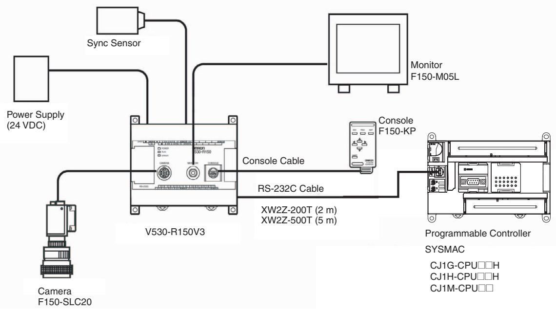
Hardware Configuration
In this example, the external device is connected to the RS-232C port built into the CPU Unit.
First, set the reading conditions for the Code Reader.
Communications Settings
The communications settings of the Code Reader are given in the following table. These are the default settings.
| Item | Setting |
| Communications mode | No-protocol |
| Baud rate | 38,400 bps |
| Data bit length | 8 bits |
| Parity | None |
| Stop bits | 1 |
| Start code | None |
| End code | #000D (CR) |
Set the PLC communications settings to the same values in the PLC Setup. Only the end code needs to be set.
Programming Example
If CIO 0.01 turns ON while the RS-232C Port Send Ready Flag (A392.05) is ON, three bytes of data starting from the upper byte of D10 are sent without conversion to the Code Reader connected to the CPU Unit's built-in RS-232C port. These three bytes contain "@GO", which is the normal read command used as a trigger input to the Code Reader from the RS-232C line.
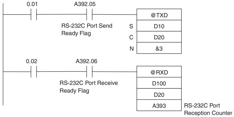
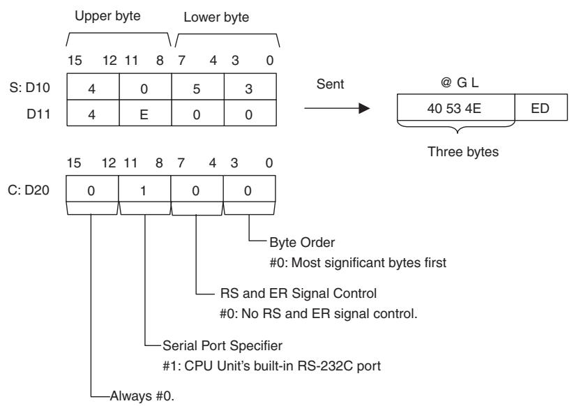
- Controlling Signals
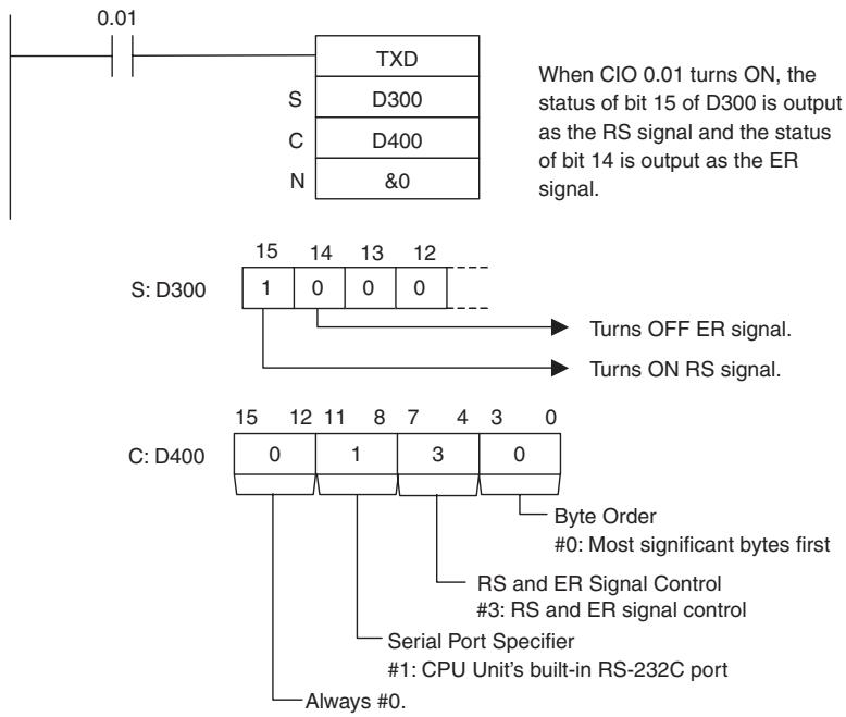
RXD
| Instruction | Mnemonic | Variations | Function code | Function |
| RECEIVE | RXD | @RXD | 235 | Reads the specified number of bytes of data from the CPU Unit's built-in RS-232C port or the Serial Option Board port. |
| Symbol | RXD |
| RXD(235) | |
| D | |
| C | |
| N | |
| N: Number of bytes to store 0000 to 0100 hex (0 to 256 decimal) |
Applicable Program Areas
| Area | Step program areas | Subroutines | Interrupt tasks |
| Usage | OK | OK | OK |
Operands
| Operand | Description | Data type | Size |
| D | First destination word | UINT | Variable |
| C | Control word | UINT | 1 |
| N | Number of bytes to store 0000 to 0100 hex (0 to 256 decimal) | UINT | 1 |
C: Control Word
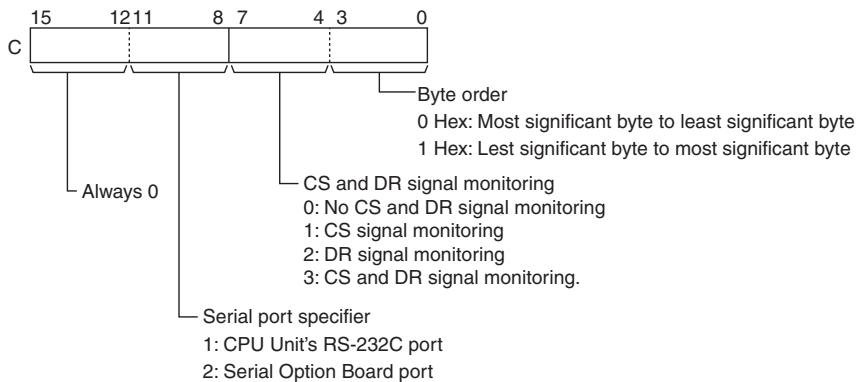
-Operand Specifications
| Area | Word addresses | Indirect DM addresses | Constants | CF | Pulse bits | TR bits | |||||||
| CIO | WR | HR | AR | T | C | DM | @DM | *DM | |||||
| D | OK | OK | OK | OK | OK | OK | OK | OK | OK | --- | --- | --- | --- |
| C, N | OK | ||||||||||||
Flags
| Name | Label | Operation |
| Error Flag | P_ER | ON if no-protocol mode is not set in the PLC Setup.ON if the value of C is not within range.ON if the value for N is not between 0000 and 0100 hex.OFF in all other cases. |
Related Auxiliary Area Words and Bits
- Auxiliary Area Flags for CPU Unit's RS-232C Port
| Name | Address | Contents |
| RS-232C Port Reception Completed Flag | A392.06 | ON when no-protocol reception is completed.Number of Receive Bytes Specified: The flag will turn ON when the specified number of bytes has been received.End Code Specified: The flag will turn ON when the end code is received or when 256 bytes have been received. |
| RS-232C Port Reception Overflow Flag | A392.07 | ON when more than the expected number of receive bytes has been received.Number of Receive Bytes Specified: The flag will turn ON when anything is received after reception has been completed and execution of the next RXD(235).End Code Specified: The flag will turn ON when anything is received after the end code has been received and execution of the next RXD(235) or when the 257th byte of data is received before the end code is received. |
| RS-232C Port Reception Counter | A393 | Counts in hexadecimal the number of bytes received in no-protocol mode (0 to 256 decimal). |
- Auxiliary Area Flags for Serial Option Board Port
| Name | Address | Contents |
| Serial Option Board port Reception Completed Flag | A392.14 | ON when no-protocol reception is completed.Number of Receive Bytes Specified: The flag will turn ON when the specified num ber of bytes has been received.End Code Specified: The flag will turn ON when the end code is received or when 256 bytes have been received. |
| Serial Option Board port Reception Overflow Flag | A392.15 | ON when more than the expected number of receive bytes has been received in no-protocol mode.Number of Receive Bytes Specified: The flag will turn ON when more data is received after reception was completed but before the received data was not read from the buffer with RXD(235).End Code Specified: The flag will turn ON when 257 or more bytes of data are received without an end code. |
| Serial Option Board port Reception Counter | A394.00 to A394.15 | Counts in hexadecimal the number of bytes received in no-protocol mode (0 to 256 decimal). |
Related PLC Setup Settings
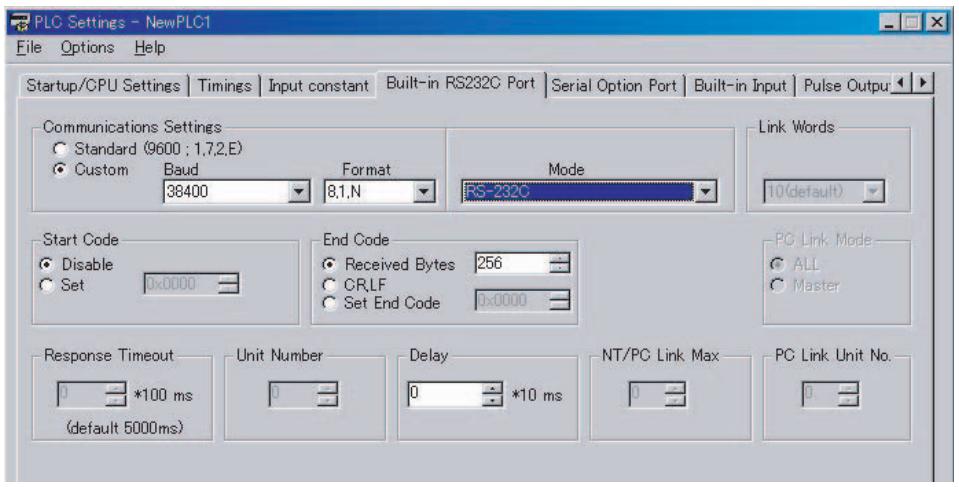
Function
- RXD(235) reads data that has been received in no-protocol mode at the CPU Unit's built-in RS-232C port or the Serial Option Board port (the port is specified with bits 8 to 11 of C) and stores N bytes of data in words D to D + (N ÷ 2) - 1 . If N bytes of data has not been received at the port, then only the data that has been received will be stored.
- The following receive message frame format can be set in the PLC Setup.
1) Start code: None or 00 to FF hex
2) End code: None, CR+LF, or 00 to FF hex. If no end code is specified, the number of bytes to received is set from 00 to FF hex (1 to 256 decimal; 00 specifies 256 bytes).
Data will be stored in memory in the order specified in C0 to C3.
- Cases where the reception completion flag turns ON
The Reception Completed Flag (note (a)) will turn ON when the number of bytes specified in the PLC Setup has been received. When the Reception Completed Flag turns ON, the number of bytes in the Reception Counter (note (b)) will have the same value as the number of receive bytes specified in the PLC Setup.
If an end code is specified in the PLC Setup, the Reception Completed Flag (note (a)) will turn ON when the end code is received or when 256 bytes of data have been received. If more bytes are received than specified, the Reception Overflow Flag (note (c)) will turn ON.
- When RXD(235) is executed, data is stored in memory starting at D, the Reception Completed Flag (note (a)) will turn OFF (even if the Reception Overflow Flag (note (c)) is ON), and the Reception Counter (note (b)) will be cleared to 0.
- If the RS-232C Port Restart Bit (note (d)) is turned ON, the Reception Completed Flag (note (a)) will be turned OFF (even if the Reception Overflow Flag is ON), and the Reception Counter (note (b)) will be cleared to 0.
- Specification of monitor in bits C4 to C7 for the CS and DR signals takes effect as follows:
1) If CS signal monitoring is specified in C, the status of the CS signal will be stored in bit 15 of D.
2) If DR signal monitoring is specified in C, the status of the DR signal will be stored in bit 15 of D.
3) If CS and DR signal monitoring is specified in C, the status of the CS signal will be stored in bit 15 of D and the status of the DR signal will be stored in bit 14 of D.
- If 1, 2, or 3 hex is specified for CS and DR signal control in C, RXD(235) will be executed regardless of the status of the Receive Completed Flag (note (a)).
- Receive data will not be stored if CS or DR signal monitoring is specified.
- Up to 259 bytes can be received, including the receive data (N = 256 bytes max.), the start code, and the end code.
- Specify the size of the receive data, not including the start code and end code, in N.
Note Related Auxiliary Area and CIO Area Addresses
(a) Reception Completed Flags
Built-in RS232C port A392.06
Serial Option Board port: A392.14
(b) Reception Counters
Built-in RS232C port A393
Serial Option Board port: A394
(c) Reception Overflow Flags
Built-in RS232C port A392.07
Serial Option Board port: A392.15
Built-in RS232C port A526.00
Serial Option Board port: A526.01
- Start Code/End Code Settings and Receive Data
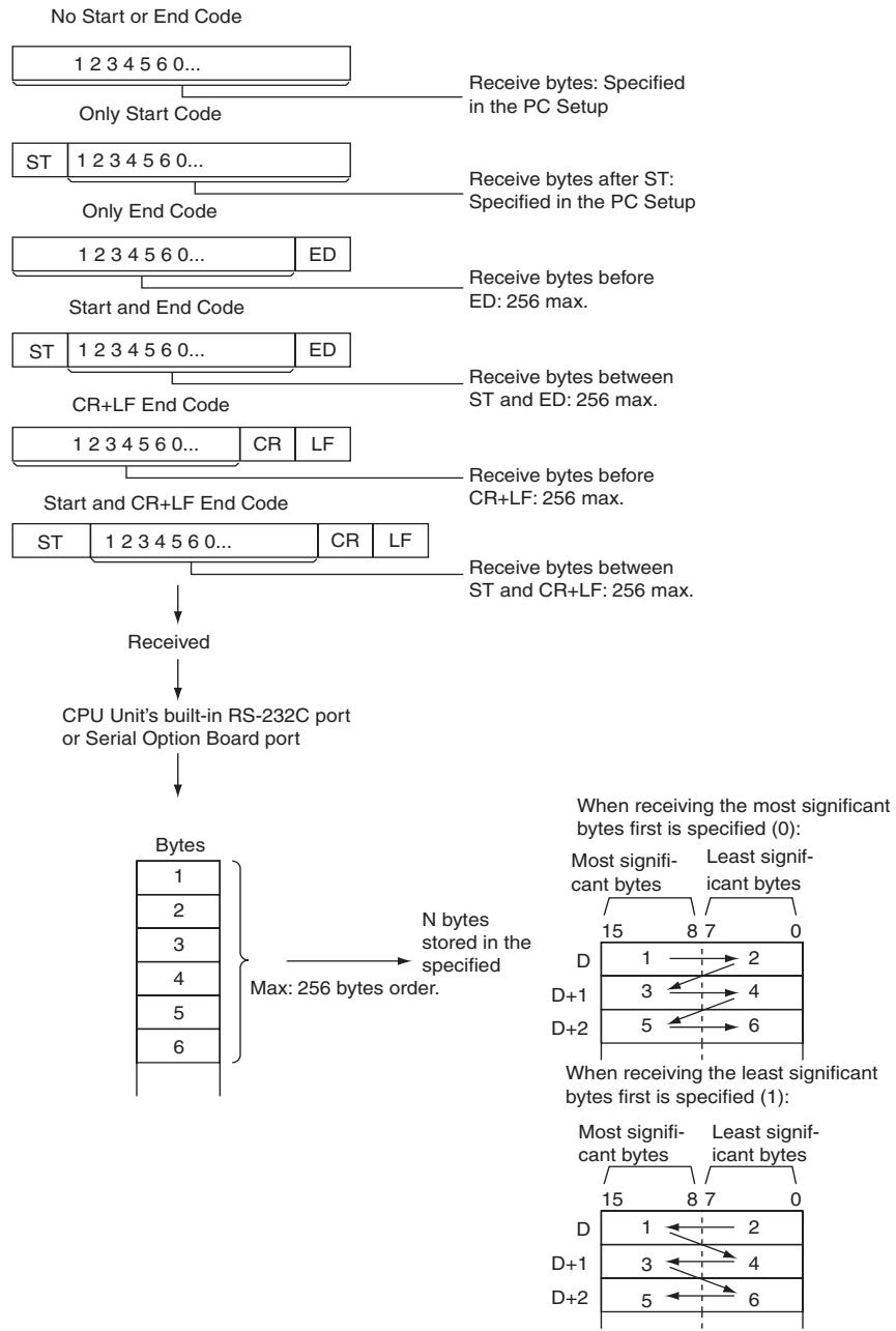
Hint
- When RXD(235) is used to read data that was received at one of the Serial Option Board's ports, the port's reception buffer is cleared after RXD(235) is executed. Consequently, RXD(235) can not be executed repeatedly to read a block of data in parts.
Precautions
- RXD(235) can be used only for the CPU Unit's RS-232C port or the Serial Option Board port. In addition, the port must be set to no-protocol mode.
- Execute this instruction when the reception completion flag (RS-232C incorporated in the CPU unit: A392.06, Serial Option Board: A392.14) is 1 (ON) to receive data (from the reception buffer).
- When data is received, the data must be read by an RXD instruction or the next data cannot be received. When the reception completion flag turns ON, read the received data with an RXD instruction before the next reception.
- Specify the size of the receive data, not including the start code and end code, in N.
- If 0 is specified for N, the Reception Completed Flag and Reception Overflow Flag (note(a)) will be turned OFF, the Reception Counter (note(b)) will be cleared to 0, and nothing will be stored in memory.
Sample program
- Receiving data
This example shows how to receive data from the V530-R150V3 2D Code Reader as an example of communicating with an external device.
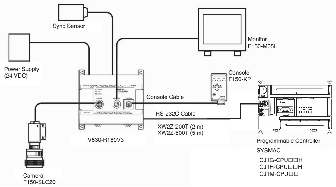
Hardware Configuration
In this example, the external device is connected to the RS-232C port built into the CPU Unit.
First, set the reading conditions for the Code Reader.
Communications Settings
The communications settings of the Code Reader are given in the following table. These are the default settings.
| Item | Setting |
| Communications mode | No-protocol |
| Baud rate | 38,400 bps |
| Data bit length | 8 bits |
| Parity | None |
| Stop bits | 1 |
| Start code | None |
| End code | #000D (CR) |
Set the PLC communications settings to the same values in the PLC Setup. Only the end code needs to be set.
Programming Example
If CIO 0.02 turns ON while the RS-232C Port Send Ready Flag (A392.05) is ON, the number of bytes of reading results specified in the RS-232C Port Reception Counter (A393) are read from the Code Reader connected to the CPU Unit's built-in RS-232C port and stored starting from the upper byte of D100.
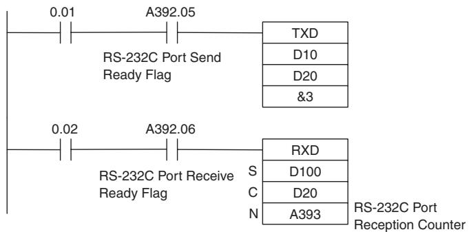
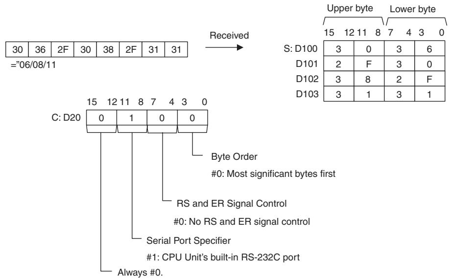
Controlling Signals
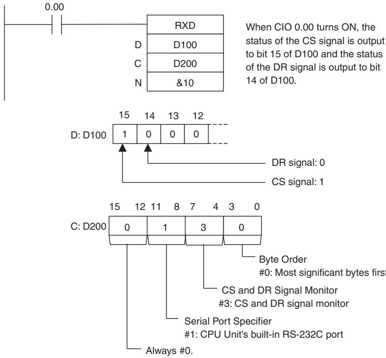
Clock Instructions
CADD/CSUB
| Instruction | Mnemonic | Variations | Function code | Function |
| CALENDAR ADD | CADD | @CADD | 730 | Adds time to the calendar data in the specified words. |
| CALENDAR SUBTRACT | CSUB | @CSUB | 731 | Subtracts time from the calendar data in the spec-ified words. |
| Symbol | CADD | CSUB | ||
| CADD(730) | C: First calendar wordT: First time wordR: First result word | CSUB(731) | C: First calendar wordT: First time wordR: First result word | |
| C | C | |||
| T | T | |||
| R | R | |||
Applicable Program Areas
| Area | Step program areas | Subroutines | Interrupt tasks |
| Usage | OK | OK | OK |
Operands
| Operand | Description | Data type | Size |
| C | First calendar word | WORD | 3 |
| T | First time word | DWORD | 2 |
| R | First result word | WORD | 3 |
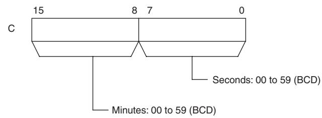
- CADD
C through C+2: Calendar Data
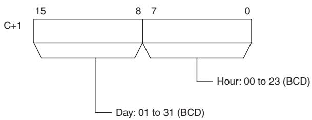
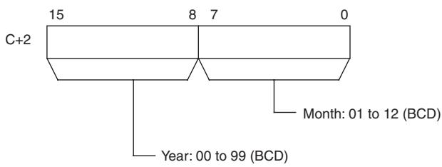
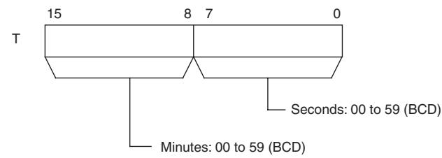
T and T+1: Time Data
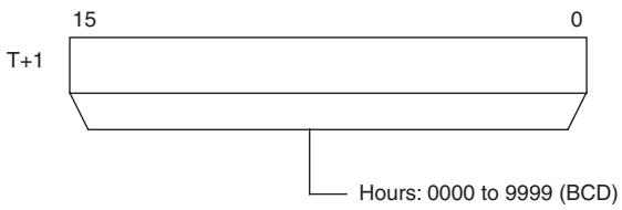
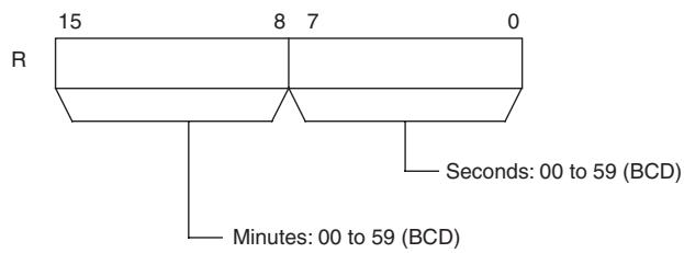
R through R+2: Result Data
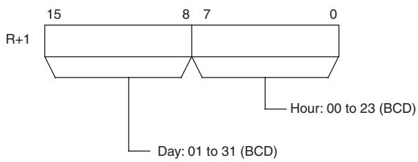
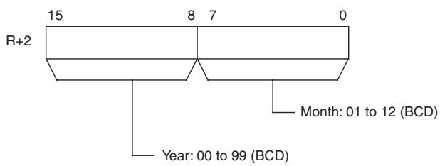
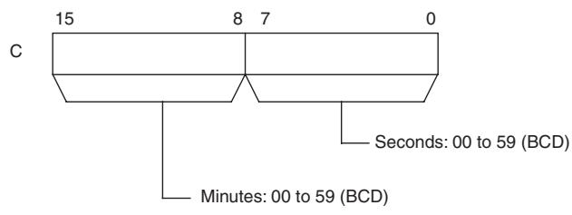
CSUB
C through C+2: Calendar Data

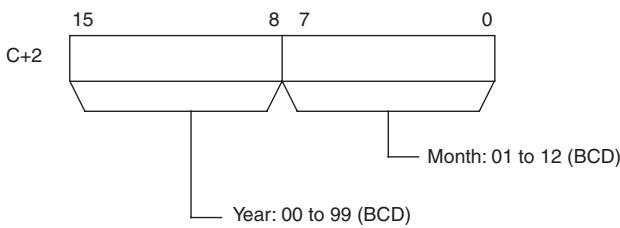
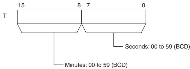
T and T+1: Time Data
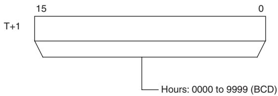
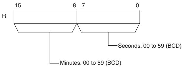
R through R+2: Result Data
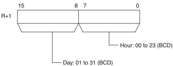
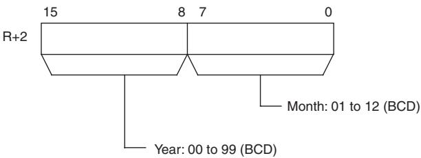
- Operand Specifications
| Area | Word addresses | Indirect DM addresses | Constants | CF | Pulse bits | TR bits | |||||||
| CIO | WR | HR | AR | T | C | DM | @DM | *DM | |||||
| C | OK | OK | OK | OK | OK | OK | OK | OK | OK | --- | --- | --- | --- |
| T | OK | ||||||||||||
| R | --- | ||||||||||||
Flags
| Name | Label | Operation |
| Error Flag | P_ER | ON if the calendar data in C through C+2 is not within the specified ranges. ON if the time data in T and T+1 is not within the specified ranges. OFF in all other cases. |
| Equal Flag | P_EQ | ON when the result of a CSUB instruction is 0. OFF in all other cases. |
Function
CADD
CADD(730) adds the calendar data (words C through C+2) to the time data (words T and T+1) and outputs the resulting calendar data to R through R+2.
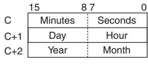
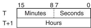
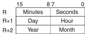
CSUB
CSUB(731) subtracts the time data (words T and T+1) from the calendar data (words C through C+2) to and outputs the resulting calendar data to R through R+2.
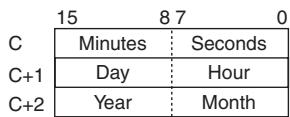
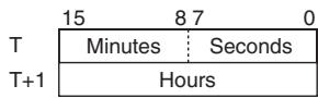
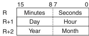
Sample program CADD
When CIO 0.00 turns ON in the following example, the calendar data in D100 through D102 (year, month, day, hour, minutes, seconds) is added to the time data in D200 and D201 (hours, minutes, seconds) and the result is output to D300 through D302.
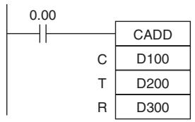
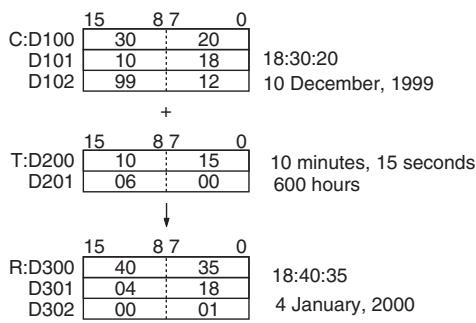
CSUB
When CIO 0.00 turns ON in the following example, the time data in D200 and D201 (hours, minutes, seconds) is subtracted from the calendar data in D100 through D102 (year, month, day, hour, minutes, seconds) and the result is output to D300 through D302.
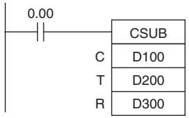
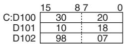
18:30:20
10 July, 1998

50 hours, 10 minutes, 15 seconds
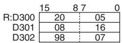
16:20:05
8 July, 1998
DATE
| Instruction | Mnemonic | Variations | Function code | Function |
| CLOCK ADJUSTMENT | DATE | @DATE | 735 | Changes the internal clock setting to the setting in the specified source words. |
| Symbol | DATE | |
| — | — DATE(735) — S | S: First source word | |
Applicable Program Areas
| Area | Step program areas | Subroutines | Interrupt tasks |
| Usage | OK | OK | OK |
Operands
| Operand | Description | Data type | Size |
| S | First source word | LWORD | 4 |
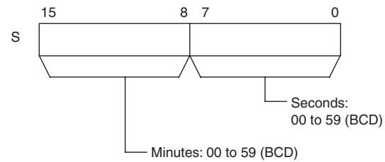
S through S+3: New Clock Setting
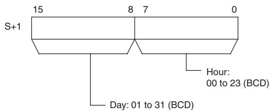
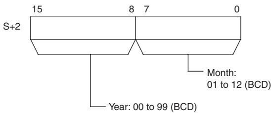
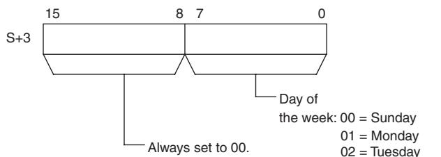
Note S through S + 3 must be in the same data area.
- Operand Specifications
| Area | Word addresses | Indirect DM addresses | Constants | CF | Pulse bits | TR bits | |||||||
| CIO | WR | HR | AR | T | C | DM | @DM | *DM | |||||
| S | OK | OK | OK | OK | OK | OK | OK | OK | OK | --- | --- | --- | --- |
Flags
| Name | Label | Operation |
| Error Flag | P_ER | ON if the new clock setting in S through S+3 is not within the specified rangeOFF in all other cases.ON when DATE instruction is executed for CP1E-E□□□□-□. |
Related Auxiliary Area Words and Bits
| Name | Address | Operation |
| Clock data | A351 to A354 | A351.00 to A351.07: Seconds (00 to 59) (BCD) A351.08 to A351.15: Minutes (00 to 59) (BCD) A352.00 to A352.07: Hours (00 to 23) (BCD) A352.08 to A352.15: Day of the month (01 to 31) (BCD) A353.00 to A353.07: Month (01 to 12) (BCD) A353.08 to A353.15: Year (00 to 99) (BCD) A354.00 to A354.07: Day of the week (00 to 06) (BCD) 00: Sunday, 01: Monday, 02: Tuesday, 03: Wednesday, 04: Thursday, 05: Friday, 06: Saturday |
Function
DATE(735) changes the internal clock setting according to the clock data in the four source words. The new internal clock setting is immediately reflected in the Calendar/Clock Area (A351 to A354).
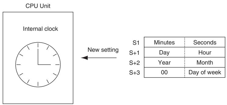
Hint
The internal clock setting can also be changed from a Peripheral Device or the CLOCK WRITE FINS command (0702).
Precaution
- An error will not be generated even if the internal clock is set to a non-existent date (such as November 31).
- In case this instruction is executed for E-type CPU Unit (CP1E-E□□□□-□), the error flag will turn ON and the instruction cannot be executed. For E-type CPU Unit, A351 to A354 is always 01-01-01 01:01:01 Sunday.
Sample program
When CIO 0.00 turns ON in the following example, the internal clock is set to 20:15:30 on Thursday, October 9, 1998.

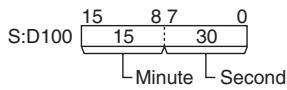
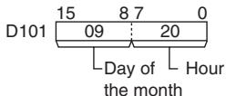
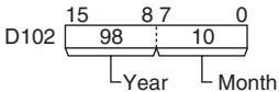
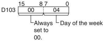
Failure Diagnosis Instructions
FAL
| Instruction | Mnemonic | Variations | Function code | Function |
| FAILURE ALARM | FAL | @FAL | 006 | Generates or clears user-defined non-fatal errors. Non-fatal errors do not stop PLC operation. |
| Symbol | FAL | |||
| Generating or Clearing User-defined Non-fatal Errors | Generating Non-fatal System Errors | |||
| FAL(006) | N: FAL number | FAL(006) | N: FAL number (value in A529) | |
| N | S: First message word or constant (0000 to FFFF) | N | S: First word containing the error code and error details | |
Applicable Program Areas
| Area | Step program areas | Subroutines | Interrupt tasks |
| Usage | OK | OK | OK |
Operands
| Operand | Description | Data type | Size |
| N | FAL number | Constants only | 1 |
| S | First message word or constant / First word containing the error code and error details | WORD | Variable |
- Generating or Clearing User-defined Non-fatal Errors
Note The value of operand N must be different from the content of A529 (the system-generated FAL/FALS number).
| Generates a non-fatal error | Clears all non-fatal errors | |
| N | 1 to 511 (These FAL numbers are shared with FALS numbers.) | 0 |
| S | Word address:Generates a non-fatal error with the corresponding FAL number.The 16-character ASCII message contained in S through S+7 will be displayed on the Programming Device.#0000 to #FFFF:Generates a non-fatal error with the corresponding FAL number (no message). | #FFFF: clears all non-fatal errors.#0001 to #01FF: clears the non-fatal error with the corresponding FAL number.Other: clears the most serious non-fatal error. |
- Generating Non-fatal System Errors
Note The value of operand N must be the same as the content of A529 (the system-generated FAL/FALS number).
| Generates a non-fatal error | |
| N | 1 to 511 (These FAL numbers are shared with FALS numbers.) |
| S | Error code that will be generated. (See Function below.) |
| S+1 | Error details code that will be generated. (See Function below.) |
- Operand Specifications
| Area | Word addresses | Indirect DM addresses | Constants | CF | Pulse bits | TR bits | |||||||
| CIO | WR | HR | AR | T | C | DM | @DM | *DM | |||||
| N | --- | --- | --- | --- | --- | --- | --- | --- | --- | OK | --- | --- | --- |
| S | OK | OK | OK | OK | OK | OK | OK | OK | OK | ||||
Flags
| Name | Label | Operation |
| Error Flag | ER | ON if N is not within the specified range of 0 to 511 decimal.ON if a non-fatal system error is being generated, but the specified error code or error details code is incorrectOFF in all other cases. |
Related Auxiliary Area Words and Bits
- Auxiliary Area Words/Flags for User-defined Errors Only
| Name | Address | Operation |
| FAL Error Flag | A402.15 | ON when an error is generated with FAL(006). |
| Executed FAL Number Flags | A360.01 to A391.15 | When an error is generated with FAL(006), the corresponding flag will be turned ON. Flags A360.01 to A391.15 correspond to FAL numbers1 to 511 decimal. |
- Auxiliary Area Words/Flags for System Errors Only
| Name | Address | Operation |
| System-generated FAL/FALS number | A529 | A dummy FAL/FALS number is used when a system error is generated with FAL(006). Set the same dummy FAL/FALS number in this word (0001 to 01FF hex, 1 to 511 decimal). |
- Auxiliary Area Words/Flags for both User-defined and System Errors
| Name | Address | Operation |
| Error Log Area | A100 to A199 | The Error Log Area contains the error codes and time/date of occurrence for the most recent 20 errors, including errors generated by FAL(006). |
| Error code | A400 | When an error occurs its error code is stored in A400. The error codes for FAL numbers 0001 to 01FF are 4101 to 42FF, respectively. If two or more errors occur simultaneously, the error code of the most serious error will be stored in A400. |
Clearing Non-fatal Errors without a Programming Device
- Clearing User-defined Non-fatal Errors
When FAL(006) is executed with N set to 0, non-fatal errors can be cleared. The value of S will determine the processing, as shown in the following table.
| S | Process |
| &1 to &511 (0001 to 01FF hex) | The FAL error of the specified number will be cleared. |
| FFFF hex | All non-fatal errors (including system errors) will be cleared. |
| 0200 to FFFE hex or word specification | The most serious non-fatal error (even if it is a non-fatal system error) that has occurred. When more than one FAL error has occurred, the FAL error with the smallest FAL number will be cleared. |
- Clearing Non-fatal System Errors
There are two ways to clear non-fatal system errors generated with FAL(006).
- Turn the PLC OFF and then ON again.
- When keeping the PLC ON, the system error must be cleared as if the specified error had actually occurred.
Function
- Generating Non-fatal User-defined Errors
The following table shows the error codes and FAL Error Flags for FAL(006).
| FAL number | 1 to 511 decimal |
| FAL error codes | 4101 to 42FF |
| Executed FAL Number Flags | A360.01 to A391.15 |
When FAL(006) is executed with N set to an FAL number (&1 to &511) that is not equal to the content of A529 (the system-generated FAL/FALS number), a non-fatal error will be generated with that FAL number and the following processing will be performed:
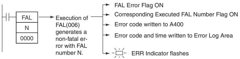
- The FAL Error Flag (A402.15) will be turned ON. (PLC operation will continue.)
- The Executed FAL Number Flag will be turned ON for the corresponding FAL number. Flags A360.01 to A391.15 correspond to FAL numbers 0001 to 01FF (1 to 511).
- The error code will be written to A400. Error codes 4101 to 42FF correspond to FAL numbers 0001 to 01FF (1 to 511).
- The error code and the time that the error occurred will be written to the Error Log Area (A100 through A199).
Note The error record will not be written to the Error Log Area if the Don't register FAL to error log Option in the PLC Setup is selected.
- The ERR Indicator on the CPU Unit will flash.
- If a word address has been specified in S, the message beginning at S will be registered (displayed on the Programming Device).
Note If a fatal error or a more serious non-fatal error occurs at the same time as the FAL(006) instruction, the more serious error's error code will be written to A400.
- Generating Non-fatal System Errors
When FAL(006) is executed with N set to an FAL number (&1 to &511) that is equal to the content of A529 (the system-generated FAL/FALS number), a non-fatal error will be generated with the error code and error details code specified in S and S+1. The following processing will be performed at the same time:

- The specified error code will be written to A400.
- The error code and the time that the error occurred will be written to the Error Log Area (A100 through A199).
- The appropriate Auxiliary Area Flags are set based on the error code and error details.
- The ERR Indicator on the CPU Unit will flash and PLC operation will continue.
Note 1 FAL(006) can be used to generate non-fatal errors from the system when debugging the program. For example, a system error can be generated intentionally to check whether or not error messages are being displayed properly at an interface such as a Programmable Terminal (PT).
2 The value of A529 (the system-generated FAL/FALS number) is a dummy FAL number (FAL and FALS numbers are shared.) used when a non-fatal error is generated intentionally by the system. This number is a dummy FAL number, so it does not change the status of the Executed FAL Number Flags (A360.01 to A391.15) or the error code.
When it is necessary to generate two or more system errors (fatal and/or non-fatal errors), different errors can be generated by executing the FAL/FALS instructions more than once with the same values in A529 and N, but different values in S and S+1.
3 If a more serious error (including a system-generated fatal error or FALS(007) error) occurs at the same time as the FAL(006) instruction, the more serious error's error code will be written to A400.
4 To clear a system error generated by FAL(006), turn the PLC OFF and then ON again. The PLC can be kept ON, but the same processing will be required to clear the error as if the specified error had actually occurred.
Refer to CP1E CPU Unit Hardware Operation Manual or CP1E CPU Unit Software Operation Manual.
The following table shows how to specify error codes and error details in S and S + 1 .
| Error name | S | S+1 |
| PLC Setup Error | 009B hex | PLC Setup Error Location 0000 to FFFF hex |
| Built-in Analog Error | 008A hex | --- (not fixed) |
| Option Board Error | 00D1 hex | Option Board Slot No. 0001 hex |
| Battery Error | 00F7 hex | --- (not fixed) |
- Disabling Error Log Entries of User-defined Errors
Normally when FAL(006) generates a user-defined error, the error code and the time that the error occurred are written to the Error Log Area (A100 through A199). It is possible to set the PLC Setup so that user-defined errors generated by FAL(006) are not recorded in the Error Log.
Note Even though the error will not be recorded in the Error Log, the FAL Error Flag (402.15) will be turned ON, the corresponding flag in the Executed FAL Number Flags (A360.01 to A391.15) will be turned ON, and the error code will be written to A400.
Disable Error Log entries for user-defined FAL(006) errors when you want to record only the system-generated errors. For example, this function is useful during debugging if the FAL(006) instructions are used in several applications and the Error Log is becoming full of user-defined FAL(006) errors.
- The following screen capture shows the PLC Setup setting from the CX-Programmer.
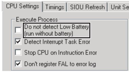
Note Even if PLC Setup word 129 bit 15 is set to 1 (Do not record FAL Errors in Error Log.), the following errors will be recorded:
- Fatal errors generated by FALS(007)
- Non-fatal errors from the system
- Fatal errors from the system
- Non-fatal errors from the system generated intentionally with FAL(006)
- Fatal errors from the system generated intentionally with FALS(007)
- Displaying Messages with Non-fatal User-defined Errors
- If S is a word address and an ASCII message has been stored at S, that message will be displayed at the Peripheral Device when FAL(006) is executed. (If a message is not required, set S to a constant.)
- The message beginning at S will be registered when FAL(006) is executed. Once the message is registered, it will be displayed.
- An ASCII message up to 16 characters long can be stored in S through S+7. The leftmost (most significant) byte in each word is displayed first.
- The end code for the message is the null character (00 hexadecimal).
- All 16 characters in words S to S+7 will be displayed if the null character is omitted.
- If the contents of the words containing the message are changed after FAL(006) is executed, the message will change accordingly.
Sample program
- Generating a Non-fatal Error
When CIO 0.00 is ON in the following example, FAL(006) will generate a non-fatal error with FAL number 31 and execute the following processes.
- The FAL Error Flag (A402.15) will be turned ON.
- The corresponding Executed FAL Number Flag (A361.15) will be turned ON.
- The corresponding error code (411F) will be written to A400.
- The error code and the time/date that the error occurred will be written to the Error Log Area (A100 through A199).
- The ERR Indicator on the CPU Unit will flash.
- The ASCII message in D100 to D107 will be displayed at the Peripheral Device.
Note If a message is not required, specify a constant for S.
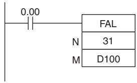

Note If two or more errors occur at the same time, the error code of the most serious error (with the highest error code) will be stored in A400.
- Clearing a Particular Non-fatal Error
When CIO 0.01 is ON in the following example, FAL(006) will clear the non-fatal error with FAL number 31, turn OFF the corresponding Executed FAL Number Flag (A361.15), and turn OFF the FAL Error Flag (A402.15).
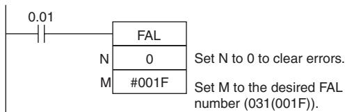
- Clearing All Non-fatal Errors
When CIO 0.02 is ON in the following example, FAL(006) will clear all of the non-fatal errors, turn OFF the Executed FAL Number Flags (A360.01 to A391.15), and turn OFF the FAL Error Flag (A402.15).
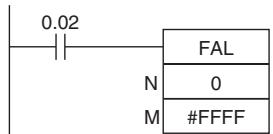
Set N to 0 to clear errors.
Set M to FFFF to clear all non-fatal errors (both FAL(006) and system errors).
- Clearing the Most Serious Non-fatal Error
When CIO 0.03 is ON in the following example, FAL(006) will clear the most serious non-fatal error that has occurred and reset the error code in A400. If the cleared error was originally generated by FAL(006), the corresponding Executed FAL Number Flag and the FAL Error Flag (A402.15) will be turned OFF.
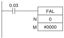
Set N to 0 to clear errors.
Set M to 0000, another constant between 0200 and FFFE, or a word address to clear the most serious non-fatal error. (In this case, M is set to 0000.)
- Generating a Non-fatal System Error
When CIO 0.00 is ON in the following example, FAL(006) will generate Option Board Error. In this case, dummy FAL number 10 is used and the corresponding value (000A hex) is stored in A529.
- The specified error code (00D1) will be written to A400 if it is the most serious error.
- The error code and the time/date that the error occurred will be written to the Error Log Area (A100 through A199).
- Option Board Error Flag(A315.13) will be turned ON.
- The CPU Unit's ERR Indicator will flash.
- Option Board Error will occur.
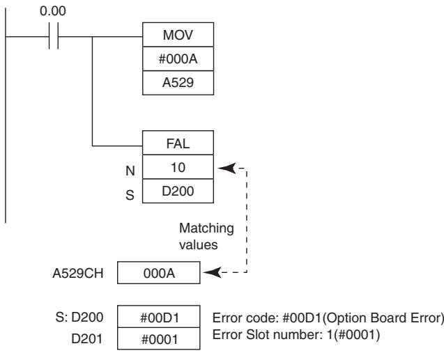
FALS
| Instruction | Mnemonic | Variations | Function code | Function |
| SEVERE FAILURE ALARM | FALS | --- | 007 | Generates user-defined fatal errors. Fatal errors stop PLC operation. |
| Symbol | FALS | |||
| Generating User-defined Fatal Errors | Generating Fatal System Errors | |||
| FALS(007) | N: FAL number | FALS(007) | N: FAL number (value in A529) | |
| N | S: First message word or constant (0000 to FFFF) | N | S: First word containing the error code and error details | |
Applicable Program Areas
| Area | Step program areas | Subroutines | Interrupt tasks |
| Usage | OK | OK | OK |
Operands
| Operand | Description | Data type | Size |
| N | FAL number | Constants only | 1 |
| S | First message word or constant / First word containing the error code and error details | WORD | Variable |
- Generating User-defined Fatal Errors
Note The value of operand N must be different from the content of A529 (the system-generated FAL/FALS number).
| Generates a non-fatal error | |
| N | 1 to 511 (These FALS numbers are shared with FALS numbers.) |
| S | Specifies the first of eight words containing an ASCII message to be displayed on the Programming Device. Specify a constant (0000 to FFFF) if a message is not required. |
- Generating Fatal Errors from the System
The following table shows the function of the operands.
Note The value of operand N must be the same as the content of A529 (the system-generated FAL/FALS number).
| Generates a non-fatal error | |
| N | 1 to 511 (These FALS numbers are shared with FAL numbers.) |
| S | Error code that will be generated. (See Description below.) |
| S+1 | Error details code that will be generated. (See Description below.) |
-Operand Specifications
| Area | Word addresses | Indirect DM addresses | Constants | CF | Pulse bits | TR bits | |||||||
| CIO | WR | HR | AR | T | C | DM | @DM | *DM | |||||
| N | --- | --- | --- | --- | --- | --- | --- | --- | --- | OK | --- | --- | --- |
| S | OK | OK | OK | OK | OK | OK | OK | OK | OK | ||||
Flags
| Name | Label | Operation |
| Error Flag | P_ER | ON if N is not within the specified range of 0001 to 01FF (1 to 511 decimal).ON if a fatal system error is being generated, but the specified error code or error details code is incorrectOFF in all other cases. |
Related Auxiliary Area Words and Bits
- Auxiliary Area Words/Flags for User-defined Errors Only
| Name | Address | Operation |
| FALS Error Flag | A401.06 | ON when an error is generated with FALS(007). |
- Auxiliary Area Words/Flags for System Errors Only
| Name | Address | Operation |
| System-generated FAL/FALS number | A529 | A dummy FAL/FALS number is used when a system error is generated with FALS(007). Set the same dummy FAL/FALS number in this word (0001 to 01FF hex, 1 to 511 decimal). |
- Auxiliary Area Words/Flags for both User-defined and System Errors
| Name | Address | Operation |
| Error Log Area | A100 to A199 | The Error Log Area contains the error codes and time/date of occurrence for the most recent 20 errors, including errors generated by FALS(007). |
| Error code | A400 | When an error occurs its error code is stored in A400. The error codes for FALS numbers 0001 to 01FF (1 to 511 decimal) are C101 to C2FF, respectively.Note If two or more errors occur simultaneously, the error code of the most serious error will be stored in A400. |
Function
- Generating Fatal User-defined Errors
| FALS number | 1 to 511 |
| FALS error codes | C101 TO C2FF |
When FALS(007) is executed with N set to an FALS number (1 to 511) that is not equal to the content of A529 (the system-generated FAL/FALS number), a fatal error will be generated with that FALS number and the following processing will be performed:
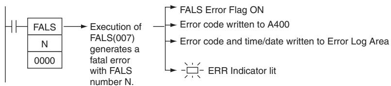
- The FALS Error Flag (A401.06) will be turned ON. (PLC operation will stop.)
- The error code will be written to A400. Error codes C101 to C2FF correspond to FALS numbers 0001 to 01FF (1 to 511).
Note If an error more serious than the FALS(007) instruction (one with a higher error code) has occurred, A400 will contain the more serious error's error code.
- The error code and the time/date that the error occurred will be written to the Error Log Area (A100 through A199).
- The ERR Indicator on the CPU Unit will be lit.
- If a word address has been specified in S, the ASCII message beginning at S will be registered (displayed on the Peripheral Device).
Note 1 If an error that is more serious (including fatal system errors) than an error registered with this instruction occurs simultaneously, the error code of that error will be set in error code A400.
2 The end code for the message is the null character (00 hexadecimal). All 16 characters in words S to S+7 will be displayed if the null character is omitted.
3 N must between 0001 and 01FF. An error will occur and the Error Flag will be turned ON if N is outside of the specified range.
4 When a user-defined fatal error is registered, the I/O memory and output status from output units will be as indicated below.
| I/O memory | Output status from output units | ||
| IOM Hold Bit (A500.12). | ON | Hold | OFF |
| OFF | Hold | OFF | |
- Generating Non-fatal System Errors
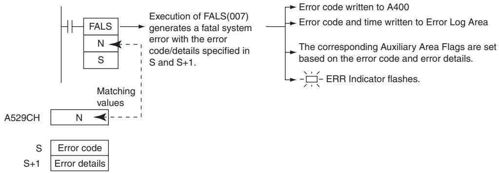
When FALS(007) is executed with N set to an FAL number (1 to 511) that is equal to the content of A529 (the system-generated FAL/FALS number), a fatal error will be generated with the error code and error details code specified in S and S+1. The following processing will be performed at the same time:
- The specified error code will be written to A400.
- The error code and the time that the error occurred will be written to the Error Log Area (A100 through A199).
- The appropriate Auxiliary Area Flags are set based on the error code and error details.
- The ERR Indicator on the CPU Unit will light and PLC operation will be stopped.
Note 1 The value of A529 (the system-generated FAL/FALS number) is a dummy FAL number (FAL and FALS numbers are shared.) used when a non-fatal error is generated intentionally by the system. This number is a dummy FAL number, so it is not reflected in the error code.
When it is necessary to generate two or more system errors, different errors can be generated by executing the FAL/FALS instructions more than once with the same values in A529 and N, but different values in S and S+1.
2 If a more serious error (including a system-generated fatal error or another FALS(007) error) occurs at the same time as the FALS(007) instruction, the more serious error's error code will be written to A400.
3 To clear a system error generated by FALS(007), turn the PLC OFF and then ON again. The PLC can be kept ON, but the same processing will be required to clear the error as if the specified error had actually occurred. Refer to CP1E CPU Unit Hardware Operation Manual or CP1E CPU Unit Software Operation Manual for details.
4 The following table shows how the IOM Hold Bit affects the status of I/O memory and the status of outputs on Output Units after a fatal system error has been generated with FALS(007).
| Status of I/O memory | Status of outputs on Output Units | ||
| IOM Hold Bit (A500.12) | ON | Retained | OFF |
| OFF | Cleared | OFF | |
The following table shows how to specify error codes and error details in S and S + 1
| Error name | S | S+1 |
| Error code | Error details | |
| Memory Error | 80F1 hex | Bits 00 to 09: Memory Error Location Bit 00: User program Bit 01: I/O memory Bit 04: PLC Setup Bits 2, 3, 5 to 15: Invalid |
| I/O Bus Error | 80CA hex | CP1W Expansion I/O Unit, Expansion Unit #0A0A hex |
| Too Many I/O Points Error | 80E1 hex | Bits 13 to 15: Error Cause Bits 00 to 12: Details • The channel number of CP1W Expansion I/O Unit is too many. Bits 13 to 15: 001 Bits 00 to 12: All zeroes |
| Program Error | 80F0 hex | Bits 08 to 15: Error Cause Bit 15: UM overflow error Bit 14: Illegal instruction error Bit 13: Differentiation overflow error Bit 12: Task error Bit 11: No END error Bit 10: Illegal access error Bit 09: Indirect DM BCD error Bit 08: Instruction error Bits 00 to 07: Invalid |
| Cycle Time Overrun Error | 809F hex | #0000 hex |
- Displaying Messages with Fatal User-defined Errors
- If S is a word address, the ASCII message beginning at S will be displayed at the Programming Device when FALS(007) is executed. (If a message is not required, set S to a constant.)
- The message beginning at S will be registered when FALS(007) is executed. Once the message is registered, it will be displayed.
- An ASCII message up to 16 characters long can be stored in S through S+7. The leftmost (most significant) byte in each word is displayed first.
- The end code for the message is the null character (00 hexadecimal).
- All 16 characters in words S to S+7 will be displayed if the null character is omitted.
- If the contents of the words containing the message are changed after FALS(007) is executed, the message will change accordingly.
- Clearing FALS(007) Fatal System Errors
There are two ways to clear fatal system errors generated with FALS(007).
- Turn the PLC OFF and then ON again.
- When keeping the PLC ON, the system error must be cleared as if the specified error had actually occurred.
- Clearing FALS(007) User-defined Fatal Errors
To clear errors generated by FALS(007), first eliminate the cause of the error and then either clear the error from a Programming Device or turn the PLC OFF and then ON again.
Precaution
When a fatal system error is registered, if the IOM Hold Bit is OFF, I/O memory will be cleared.
Sample program
- Generating a User-defined Error
When CIO 0.00 is ON in the following example, FALS(007) will generate a fatal error with FAL number 31 and execute the following processes.
- The FALS Error Flag (A401.06) will be turned ON.
- The corresponding error code (C11F) will be written to A400.
- The error code and the time/date that the error occurred will be written to the Error Log Area (A100 through A199).
- The ERR Indicator on the CPU Unit will be lit.
- The ASCII message in D100 to D107 will be displayed at the Peripheral Device.
Note If a message is not required, specify a constant for S.
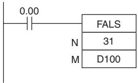
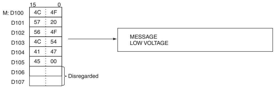
Note A400 will contain the error code of the most serious of all of the errors that have occurred, including non-fatal and fatal system errors, as well as errors generated by FAL(006) and FAL(007).
- Generating a Non-fatal System Error
When CIO 0.00 is ON in the following example, FALS(007) will generate Memory Error (User program Error). In this case, dummy FAL number 10 is used and the corresponding value (80F1 hex) is stored in A529.
- The specified error code (80F1) will be written to A400 if it is the most serious error.
- The error code and the time/date that the error occurred will be written to the Error Log Area (A100 through A199).
- The Memory Error Flag (A401.15) will be turned ON.
- The CPU Unit's ERR Indicator will light and PLC operation will stop.
- Memory Error has occurred.
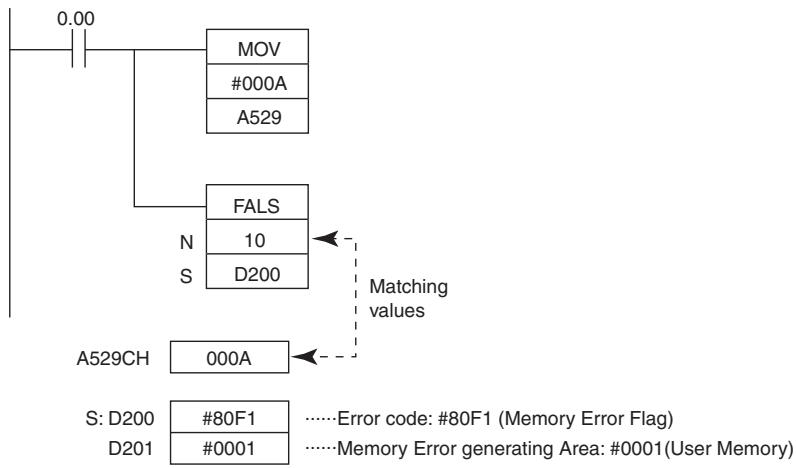
Other Instructions
STC/CLC
| Instruction | Mnemonic | Variations | Function code | Function |
| SET CARRY | STC | @STC | 040 | Sets the Carry Flag (CY). |
| CLEAR CARRY | CLC | @CLC | 041 | Turns OFF the Carry Flag (CY). |
| Symbol | STC | CLC |
| STC(040) | CLC(041) |
Applicable Program Areas
| Area | Step program areas | Subroutines | Interrupt tasks |
| Usage | OK | OK | OK |
Flags
| Operand | Description | Data type | |
| STC | CLC | ||
| Carry Flag | P_CY | ON | OFF |
Function
STC
When the execution condition is ON, STC(040) turns ON the Carry Flag (CY). Although STC(040) turns the Carry Flag ON, the flag will be turned ON/OFF by the execution of subsequent instructions which affect the Carry Flag.
ROL(027) and ROR(028) make use of the Carry Flag in their rotation shift operations.
- CLC
When the execution condition is ON, CLC(040) turns OFF the Carry Flag (CY). Although CLC(040) turns the Carry Flag OFF, the flag will be turned ON/OFF by the execution of subsequent instructions which affect the Carry Flag.
+C(402), +CL(403), +BC(406), +BCL(407), -C(412), -CL(413), -BC(416), and -BCL(417) make use of the Carry Flag in their addition operations. Use CLC(041) just before any of these instructions to prevent any influence from other preceding instructions.
ROL(027) and ROR(028) make use of the Carry Flag in their rotation shift operations.
Hint
The +(400), +L(401), +B(404), +BL(405), -(410), -L(411), -B(414) , and -BL(415) instructions do no include the Carry Flag in their addition and subtraction operations. In general, use these instructions when performing addition or subtraction.
WDT
| Instruction | Mnemonic | Variations | Function code | Function |
| EXTEND MAXIMUM CYCLE TIME | WDT | @WDT | 094 | Extends the maximum cycle time, but only for the cycle in which the instruction is executed. WDT(094) can be used to prevent errors for long cycle times when a longer cycle time is temporarily required for special processing. |
| Symbol | WDT |
| — |— WDT(094) — T |— T: Timer setting |
Applicable Program Areas
| Area | Step program areas | Subroutines | Interrupt tasks |
| Usage | OK | OK | OK |
Operands
| Operand | Description | Data type | Size |
| T | Timer setting | Constants only | 1 |
T: Timer setting
Specifies the watchdog timer setting between 0000 and 0064 hexadecimal or between &0000 and &0100 decimal.
- Operand Specifications
| Area | Word addresses | Indirect DM addresses | Constants | CF | Pulse bits | TR bits | |||||||
| CIO | WR | HR | AR | T | C | DM | @DM | *DM | |||||
| T | --- | --- | --- | --- | --- | --- | --- | --- | --- | OK | --- | --- | --- |
Flags
| Operand | Description | Data type |
| Error Flag | P_ER | ON if the watchdog timer setting exceeds 1 second.OFF in all other cases. |
Related PLC Setup Settings
CX-Programmer settings
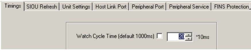
- PLC Setup settings
| Name | Function | Settings |
| Watch cycle time | A Cycle Time Too Long error (fatal error) will be registered if the cycle time exceeds the maximum setting. | 0: Default setting (1,000 ms) 1: User time setting |
| Sets the maximum cycle time. (This setting is valid only when the first setting has been set to 1.) | 0001 to 0FA0 (10 to 1,000 ms, 10-ms units) |
Note The default value for the maximum cycle time is 1,000 ms, although it can be set anywhere from 10 to 1,000 ms in 10-ms units.
- WDT(094) can be used more than once in a cycle. When WDT(094) is executed more than once the cycle time extensions are added together, although the total must not exceed 1,000 ms. If WDT(094) cannot be executed again if the cycle has already been extended to 1,000 ms.
Related Auxiliary Area Words and Bits
| Name | Address | Operation |
| Cycle Time Too Long Flag | A401.08 | ON when the present cycle time exceeds the maximum cycle time (watch cycle time) set in the PLC Setup. This is a fatal error which causes program execution to stop. |
| Maximum Cycle Time | A262 and A263 | These words contain the maximum cycle time in 32-bit binary. This value is updated every cycle. |
| Present Cycle Time | A264 and A265 | These words contain the present cycle time in 32-bit binary. This value is updated every cycle. |
Function
WDT(094) extends the maximum cycle time for the cycle in which this instruction is executed. The watchdog timer setting in the PLC Setup is extended by an interval of T × 10 ms (0 to 1,000 ms).
When it is likely that the cycle time will increase due to a temporary increase in processing data, this instruction can be used to prevent a cycle time error.
Sample program
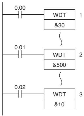
Operation of WDT(094)
In this example, the watchdog timer setting is set to 500ms.
- When CIO 0.00 turns ON, the first WDT(094) instruction extends the cycle time by 300ms (30× 10ms) Thus, the total cycle time is 800~ms at this point.
- When CIO 0.01 turns ON, the second WDT(094) instruction attempts to extend the cycle time by another 500~ms . Since the total cycle time (1,300~ms) exceeds the upper limit of 1,000~ms , the extra 300~ms is ignored. As a result, the second WDT(094) instruction actually extends the total cycle time by 200~ms .
- When CIO 0.02 turns ON, the third WDT(094) instruction attempts to extend the cycle time by another 10ms . Since the total cycle time has already reached the upper limit of 1,000ms , the third WDT(094) instruction is not executed.
3
Instruction Execution Times and Number of Steps
This section provides the execution times for all instructions used with a CP1E CPU Unit.
3-1 CP1E CPU Unit Instruction Execution Times and Number of Steps 3-2
3-1 CP1E CPU Unit Instruction Execution Times and Number of Steps
The following table lists the execution times for all instructions that are supported by the CPU Units.
The total execution time of instructions within one whole user program is the process time for program execution when calculating the cycle time (See note.).
Note User programs are allocated tasks that can be executed within cyclic tasks and interrupt tasks that satisfy interrupt conditions.
Execution times for most instructions differ depending on the CPU Unit used and the conditions when the instruction is executed.
The execution time can also vary when the execution condition is OFF.
The following table also lists the length of each instruction in the Length (steps) column. The number of steps required in the user program area for each instructions depends on the instruction and the operands used with it.
The number of steps in a program is not the same as the number of instructions.
Note 1 Most instructions are supported in differentiated form (indicated with , , @, and %). Specifying differentiation will increase the execution times by the following amounts.
(unit:s)
| Symbol | CP1E CPU Unit |
| CPU□□ | |
| ↑or ↓ | +4.0 |
| @ or % | +2.5 |
2 Use the following time as a guideline when instructions are not executed.
| CP1E CPU Unit |
| CPU□□ |
| 1.4 |
Sequence Input Instructions
| Instruction | Mnemonic | FUN No. | Length (steps) | ON execution time (μs) | Conditions |
| LOAD | LD | --- | 1 | 1.19 | --- |
| !LD | --- | 2 | 10.26 | --- | |
| LOAD NOT | LD NOT | --- | 1 | 1.19 | --- |
| !LD NOT | --- | 2 | 10.26 | --- | |
| AND | AND | --- | 1 | 1.19 | --- |
| !AND | --- | 2 | 10.26 | --- | |
| AND NOT | AND NOT | --- | 1 | 1.19 | --- |
| !AND NOT | --- | 2 | 10.26 | --- | |
| OR | OR | --- | 1 | 1.29 | --- |
| !OR | --- | 2 | 10.36 | --- | |
| OR NOT | OR NOT | --- | 1 | 1.29 | --- |
| !OR NOT | --- | 2 | 10.36 | --- | |
| AND LOAD | AND LD | --- | 1 | 0.60 | --- |
| OR LOAD | OR LD | --- | 1 | 0.60 | --- |
| NOT | NOT | 520 | 1 | 0.80 | --- |
| CONDITION ON | UP | 521 | 3 | 4.92 | --- |
| CONDITION OFF | DOWN | 522 | 4 | 5.69 | --- |
Sequence Output Instructions
| Instruction | Mnemonic | FUN No. | Length (steps) | ON execution time (μs) | Conditions |
| OUTPUT | OUT | --- | 1 | 1.61 | --- |
| !OUT | --- | 2 | 38.06 | --- | |
| OUTPUT NOT | OUT NOT | --- | 1 | 1.61 | --- |
| !OUT NOT | --- | 2 | 38.06 | --- | |
| KEEP | KEEP | 011 | 1 | 4.72 | --- |
| DIFFERENTIATE UP | DIFU | 013 | 2 | 4.12 | --- |
| DIFFERENTIATE DOWN | DIFD | 014 | 2 | 4.19 | --- |
| SET | SET | --- | 1 | 2.69 | --- |
| !SET | --- | 2 | 39.12 | --- | |
| RESET | RSET | --- | 1 | 2.69 | Word specified |
| !RSET | --- | 2 | 39.12 | --- | |
| MULTIPLE BIT SET | SETA | 530 | 4 | 17.60 | With 1-bit set |
| 253.5 | With 1,000-bit set | ||||
| MULTIPLE BIT RESET | RSTA | 531 | 4 | 17.60 | With 1-bit reset |
| 249.5 | With 1,000-bit reset | ||||
| SINGLE BIT SET | SETB | 532 | 2 | 16.60 | --- |
| !SETB | 3 | 54.60 | --- | ||
| SINGLE BIT OUTPUT | RSTB | 534 | 2 | 16.60 | --- |
| !RSTB | 3 | 54.60 | --- |
Sequence Control Instructions
| Instruction | Mnemonic | FUN No. | Length (steps) | ON execution time (μs) | Conditions |
| END | END | 001 | 1 | 4.6 | --- |
| NO OPERATION | NOP | 000 | 1 | 1.2 | --- |
| INTERLOCK | IL | 002 | 1 | 4.3 | --- |
| INTERLOCK CLEAR | ILC | 003 | 1 | 4.3 | --- |
| MULTI-INTERLOCK DIFFERENTIATION HOLD | MILH | 517 | 3 | 19.4 | During interlock |
| 19.4 | Not during interlock and interlock not set | ||||
| 21.5 | Not during interlock and interlock set | ||||
| MULTI-INTERLOCK DIFFERENTIATION RELEASE | MILR | 518 | 3 | 19.4 | During interlock |
| 19.4 | Not during interlock and interlock not set | ||||
| 21.5 | Not during interlock and interlock set | ||||
| MULTI-INTERLOCK CLEAR | MILC | 519 | 2 | 8.9 | Interlock not cleared |
| 8.9 | Interlock cleared | ||||
| JUMP | JMP | 004 | 2 | 6.1 | --- |
| JUMP END | JME | 005 | 2 | 6.2 | --- |
| CONDITIONAL JUMP | CJP | 510 | 2 | 10.1 | When JMP condition is satisfied |
| FOR LOOP | FOR | 512 | 2 | 9.7 | Designating a constant |
| BREAK LOOP | BREAK | 514 | 1 | 4.1 | --- |
| NEXT LOOP | NEXT | 513 | 1 | 5.8 | When loop is continued |
| 5.7 | When loop is ended |
Timer and Counter Instructions
| Instruction | Mnemonic | FUN No. | Length (steps) | ON execution time (μs) | Conditions |
| TIMER | TIM | --- | 3 | 11.6 | --- |
| TIMX | 550 | When loop is continued | |||
| COUNTER | CNT | --- | 3 | 11.5 | --- |
| CNTX | 546 | When loop is continued | |||
| HIGH-SPEED TIMER | TIMH | 015 | 3 | 11.6 | --- |
| TIMHX | 551 | When loop is continued | |||
| ONE-MS TIMER | TMHH | 540 | 3 | 10.8 | --- |
| TMHHX | 552 | --- | |||
| ACCUMULATIVE TIMER | TTIM | 087 | 3 | 22.7 | --- |
| 17.4 | When resetting | ||||
| 15.0 | When interlocking | ||||
| TTIMX | 555 | 3 | 22.2 | --- | |
| 17.4 | When resetting | ||||
| 15.2 | When interlocking | ||||
| LONG TIMER | TIML | 542 | 4 | 24.3 | --- |
| 20.4 | When interlocking | ||||
| TIMLX | 553 | 4 | 24.5 | --- | |
| 22.2 | When interlocking | ||||
| REVERSIBLE COUNTER | CNTR | 012 | 3 | 26.2 | --- |
| CNTRX | 548 | 25.4 | --- | ||
| RESET TIMER/ COUNTER | CNR | 545 | 3 | 19.0 | When resetting 1 word |
| 659.0 | When resetting 256 words | ||||
| CNRX | 547 | 3 | 19.0 | When resetting 1 word | |
| 659.0 | When resetting 256 words |
Comparison Instructions
| Instruction | Mnemonic | FUN No. | Length (steps) | ON execution time (μs) | Conditions |
| Input Comparison Instructions (unsigned) | LD,AND,OR+= | 300 | 4 | 9.3 | --- |
| LD,AND,OR+<> | 305 | ||||
| LD,AND,OR< | 310 | ||||
| LD,AND,OR<= | 315 | ||||
| LD,AND,OR>> | 320 | ||||
| LD,AND,OR>= | 325 | ||||
| Input Comparison Instructions (double, unsigned) | LD,AND,OR+=+L | 301 | 4 | 10.8 | --- |
| LD,AND,OR+<>+L | 306 | ||||
| LD,AND,OR+<=+L | 311 | ||||
| LD,AND,OR+<=+L | 316 | ||||
| LD,AND,OR>+L | 321 | ||||
| LD,AND,OR>=+L | 326 | ||||
| Input Comparison Instructions (signed) | LD,AND,OR+=+S | 302 | 4 | 9.4 | --- |
| LD,AND,OR+<>+S | 307 | ||||
| LD,AND,OR+<=+S | 312 | ||||
| LD,AND,OR+<=+S | 317 | ||||
| LD,AND,OR>+S | 322 | ||||
| LD,AND,OR>=+S | 327 | ||||
| Input Comparison Instructions (double, signed) | LD,AND,OR+=+SL | 303 | 4 | 10.9 | --- |
| LD,AND,OR+<>+SL | 308 | ||||
| LD,AND,OR+<=+SL | 313 | ||||
| LD,AND,OR+<=+SL | 318 | ||||
| LD,AND,OR>+SL | 323 | ||||
| LD,AND,OR>=+SL | 328 | ||||
| Time Comparison Instructions | =DT | 341 | 4 | 14.5 | --- |
| <>DT | 342 | 4 | 14.5 | --- | |
| <DT | 343 | 4 | 14.4 | --- | |
| <=DT | 344 | 4 | 14.4 | --- | |
| >DT | 345 | 4 | 14.6 | --- | |
| >=DT | 346 | 4 | 14.6 | --- | |
| COMPARE | CMP | 020 | 3 | 8.1 | --- |
| ICMP | 020 | 7 | 49.1 | --- | |
| DOUBLECOMPARE | CMPL | 060 | 3 | 9.5 | --- |
| SIGNED BINARYCOMPARE | CPS | 114 | 3 | 8.1 | --- |
| ICPS | 114 | 7 | 49.1 | --- | |
| DOUBLE SIGNED BINARYCOMPARE | CPSL | 115 | 3 | 9.5 | --- |
| TABLECOMPARE | TCMP | 085 | 4 | 61.1 | --- |
| UNSIGNED BLOCKCOMPARE | BCMP | 068 | 4 | 107.6 | --- |
| AREA RANGECOMPARE | ZCP | 088 | 3 | 17.8 | --- |
| DOUBLE AREA RANGECOMPARE | ZCPL | 116 | 3 | 20.1 | --- |
Data Movement Instructions
| Instruction | Mnemonic | FUN No. | Length (steps) | ON execution time (μs) | Conditions |
| MOVE | MOV | 021 | 3 | 8.0 | --- |
| !MOV | 021 | 7 | 57.7 | --- | |
| DOUBLE MOVE | MOVL | 498 | 3 | 8.9 | --- |
| MOVE NOT | MVN | 022 | 3 | 13.7 | --- |
| MOVE BIT | MOVB | 082 | 4 | 21.4 | --- |
| MOVE DIGIT | MOVD | 083 | 4 | 22.4 | --- |
| MULTIPLE BIT TRANSFER | XFRB | 062 | 26.4 | Transferring 1 word | |
| 137.3 | Transferring 255 bits | ||||
| BLOCK TRANSFER | XFER | 070 | 4 | 24.2 | Transferring 1 word |
| 3747.7 | Transferring 1,000 words | ||||
| BLOCK SET | BSET | 071 | 4 | 21.3 | Setting 1 word |
| 2074.4 | Setting 1,000 words | ||||
| DATA EXCHANGE | XCHG | 073 | 3 | 19.2 | --- |
| SINGLE WORD DISTRIBUTE | DIST | 080 | 4 | 20.8 | --- |
| DATA COLLECT | COLL | 081 | 4 | 20.6 | --- |
Data Shift Instructions
| Instruction | Mnemonic | FUN No. | Length (steps) | ON execution time (μs) | Conditions |
| SHIFT REGISTER | SFT | 010 | 3 | 14.1 | Shifting 1 word |
| 1076.0 | Shifting 290 words | ||||
| REVERSIBLE SHIFT REGISTER | SFTR | 084 | 4 | 18.0 | Shifting 1 word |
| 3784.4 | Shifting 1,000 words | ||||
| WORD SHIFT | WSFT | 016 | 4 | 25.8 | Shifting 1 word |
| 3783.9 | Shifting 1,000 words | ||||
| ARITHMETIC SHIFT LEFT | ASL | 025 | 2 | 13.0 | --- |
| ARITHMETIC SHIFT RIGHT | ASR | 026 | 2 | 13.0 | --- |
| ROTATE LEFT | ROL | 027 | 2 | 13.3 | --- |
| ROTATE RIGHT | ROR | 028 | 2 | 13.5 | --- |
| ONE DIGIT SHIFT LEFT | SLD | 074 | 3 | 21.8 | Shifting 1 word |
| 3778.3 | Shifting 1,000 words | ||||
| ONE DIGIT SHIFT RIGHT | SRD | 075 | 3 | 22.2 | Shifting 1 word |
| 3778.6 | Shifting 1,000 words | ||||
| SHIFT N-BITS LEFT | NASL | 580 | 3 | 19.5 | --- |
| DOUBLE SHIFT NBITS LEFT | NSLL | 582 | 3 | 20.8 | --- |
| SHIFT N-BITS RIGHT | NASR | 581 | 3 | 19.6 | --- |
| DOUBLE SHIFT NBITS RIGHT | NSRL | 583 | 3 | 21.0 | --- |
Increment/Decrement Instructions
| Instruction | Mnemonic | FUN No. | Length (steps) | ON execution time (μs) | Conditions |
| INCREMENT BINARY | ++ | 590 | 2 | 12.3 | --- |
| DOUBLE INIncrement BINARY | ++L | 591 | 2 | 13.5 | --- |
| DECREMENT BINARY | -- | 592 | 2 | 12.3 | --- |
| DOUBLE DECREMENT BINARY | --L | 593 | 2 | 13.6 | --- |
| INCREMENT BCD | ++B | 594 | 2 | 13.2 | --- |
| DOUBLE INIncrement BCD | ++BL | 595 | 2 | 14.4 | --- |
| DECREMENT BCD | --B | 596 | 2 | 13.2 | --- |
| DOUBLE DECREMENT BCD | --BL | 597 | 2 | 14.5 | --- |
Symbol Math Instructions
| Instruction | Mnemonic | FUN No. | Length (steps) | ON execution time (μs) | Conditions |
| SIGNED BINARY ADD WITHOUT CARRY | + | 400 | 4 | 11.5 | --- |
| DOUBLE SIGNED BINARY ADD WITHOUT CARRY | +L | 401 | 4 | 13.0 | --- |
| SIGNED BINARY ADD WITH CARRY | +C | 402 | 4 | 11.7 | --- |
| DOUBLE SIGNED BINARY ADD WITH CARRY | +CL | 403 | 4 | 13.2 | --- |
| BCD ADD WITHOUT CARRY | +B | 404 | 4 | 20.6 | --- |
| DOUBLE BCD ADD WITHOUT CARRY | +BL | 405 | 4 | 22.9 | --- |
| BCD ADD WITH CARRY | +BC | 406 | 4 | 20.8 | --- |
| DOUBLE BCD ADD WITH CARRY | +BCL | 407 | 4 | 23.1 | --- |
| SIGNED BINARY SUBTRACT WITHOUT CARRY | - | 410 | 4 | 11.6 | --- |
| DOUBLE SIGNED BINARY SUBTRACT WITHOUT CARRY | -L | 411 | 4 | 13.2 | --- |
| SIGNED BINARY SUBTRACT WITH CARRY | -C | 412 | 4 | 11.7 | --- |
| DOUBLE SIGNED BINARY SUBTRACT WITH CARRY | -CL | 413 | 4 | 13.3 | --- |
| BCD SUBTRACT WITHOUT CARRY | -B | 414 | 4 | 20.3 | --- |
| DOUBLE BCD SUBTRACT WITHOUT CARRY | -BL | 415 | 4 | 23.6 | --- |
| BCD SUBTRACT WITH CARRY | -BC | 416 | 4 | 20.5 | --- |
| DOUBLE BCD SUBTRACT WITH CARRY | -BCL | 417 | 4 | 23.8 | --- |
| SIGNED BINARY MULTIPLY | * | 420 | 4 | 18.4 | --- |
| DOUBLE SIGNED BINARY MULTIPLY | *L | 421 | 4 | 23.9 | --- |
| BCD MULTIPLY | *B | 424 | 4 | 22.0 | --- |
| DOUBLE BCD MULTIPLY | *BL | 425 | 4 | 33.2 | --- |
| SIGNED BINARY DIVIDE | / | 430 | 4 | 19.8 | --- |
| DOUBLE SIGNED BINARY DIVIDE | /L | 431 | 4 | 25.8 | --- |
| BCD DIVIDE | /B | 434 | 4 | 23.2 | --- |
| DOUBLE BCD DIVIDE | /BL | 435 | 4 | 33.0 | --- |
Conversion Instructions
| Instruction | Mnemonic | FUN No. | Length (steps) | ON execution time (μs) | Conditions |
| BCD TO BINARY | BIN | 023 | 3 | 15.1 | --- |
| DOUBLE BCD TO DOUBLE BINARY | BINL | 058 | 3 | 16.7 | --- |
| BINARY TO BCD | BCD | 024 | 3 | 15.1 | --- |
| DOUBLE BINARY TO DOUBLE BCD | BCDL | 059 | 3 | 17.3 | --- |
| 2'S COMPLEMENT | NEG | 160 | 3 | 14.3 | --- |
| DATA DECODER | MLPX | 076 | 4 | 19.6 | Decoding 1 digit (4 to 16) |
| 31.0 | Decoding 4 digits (4 to 16) | ||||
| 79.4 | Decoding 1 digit (8 to 256) | ||||
| 138.2 | Decoding 2 digits (8 to 256) | ||||
| DATA ENCODER | DMPX | 077 | 4 | 32.5 | Encoding 1 digit (16 to 4) |
| 63.0 | Encoding 4 digits (16 to 4) | ||||
| 68.0 | Encoding 1 digit (256 to 8) | ||||
| 112.3 | Encoding 2 digits (256 to 8) | ||||
| ASCII CONVERT | ASC | 086 | 4 | 22.8 | Converting 1 digit into ASCII |
| 24.7 | Converting 4 digits into ASCII | ||||
| ASCII TO HEX | HEX | 162 | 4 | 18.4 | Converting 1 digit |
Logic Instructions
| Instruction | Mnemonic | FUN No. | Length (steps) | ON execution time (μs) | Conditions |
| LOGICAL AND | ANDW | 034 | 4 | 18.6 | --- |
| DOUBLE LOGICAL AND | ANDL | 610 | 4 | 20.4 | --- |
| LOGICAL OR | ORW | 035 | 4 | 18.6 | --- |
| DOUBLE LOGICAL OR | ORWL | 611 | 4 | 20.4 | --- |
| EXCLUSIVE OR | XORW | 036 | 4 | 18.6 | --- |
| DOUBLE EXCLUSIVE OR | XORL | 612 | 4 | 20.4 | --- |
| COMPLEMENT | COM | 029 | 2 | 12.4 | --- |
| DOUBLE COMPLEMENT | COML | 614 | 2 | 13.6 | --- |
Special Math Instructions
| Instruction | Mnemonic | FUN No. | Length (steps) | ON execution time (μs) | Conditions |
| ARITHMETIC PROCESS | APR | 069 | 4 | 34.2 | Designating SIN and COS |
| 25.9 | Designating line-segment approximation | ||||
| BIT COUNTER | BCNT | 067 | 4 | 19.5 | Counting 1 word |
Floating-point Math Instructions
| Instruction | Mnemonic | FUN No. | Length (steps) | ON execution time (μs) | Conditions |
| FLOATING TO 16-BIT | FIX | 450 | 3 | 15.9 | --- |
| FLOATING TO 32-BIT | FIXL | 451 | 3 | 16.2 | --- |
| 16-BIT TO FLOATING | FLT | 452 | 3 | 16.2 | --- |
| 32-BIT TO FLOATING | FLTL | 453 | 3 | 17.1 | --- |
| FLOATING-POINT ADD | +F | 454 | 4 | 24.1 | --- |
| FLOATING-POINT SUBTRACT | -F | 455 | 4 | 25.2 | --- |
| FLOATING-POINT DIVIDE | /F | 457 | 4 | 25.0 | --- |
| FLOATING-POINT MULTIPLY | *F | 456 | 4 | 24.4 | --- |
| Floating Symbol Comparison | LD,AND,OR+=F | 329 | 3 | 11.6 | --- |
| LD,AND,OR+<>F | 330 | --- | |||
| LD,AND,OR+<F | 331 | --- | |||
| LD,AND,OR+<=F | 332 | --- | |||
| LD,AND,OR+>F | 333 | --- | |||
| LD,AND,OR>=F | 334 | --- | |||
| FLOATING- POINT TO ASCII | FSTR | 448 | 4 | 56.8 | --- |
| ASCII TO FLOATING-POINT | FVAL | 449 | 3 | 42.9 | --- |
Table Data Processing Instructions
| Instruction | Mnemonic | FUN No. | Length (steps) | ON execution time (μs) | Conditions |
| SWAP BYTES | SWAP | 637 | 3 | 16.8 | Swapping 1 word |
| 6250.0 | Swapping 1,000 words | ||||
| FRAME CHECKSUM | FCS | 180 | 4 | 24.1 | For 1-word table length |
| 2710.0 | For 1,000-word table length |
Data Control Instructions
| Instruction | Mnemonic | FUN No. | Length (steps) | ON execution time (μs) | Conditions |
| PID CONTROL WITH AUTOTUN-ING | PIDAT | 191 | 4 | 316.0 | Initial execution of PID processing |
| 270.0 | PID processing When sampling | ||||
| 228.0 | PID processing When not sampling | ||||
| 275.5 | Initial execution of autotuning | ||||
| 276.0 | Autotuning when sampling | ||||
| TIME-PROPORTIONAL OUTPUT | TPO | 685 | 4 | 5.8 | OFF execution time |
| 40.8 | ON execution time with duty designation or displayed output limit | ||||
| 43.4 | ON execution time with manipulated variable designation and output limit enabled | ||||
| SCALING | SCL | 194 | 4 | 24.8 | --- |
| SCALING 2 | SCL2 | 486 | 4 | 20.2 | --- |
| SCALING 3 | SCL3 | 487 | 4 | 26.4 | --- |
| AVERAGE | AVG | 195 | 4 | 24.2 | Average of an operation |
| 225.5 | Average of 64 operations |
Subroutine Instructions
| Instruction | Mnemonic | FUN No. | Length (steps) | ON execution time (μs) | Conditions |
| SUBROUTINE CALL | SBS | 091 | 2 | 6.6 | --- |
| SUBROUTINE ENTRY | SBN | 092 | 2 | 2.6 | --- |
| SUBROUTINE RETURN | RET | 093 | 1 | 3.1 | --- |
Interrupt Control Instructions
| Instruction | Mnemonic | FUN No. | Length (steps) | ON execution time (μs) | Conditions |
| SET INTERRUPT MASK | MSKS | 690 | 3 | 15.1 | Set |
| 15.1 | Reset | ||||
| CLEAR INTERRUPT | CLI | 691 | 3 | 14.9 | Set |
| 18.0 | Reset | ||||
| DISABLE INTERRUPTS | DI | 693 | 1 | 8.5 | --- |
| ENABLE INTERRUPTS | EI | 694 | 1 | 8.9 | --- |
High-speed Counter and Pulse Output Instructions
| Instruction | Mnemonic | FUN No. | Length (steps) | ON execution time (μs) | Conditions |
| MODE CONTROL | INI | 880 | 4 | 46.0 | Starting high-speed counter comparison |
| 31.8 | Stopping high-speed counter comparison | ||||
| 48.7 | Changing pulse output PV | ||||
| 35.2 | Changing high-speed counter PV | ||||
| 27.2 | Stopping pulse output | ||||
| 13.0 | Stopping PWM(891) output | ||||
| HIGH-SPEED COUNTER PV READ | PRV | 881 | 4 | 40.0 | Reading pulse output PV |
| 35.0 | Reading high-speed counter PV | ||||
| 37.2 | Reading pulse output status | ||||
| 32.6 | Reading high-speed counter status | ||||
| 24.5 | Reading PWM(891) status | ||||
| 36.5 | Reading high-speed counter range comparison results | ||||
| 29.1 | Reading frequency of high-speed counter 0 | ||||
| COMPARISON TABLE LOAD | CTBL | 882 | 4 | 69.3 | Registering target value table and starting comparison for 1 target value |
| 116.3 | Registering target value table and starting comparison for 6 target values | ||||
| 126.6 | Registering range table and starting comparison | ||||
| 46.3 | Only registering target value table for 1 target value | ||||
| 93.3 | Only registering target value table for 6 target values | ||||
| 122.5 | Only registering range table | ||||
| SPEED OUTPUT | SPED | 885 | 4 | 69.2 | Continuous mode |
| 74.0 | Independent mode | ||||
| SET PULSES | PULS | 886 | 4 | 44.1 | --- |
| PULSE OUTPUT | PLS2 | 887 | 5 | 97.6 | --- |
| ACCELERATION CONTROL | ACC | 888 | 4 | 75.6 | Continuous mode |
| 82.8 | Independent mode | ||||
| ORIGIN SEARCH | ORG | 889 | 3 | 52.2 | Origin search |
| 126.8 | Origin return | ||||
| PULSE WITH VARIABLE DUTY FACTOR | PWM | 891 | 4 | 28.9 | --- |
Step Instructions
| Instruction | Mnemonic | FUN No. | Length (steps) | ON execution time (μs) | Conditions |
| STEP DEFINE | STEP | 008 | 2 | 10.5 | Step control bit ON |
| 10.4 | Step control bit OFF | ||||
| STEP START | SNXT | 009 | 2 | 9.6 | --- |
I/O Unit Instructions
| Instruction | Mnemonic | FUN No. | Length (steps) | ON execution time (μs) | Conditions |
| I/O REFRESH | IORF | 097 | 3 | 170.7 | Refreshing 1 input word for CP1W Expansion Unit |
| 146.6 | Refreshing 1 output word for CP1W Expansion Unit | ||||
| 1725.8 | Refreshing 12 input words for CP1W Expansion Unit | ||||
| 1359.9 | Refreshing 12 output words for CP1W Expansion Unit | ||||
| 7-SEGMENT DECODER | SDEC | 078 | 4 | 21.9 | --- |
| MATRIX INPUT | MTR | 213 | 5 | 31.6 | Data input value: 00 |
| 31.6 | Data input value:FF | ||||
| 7-SEGMENT DISPLAY OUTPUT | 7SEG | 214 | 5 | 27.1 | 4 digits |
| 30.8 | 8 digits |
Serial Communications Instructions
| Instruction | Mnemonic | FUN No. | Length (steps) | ON execution time (μs) | Conditions |
| TRANSMIT | TXD | 236 | 4 | 25.0 | Sending 1 byte |
| 25.0 | Sending 256 bytes | ||||
| RECEIVE | RXD | 235 | 4 | 39.2 | Storing 1 byte |
| 256.6 | Storing 256 bytes |
Clock Instructions
| Instruction | Mnemonic | FUN No. | Length (steps) | ON execution time (μs) | Conditions |
| CALENDAR ADD | CADD | 730 | 4 | 56.6 | --- |
| CALENDAR SUBTRACT | CSUB | 731 | 4 | 55.1 | --- |
| CLOCK ADJUSTMENT | DATE | 735 | 2 | 29.9 | --- |
Failure Diagnosis Instructions
| Instruction | Mnemonic | FUN No. | Length (steps) | ON execution time (μs) | Conditions |
| FAILURE ALARM | FAL | 006 | 3 | 55.6 | Recording errors |
| 79.6 | Deleting errors (in order of priority) | ||||
| 61.6 | Deleting errors (all errors) | ||||
| 60.0 | Deleting errors (individually) | ||||
| SEVERE FAILURE ALARM | FALS | 007 | 3 | --- | --- |
Other Instructions
| Instruction | Mnemonic | FUN No. | Length (steps) | ON execution time (μs) | Conditions |
| SET CARRY | STC | 040 | 1 | 32.6 | --- |
| CLEAR CARRY | CLC | 041 | 1 | 3.9 | --- |
| EXTEND MAXIMUM CYCLE TIME | WDT | 094 | 2 | 11.7 | --- |
4
Monitoring and Computing the Cycle Time
This section describes how to monitor and calculate the cycle time of a CP1E CPU Unit that can be used in the programs.
4-1 Monitoring the Cycle Time 4-2
4-1-1 Monitoring the Cycle Time 4-2
4-2 Computing the Cycle Time 4-3
4-2-1 CPU Unit Operation Flowchart 4-3
4-2-2 Cycle Time Overview 4-4
4-2-3 I/O Refresh Times for PLC Units 4-5
4-2-4 Cycle Time Calculation Example 4-6
4-2-5 Increase in Cycle Time for Online Editing 4-6
4-1 Monitoring the Cycle Time
4-1-1 Monitoring the Cycle Time
The average, maximum, and minimum cycle times can be monitored when the CX-Programmer is connected online to a CPU Unit.
Monitoring the Average Value
While connected online to the PLC, the average cycle time is displayed in the status bar when the CPU Unit is in any mode other than PROGRAM mode.

Monitoring Maximum and Minimum Values
Select PLC Setting - PLC Information - Cycle Time from the PLC Menu.
The following PLC Cycle Time Dialog Box will be displayed.
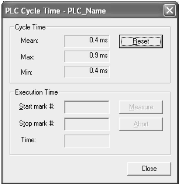
The average (mean), maximum, and minimum cycle times will be displayed in order from the top.
Click the Reset Button to recalculate and display the cycle time values.

Additional Information
The cycle time present value and maximum value are stored in the following Auxiliary Area words.
- Cycle time present value (0.1-ms increments): A264 (lower bytes) and A265 (upper bytes)
Maximum Cycle Time (0.1-ms increments): A262 (lower bytes) and A263 (upper bytes)
4-2 Computing the Cycle Time
4-2-1 CPU Unit Operation Flowchart
The CPU Unit processes data in repeating cycles from the overseeing processing up to peripheral servicing as shown in the following diagram.
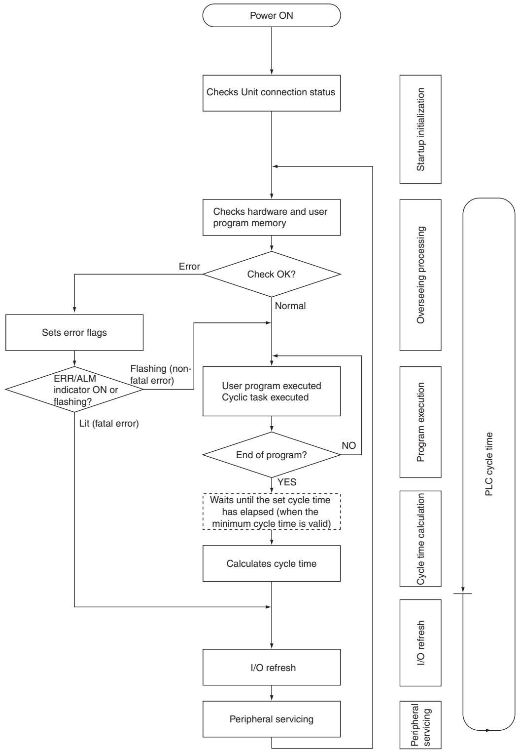
4-2-2 Cycle Time Overview
The cycle time depends on the following conditions.
- Type and number of instructions in the user program (cyclic tasks and all interrupt tasks for which the execution conditions have been satisfied)
- Type and number of CP-series Expansion Units and Expansion I/O Units
- Minimum (constant) cycle time setting in the PLC Setup
- Use of peripheral USB and serial ports

Precautions for Correct Use
When the mode is switched from MONITOR mode to RUN mode, the cycle time may be extended by 10 ms (this will not, however, cause a cycle time exceeded error).
The cycle time is the total time required for the PLC to perform the operations given in the following tables.
Cycle time = (1) + (2) + (3) + (4) + (5)
(1) Overseeing
| Operation | Processing time and fluctuation cause |
| Checks the I/O bus and user memory, checks for battery errors, etc. | 0.4 ms min. |
(2) Program Execution
| Operation | Processing time and fluctuation cause |
| Executes the instructions in the user program. The time required is the total of the executions times for all instructions. | Total instruction execution time. |
(3) Cycle Time Calculation for Minimum Cycle Time
| Operation | Processing time and fluctuation cause |
| Waits for the specified cycle time to elapse when a minimum (constant) cycle time has been set in the PLC Setup.Calculates the cycle time. | When a minimum cycle time is not set, the time for step 3 is approximately 0.When a minimum cycle time is set, the time for step 3 is the preset fixed cycle time minus the actual cycle time((1) + (2) + (4) + (5)). |
(4) I/O Refreshing
| Operation | Processing time and fluctuation cause | |
| CPU Unit built-in I/O, CPU Unit built-in analog I/O (NA-type only), CP-series Expan-sion Units and Expansion I/O Units | Outputs from the CPU Unit to the actual outputs are refreshed first for each Unit, and then inputs. | I/O refresh time for each Unit multiplied by the number of Units used. |
(5) Peripheral Servicing
| Operation | Processing time and fluctuation cause |
| Services peripheral USB port | In this servicing, 8% of the previous cycle's cycle time (calculated in step (3)) will be allowed for peripheral servicing. |
| Services serial port (Built-in RS-232C port, serial option board) |
4-2-3 I/O Refresh Times for PLC Units
- I/O Refresh Times for Built-in Analog I/O (NA-type CPU Unit only)
| Unit name | Model numbers | I/O refresh time per unit | |
| NA-type CPU Unit | 20-point I/O + Analog I/OCPU Unit | CP1E-NA20D□-□ | 0.5 ms |
Note No matter whether use analog I/O function or not, the I/O refresh time is the same.
- I/O Refresh Times for CP-series Expansion Units and Expansion I/O Units
| Unit name | Model numbers | I/O refresh time per unit | |
| Expansion I/O Unit | 8-point Input Unit | CP1W-8ED | 0.14 ms |
| 8-point Output Unit | CP1W-8ER | 0.06 ms | |
| CP1W-8ET | |||
| CP1W-8ET1 | |||
| 16-point Output Unit | CP1W-16ER | 0.17 ms | |
| CP1W-16ET | |||
| CP1W-16ET1 | |||
| 20-point I/O Unit | CP1W-20EDR1 | 0.20 ms | |
| CP1W-20EDT | |||
| CP1W-20EDT1 | |||
| 32-point Output Unit | CP1W-32ER | 0.33 ms | |
| CP1W-32ET | |||
| CP1W-32ET1 | |||
| 40-point I/O Unit | CP1W-40EDR | 0.45 ms | |
| CP1W-40EDT | |||
| CP1W-40EDT1 | |||
| Expansion Unit | Analog Input Unit | CP1W-AD041 | 0.72 ms |
| Analog Output Unit | CP1W-DA041 | 0.33 ms | |
| Analog I/O Units | CP1W-MAD11 | 0.36 ms | |
| Temperature Sensor Unit | CP1W-TS001 | 0.30 ms | |
| CP1W-TS002 | 0.57 ms | ||
| CP1W-TS101 | 0.30 ms | ||
| CP1W-TS102 | 0.57 ms | ||
| CompoBus/S I/O Link Unit | CP1W-SRT21 | 0.20 ms | |

Additional Information
The I/O refresh time for the built-in I/O of the CPU Unit is included in overseeing processing.
4-2-4 Cycle Time Calculation Example
The following example shows the method used to calculate the cycle time when Expansion I/O Units are connected to a CP1E CPU Unit.
- Conditions
| Item | Description | |
| CP1E CPU Unit | 40-point I/O Unit CP1W-40EDR | 1 Unit |
| Ladder diagram | 5K steps | LD instructions: 2.5K steps OUT instructions: 2.5K steps |
| Peripheral USB port connection | Yes or no | |
| Minimum cycle time processing | None | |
| Serial port connection | None | |
| Other peripheral servicing | None | |
- Calculation Example
| Process name | Equation | Processing time | |
| Peripheral USB port connected | Peripheral USB port not connected | ||
| (1)Overseeing | - | 0.4 ms | 0.4 ms |
| (2)Program execution | 1.19μs×2,500+1.61μs×2,500 | 7.0 ms | 7.0 ms |
| (3)Cycle time calculation | (Minimum cycle time not set.) | 0 ms | 0 ms |
| (4)I/O refreshing | 0.45 ms | 0.45 ms | 0.45 ms |
| (5)Peripheral servicing | (Only peripheral USB port connected) | 0.2 ms | 0 ms |
| Cycle time | (1)+(2)+(3)+(4)+(5) | 8.15 ms | 7.85 ms |
4-2-5 Increase in Cycle Time for Online Editing
When online editing is executed to change the program from the CX-Programmer while the CPU Unit is operating in MONITOR mode, the CPU Unit will momentarily suspend operation while the program is being changed. The cycle time is extended by the writing programs for the CPU Unit. And the schedule task will not be executed while the CPU Unit suspends operation.
If the program size is 8K steps, the cycle time extension will be as follows:
| CPU Unit | Increase in cycle time for online editing |
| CP1E CPU Unit | Maximum: 16 ms, Normal: 6 ms (for a program size of 8K steps) |
When editing online, the cycle time will be extended and the schedule task execution may be delayed or become abnormal according to the editing that is performed.
Appendices
Alphabetical List of Instructions by Mnemonic A-2
Alphabetical List of Instructions by Mnemonic
A
| Mne-monic | Instruction | FUN No. | Upward differen-tiation | Downward differen-tion | Immediate refreshing specifica-tion | Page |
| ACC | ACCELER-ATIONCONTROL | 888 | @ACC | --- | --- | 2-331 |
| AND | AND | --- | @AND | %AND | IAND | 2-9 |
| ANDLD | AND LOAD | --- | --- | --- | --- | 2-13 |
| ANDNOT | AND NOT | --- | --- | --- | IANDNOT | 2-9 |
| AND< | AND LESS THAN | 310 | --- | --- | --- | 2-88 |
| AND<= | AND LESS THAN OR EQUAL | 315 | --- | --- | --- | 2-88 |
| AND<=F | ANDFLOATINGLESS THANOR EQUAL | 332 | --- | --- | --- | 2-241 |
| AND<=DT | AND TIMELESS THANOR EQUAL | 344 | --- | --- | --- | 2-91 |
| AND<=L | AND DOU-BLE LESS THANOR EQUAL | 316 | --- | --- | --- | 2-88 |
| AND<=S | ANDSIGNEDLESS THANOR EQUAL | 317 | --- | --- | --- | 2-88 |
| AND<=SL | AND DOU-BLE SIGNEDLESS THANOR EQUAL | 318 | --- | --- | --- | 2-88 |
| AND<> | AND NOTEQUAL | 305 | --- | --- | --- | 2-88 |
| AND<>DT | AND TIMENOTEQUAL | 342 | --- | --- | --- | 2-91 |
| AND<>F | ANDFLOATINGNOTEQUAL | 330 | --- | --- | --- | 2-241 |
| AND<>L | AND DOU-BLE NOTEQUAL | 306 | --- | --- | --- | 2-88 |
| AND<>S | ANDSIGNEDNOTEQUAL | 307 | --- | --- | --- | 2-88 |
| AND<>SL | AND DOU-BLE SIGNEDNOTEQUAL | 308 | --- | --- | --- | 2-88 |
| AND<>DT | AND TIMELESS THAN | 343 | --- | --- | --- | 2-91 |
| Mne-monic | Instruction | FUN No. | Upward differen-tiation | Downward differentia-tion | Immediate refreshing specifica-tion | Page |
| AND<F | AND FLOATING LESS THAN | 331 | --- | --- | --- | 2-241 |
| AND<L | AND DOU-BLE LESS THAN | 311 | --- | --- | --- | 2-88 |
| AND<S | AND SIGNED LESS THAN | 312 | --- | --- | --- | 2-88 |
| AND<SL | AND DOU-BLE SIGNED LESS THAN | 313 | --- | --- | --- | 2-88 |
| AND= | AND EQUAL | 300 | --- | --- | --- | 2-88 |
| AND=DT | AND TIME EQUAL | 341 | --- | --- | --- | 2-91 |
| AND=F | AND FLOATING EQUAL | 329 | --- | --- | --- | 2-241 |
| AND=L | AND DOU-BLE EQUAL | 301 | --- | --- | --- | 2-88 |
| AND=S | AND SIGNED EQUAL | 302 | --- | --- | --- | 2-88 |
| AND=SL | AND DOU-BLE SIGNED EQUAL | 303 | --- | --- | --- | 2-88 |
| AND> | AND GREATER THAN | 320 | --- | --- | --- | 2-88 |
| AND>= | AND GREATER THAN OR EQUAL | 325 | --- | --- | --- | 2-88 |
| AND>=DT | AND TIME GREATER THAN OR EQUAL | 346 | --- | --- | --- | 2-91 |
| AND>=F | AND FLOATING GREATER THAN OR EQUAL | 334 | --- | --- | --- | 2-241 |
| AND>=L | AND DOU-BLE GREATER THAN OR EQUAL | 326 | --- | --- | --- | 2-88 |
| AND>=S | AND SIGNED GREATER THAN OR EQUAL | 327 | --- | --- | --- | 2-88 |
| AND>=SL | AND DBL SIGNED GREATER THAN OR EQUAL | 328 | --- | --- | --- | 2-88 |
| AND>DT | AND TIME GREATER THAN | 345 | --- | --- | --- | 2-91 |
| AND>F | AND FLOATING GREATER THAN | 333 | --- | --- | --- | 2-241 |
| AND>L | AND DOU-BLE GREATER THAN | 321 | --- | --- | --- | 2-88 |
| AND>S | AND SIGNED GREATER THAN | 322 | --- | --- | --- | 2-88 |
| AND>SL | AND DOU-BLE SIGNED GREATER THAN | 323 | --- | --- | --- | 2-88 |
| ANDL | DOUBLE LOGICAL AND | 610 | @ANDL | --- | --- | 2-210 |
| ANDW | LOGICAL AND | 034 | @ANDW | --- | --- | 2-210 |
| APR | ARITH-METIC PROCESS | 069 | @APR | --- | --- | 2-218 |
| ASC | ASCII CON-VERT | 086 | @ASC | --- | --- | 2-201 |
| ASL | ARITH-METIC SHIFT LEFT | 025 | @ASL | --- | --- | 2-133 |
| ASR | ARITH-METIC SHIFT RIGHT | 026 | @ASR | --- | --- | 2-134 |
| AVG | AVERAGE | 195 | --- | --- | --- | 2-287 |
B
| Mne-monic | Instruction | FUN No. | Upward differen-tiation | Downward differentia-tion | Immediate refreshing specifica-tion | Page |
| BCD | BINARY TO BCD | 024 | @BCD | --- | --- | 2-187 |
| BCDL | DOUBLE BINARY TO DOUBLE BCD | 059 | @BCDL | --- | --- | 2-187 |
| BCMP | BLOCK COMPARE | 068 | @BCMP | --- | --- | 2-103 |
| BCNT | BIT COUNTER | 067 | @BCNT | --- | --- | 2-227 |
| BIN | BCD TO BINARY | 023 | @BIN | --- | --- | 2-185 |
| Mne-monic | Instruction | FUN No. | Upward differen-tiation | Downward differenta-tion | Immediate refreshing specifica-tion | Page |
| BINL | DOUBLE BCD TO DOUBLE BINARY | 058 | @BINL | --- | --- | 2-185 |
| BREAK | BREAK LOOP | 514 | --- | --- | --- | 2-59 |
| BSET | BLOCK SET | 071 | @BSET | --- | --- | 2-119 |
C
| Mne-monic | Instruction | FUN No. | Upward differen-tiation | Downward differenta-tion | Immediate refreshing specifica-tion | Page |
| CADD | CALEN-DAR ADD | 730 | @ CADD | --- | --- | 2-380 |
| CJP | CONDI-TIONAL JUMP | 510 | --- | --- | --- | 2-53 |
| CLC | CLEAR CARRY | 041 | @ CLC | --- | --- | 2-398 |
| CLI | CLEAR INTER-RUPT | 691 | @ CLI | --- | --- | 2-303 |
| CMP | COMPARE | 020 | --- | --- | !CMP | 2-95 |
| CMPL | DOUBLE COMPARE | 060 | --- | --- | --- | 2-95 |
| CNR | RESET TIMER/COU NTER | 545 | @ CNR | --- | --- | 2-86 |
| CNRX | RESET TIMER/COU NTER | 547 | @ CNRX | --- | --- | 2-86 |
| CNT | COUNTER | --- | --- | --- | --- | 2-80 |
| CNTR | REVERS-IBLE COUNTER | 012 | --- | --- | --- | 2-83 |
| CNTRX | REVERS-IBLE COUNTER | 548 | --- | --- | --- | 2-83 |
| CNTX | COUNTER | 546 | --- | --- | --- | 2-80 |
| COLL | DATA COL-LECT | 081 | @ COLL | --- | --- | 2-125 |
| COM | COMPLE-MENT | 029 | @ COM | --- | --- | 2-216 |
| COML | DOUBLE COMPLE-MENT | 614 | @ COML | --- | --- | 2-216 |
| CPS | SIGNED BINARY COMPARE | 114 | --- | --- | !CPS | 2-98 |
| CPSL | DOUBLE SIGNED BINARY-COMPARE | 115 | --- | --- | --- | 2-98 |
| CSUB | CALEN-DAR SUB-TRACT | 731 | @ CSUB | --- | --- | 2-380 |
| CTBL | REGISTER-COMPARI-SON TABLE | 882 | @ CTBL | --- | --- | 2-315 |
D
| Mne-monic | Instruction | FUN No. | Upward differen-tiation | Downward differentia-tion | Immediate refreshing specifica-tion | Page |
| DATE | CLOCK ADJUST-MENT | 735 | @DATE | --- | --- | 2-385 |
| DI | DISABLE INTER-RUPTS | 693 | @DI | --- | --- | 2-306 |
| DIFD | DIFFEREN-TIATE DOWN | 014 | --- | --- | !DIFD | 2-27 |
| DIFU | DIFFEREN-TIATE UP | 013 | --- | --- | !DIFU | 2-25 |
| DIST | SINGLE WORD DISTRIBUTION | 080 | @DIST | --- | --- | 2-123 |
| DMPX | DATA ENCODER | 077 | @DMPX | --- | --- | 2-196 |
| DOWN | CONDI-TION OFF | 522 | --- | --- | --- | 2-17 |
| DSW | DIGITAL SWITCH INPUT | 210 | --- | --- | --- | 2-357 |
E
| Mne-monic | Instruction | FUN No. | Upward differen-tiation | Downward differentia-tion | Immediate refreshing specifica-tion | Page |
| EI | ENABLE INTER-RUPTS | 694 | --- | --- | --- | 2-307 |
| END | END | 001 | --- | --- | --- | 2-38 |
F
| Mne-monic | Instruction | FUN No. | Upward differen-tiation | Downward differentia-tion | Immediate refreshing specifica-tion | Page |
| FAL | FAILURE ALARM | 006 | @FAL | --- | --- | 2-387 |
| FALS | SEVERE FAILURE ALARM | 007 | --- | --- | --- | 2-393 |
| FCS | FRAME CHECK-SUM | 180 | @FCS | --- | --- | 2-255 |
| FIX | FLOATING TO 16-BIT | 450 | @FIX | --- | --- | 2-233 |
| FIXL | FLOATING TO 32-BIT | 451 | @FIXL | --- | --- | 2-233 |
| FLT | 16-BIT TO FLOATING | 452 | @FLT | --- | --- | 2-235 |
| FLTL | 32-BIT TO FLOATING | 453 | @FLTL | --- | --- | 2-235 |
| Mne-monic | Instruction | FUN No. | Upward differen-tiation | Downward differentia-tion | Immediate refreshing specifica-tion | Page |
| FOR | --- | 512 | --- | --- | --- | 2-56 |
| FSTR | FLOATING-POINT TO ASCII | 448 | @FSTR | --- | --- | 2-244 |
| FVAL | ASCII TO FLOATING-POINT | 449 | @FVAL | --- | --- | 2-249 |
H
| Mne-monic | Instruction | FUN No. | Upward differen-tiation | Downward differentia-tion | Immediate refreshing specifica-tion | Page |
| HEX | ASCII TO HEX | 162 | @HEX | --- | --- | 2-205 |
1
| Mne-monic | Instruction | FUN No. | Upward differen-tiation | Downward differentia-tion | Immediate refreshing specifica-tion | Page |
| INI | MODE CONTROL | 880 | @INI | --- | --- | 2-308 |
| IORF | I/O REFRESH | 097 | @IORF | --- | --- | 2-352 |
J
| Mne-monic | Instruction | FUN No. | Upward differen-tiation | Downward differentia-tion | Immediate refreshing specifica-tion | Page |
| JME | JUMP END | 005 | --- | --- | --- | 2-53 |
| JMP | JUMP | 004 | --- | --- | --- | 2-53 |
K
| Mne-monic | Instruction | FUN No. | Upward differen-tiation | Downward differentia-tion | Immediate refreshing specifica-tion | Page |
| KEEP | KEEP | 011 | --- | --- | !KEEP | 2-21 |
L
| Mne-monic | Instruction | FUN No. | Upward differen-tiation | Downward differentia-tion | Immediate refreshing specifica-tion | Page |
| LD | LOAD | --- | @LD | %LD | !LD | 2-7 |
| LD=DT | LOAD DATE EQUAL | 341 | --- | --- | --- | 2-91 |
| LD=S | LOAD SIGNED EQUAL | 302 | --- | --- | --- | 2-88 |
| Mine- monic | Instruction | FUN differenti- tion | Downward immediate speci- cia- | Page |
| LD NOT | LOAD NOT | ... | ... | ... |
| LD= | LOAD LESS | 310 | ... | ... |
| LD= | LOAD LESS | 315 | ... | ... |
| LD= | LOAD LESS | 315 | ... | ... |
| LD= | LOAD LESS | 344 | ... | ... |
| LD= | LOAD LESS | 344 | ... | ... |
| LD= | LOAD LESS | 344 | ... | ... |
| LD= | LOAD LESS | 344 | ... | ... |
| LD= | LOAD LESS | 344 | ... | ... |
| LD= | LOAD LESS | 344 | ... | ... |
| LD= | LOAD LESS | 344 | ... | 2.88 |
| LD= | LOAD LESS | 344 | ... | 2.88 |
| LD= | LOAD LESS | 344 | ... | 2.88 |
| LD= | LOAD LESS | 344 | ... | 2.88 |
| LD= | LOAD LESS | 344 | ... | 2.88 |
| LD= | LOAD LESS | 344 | ... | 2.88 |
| LD=S | LOAD S | 317 | ... | ... |
| LD=F | LOAD F | 318 | ... | ... |
| LD=F | LOAD F | 318 | ... | ... |
| LD=F | LOAD F | 318 | ... | ... |
| LD=F | LOAD F | 318 | ... | ... |
| LD=F | LOAD F | 318 | ... | ... |
| LD=F | LOAD F | 318 | ... | ... |
| LD=F | LOAD F | 318 | ... | 2.88 |
| LD=F | LOAD F | 318 | ... | 2.88 |
| LD=F | LOAD F | 318 | ... | 2.88 |
| LD=F | LOAD F | 318 | ... | 2.88 |
| LD=F | LOAD F | 318 | ... | 2.88 |
| LD=F | LOAD F | 318 | ... | 2.88 |
| LD=S | LOAD S | 317 | ... | ... |
| LD=S | LOAD S | 317 | ... | ... |
| LD=S | LOAD S | 317 | ... | ... |
| LD=S | LOAD S | 317 | ... | ... |
| LD=S | LOAD S | 317 | ... | ... |
| LD=S | LOAD S | 317 | ... | ... |
| LD=S | LOAD S | 317 | ... | ... |
| LO= | LOAD LO= | 313 | ... | ... |
| LE= | LOAD LO= | 313 | ... | ... |
| LE= | LOAD LO= | 313 | ... | 2.88 |
| LE= | LOAD LO= | 313 | ... | 2.88 |
| LE= | LOAD LO= | 313 | ... | 2.88 |
| LE= | LOAD LO= | 313 | ... | 2.88 |
| LE= | LOAD LO= | 313 | ... | 2.88 |
| LE= | LOAD LO= | 313 | ... | 2.8 |
| LE= | LOAD LO= | 313 | ... | 2.88 |
| LE= | LOAD LO= | 313 | ... | 2.88 |
| LE= | LOAD LO= | 313 | ... | 2.88 |
| LE= | LOAD LO= | 313 | ... | 2.88 |
| LE= | LOAD LO= | 313 | ... | 2.91 |
| LE= | LOAD LO= | 313 | ... | 2.91 |
| LE= | LOAD LO= | 313 | ... | 2.91 |
| LE= | LOAD LO= | 313 | ... | 2.91 |
| LE= | LOAD LO= | 313 | ... | 2.91 |
| LE= | LOAD LO= | 313 | ... | 2.9 |
| Mine-monie | FUM | Upward differentia-tion | Downward refining specia-ation | Immediate Page | |||||
| Load | FLOATING | LOAD DOU | 329 | LOAD DOU | 329 | LOAD DOU | 329 | ||
| LD=F | FLOATING | LOAD | BLE | 303 | -- | -- | -- | 2.241 | |
| Ld=L | LOAD DOU | 301 | -- | -- | -- | -- | 2.88 | ||
| LD=SL | LOAD DOU | 303 | -- | -- | -- | -- | 2.88 | ||
| LD=SL | LOAD DOU | 301 | -- | -- | -- | -- | 2.88 | ||
| LD=SL | LOAD DOU | 301 | -- | -- | -- | -- | 2.88 | ||
| LD=SL | LOAD DOU | 301 | -- | -- | -- | -- | 2.88 | ||
| LD=SL | LOAD DOU | 301 | -- | -- | -- | -- | 2.8 | ||
| LD=SL | LOAD DOU | 301 | -- | -- | -- | -- | 2.88 | ||
| LD=SL | LOAD DOU | 301 | -- | -- | -- | -- | 2.88 | ||
| LD=SL | LOAD DOU | 301 | -- | -- | -- | -- | 2.88 | ||
| LD=SL | LOAD DO U | 301 | -- | -- | -- | -- | 2.88 | ||
| LD=SL | LOAD DOU | 301 | -- | -- | -- | -- | 2.88 | ||
| LD=SL | LOAD DOU | 301 | -- | -- | -- | -- | 2.88 | ||
| LD=SL | LOAD DOU | 301 | -- | -- | -- | -- | |||
| LD=SL | LOAD DOU | 301 | -- | -- | -- | -- | |||
| LD=SL | LOAD DOU | 301 | -- | -- | -- | -- | |||
| LD=SL | LOAD DOU | 301 | -- | -- | -- | -- | |||
| LD=SL | LOAD DOU | 301 | -- | -- | -- | -- | 2.88 | ||
| LD=SL | LOAD DOU | 301 | -- | -- | -- | -- | |||
| LD=SL | LOAD DOU | 301 | -- | -- | -- | -- | |||
| LD=SL | LOAD DOU | 301 | -- | -- | |||||
| LD=SL | LOAD DOU | 301 | -- | -- | |||||
| LD=SL | LOAD DOU | 301 | -- | -- | |||||
| LD=SL | LOAD DOU | 301 | -- | -- | |||||
| LD=SL | LOAD DOU | 301 | -- | -- | |||||
| LD= SL | LOAD DOU | 301 | -- | -- | |||||
| LD=SL | LOAD DOU | 301 | -- | -- | |||||
| LD=SL | LOAD DOU | 301 | -- | -- | |||||
| LD=SL | LOAD DOU | 301 | -- | -- | |||||
| LD=SL | LOAD DOU | 3 01 | -- | -- | |||||
| LD=SL | LOAD DOU | 301 | -- | -- | |||||
| LD=SL | LOAD DOU | 301 | -- | -- | |||||
| LD=SL | LOAD DOU | 301 | -- | -- | |||||
| LD=SL | LOAD DOU | 301 | -- | -- | 2.88 | ||||
| LD=SL | LOAD DOU | 301 | -- | -- | |||||
| LD=SL | LOAD DOU | 301 | -- | -- | |||||
| LD=SL | LOAD DOU | 301 | -- | -- | |||||
| LD=SL | LOAD DOU | 301 | -- | -- | |||||
| LD= S | LOAD DOU | 301 | -- | -- | |||||
| LD= S | LOAD DOU | 301 | -- | -- | |||||
| LD= S | LOAD DOU | 301 | -- | -- | |||||
| LD= S | LOAD DOU | 301 | -- | -- | |||||
| LD= S | LOAD DOU | 3 01 | -- | -- | |||||
| LD= S | LOAD DOU | 301 | -- | -- | |||||
| LD= S | LOAD DOU | 301 | -- | -- | |||||
| LD= S | LOAD DOU | 301 | -- | -- | |||||
| LD= S | LOAD DOU | 301 | -- | -- | 2.88 | ||||
| LD= S | LOAD DOU | 301 | -- | -- | |||||
| LD= S | LOAD DOU | 301 | -- | -- | |||||
| LD= S | LOAD DOU | 301 | -- | -- | |||||
| LD= S | LOAD DOU | 301 | -- | -- | |||||
| LD= F | FLOATING | 328 | -- | -- | |||||
| LD= F | FLOATING | 328 | -- | -- | |||||
| LD= F | FLOATING | 328 | -- | -- | |||||
| LD= F | FLOATING | 328 | -- | -- | |||||
| LD= F | FLOATING | 328 | -- | -- | |||||
| LO= F | FLOATING | 328 | -- | -- | |||||
| LO= F | FLOATING | 328 | -- | -- | |||||
| LO= F | FLOATING | 328 | -- | -- | |||||
| LO= F | FLOATING | 328 | -- | -- | |||||
| LO= F | FLOATING | 328 | - | - | |||||
| LO= F | FLOATING | 328 | - | - | |||||
| LO= F | FLOATING | 328 | - | - | |||||
| LO= F | FLOATING | 328 | - | - | |||||
| LO= F | FLOATING | 328 | - | - | |||||
| LO= F | |||||||||
M
| Mne-monic | Instruction | FUN No. | Upward differen-tiation | Downward differentia-tion | Immediate refreshing specifica-tion | Page |
| MILC | MULTI-INTER-LOCK CLEAR | 519 | --- | --- | --- | 2-44 |
| MILH | MULTI-INTER-LOCK DIFFERENTIAT IONHOLD | 517 | --- | --- | --- | 2-44 |
| MILR | MULTI-INTER-LOCK DIFFERENTIAT IONRE-LEASE | 518 | --- | --- | --- | 2-44 |
| MLPX | DATA DECODER | 076 | @MLPX | --- | --- | 2-191 |
| MOV | MOVE | 021 | @MOV | --- | !MOV | 2-108 |
| MOVB | MOVE BIT | 082 | @MOVB | --- | --- | 2-111 |
| MOVD | MOVE DIGIT | 083 | @MOVD | --- | --- | 2-113 |
| MOVL | DOUBLE MOVE | 498 | @MOVL | --- | --- | 2-108 |
| MSKS | SET INTER-RUPT MASK | 690 | @MSKS | --- | --- | 2-300 |
| MTR | MATRIX INPUT | 213 | --- | --- | --- | 2-361 |
| MVN | MOVE NOT | 022 | @MVN | --- | --- | 2-108 |
N
| Mne-monic | Instruction | FUN No. | Upward differen-tiation | Downward differentia-tion | Immediate refreshing specifica-tion | Page |
| NASL | SHIFT N-BITS LEFT | 580 | @NASL | --- | --- | 2-141 |
| NASR | SHIFT N-BITS RIGHT | 581 | @NASR | --- | --- | 2-144 |
| NEG | 2'S COM-PLEMENT | 160 | @NEG | --- | --- | 2-189 |
| NEXT | --- | 513 | --- | --- | --- | 2-56 |
| NOP | NO OPER-A-TION | 000 | --- | --- | --- | 2-39 |
| NOT | NOT | 520 | --- | --- | --- | 2-16 |
| NSLL | DOUBLE SHIFT N-BITS LEFT | 582 | @NSLL | --- | --- | 2-141 |
| NSRL | DOUBLE SHIFT N-BITSRIGHT | 583 | @NSRL | --- | --- | 2-144 |
0
| Mne-monic | Instruction | FUN No. | Upward differen-tiation | Downward differen-tion | Immediate refreshing specifica-tion | Page |
| OR | OR | --- | @OR | %OR | !OR | 2-11 |
| ORG | ORIGIN SEARCH | 889 | @ORG | --- | --- | 2-336 |
| OR LD | OR LOAD | --- | --- | --- | --- | 2-13 |
| OR NOT | OR NOT | --- | --- | --- | !OR NOT | 2-11 |
| OR< | OR LESS THAN | 310 | --- | --- | --- | 2-88 |
| OR<= | OR LESS THAN OR EQUAL | 315 | --- | --- | --- | 2-88 |
| OR<=DT | OR DATE LESS THAN OR EQUAL | 344 | --- | --- | --- | 2-91 |
| OR<=F | OR FLOATING LESS THAN OR EQUAL | 332 | --- | --- | --- | 2-241 |
| OR<=L | OR DOUBLE LESS THAN OR EQUAL | 316 | --- | --- | --- | 2-88 |
| OR<=S | OR SIGNED LESS THAN OR EQUAL | 317 | --- | --- | --- | 2-88 |
| OR<=SL | OR DOUBLE SIGNED LESS THAN OR EQUAL | 318 | --- | --- | --- | 2-88 |
| OR<> | OR NOT EQUAL | 305 | --- | --- | --- | 2-88 |
| OR<>DT | OR DATE NOT EQUA | 342 | --- | --- | --- | 2-91 |
| OR<>F | OR FLOAT-ING NOT EQUAL | 330 | --- | --- | --- | 2-241 |
| OR<>L | OR DOUBLE NOT EQUAL | 306 | --- | --- | --- | 2-88 |
| OR<>S | OR SIGNED NOT EQUAL | 307 | --- | --- | --- | 2-88 |
| OR<>SL | OR DOUBLE SIGNED NOT EQUAL | 308 | --- | --- | --- | 2-88 |
| OR<DT | OR DATE LESS THAN | 343 | --- | --- | --- | 2-91 |
| OR<F | OR FLOATING LESS THAN | 331 | --- | --- | --- | 2-241 |
| OR<L | OR DOUBLE LESS THAN | 311 | --- | --- | --- | 2-88 |
| OR<S | OR SIGNED LESS THAN | 312 | --- | --- | --- | 2-88 |
| OR<SL | OR DOUBLE SIGNED LESS THAN | 313 | --- | --- | --- | 2-88 |
| Mine- monic | Instruction | FUN different- tion | Downward immediate specification | Page |
| OR= OR EQUAL | OR or EQUAL | 300 | ... | 248 |
| OR=DT | OR or EQUAL | 341 | ... | 291 |
| OR=F | FLOATING | 329 | ... | 241 |
| OR=F | FLOATING | 329 | ... | 241 |
| OR=F | FLOATING | 329 | ... | 241 |
| OR=F | FLOATING | 329 | ... | 241 |
| OR=F | FLOATING | 329 | ... | 241 |
| OR=F | FLOATING | 329 | ... | 241 |
| OR=F | FLOATING | |||
| OR=L | DOUBLE | 301 | ... | 288 |
| OR=L | DOUBLE | 301 | ... | 288 |
| OR=L | DOUBLE | 301 | ... | 288 |
| OR=L | DOUBLE | 301 | ... | 288 |
| OR=L | DOUBLE | 301 | ... | 288 |
| OR=L | DOUBLE | 301 | ... | 288 |
| OR=L | DOUBLE | 301 | ... | 17 |
| OR=L | DOUBLE | 301 | ... | 17 |
| OR=L | DOUBLE | 301 | ... | 17 |
| OR=L | DOUBLE | 301 | ... | 17 |
| OR=L | DOUBLE | 301 | ... | 17 |
| OR=L | DOUBLE | 301 | ... | 17 |
| OR=L | DOUBLE | 301 | ... | 17 |
| ORG-S | DOUBLE | 301 | ... | 288 |
| ORG-S | DOUBLE | 301 | ... | 288 |
| ORG-S | DOUBLE | 301 | ... | 288 |
| ORG-S | DOUBLE | 301 | ... | 288 |
| ORG-S | DOUBLE | 301 | ... | 288 |
| ORG-S | DOUBLE | 301 | ... | 288 |
| ORG-S | DOUBLE | 301 | ... | 17 |
| ORG-S | DOUBLE | 301 | ... | 17 |
| ORG-S | DOUBLE | 301 | ... | 17 |
| ORG-S | DOUBLE | 301 | ... | 17 |
| ORG-S | DOUBLE | 301 | ... | 17 |
| ORG-S | DOUBLE | 301 | ... | 17 |
| ORG-S | DOUBLE | 301 | ... | 17 |
| OR+S | DOUBLE | 321 | ... | 288 |
| OR+S | DOUBLE | 321 | ... | 288 |
| OR+S | DOUBLE | 321 | ... | 288 |
| OR+S | DOUBLE | 321 | ... | 288 |
| OR+S | DOUBLE | 321 | ... | 288 |
| OR+S | DOUBLE | 321 | ... | 288 |
| OR+S | DOUBLE | 321 | ... | 17 |
| OR+S | DOUBLE | 321 | ... | 17 |
| OR+S | DOUBLE | 321 | ... | 17 |
| OR+S | DOUBLE | 321 | ... | 17 |
| OR+S | DOUBLE | 321 | ... | 17 |
| OR+S | DOUBLE | 321 | ... | 17 |
| OR+S | DOUBLE | 321 | ... | 17 |
| ORG-S | DOUBLE | 321 | ... | 288 |
| ORG-S | DOUBLE | 321 | ... | 288 |
| ORG-S | DOUBLE | 321 | ... | 288 |
| ORG-S | DOUBLE | 321 | ... | 288 |
| ORG-S | DOUBLE | 321 | ... | 288 |
| ORG-S | DOUBLE | 321 | ... | 288 |
| ORG-S | DOUBLE | 321 | ... | 17 |
| ORG-S | DOUBLE | 321 | ... | 17 |
| ORG-S | DOUBLE | 321 | ... | 17 |
| ORG-S | DOUBLE | 321 | ... | 17 |
| ORG-S | DOUBLE | 321 | ... | 17 |
| ORG-S | DOUBLE | 321 | ... | 17 |
| ORG-S | DOUBLE | 321 | ... | 17 |
| OR+S | DOUBLE | 321 | ... | 288 |
| OR+S | DOUBLE | 321 | ... | 288 |
| OR+S | DOUBLE | 321 | ... | 288 |
| OR+S | DOUBLE | 321 | ... | 288 |
| OR+S | DOUBLE | 321 | ... | 288 |
| OR+S | DOUBLE | 17 | ... | 288 |
| Mine-monie | Instruction | FUN | Upward differentia-tion | Downward refining speci-cas- | Immediate Page |
| ORWL | DOUBLE | 611 | @ORWL | ... | 2.212 |
| LOGICAL | |||||
| OUT | OUTPUT | ... | ... | ... | |
| NOT | OUTPUT | ... | ... | ... | |
| NOT | ... | ... | ... |
P
| PUDAT | PID CON- | 191 | ... | ... | 2.257 |
| TROL | 881 | @PRV | ... | 2.325 | |
| WITHAUTO- | 887 | @PLS2 | ... | 2.325 | |
| TUNING | 887 | @PLS2 | ... | 2.325 | |
| PLS2 | 887 | @PLS2 | ... | 2.325 | |
| PULSE | 887 | @PLS2 | ... | 2.325 | |
| OUTPUT | 887 | @PLS2 | ... | 2.325 | |
| PRV | 881 | @PRV | ... | 2.311 | |
| HIGH- | 881 | @PRV | ... | 2.311 | |
| CPEED- | 886 | @PLS | ... | 2.323 | |
| COUNTER | 886 | @PLS | ... | 2.323 | |
| PV READ | 886 | @PLS | ... | 2.323 | |
| PULS | 886 | @PLS | ... | 2.323 | |
| PULSE | 886 | @PLS | ... | 2.323 | |
| FACTOR | 886 | @PLS | ... | 2.323 |
R
| Mone-monique | FUN | Upward differentia-tion | Downward immediate-species- | Page |
| RET | TIN | RETURN | ||
| ROL | ROTATE | 027 | @ROL | 2.295 |
| ROR | RIGHT | 028 | @ROR | 2.135 |
| RSET | RESET | ... | @SET | 2.29 |
| RSTA | MULTIPLE | 531 | @RSTA | 2.31 |
| RSTB | RESET | 533 | @RSTB | 2.33 |
| RXD | RECEIVE | 235 | @RXD | 2.374 |
s
| Mne-monic | Instruction | FUN No. | Upward differen-tiation | Downward differentia-tion | Immediate refreshing specifica-tion | Page |
| SBN | SUBROU-TINE ENTRY | 092 | --- | --- | --- | 2-295 |
| SBS | SUBROU-TINE CALL | 091 | @SBS | --- | --- | 2-290 |
| SCL | SCALING | 194 | @SCL | --- | --- | 2-276 |
| SCL2 | SCALING 2 | 486 | @SCL2 | --- | --- | 2-280 |
| SCL3 | SCALING 3 | 487 | @SCL3 | --- | --- | 2-284 |
| SDEC | 7-SEG-MENT DECODER | 078 | @SDEC | --- | --- | 2-354 |
| SET | SET | --- | @SET | %SET | !SET | 2-29 |
| SETA | MULTIPLE BIT SET | 530 | @SETA | --- | --- | 2-31 |
| SETB | SINGLE BIT SET | 532 | @SETB | --- | !SETB | 2-33 |
| SFT | SHIFT REGISTER | 010 | --- | --- | --- | 2-127 |
| SFTR | REVERS-IBLE SHIFT REGISTER | 084 | @SFTR | --- | --- | 2-129 |
| SLD | ONE DIGIT SHIFT LEFT | 074 | @SLD | --- | --- | 2-139 |
| SNXT | STEP START | 009 | --- | --- | --- | 2-342 |
| SPED | SPEED OUTPUT | 885 | @SPED | --- | --- | 2-319 |
| SRD | ONE DIGIT SHIFT RIGHT | 075 | @SRD | --- | --- | 2-139 |
| STC | SET CARRY | 040 | @STC | --- | --- | 2-398 |
| STEP | STEP DEFINE | 008 | --- | --- | --- | 2-342 |
| SWAP | SWAP BYTES | 637 | @SWAP | --- | --- | 2-253 |
T
| Mne-monic | Instruction | FUN No. | Upward differen-tiation | Downward differentia-tion | Immediate refreshing specifica-tion | Page |
| TCMP | TABLE COMPARE | 085 | @TCMP | --- | --- | 2-101 |
| TIM | HUNDRED-MS TIMER | --- | --- | --- | --- | 2-66 |
| TIMH | TEN-MS TIMER | 015 | --- | --- | --- | 2-69 |
| TIMHX | TEN-MS TIMER | 551 | --- | --- | --- | 2-69 |
| TIML | LONG TIMER | 542 | --- | --- | --- | 2-77 |
| TIMLX | LONG TIMER | 553 | --- | --- | --- | 2-77 |
| TIMX | HUNDRED-MS TIMER | 550 | --- | --- | --- | 2-66 |
| TMHH | ONE-MS TIMER | 540 | --- | --- | --- | 2-72 |
| Mne-monic | Instruction | FUN No. | Upward differen-tiation | Downward differentia-tion | Immediate refreshing specifica-tion | Page |
| TMHHX | ONE-MS TIMER | 552 | --- | --- | --- | 2-72 |
| TPO | TIME-PRO-PORTION-ALOUTPUT | 685 | --- | --- | --- | 2-269 |
| TR | TR Bits | --- | --- | --- | --- | 2-20 |
| TTIM | ACCUMU-LATIVE TIMER | 087 | --- | --- | --- | 2-74 |
| TTIMX | ACCUMU-LATIVE TIMER | 555 | --- | --- | --- | 2-74 |
| TXD | TRANSMIT | 236 | @TXD | --- | --- | 2-369 |
U
| Mne-monic | Instruction | FUN No. | Upward differen-tiation | Down- ward dif-ferentiatio n | Immedi- ate refreshing specifica-tion | Page |
| UP | CONDI-TION ON | 521 | --- | --- | --- | 2-17 |
W
| Mne-monic | Instruction | FUN No. | Upward differen-tiation | Downward differentia-tion | Immediate refreshing specifica-tion | Page |
| WDT | EXTEND MAXIMUM-CYCLE TIME | 094 | @WDT | --- | --- | 2-399 |
| WSFT | WORD SHIFT | 016 | @WSFT | --- | --- | 2-131 |
X
| Mne-monic | Instruction | FUN No. | Upward differen-tiation | Downward differentia-tion | Immediate refreshing specifica-tion | Page |
| XCHG | DATA EXCHANGE | 073 | @XCHG | --- | --- | 2-121 |
| XFER | BLOCK TRANSFER | 070 | @XFER | --- | --- | 2-117 |
| XFRB | MULTIPLE BIT TRANS-FER | 062 | @XFRB | --- | --- | 2-115 |
| XORL | DOUBLE EXCLU-SIVE OR | 612 | @XORL | --- | --- | 2-214 |
| XORW | EXCLU-SIVE OR | 036 | @XORW | --- | --- | 2-214 |
Z
| Mne-monic | Instruction | FUN No. | Upward differen-tiation | Downward differentia-tion | Immediate refreshing specifica-tion | Page |
| ZCP | AREA RANGE COM-PARE | 088 | --- | --- | --- | 2-105 |
| ZCPL | DOUBLE AREA RANGE-COMPARE | 116 | --- | --- | --- | 2-105 |
Symbol
| Mne-monic | Instruction | FUN No. | Upward differen-tiation | Downward differen-tion | Immediate refreshing specifica-tion | Page |
| 7SEG | 7-SEG-MENT DIS-PLAY OUTPUTU | 214 | --- | --- | --- | 2-365 |
| + | SIGNED BINARY ADDWITH-OUT CARRY | 400 | @+ | --- | --- | 2-158 |
| ++ | INCREASENMENT BINARY | 590 | @++ | --- | --- | 2-147 |
| ++B | INCREASENMENT BCD | 594 | @++B | --- | --- | 2-153 |
| ++BL | DOUBLE INCREASENMENT BCD | 595 | @++BL | --- | --- | 2-153 |
| ++L | DOUBLE INCREASENMENTBI-NARY | 591 | @++L | --- | --- | 2-147 |
| +B | BCD ADD WITHOUT CARRY | 404 | @+B | --- | --- | 2-162 |
| +BC | BCD ADD WITH CARRY | 406 | @+BC | --- | --- | 2-164 |
| +BCL | DOUBLE BCD ADD WITH-CARRY | 407 | @+BCL | --- | --- | 2-164 |
| +BL | DOUBLE BCD ADD WITHOUT-CARRY | 405 | @+BL | --- | --- | 2-162 |
| +C | SIGNED BINARY ADD WITH-CARRY | 402 | @+C | --- | --- | 2-160 |
| +CL | DOUBLE SIGNED BINARY-ADD WITH CARRY | 403 | @+CL | --- | --- | 2-160 |
| +F | FLOATING-POINT ADD | 454 | @+F | --- | --- | 2-237 |
| Mne-monic | Instruction | FUN No. | Upward differen-tiation | Downward differenta-tion | Immediate refreshing specifica-tion | Page |
| +L | DOUBLE SIGNED BINARY- ADD WITH- OUT CARRY | 401 | @+L | --- | --- | 2-158 |
| - | SIGNED BINARY SUB- TRACTWIT HOUT CARRY | 410 | @- | --- | --- | 2-166 |
| -- | DECRE-MENT BINARY | 592 | @-- | --- | --- | 2-150 |
| --B | DECRE-MENT BCD | 596 | @--B | --- | --- | 2-156 |
| --BL | DOUBLE DECRE-MENT BCD | 597 | @--BL | --- | --- | 2-156 |
| --L | DECRE-MENT BINARY | 593 | @--L | --- | --- | 2-150 |
| -B | BCD SUB-TRACT WITHOUT- CARRY | 414 | @-B | --- | --- | 2-172 |
| -BC | BCD SUB-TRACT WITH- CARRY | 416 | @-BC | --- | --- | 2-175 |
| -BCL | DOUBLE BCD SUB-TRACTWIT H CARRY | 417 | @-BCL | --- | --- | 2-175 |
| -BL | DOUBLE BCD SUB-TRACTWIT HOUT CARRY | 415 | @-BL | --- | --- | 2-172 |
| -C | SIGNED BINARY SUB-TRACTWIT H CARRY | 412 | @-C | --- | --- | 2-170 |
| -CL | DOUBLE SIGNED BINA- RYSUB- TRACTWIT H CARRY | 413 | @-CL | --- | --- | 2-170 |
| -F | FLOATING- POINT SUBTRACT | 455 | @-F | --- | --- | 2-237 |
| -L | DOUBLE SIGNED BINA- RYSUB- TRACT WITHOUT- CARRY | 411 | @-L | --- | --- | 2-166 |
| * | SIGNED BINARY MULTIPLY | 420 | @* | --- | --- | 2-177 |
| *B | BCD MULTI- PLY | 424 | @*B | --- | --- | 2-179 |
| *BL | DOUBLE BCD MULTI-PLY | 425 | @*BL | --- | --- | 2-179 |
| *F | FLOATING-POINT MULTIPLY | 456 | @*F | --- | --- | 2-237 |
| *L | DOUBLE SIGNED BINARY-MULTIPLY | 421 | @*L | --- | --- | 2-177 |
| / | SIGNED BINARY DIVIDE | 430 | @/ | --- | --- | 2-181 |
| /B | BCD DIVIDE | 434 | @/B | --- | --- | 2-183 |
| /BL | DOUBLE BCD DIVIDE | 435 | @/BL | --- | --- | 2-183 |
| /F | FLOATING-POINT DIVIDE | 457 | @/F | --- | --- | 2-237 |
| /L | DOUBLE SIGNED BINARYDI-VIDE | 431 | @/L | --- | --- | 2-181 |
ASCII Code Table
A manual revision code appears as a suffix to the catalog number on the front cover of the manual.
Cat. No. W483-E1-03

| Revision code | Date | Revised content |
| 01 | March 2009 | Original production |
| 02 | June 2009 | Errors were corrected. |
| 03 | January 2010 | Information added on E10/14, N14/60 and NA20 CPU Units. |
OMRON Corporation Industrial Automation Company
Tokyo, JAPAN
Contact: www.ja.omron.com
Regional Headquarters
OMRON EUROPE B.V.
OMRON ELECTRONICS LLC
One Commerce Drive Schaumburg,
IL 60173-5302 U.S.A.
Tel: (1) 847-843-7900/Fax: (1) 847-843-7787
OMRON ASIA PACIFIC PTE. LTD.
No. 438A Alexandra Road # 05-05/08 (Lobby 2),
Alexandra Technopark,
Singapore 119967
Tel: (65) 6835-3011/Fax: (65) 6835-2711
Room 2211, Bank of China Tower,
200 Yin Cheng Zhong Road,
PuDong New Area, Shanghai, 200120, China
Tel: (86) 21-5037-2222/Fax: (86) 21-5037-2200
Authorized Distributor:
© OMRON Corporation 2009 All Rights Reserved. In the interest of product improvement,
specifications are subject to change without notice.
- INSTRUCTIONS REFERENCE MANUAL
- OMRON, 2009
- SYSMAC CP Series
- Introduction
- Intended Audience
- Applicable Products
- - CP-series CP1E CPU Units
- CP1E CPU Unit Manuals
- Manual Configuration
- CP1E CPU Unit Instructions Reference Manual (Cat. No. W483) (This Manual)
- CP1E CPU Unit Software User's Manual (Cat. No. W480)
- Manual Structure
- Page Structure and Icons
- Special Information
- Sections in this Manual
- CONTENTS
- Section 1 Summary of Instructions 1-1
- Section 2 Instructions 2-1
- Comparison Instructions 2-88
- Data Movement Instructions 2-108
- Data Shift Instructions 2-127
- Increment/Decrement Instructions 2-147
- Symbol Math Instructions 2-158
- Conversion Instructions 2-185
- Logic Instructions 2-210
- Special Math Instructions 2-218
- Floating-point Math Instructions 2-229
- Table Data Processing Instructions 2-253
- Data Control Instructions 2-257
- Subroutines Instructions 2-290
- Interrupt Control Instructions 2-298
- High-speed Counter/Pulse Output Instructions 2-308
- Step Instructions 2-341
- Basic I/O Unit Instructions 2-352
- Serial Communication Instructions 2-369
- Clock Instructions 2-380
- Failure Diagnosis Instructions 2-387
- Section 3 Instruction Execution Times and Number of Steps ... 3-1
- Section 4 Monitoring and Computing the Cycle Time. 4-1
- Section A Appendices .A-1
- Read and Understand this Manual
- Warranty and Limitations of Liability
- WARRANTY
- LIMITATIONS OF LIABILITY
- Application Considerations
- Disclaimers
- Safety Precautions
- Definition of Precautionary Information
- Symbols
- Caution
- Precautions for Safe Use
- - Handling
- - External Circuits
- Regulations and Standards
- Trademarks
- Related Manuals
- 1
- Summary of Instructions
- 1-1 Summary of Instructions
- 2
- Instructions
- Notation and Layout of Instruction Descriptions
- Constants
- Operand Descriptions and Operand Specifications
- Examples
- Condition Flags
- Symbol Instructions
- Sequence Input Instructions
- Differentiated and Immediate Refreshing Instructions
- Operation Timing for I/O Instructions
- LD/LD NOT
- Applicable Program Areas
- Operands
- -Operand Specifications
- Flags
- Function
- LD
- - LD NOT
- Hint
- Precautions
- Sample program
- AND/AND NOT
- AND
- AND NOT
- OR/OR NOT
- OR
- OR NOT
- AND LD/OR LD
- AND LD
- OR LD
- NOT
- UP/DOWN
- UP
- DOWN
- Sequence Output Instructions
- OUT/OUT NOT
- OUT
- OUT NOT
- TR
- Using TR0 to TR15
- KEEP
- DIFU
- - Operand Specifications
- DIFD
- SET/RSET
- - SET
- - RSET
- SETA/RSTA
- - SETA
- RSTA
- SETB/RSTB
- - SETB
- RSTB
- Sequence Control Instructions
- Overview of Interlock Instructions
- - Interlock Instructions
- - Differences between Interlocks and Multiple Interlocks
- - Differences between MILH(517) and MILR(518)
- - Differences between Interlocks and Jumps
- END
- NOP
- IL/ILC
- Operation of Differentiated Instructions
- Example:
- Reference:
- MILH/MILR/MILC
- N: Interlock Number
- D: Interlock Status Bit
- - Interlock Status
- - Nesting
- Example 1
- Example 2
- - Operation of Differentiated Instructions in an MILH(517) Interlock
- Example
- - Operation of Differentiated Instructions in an MILR(518) Interlock
- - Controlling Interlock Status from a Programming Device
- JMP/CJP/JME
- N: Jump Number
- JMP/CJP
- JME
- JMP
- CJP
- N: Number of loops
- BREAK
- Timer and Counter Instructions
- Refresh Methods for Timer/Counter PV
- - Overview
- - Applicable Instructions
- - Setting method for PV refresh
- Basic Timer Specifications
- - Example Timer and Counter Applications
- Example 1: Long-term Timers
- 1) Two TIM Instructions
- 2) TIM and CNT Instructions
- 3) Clock Pulse and CNT Instruction
- Example 2: Two-stage Counter
- Example 3: ON/OFF Delay
- Example 4: One-shot Bit
- Example 5: Flicker Bit 1) Two TIM Instructions
- 2) Clock Pulse
- - Timer reset method
- Turn OFF the execution condition for the timer instruction.
- Use the RESET TIMER/COUNTER instruction.
- N: Timer Number
- S: Set Value (100-ms Units)
- TIMH/TIMHX
- S: Set Value
- TIML/TIMLX
- D1: Completion Flag
- D2: PV Word
- S:SV Word
- N: Counter Number
- N1: First Number in Range
- N2: Last Number in Range
- Comparison Instructions
- - Options
- AND LESS THAN: AND<(310)
- AND SIGNED LESS THAN: AND<312>
- C: Control Word
- S_1 through S_1 + 2 : Present Time Data
- S_2 through S_2 + 2 : Comparison Time Data
- - Masking Time Values
- - CMP
- - CMPL
- - CPS
- - CPSL
- TCMP
- T: First word of table
- R: Result word
- BCMP
- B: First word of block
- ZCP
- ZCPL
- Data Movement Instructions
- MOV/MOVL/MVN
- MOV
- - MOVL
- MVN
- MOVB
- MOVD
- S: Source Word
- D: Destination Word
- - Example of transferring multiple digits
- XFRB
- D: First destination Word
- S: First Source Word
- XFER
- N: Number of Words
- BSET
- St: Starting Word
- E: End Word
- XCHG
- DIST
- Bs: Destination Base Address
- Of: Offset
- COLL
- Bs: Source Base Address
- Data Shift Instructions
- SFT
- - Shift Register Exceeding 16 Bits
- SFTR
- - Shifting Data
- - Controlling Data
- Resetting Data
- Shifting Data Left (from Rightmost to Leftmost Bit)
- Shifting Data Right (from Leftmost to Rightmost Bit)
- WSFT
- ASL
- ASR
- ROL
- ROR
- SLD/SRD
- SLD
- SRD
- NASL/NSLL
- - NASL
- NSLL
- NASR/NSRL
- - NASR
- NSRL
- Increment/Decrement Instructions
- Operation of + + (590) / + + L(591)
- Operation of @++(590)/@++L(591)
- Operation of --(592)/--L(593)
- Operation of @--(592)/@@L(593)
- + + B
- + + BL
- Operation of ++B(594)/++BL(595)
- - Operation of @ ++B(594)/@ ++BL(595)
- --B/--BL
- B
- - --BL
- Operation of --B(596)/--BL(597)
- - Operation of @--B(596)/@@BL(597)
- Symbol Math Instructions
- + / + L
- +BC/+BCL
- 2's Complement
- Subtraction at (1)
- Subtraction at (2)
- Final Subtraction Result
- 10's Complement
- -BC/-BCL
- -BC
- - BCL
- *L
- *B/*BL
- 1, /L
- /B
- /BL
- Conversion Instructions
- BIN/BINL
- BIN
- BINL
- BCD/BCDL
- S: Source Word (BCD)/First Source Word (BCDL)
- BCD
- BCDL
- NEG
- - NEG
- MLPX
- - 4-to-16 bit decoder
- R: First Result Word
- 8-to-256 bit conversion
- - 4-to-16 bit Conversion
- - 8-to-256 bit Conversion
- Precaution
- - Example of multi-digit decoding
- DMPX
- 16-to-4 bit conversion
- 256-to-8 bit conversion
- - 256-to-8 bit Conversion
- DI: Digit Designator
- - Parity
- Examples of Di
- HEX
- - Output example
- - Example of converting multiple bytes of ASCII code to hex
- Logic Instructions
- ANDW/ANDL
- ANDW
- - ANDL
- ORW
- ORWL
- XORW/XORL
- XORW
- XORL
- COM/COML
- COM
- COML
- Special Math Instructions
- APR
- Sine Function
- - Cosine Function
- - Linear Extrapolation Function
- Operation of the Linear Extrapolation Function
- - 16-bit Unsigned BCD Data
- - 16-bit Unsigned Binary Data
- - 16-bit Signed Binary Data
- - 32-bit Signed Binary Data
- - Sine Function (C: #0000)
- - Cosine Function (C: #0001)
- - Linear Extrapolation (C: Word Address)
- BCNT
- Floating-point Math Instructions
- Data Format
- Number of Digits
- - Floating-point Data
- - Special Numbers
- - Writing Floating-point Data
- - Numbers Expressed as Floating-point Values
- Normalized Numbers
- Non-normalized Numbers
- Zero
- Infinity
- NaN
- - Floating-point Arithmetic Results
- Rounding Results
- Overflows, Underflows, and Illegal Calculations
- Precautions in Handling Special Values
- - Floating-point Calculation Results
- FIX/FIXL
- FIX
- Example conversions:
- - FIXL
- FLT/FLTL
- - FLT
- - FLTL
- Operation rules
- - FLOATING-POINT ADD (+F)
- - FLOATING-POINT SUBTRACT (-F)
- - FLOATING-POINT MULTIPLY (*F)
- - FLOATING-POINT DIVIDE (/F)
- FSTR
- C: First Control Word
- Storage of ASCII Text
- Decimal notation (C=0 hex)
- Scientific notation (C=1 hex)
- - Limits on the Number of ASCII Characters
- - Converting to ASCII Text in Decimal Notation
- - Converting to ASCII Text in Scientific Notation
- FVAL
- - Storage of ASCII Text
- ASCII Character Storage
- Decimal notation
- Scientific notation
- - Converting ASCII Text in Decimal Notation to Floating-point Data
- - Converting ASCII Text in Scientific Notation
- Table Data Processing Instructions
- SWAP
- R1: First word in range
- FCS
- Data Control Instructions
- PIDAT
- C: First Parameter Word
- Autotuning
- PID Control
- Calculation Method
- Block Diagram for Target Value PID with Two Degrees of Freedom
- PID Parameter Settings
- Sampling Period and Cycle Time
- Proportional Action (P)
- - Integral Action (I)
- - Derivative Action (D)
- PID Action
- Direction of Action
- Adjusting PID Parameters
- - Interrupting PID Control to Perform Autotuning
- - Starting PIDAT(191) with Autotuning
- - Interrupting Autotuning Before Completion
- TPO
- S: Input Word
- R: Pulse Output Bit
- - Combining TPO(685) with a PID Control Instruction
- - External Wiring Example
- Parameter Settings
- Execution
- Combining TPO(685) with PIDAT(191)
- Using TPO(685) Alone
- SCL
- P1: First Parameter Word
- Reverse Scaling
- - Scaling 1 to 5-V Analog Input to 0 to 300
- - Scaling 1 to 5-V Analog Input to -200 to 200
- AVG
- N: Number of Cycles
- R: Result First Word and R+1: First Work Area Word
- Subroutines Instructions
- SBS
- N: Subroutine number
- Combined-use instructions
- - Sequential (Non-nested) Subroutines
- - Nested Subroutines
- - SBN
- RET
- Interrupt Control Instructions
- Outline of Interrupt Control Instructions
- - SET INTERRUPT MASK: MSKS(690)
- CLEAR INTERRUPT: CLI(691)
- - DISABLE INTERRUPTS: DI(693)
- - ENABLE INTERRUPTS: EI(694)
- Precautions in Using Interrupt Tasks
- - Precautions for All Interrupts
- - Precautions for I/O Interrupts
- - Precautions for Scheduled Interruptions
- MSKS
- I/O Interrupt Task
- Resetting and Starting Scheduled Interrupts
- Examples for Input Interrupts
- - Example for Scheduled Interrupts
- CLI
- Clearing/Retaining an I/O Interrupt Task's Recorded Interrupt Inputs
- Setting the Time to the First Scheduled Interrupts
- Clearing/Retaining High-speed Counter Interrupts
- N = 102 to 107: Clearing Interrupt Inputs
- N = 4 : Setting the Time to the First Scheduled Interrupt Task
- N = 10 or 15: Clearing High-speed Counter Interrupts
- - Example for Input Interrupts
- - Example for First Scheduled Interrupts
- - Example for High-speed Counter Interrupts
- DI
- E
- High-speed Counter/Pulse Output Instructions
- INI
- P: Port Specifier
- NV: First Word with New PV
- - Starting Comparison (C = 0000 hex)
- - Stopping Comparison (C = 0001 hex)
- - Stopping Pulse Output ( P = 0000 , 0001 or 1000 hex and C = 0003 hex)
- PRV
- C: Control Data
- - Reading a PV ( C = 0000 hex)
- - Reading Status (C = 0001 hex)
- - Reading the Results of Range Comparison (C = 0002 hex)
- - Reading Pulse Output or High-speed Counter Frequency (C = 00□3 hex)
- - Pulse Frequency Calculation Methods
- CTBL
- TB: First comparison table word
- - Registering a Comparison Table (C = 0002 or 0003 hex)
- - Registering a Comparison Table and Starting Comparison (C = 0000 or 0001 hex)
- - Stopping Comparison
- - Target Value Comparison
- - Range Comparison
- SPED
- M: Output mode
- F: First pulse frequency word
- Continuous Mode Speed Control
- - Independent Mode Positioning
- PULS
- T: Pulse type
- N and N+1: Number of pulses
- Note
- PLS2
- S: First Word of Settings Table
- F: First Word of Starting Frequency
- ACC
- Note Triangular Control
- ORG
- - Origin Search (Bits 12 to 15 of C = 0 hex)
- - Origin Return (Bits 12 to 15 of C = 1 hex)
- PWM
- F: Frequency
- D: Duty Factor
- Step Instructions
- SNXT/STEP
- SNXT(009)
- Starting Step Execution
- Proceeding to the Next Step
- Ending the Step Programming Area
- - STEP(008)
- Starting a Step
- Interlock Status (IL)
- Ending the Step Program Area
- Related Bits
- Additional Information:
- Application Examples
- Explanation of operation
- Additional Information
- Basic I/O Unit Instructions
- IORF
- Units Refreshed by IORF(097)
- Refreshing Words in the I/O Bit Area
- SDEC
- - 7-segment Data
- DSW
- I: Input Word (Data Line D0 to D3 Inputs)
- O: Output Word (CS/RD Control Signal Outputs)
- D: First Result Word
- C1: Number of Digits
- C2: System Word
- - External Connections
- - Timing Chart
- MTR
- I: Input Word
- O: Output Word (Selection Signal Outputs)
- D: First Register Word
- C: System Word
- 7SEG
- O: Output Word (Data and Latch Outputs)
- D: System Word
- Serial Communication Instructions
- TXD
- Related Auxiliary Area Words and Bits
- CPU Unit's Built-in RS-232C Port
- - Serial Option Board Port
- Related PLC Setup Settings
- - Start code / end code settings and send data
- - Sending Data to a Code Reader
- Communications Settings
- Programming Example
- - Controlling Signals
- RXD
- - Start Code/End Code Settings and Receive Data
- - Receiving data
- Controlling Signals
- Clock Instructions
- CADD/CSUB
- CADD
- CSUB
- Sample program CADD
- DATE
- Failure Diagnosis Instructions
- FAL
- - Generating or Clearing User-defined Non-fatal Errors
- - Generating Non-fatal System Errors
- - Auxiliary Area Words/Flags for User-defined Errors Only
- - Auxiliary Area Words/Flags for System Errors Only
- - Auxiliary Area Words/Flags for both User-defined and System Errors
- Clearing Non-fatal Errors without a Programming Device
- - Clearing User-defined Non-fatal Errors
- - Clearing Non-fatal System Errors
- - Generating Non-fatal User-defined Errors
- - Disabling Error Log Entries of User-defined Errors
- - Displaying Messages with Non-fatal User-defined Errors
- - Generating a Non-fatal Error
- - Clearing a Particular Non-fatal Error
- - Clearing All Non-fatal Errors
- - Clearing the Most Serious Non-fatal Error
- - Generating a Non-fatal System Error
- FALS
- - Generating User-defined Fatal Errors
- - Generating Fatal Errors from the System
- - Generating Fatal User-defined Errors
- - Displaying Messages with Fatal User-defined Errors
- - Clearing FALS(007) Fatal System Errors
- - Clearing FALS(007) User-defined Fatal Errors
- - Generating a User-defined Error
- Other Instructions
- STC/CLC
- STC
- - CLC
- WDT
- T: Timer setting
- CX-Programmer settings
- - PLC Setup settings
- Operation of WDT(094)
- 3
- Instruction Execution Times and Number of Steps
- 3-1 CP1E CPU Unit Instruction Execution Times and Number of Steps
- I/O Unit Instructions
- Serial Communications Instructions
- 4
- Monitoring and Computing the Cycle Time
- 4-1 Monitoring the Cycle Time
- 4-1-1 Monitoring the Cycle Time
- Monitoring the Average Value
- Monitoring Maximum and Minimum Values
- 4-2 Computing the Cycle Time
- 4-2-1 CPU Unit Operation Flowchart
- 4-2-2 Cycle Time Overview
- Precautions for Correct Use
- Peripheral Servicing
- 4-2-3 I/O Refresh Times for PLC Units
- - I/O Refresh Times for Built-in Analog I/O (NA-type CPU Unit only)
- - I/O Refresh Times for CP-series Expansion Units and Expansion I/O Units
- 4-2-4 Cycle Time Calculation Example
- - Conditions
- - Calculation Example
- 4-2-5 Increase in Cycle Time for Online Editing
- Appendices
- Alphabetical List of Instructions by Mnemonic
Brand : OMRON
Model : CP1E
Category : Programmable Controllers