900 - Kitchen hood ROBLIN - Free user manual and instructions
Find the device manual for free 900 ROBLIN in PDF.
User questions about 900 ROBLIN
0 question about this device. Answer the ones you know or ask your own.
Ask a new question about this device
Download the instructions for your Kitchen hood in PDF format for free! Find your manual 900 - ROBLIN and take your electronic device back in hand. On this page are published all the documents necessary for the use of your device. 900 by ROBLIN.
USER MANUAL 900 ROBLIN
Instructions for use and installation
Cooker Hood

GB Instructions Manual INDEX
RECOMMENDATIONS AND SUGGESTIONS 11
CHARACTERISTICS 12
INSTALLATION 14
USE 16
MAINTENANCE 17
FR Manuel d'Instructions SOMMAIRE
CONSEILS ET SUGGESTIONS 19
CHARACTERISTIQUES 20
INSTALLATION 22
UTILISATION 24
ENTRETIEN 25
- The manufacturer will not be held liable for any damages resulting from incorrect or improper installation.
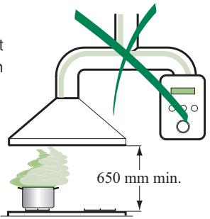
- The minimum safety distance between the cooker top and the extractor hood is 650~mm .
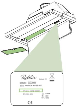
- Check that the mains voltage corresponds to that indicated on the rating plate xed to the inside of the hood.
- For Class I appliances, check that the domestic power supply guaran tees adequate earthing.
Connect the extractor to the exhaust ue through a pipe of minimum diameter 150~mm . The route of the ue must be as short as possible.
- Do not connect the extractor hood to exhaust ducts carrying combustion fumes (boilers, replaces, etc.).
- If the extractor is used in conjunction with non-electrical appliances (e.g. gas burning appliances), a sufficient degree of aeration must be guaranteed in the room in order to prevent the back ow of exhaust gas. The kitchen must have an opening communicating directly with the open air in order to guarantee the entry of clean air.
USE
- The extractor hood has been designed exclusively for domestic use to eliminate kitchen smells.
- Never use the hood for purposes other than for which it has been designed.
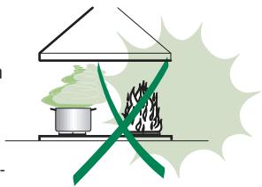
- Never leave high naked ames under the hood when it is in operation.
- Adjust the ame intensity to direct it onto the bottom of the pan only, making sure that it does not engulf the sides.
- Deep fat fryers must be continuously monitored during use: overheated oil can burst into ames.
- Do not ambê under the range hood; risk of re
- The hood should not be used by children or persons not instructed in its correct use.
MAINTENANCE
- Switch or unplug the appliance from the mains supply before carrying out any maintenance work.
- Clean and/or replace the Filters after the speci ed time period.
- Clean the hood using a damp cloth and a neutral liquid detergent.
The symbol on the product or on its packaging indicates that this product may not be treated as household waste. Instead it shall be handed over to the applicable collection point for the recycling of electrical and electronic equipment. By ensuring this product is disposed of correctly, you will help prevent potential negative consequences for the environment and human health, which could otherwise be caused by inappropriate waste handling of this product. For more detailed information about recycling of this product, please contact your local city office, your household waste disposal service or the shop where you purchased the product.
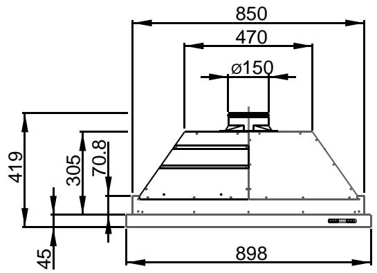
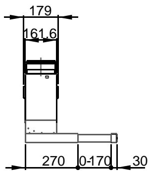
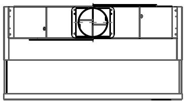
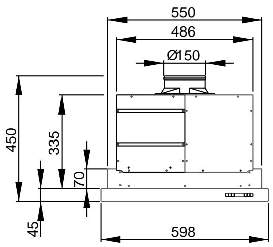
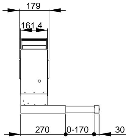
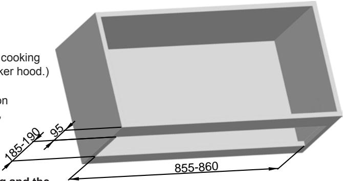
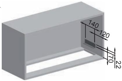
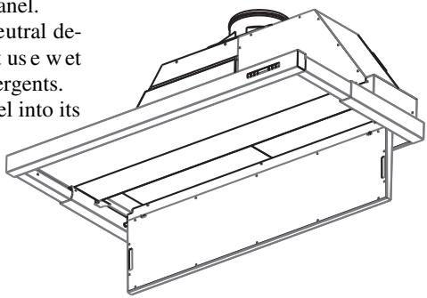
Dimensions
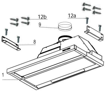
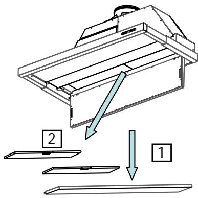
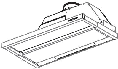
Components
| Ref. | Q.ty | Product Components |
| 1 | 1 | Hood Body, complete with: Controls, Light, Blower, Filters |
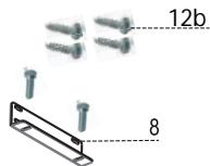
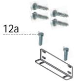
| 8 | 2 | square xing brackets |
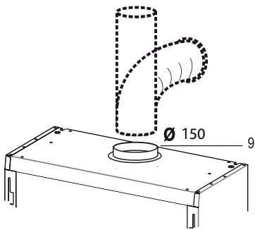
| 9 | 1 | Flangeø 150 mm |
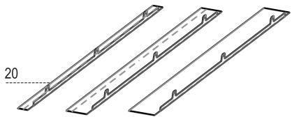
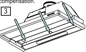
| 20 | 3 | Closing element |
| Ref. | Q.ty | Installation Components |
| 12a | 8 | Screws 4 x 16 |
| 12b | 4 | Screws M5 x 16 |
| 12c | 3 | Screws 3,5 x 9,5 |
Q.ty Documentation
1 Instruction Manual
12c
600
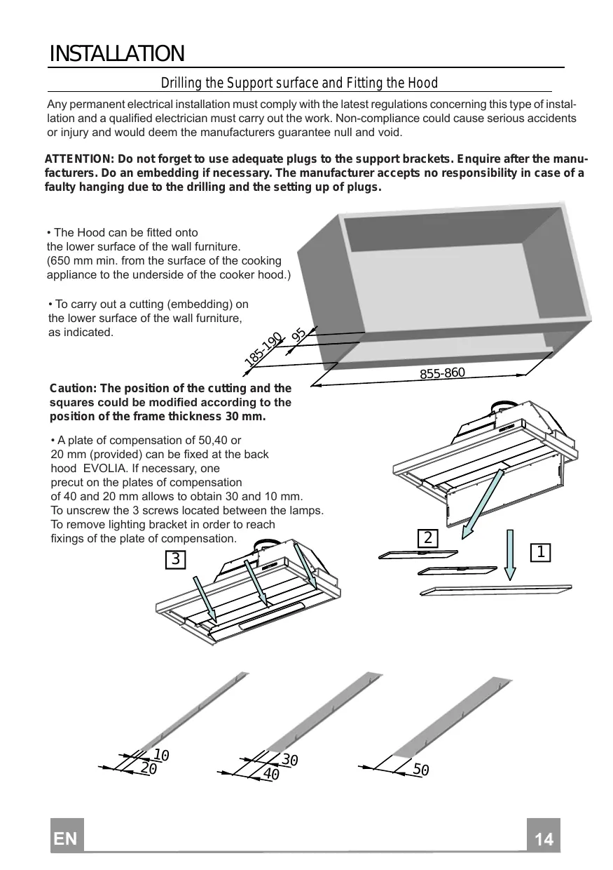
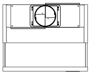
Drilling the Support surface and Fitting the Hood
Any permanent electrical installation must comply with the latest regulations concerning this type of installation and a qualified electrician must carry out the work. Non-compliance could cause serious accidents or injury and would deem the manufacturers guarantee null and void.
ATTENTION: Do not forget to use adequate plugs to the support brackets. Enquire after the manufacturers. Do an embedding if necessary. The manufacturer accepts no responsibility in case of a faulty hanging due to the drilling and the setting up of plugs.
- The Hood can be fitted onto
the lower surface of the wall furniture.
(650 mm min. from the surface of the cooking appliance to the underside of the cooker hood.)
- To carry out a cutting (embedding) on the lower surface of the wall furniture, as indicated.
Caution: The position of the cutting and the squares could be modified according to the position of the frame thickness 30mm
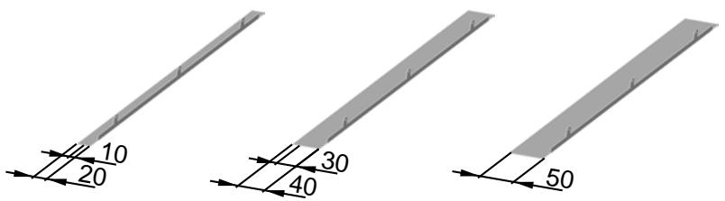
A plate of compensation of 50,40 or
20 mm (provided) can be fixed at the back
hood EVOLIA. If necessary, one
precut on the plates of compensation
of 40 and 20mm allows to obtain 30 and 10mm .
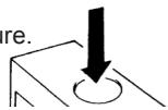
To unscrew the 3 screws located between the lamps.
To remove lighting bracket in order to reach
fixings of the plate of compensation.
- To drill the outlet onto the top of the wall furniture.
- To fix the 2 squares using the provided screws.
Caution: The position of the cutting and the squares could be modified according to the position of the frame thickness 30mm
- To place the anti-backflowflats item 9 over the round outlet. To secure the connections with appropriate clamping rings or adhesive tape.
- DUCTING
- In the extraction mode:
To connect the round outlet of the hood via a rigid or flexible duct of 150mm
- To secure the connections with appropriate clamping rings or adhesive tape not provided.
-
To remove the possible charcoal filte.
-
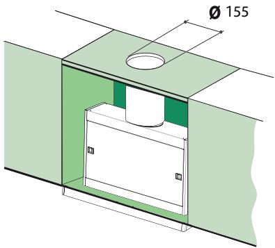
In the recirculation mode:
The filtered air is evacuated in kitchen through an outlet placed on the top of furniture or the hood.
- To drill a hole of 155 mm on the top of furniture.
- To connect the round outlet of the hood via a rigid or flexible duct of 150 mm to the outlet on the to of the furniture.
- To secure the connections with appropriate clamping rings or adhesive tape not provided.
- To fix the charcoal foam onto the metal filters using 2 × 4 barettes.

- The hood can be connected to the mains supply via a double-pole switch having 3mm minimum contact gap on each pole.
- To insert the hood into the cutout and to fix it using the screws provided on squares.
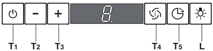
Control panel
| TOUCH CONTROL | FUNCTION | |
| T1 | ON/OFF Motor | Switches the ho od m otor on a nd off. T he la test se lected speed appears on the display. |
| T2 | Speed - | Decreases the suction speed: V3 → V2 → V1 |
| T3 | Speed + | Increases the suction speed: V1 → V2 → V3 |
| T4 | Intensive speed | Activates t he intensive speed from any previously selected speed. The intensive speed can be activated even when the motor is OFF. By pressing the same touch control once again or by switching of f the motor this function can be de activ- vated. Intensive s speed cannot be a c制动 when the delay function is on. Intensive speed has been timed at 10 minutes: H appears on the display and a spot down on the right side flashes once a second. After 10 minutes the system activates automatically the latest selected speed. |
| T5 | Delay | Activates and deactivates the delayed shutdown of the hood (motor +1 lighting) at 30 minutes: the selected speed of the hood appears on t he dis play and a spot down on the right side flashes once a second. By pressing the same touch con- trol once again or by switching off the motor delay function can be deactivated. |
| L | Lighting | Turns light on and off. |
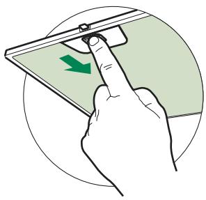
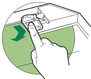
Cleaning the Comfort Panel
- Open the comfort panel; turn the hooks and remove the panel by slightly pressing the rear side.
- Do not wash the comfort panel in the dish washing machine.
- It is recommended to use a neutral detergent liquid and a damp cloth when washing the outer surface of the comfort panel.
- Wash the inner part of the panel as well by using a neutral detergent liquid and a damp cloth; in any case do not use wet sponges or other clothes nor water jet or corrosive detergents.
- Close the sliding panel again and put the comfort panel into its seat.
Grease filters
CLEANING METAL GREASE FILTERS
- The filters must be cleaned every 2 months of operation, or more frequently for particularly heavy usage.
- Open the Comfort Panel by turning the knobs provided.
- Open the panel.
- Remove the filters, one at a time, after disconnecting the relative fastening elements.
- Wash the filters, taking care not to bend them. Allow them to dry before refitting.
- When refitting the filters, make sure that the handle is visible on the outside.
- Close the panel again and hook up the comfort panel.
Odour Iters (Recirculation version)
REPLACING ACTIVATED CHARCOAL FILTERS
- These filters are not washable and cannot be regenerated, and must be replaced approximately every four months of operation, or more frequently with heavy usage.
- Open the Comfort Panel.
- Remove the grease filters.
- Remove the saturated activated carbon filter by releasing the fixing hooks
- Replace the grease filters.
- Close the panel again and hook up the comfort panel.
Lighting
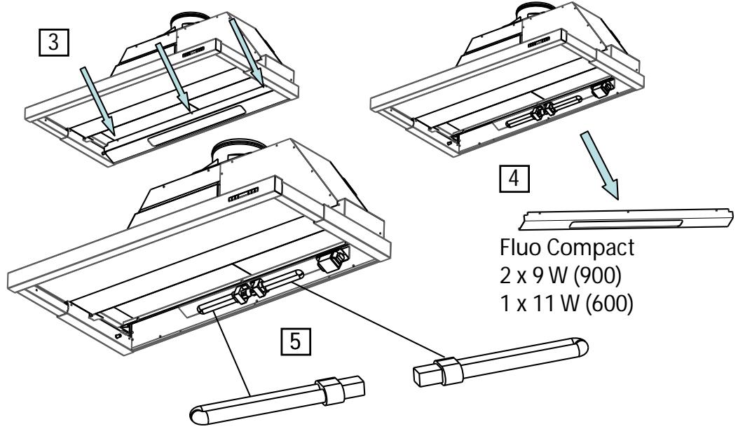
LIGHT REPLACEMENT
- Remove the 3 screws fixing the Lighting support, and pull it out of from the Hood.
- Extract the lamp from the Support.
- Replace with an other of the same type, making sure that the two pins are properly inserted in the lamp holder socket holes.
- Replace the Support, fixing it in place with the two screws removed as above.
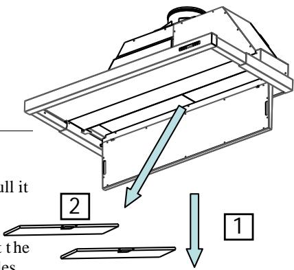
A defective light is cutting off the second one's. In this case, you have to change the two lights.
INSTALLATION
MAJ (UPDATE) :24/03/10
UK ELECTRICAL CONNECTION ELECTRICAL REQUIREMENTS
Any permanent electrical installation must comply with the latest I.E.E. Regulations and local Electricity Board regulations. For your own safety this should be undertaken by a qualified electrician e.g. your local Electricity Board, or a contractor who is on the roll of the National Inspection Council for Electrical Installation Contracting (NICEIC).
ELECTRICAL CONNECTION
Before connecting to the mains supply ensure that the mains voltage corresponds to the voltage on the rating plate inside the cooker hood.
This appliance is fitted with a 2 core mains cable and must be permanently connected to the electricity supply via a double-pole switch having 3mm minimum contact gap on each pole. A Switched Fuse Connection Unit to BS.1363 Part 4, fitted with a 3 Amp fuse, is a recommended mains supply connection accessory to ensure compliance with the Safety Requirements applicable to fixed wiring instructions.
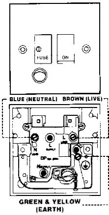
The wires in this mains
lead are coloured in
accordance with the
following code:
Green & Yellow Earth
Blue Neutral
Brown Live
As the colours of the wires in the mains lead of this appliance may not correspond with the coloured markings identifying the terminals in your connection unit, proceed as follows:-
The wire which is coloured blue must be connected to the terminal which is marked with the letter 'N' or coloured black.
The wire which is coloured brown must be connected to the terminal which is marked with the letter 'L' or coloured red.