
MECABLITZ 76 MZ-5 DIGITAL - Studio Flash METZ - Free user manual and instructions
Find the device manual for free MECABLITZ 76 MZ-5 DIGITAL METZ in PDF.

| Product type | Studio flash |
| Brand | Metz |
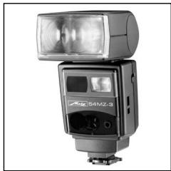
| Model | Mecablitz 76 MZ-5 Digital |
| Guide number (ISO 100/21°) | 76 (meters) / 250 (feet) |
| Lamp head dimensions (W x H x D) | 103 × 244 × 118 mm |
| Control unit dimensions (W x H x D) | 67 × 35 × 89 mm |
| Weight of lamp head (without batteries) | Approx. 880 g |
| Weight of control unit | Approx. 138 g |
| Power supply | NiMH battery pack 76-56 (included) or Power Pack P76 (optional) |
| Number of flashes (full power) | Approx. 160 with battery pack or Power Pack |
| Recycling time (full power) | Approx. 4 sec with battery pack, 3 sec with Power Pack |
| Flash modes | TTL, TTL with preflash, Auto A, Manual M, Stroboscopic |
| Manual partial power | P 1/1 to P 1/256 in 1/3 EV increments |
| Flash duration | Approx. 1/150 sec (full power) to 1/20,000 sec (1/256) |
| Main reflector zoom | 24, 28, 35, 50, 70, 85, 105 mm (24×36) |
| Secondary reflector | Yes, switchable for frontal fill-in with indirect flash |
| Autofocus illuminator | Yes, integrated into the control unit |
| Synchronization | 1st and 2nd curtain, slow (SLOW) |
| Wireless multi-flash | Master/slave with addresses Co1/Co2 and SL1/SL2 (optional SCA 3083) |
| Color temperature | Approx. 5600 K |
| Maintenance and cleaning | Soft, dry cloth; recharge battery regularly; form capacitor every 3 months |
| Safety | Turn off before assembly/disassembly; do not open (high voltage); avoid overheating |
Frequently Asked Questions - MECABLITZ 76 MZ-5 DIGITAL METZ
User questions about MECABLITZ 76 MZ-5 DIGITAL METZ
0 question about this device. Answer the ones you know or ask your own.
Ask a new question about this device
Download the instructions for your Studio Flash in PDF format for free! Find your manual MECABLITZ 76 MZ-5 DIGITAL - METZ and take your electronic device back in hand. On this page are published all the documents necessary for the use of your device. MECABLITZ 76 MZ-5 DIGITAL by METZ.
USER MANUAL MECABLITZ 76 MZ-5 DIGITAL METZ
MECABLITZ 76 MZ-5 digital
Bedienungsanleitung
Gebruiksaanwijzing
Manuale istruzioni
Mode d'emploi
Operating instruction
AbmaBe ca. in mm (B x H x T):
Lampenstab 103× 244× 118
8.7 Commutation metres - pieds (m / ft)
| SCA 3002 - system | ||||||||||
| SCA 300 - system | ||||||||||
| SCA 300 - system | ||||||||||
| SCA 300 - system | ||||||||||
| SCA 300 - system | ||||||||||
| SCA 300 - system | ||||||||||
| STANDARVOET SCA 301 |

- Mecalux-houser 60-26
- SCA-adapter system 300
- SCA-adapter system 3002
Table 1: Guide numbers at maximum light output (P 1/1) 140
Table 2: Flash durations at the individual partial light output levels . . . . 141
Table 3: Camera shutter speeds in stroboscopic mode 142
Foreword
Congratulations on choosing a Metz product and thank you for your confidence in Metz equipment.
It is only natural that you wish to use your flash unit right away. However, it is well worth your while reading these Operating Instructions carefully to ensure you can handle the device without any problems.
Please also open the back cover page with the illustrations.
This flash is suitable for:
- All cameras with a hot shoe and hot shoe flash contact, using a standard centre contact foot 301.
- System cameras.
You can achieve the optimal adjustment to your system camera by using an SCA adapter from the SCA 3002 system (optional extras). This enables digital data transfer can take place between the camera and the flash unit. Optionally, SCA adapters from the SCA 300 system (optional extras) can also be connected to the camera.
The SCA table attached will tell you which adapter you need for your camera. The table also provides information on additional special flash functions.
When using a synch cable or the standard centre contact foot 301 no shutter times shorter than the flash synchronization shutter speed may be set (e.g. 1/125s; see camera operating instructions).
Before mounting or removing the standard centre contact foot 301, a synch cable, a connection cable or an SCA adapter the flash must be turned off at the main switch! When mounting the flash unit on the camera, both devices must be switched off!
1. Safety Instructions
- The flash unit is exclusively intended and approved for photographic use!
- Never fire a flash in the vicinity of flammable gases or liquids (petrol, solvents, etc.) - DANGER OF EXPLOSION!
- Never take flash shots of car, bus or train drivers, or of motorcycle and bicycle riders, whilst they are travelling. They could be blinded by the light and cause an accident!
- Never fire a flash in the immediate vicinity of the eyes! Flash fired directly in front of the eyes of a person or animal can damage the retina and lead to severe visual disorders - even blindness!
- Only use the approved power sources listed in the Operating Instructions!
- Do not expose batteries to excessive heat, sunshine, fire and the like!
- Never throw exhausted batteries on to a fire!
- Exhausted batteries should be immediately removed from the flash unit! Lye leaking out of spent batteries will damage the unit.
- Do not expose the flash unit or battery charger to dripping or splashing water!
- Protect the flash unit from excessive heat and humidity! Do not store the flash unit in the glove compartment of a car!
- Never place material that is impervious to light in front of, or directly on, the reflector screen. The reflector screen must be perfectly clean when a flash is fired. The high energy of the flash light will burn the material or damage the reflector screen if this is not observed.
- Do not touch the reflector screen after a series of flash shots. Danger of burns!
- Never disassemble the flashgun! DANGER: HIGH VOLTAGE!
-
There are no components inside the flashgun that can be repaired by a layperson.
-
When taking a series of flash shots at full light output and fast recycling times as provided by NiMH battery operation, make sure to observe an interval of at least 10 minutes after 20 flashes, otherwise the flash unit will be overloaded.
- Never cover the ventilation slots and intake openings on the flashgun! A built-in cooling fan is automatically switched on when the temperature inside the flashgun exceeds 40^ .
- As a result of the high light energy of a series of flashes shot with full light output in quick succession, the diffuser becomes intensely heated in zoom positions of 35mm and less. In such an event the flash recycling time is automatically extended in order to protect the mecablitz against overheating.
- To remove the control unit's cable, press the gray release button against the cable's plug while pulling out the cable (Fig. 1).
When operated with an SCA adapter from the SCA 3002 system, data exchange must have taken place between the flash unit and the camera before activation of the flash function! For this, simply tap the camera's release button lightly.
- Survey of the flash functions
When using the mecablitz 76MZ-5 digital with an SCA adapter of the SCA 3002 or SCA 300 system, a host of additional flash functions are available. Whether or not they are availabile depends on the specific camera system (camera manufacturer), the special camera type and the SCA adapter. The camera and SCA adapter must support the flash functions! For more detailed information, please refer to the SCA Survey Table and the respective operating instructions of the SCA adapters.
| ● | ● | — | TTL flash mode (standard TTL) |
| ● | — | — | Red-eye pre-flash mode |
| ● | ● | ● | Manual flash exposure correction |
| ●/● | —/● | —/● | Flash bracketing in TTL- / Automatic - flash mode |
| ● | — | — | Canon E-TTL - flash mode |
| ● | — | — | Canon FE-measurement storage |
| ● | ● | — | Nikon matrix controlled fill-in flash |
| ● | — | — | Nikon 3D-multi-sensor fill-in flash |
| ●/● | — | — | Nikon D-TTL / D-TTL-3D flash mode |
| ●/● | — | — | Nikon i-TTL / i-TTL-BL flash mode |
| ● | — | — | Nikon flash exposure measurement storage |
| ●/● | — | — | Minolta ADI measuring / pre-flash - TTL |
| ●/● | — | — | Olympus measuring pre-flash - TTL / Four Thirds -System |
| ● | — | — | Sony measuring pre-flash - TTL |
| ● | ● | ● | Automatic flash mode |
| ● | ● | ● | Manual flash mode with partial light outputs |
| ● | ● | ● | Stroboscopic flash mode |
| ●/● | ●/● | —/● | Cordless Metz remote flash mode for TTL / automatic flash mode |
| ●/● | ●/● | ●/● | Controller / slave - flash mode in the cordless Metz remote flash mode |
| ● | — | — | Slave mode with optical simultaneous firing with SCA 3083 digital |
| ● | — | — | Slave mode with pre-flash measuring suppression with SCA 3083 digital |
| ●/● | —/● | —/● | Automatic / manual aperture setting |
| ●/● | —/● | —/● | Automatic / manual ISO setting |
| ●/● | —/● | —/● | Automatic / manual power zoom control |
| ● | — | — | Extended zoom mode |
| ● | — | — | Exposure shooting format setting |
| ● | — | — | Autofocus measuring beam control |
| ● | ● | — | Flash readiness indicator in camera's viewfinder or camera display |
| ● | ● | — | Correct exposure indication in the camera's viewfinder or camera display |
| ●/● | —/● | —/● | Automatic / manual maximum flash range indication in m or ft |
| ● | ● | — | Automatic flash synch speed control |
| ●/● | ●/● | ●/— | 1st or 2nd curtainisation synchronisation (REAR; 2nd curtain)) |
| ● | ● | — | Triggering control (AUTO-FLASH) |
| ● | ● | — | Slow synchronisation (Slow) |
| ●/● | —/● | — | Pentax contrast control / spot beam mode |
| ● | ● | ● | Modelling light function |
| ● | ● | ● | Acoustic status signals (bleep function) |
| ● | ● | ● | Manual unlocking catch |

3. Preparing the flash unit for use
The control unit (1) of the mecablitz 76 MZ-5 can only be mounted on the camera with the standard foot 301 or with an SCA adapter (optional extras).
As standard the flash unit is equipped with the standard foot 301 for simple flash synchronisation. The shutter speed must be the same as or slower than the flash synch speed of the camera (e.g. 1/125s; see camera operating instructions).
Mounting the standard foot or SCA adapter:
- Switch off the flash unit and camera!
- When using an adapter from the SCA 3002 system, hold the cover plate of the control unit in the middle and clip off.
- Push the SCA adapter or standard foot 301 all the way into the control unit.
Mounting the flash unit:
- Switch off the flash unit and camera!
- Secure the flash bracket with the locking screw to the camera's tripod sock-ket.
- Press the unlocking button ⑤ of the battery pack and turn the battery lid ⑥ anti-clockwise until the first locking position is reached.
- Insert the holding block ⑦ of the bracket in the guiding groove of the flash unit.
- Secure the holding block ⑦ with the clamping screw.
- Turn back the battery lid ⑥ clockwise until it is locked in again - the rectangular catch will then cover the opening of the guiding groove.
- Insert the control unit ① with mounted SCA adapter or standard foot 301 in the camera's accessory shoe and secure with the clamping nut.
- Insert the control unit's cable plug into the handle-mount flash unit.
Dismantling the standard foot or SCA -adapter:
-
Turn off the flash unit and camera!
-
To pull off the control unit's cable press the unlocking button on the handle mount flash unit against the cable plug and simultaneously disconnect the cable (Fig. 1).
- Press the locking catch against the control unit (Fig. 2).
- Withdraw the standard foot 301 or the SCA adapter (Fig. 2).
4. Power supply
The flash unit can be operated as required with:
- Metz NiMH battery pack 76-56 (included)
- Power Pack P76 (optional extra)
Never cover or seal the ventilation slots and intake openings on the on the reflector head!
4.1 Operation with NiMH battery pack 76-56
Prior to its first use the battery pack must be charged. The battery pack can only be charged outside the flash unit. The battery charger for the battery pack is included.
The battery warning light only comes on when the battery pack is being used. The operating light in the handle starts flashing when the battery is exhausted, and the battery warning light on the display becomes illuminated.
Replacing and charging the battery
- Switch off the flash unit and camera!
- Press the unlocking catch ⑤ on the battery pack, turn the battery cover by approx. 45^ anti-clockwise until it become audiably disengaged at the 2nd lock-in position and remove (Fig. 3).
- Connect the charger 970 to the charging socket of the battery pack and then plug into the mains.
The charging time with a completely empty battery pack is approx.
2.5 hours. If the battery pack is only partially discharged, the charging time will be correspondingly shortened.
The battery charger operates in a voltage range of 100V ... 240 V. The
charging process is monitored by a micro-controller in the charger. When the battery pack has been completely charged, the charging process is automatically terminated and the charger switches over to trickle charging.
Only charge the battery pack with the original Metz battery charger!
- Turn the battery cover anti-clockwise until the 2nd lock-in position is reached before the battery is returned to the handle.
- For insertion the battery's charging socket must be inside the extension of the aluminium rail of the handle.
- After insertion, turn the battery cover clockwise until the stop point is reached. To identify an exhausted battery:
Turn the battery cover clockwise until the stop point is reached.
To identify a newly charged battery:
Turn the battery cover anti-clockwise until the stop point is reached.
4.2 Operation with power pack P76
If the number of flashes and flash recycling times are insufficient for your application, the flash unit can be powered by a Power Pack P76 (optional extras). The power pack is connected to the flash unit with a connecting cable V76 (optional extras). No battery pack needs to be installed in the flash unit at the same time.
A battery installed in the flash unit may stay there.
Before connecting the power pack or the connecting cable V76 to the flash unit, the main switch 19 of the flash unit must be pushed to the bottom position (AUS or OFF).
The flash unit can then be turned on and off with the switch on the power pack (see the operating instructions of the power pack).
In order to protect the flash unit against thermal overloading while operating with a power pack, the flash recycling times are correspondingly lengthened in the case of extreme demands by a monitoring system!
Before connecting and removing the connecting cable or power pack, switch off all devices affected!
5. Controls and displays
- The flash readiness indicator lights ⑧ ⑥ up when the flash capacitor is charged and the flash unit can be triggered. When operated with an SCA adapter the camera - as far as is necessary - is automatically switched to flash synch time. The flash readiness indicator is visible on the handle and control device.
- With the manual firing button ⑧ 16 a flash can be triggered if flash readiness is available. In the TTL and in manual flash modes this triggers a flash with full light output. In automatic flash mode or with manual partial light outputs, a flash is triggered according to the parameters set (ISO / aperture / partial light output). The handle and control unit both have manual firing buttons. In the flash mode of the handle mount without control unit, an addressing flash is fired for the cordless Metz remote system (see 17).
- The flash readiness indicator ⑨ lights up for approx. 3 seconds if the film has been correctly exposed in TTL or automatic flash mode. When operating with an SCA adapter a corresponding signal occurs, depending on the type of camera, in the camera's viewfinder or in the camera display. In addition, the flash readiness signal appears on the control unit.
5.1 Controls and displays on the flash handle mount
- To turn on the flash unit push the main switch ⑲ to the ON position. If the flash unit is ready, the flash readiness indicator will light up ⑧ ⑮. In the bottom position of the main switch the flash unit is turned off.
- With the switch for the second reflector ④ the second reflector ② can be connected, e.g. for frontal fill-in light when the flash is bounced. For this, push the switch ④ to the top position. If the amount of light is too great, it can be reduced in the intermediate position of the switch ④ by 1/2 or 1/4. If the second reflector is switched on, the symbol appears in the display. In the bottom switch position, the second reflector is switched off.
Use of the second reflector generally only makes sense if the main reflector is swivelled, i.e. in bounce flash photography. If the main reflector is not swivelled, the second reflector will not be activated and the symbol not shown!
The sub-modes stroboscope and Metz remote are not supported by the second reflector.
- With the ML button ⑤ a modelling light (ML) can be triggered if the flash is ready. A modelling light is a high frequency stroboscopic flashlight. For a duration of approx. 4 seconds the impression of quasi-permanent light is created. With the modelling light the light distribution and shadow formation can be judged before a photo is taken. Press the ML button ⑤ for approx. 2 seconds to trigger the modelling light. In the cordless Metz remote system the triggering of the modelling light on the controller also triggers the modelling light of all the slave flash units that are equipped with a modelling light function.
- With the switch LOCK ⑱ the buttons of the control unit can be locked against unintentional incorrect settings.
Push the button ⑱ to the top position (LOCK) to lock the controls. The symbol O-m appears in the display.
To unlock the controls push the button ⑱ to the bottom position.
The manual firing button on the handle mount ⑧ ⑥ and control unit as well as the ML button ⑤ are not affected by the lock!
5.2 Controls and displays on the control unit
The four buttons of the control unit are endowed with different functions. The particular function allocated is in each case shown directly above the button in the display of the control unit.
Upon first pressing the button the display lighting is initially activated for approx. 10 sec. With every further press of the button the illumination time is extended and the corresponding function is chosen or activated.
The flash mode is selected by means of the button controls (TTL, automatic A, manual M, Stroboscopic, etc). Depending on the flash mode various flash parameters (e.g. aperture, zoom position of the reflector, flash exposure correction value, partial light output, ISO value, stroboscopic frequency, etc) or additional special functions can be set.
Button explanation:
Button "Mode" Call the menu and set the flash mode (Mode menu).
Button „Para" Call the flash parameters and change settings, e.g. aperture, ISO etc (Parameter menu).
Button „SEL“ Call special functions and set (Select menu).
Button "Set" Set button to confirm the choice of a special function.
Button Manual firing button 18. Trigger test flash.
Button Return button to confirm settings.
Buttons UP /DOWN - buttons to move inside a menu.
Buttons + - PLUS / MINUS - buttons to change the setting values.
In the display of the control unit the following parameters can be shown:
Flash mode, flash parameters, maximum flash range and activated special functions. The current display extent in each case depends on the flash mode selected, the type of camera and the SCA adapter or standard foot 301.
6. Flash modes (Mode - menu)
The flash unit supports the flash modes TTL, automatic A, manual M und stro-boscopic
When operating the flash unit with an SCA adapter from the SCA 3002 system additional flash modes may be supported, depending on the camera system (manufacturer) and camera type. These can be selected or activated in the mode menu.
Setting procedure
- Press the "Mode" (flash mode) button repeatedly until "Mode" appears in the display.
- Set the flash mode required (TTL, automatic A, manual M, etc) with the buttons UP and DOWN . The flash mode selected is highlighted with a bar. The setting is immediately active.
- Press the button "Return" . The display returns to its normal appearance.
ce. If the button "Return" is not pressed, the display automatically returns to its normal appearance after approx. 5 seconds.
All flash modes, except remote, are also supported by the second reflector of the flash unit.
Flash mode with standard foot 301 or SCA adapter from the SCA 300 system
The flash parameters for ISO, aperture and focal length of the lens or reflector position must be set manually on the control unit of the flash unit (see 7). The maximum flash range indication in the display of the control unit depends on the flash parameters set.
Flash mode with SCA adapter from the SCA 3002 system
The flash parameters for ISO, aperture and focal length of the lens or reflector position are set automatically when the camera transmits the corresponding data to the flash unit (see operating instructions of camera and SCA adapter).
The maximum flash range indication in the display of the control unit is made in accord with the flash parameters transmitted by the camera.
If the camera does not transmit one or several flash parameters, these must be set manually on the control unit (see 7).
6.1 TTL flash mode
The TTL flash mode is only possible if the camera and SCA adapter support the TTL flash mode (see operating instructions of camera and SCA adapter)!
In the TTL flash mode a sensor in the camera measures the light reflected by the subject through the lens (TTL = through the lens). By these means during the light measurement, for example, filter attachments in front of the lens and the exact picture segment are taken into account. Where the quantity of light is sufficient, the automatic exposure system of the camera switches off the flash light via the SCA adapter.
The maximum flash range can be read on the display. The shortest shooting distance is approx. 10% of the maximum flash range. The subject should be
approximately in the centre third of the maximum flash range shown, so that the automatic exposure system has enough room for equalisation.
For the functioning of the TTL mode the ISO and aperture settings are irrelevant! If the aperture and ISO values are correctly set, the correct maximum flash range will be shown in the display.
Setting procedure see cap. 6.
6.2 TTL flash mode with measuring pre-flash
The TTL flash mode with measuring pre-flash is a further development of the standard TTL flash mode. Here the reflective qualities of the subject are determined shortly before the actual shot with one or several measuring pre-flashes and evaluated by the camera electronically. In addition, distance data from the AF system of the camera can be taken into account. The light regulation occurs through the automatic exposure system of the camera via an adapter from the SCA 3002 system.
The various technologies of the TTL flash mode with measuring pre-flash vary, depending on the camera system (manufacturer) and camera type.
The various possible flash modes are in addition shown in the menu "Mode" and can be activated there.
Example:
| Camera system | Flash technology | Display |
| Canon with SCA 3102 | E-TTL | E TL |
| Olympus with SCA 3202 | Pre-flash TTL | TL |
| Konica-Minolta with SCA 3302 | ADI-measuring / TTL pre-flash | TL |
| Nikon with SCA 3402 | i-TTL | 4 TL |
| i-TTL-BL | 4 TL BL | |
| D-TTL | 4 TL | |
| D-TTL-3D | 4 TL BL | |
| 3D-multi-sensor fill-in flash | $4 TL BL |
Many digital cameras support only the TTL flash mode with measuring
pre-flash (e.g.. Canon E-TTL, Minolta ADI, Nikon D-TTL, Nikon iTTL etc). The standard TTL flash mode is not supported by these cameras. For more details, see operating instructions of camera and SCA adapter.
Setting procedure see cap. 6.
6.3 Automatic flash mode
In the auto flash mode A, a sensor ⑩ in the control unit of the flash unit measures the light reflected off the subject. The sensor ⑩ has a range of approx. 25^ , and only measures during its own light emission. If the amount of light is sufficient, the automatic exposure system of the flash unit switches the flash off. The sensor must be directed towards the subject.
The maximum flash range is shown on the display. The shortest shooting distance is approx. 10% of the maximum flash range. The subject should be approximately in the centre third of the maximum flash range shown, so that the automatic exposure system has enough room for equalisation.
Some cameras will not support the auto flash mode A when the flash unit is equipped with an adapter from the SCA 3002 system. In this event the use the standard foot 301.
Setting procedure see cap. 6.
6.4 Manual flash mode M
In the manual flash mode M, the flash unit will emit the full light energy if partial light output has not been set. Adaptation to the given photographic situation can e.g. be achieved by setting the corresponding aperture on the camera or by selecting a suitable partial light output level
The display indicates the flash-to-subject distance for correct flash exposure.
Some cameras will not support the manual mode M when the flash unit is equipped with an adapter from the SCA 3002 system. In this event the use the standard foot 301.
Setting procedure see cap. 6.
6.5 Stroboscopic mode
The stroboscopic flash mode is a manual flash mode. When using it several
flash exposures can be used on one shot. This is particularly interesting for motion studies and special effects (Fig. 7). In stroboscopic mode, a predetermined number of flashes are fired at a certain flash frequency. Consequently, only a partial light output is available with a maximum of ? power.
For stroboscopic exposures, you can select a flash frequency (flashes per second) of 1...50 Hz in 1 Hz increments, and a number of flashes between 2 ... 50 in single increments (see 7).
The maximum possible partial light output level in stroboscopic mode is automatically adjusted. It depends on the ISO and aperture values. To achieve short flash durations, the partial light output level can be adjusted manually to a minimal value of 1/256.
The display indicates the correct distance for the parameters set. You can adjust the distance displayed to the distance to the subject by varying the aperture value or the partial light output.
No aperture and ISO values are shown in the display in stroboscopic mode! The stroboscopic mode cannot be used when the secondary reflector is switched on.
Setting procedure see cap. 6.
7. Flash parameters (Parameters menu)
In order for the flash unit to function properly, it is necessary that you adjust various parameters, such as the zoom position of the flash reflector, aperture, light sensitivity ISO etc, to the settings of the camera.
The flash parameters must be set manually when the flash is operated with the standard foot 301 or an SCA adapter from the SCA 300 system.
When operating the flash unit with an SCA adapter from the SCA 3002 system the flash parameters are set automatically if the camera sends the corresponding data to the flash unit (see operating instructions of camera and SCA adapter). For the purposes of the automatic data transmission, the combination of camera, flash unit and SCA adapter must be mounted and switched on. In addition, an exchange of data must occur between camera and flash unit. It is enough simply to tap the camera release lightly.
The maximum flash range appears in the display according to the flash parameters set.
Setting procedure
- Press the "Para" (Parameter) button repeatedly until the flash parameters required (see below) are shown in the display.
- Set the value required with the PLUS / MINUS buttons. The setting will take effect immediately.
- Press the button "Return". The display automatically switches back to its normal appearance. If the button "Return" is not pressed, the display switches back to its normal appearance after approx. 5 sec.
When the flash parameters are set automatically with an SCA adapter from the SCA 3002 system various parameters (e.g. aperture and ISO) cannot be altered manually!
7.1 Aperture (F)
If no digital data transmission takes place between camera and flash unit (e.g. when using an adapter from the SCA 300 system or the standard foot 301), the aperture values (F) from 1.0 to 45 (at ISO 100) can be set manually in increments of complete aperture levels.
For the auto flash mode A and manual flash mode M the camera and flash unit must be set to the same aperture value.
For the TTL flash mode, the setting of the aperture value is necessary only for the correct maximum flash range indication, but not for the function!
In the event of digital data transmission between camera and flash unit, intermediate values can also be set automatically.
Depending on the camera type and SCA adapter (SCA 3002 system), the aperture value will not be shown in the display!
Setting procedure see cap. 7.
7.2 Reflector position (Zoom)
If no digital data transfer takes place between camera and flash unit (e.g. when using an adapter from the SCA 300 system or standard foot 301), the
reflector positions can be set as
24 mm - 28 mm - 35 mm - 50 mm - 70 mm - 85 mm - 105 mm (35 mm format 24 x 36) M-Zoom appears in the display.
In the case of digital data transmission between the camera and flash unit, the reflector positions can be set automatically. A-Zoom appears in the display.
Setting procedure see cap. 7.
7.3 Flash exposure correction (EV)
In the event of strong contrast differences between subject and picture baskground, manual flash exposure correction (EV) may be necessary.
Correction factors from -3 EV to + 3 EV (f-stops) can be set in one-third increments (see too 10).
Setting procedure see cap. 7.
7.4 Light sensitivity (ISO)
If no digital data transmission takes place between camera and flash unit, (e.g. when using an adapter from the SCA 300 system or the standard foot 301), the ISO values for the light sensitivity can be set manually from 6 to 6400.
For the automatic flash mode A and manual flash mode M the camera and flash unit must be set to the same ISO value.
For the TTL flash mode the setting of the ISO value on the flash unit is only necessary for the correct maximum flash indication, but not for the function!
Depending on the camera type and SCA adapter (SCA 3002 system), the ISO value will not be shown in the display!
Setting procedure see cap. 7.
7.5 Manual partial light output (P)
In the manual flash mode M and stroboscopic mode i t the light output can be adapted to the shooting situation through setting a manual partial light output (P).
The setting range extends in the manual flash mode M from P 1/1 (full light output) to P1/256 in one-third increments. In stroboscopic flash mode the maximum adjustable partial light output can be adjusted to the flash parameters.
In stroboscopic flash mode the reduction of the manual partial light output is only possible in complete steps!
Setting procedure see cap. 7.
7.6 Stroboscopic flash number (N)
In stroboscopic flash mode the flash number (N) per shutter release can be set. The number of flashes can be set from 1 to 50 in single increments. The maximum possible manual partial light output is adjusted automatically at the same time.
Setting procedure see cap. 7.
7.7 Stroboscopic flash frequency (f)
In the stroboscopic flash mode the flash frequency (f) can be selected. The flash frequency indicates the number of flashes per second.
The flash frequency can be selected from 1 to 50 in single increments. The maximum possible manual partial light output is adjusted automatically at the same time.
Setting procedure see cap. 7.
- Special function (Select menu)
The special functions are selected with the button "Sel" (Select). Depending on the camera system (manufacturer), camera type and SCA adapter, various special functions can be selected.
Setting procedure
- Press the button "SEL" repeatedly until "Select" appears in the display.
- Select the menu point or special function required with the Up / Down buttons . The menu point selected will be highlighted with a dark bar.
-
Press the button "Set" and so confirm the choice of the special function.
-
Enter the required setting with the Up / Down buttons . The setting takes effect immediately.
- Press the button "Return" repeatedly until the normal display is shown. If the button "Return" is not pressed, the display will automatically return to its normal appearance after approx. 5 seconds.
8.1 Bleep function (bleep)
With the bleep function the user can have some device functions of the flash unit conveyed acoustically. In this way the photographer can concentrate fully on the subject and shot and need not pay attention to additional optical status displays!
The bleep function acoustically indicates when the flash is ready, the correct flash exposure or an incorrect setting.
Acoustic signal after the flash unit is switched on:
- A short (approx. 2 second) uninterrupted bleep signal after switching on indicates the flash readiness of the flash unit.
Bleep signal after shooting:
- A short (approx. 2 second) uninterrupted bleep signal immediately after the shot indicates that the latter was correctly exposed and that flash readiness remains available. If no bleep signal immediately follows the shot, the photograph was under-exposed.
- An intermittent bleep signal immediately after the shooting is the signal for a correctly exposed flash light shot. The flash readiness continues, but only after a subsequent (approx. 2 second) continuous tone (bleep).
Bleep signals in the automatic flash mode:
- A short bleep as an acoustic alarm is generated in the auto flash mode if the aperture and ISO setting would exceed the permissible light control range. The auto aperture is automatically adjusted to the next permissible value.
With the bleep function switched on the symbol is additionally shown in the display.
Setting procedure see cap. 8.
8.2 Flash bracketing (FB)
A series of flash exposures (flash bracketing FB) can be carried out in the flash modes TTL and auto A flash modes. A flash bracketing series consists of three successive flash shots with different flash exposure correction values.
When setting a flash bracketing series, FB and the correction value are shown in the display. The possible correction values range from 1/3 to 3 apertures in one-third aperture increments.
With the display "FB 0" the flash bracketing series is deactivated.
- The first shot is taken without a correction value. In the display, "FB1" is shown in addition.
- The second shot is taken with a minus correction. In the display, "FB2" and the minus correction value (EV) are shown in addition.
- The third shot is taken with a plus correction. In the display, "FB3" and the plus correction value (EV) are shown in addition.
- After the third shot the flash bracketing series is automatically deleted. The "FB" in the display disappears.
Flash bracketing in TTL flash mode
A flash bracketing series in TTL flash mode is only possible if the flash unit is fitted with a suitable adapter from the SCA 3002 system and the camera supports the setting of a manual flash exposure correction on the flash unit (see operating instructions of the camera and SCA adapter)! Otherwise the shots are taken without correction value!
Flash bracketing mode in automatic flash mode A
For a flash bracketing series in automatic flash mode A, it is sufficient if the flash unit is equipped with the standard foot 301.
With some camera types the auto flash mode A is not possible for technical reasons, if the flash unit is equipped with an adapter of the SCA 3002 system (see operating instructions of the camera and SCA adapter)! In this case use the standard foot 301 in place of the SCA adapter!
Setting procedure see cap. 8.
8.3 Synchronisation on the 2nd curtain (REAR)
With normal synchronisation the flash unit is triggered at the beginning of the shutter interval (synchronisation on the 1st curtain). This is the standard mode and is performed by all cameras.
When operating with an SCA adapter many cameras support synchronisation on the 2nd curtain (REAR, 2nd curtain). Here the flash unit is triggered at the end of the shutter interval. In the case of long shutter intervals (>1/30s) and moving light sources, this creates a "more natural" impression of the shooting situation. The light traces then streak in the shot behind the light source. The setting is made either on the camera or on the flash unit. For more details, see the operating instructions of the camera and SCA adapter.
- When set to "REAR ON", the synchronisation occurs on the 2nd curtain.
- When set to "REAR OFF", the normal synchronisation is set.
The REAR function can only be selected and set when operating a suitable camera and an SCA adapter from the SCA 3002 system (see operating instructions of the camera and SCA adapter)!
Setting procedure see cap. 8.
8.4 Extended zoom mode (zoom ext)
The extended zoom mode reduces the focal length of the reflector by one increment as compared to the focal length of the camera lens. This results in a wider illumination and additional diffused light (reflections) in rooms, which, in turn, produces a softer flash illumination.
Example:
The focal length of the camera lens is 50~mm . In extended zoom mode the flash unit adjusts the reflector position to 35~mm . In the display 50~mm continues to be shown.
- "Ext ON" in the display indicates that the extended zoom mode is activated.
- "Ext OFF" in the display indicates that the extended zoom mode is deactivated.
For system reasons the extended zoom mode is supported for a focal length of lens from 28 mm. The flash unit must be equipped with a suitable SCA adapter from the SCA 3002 system and the camera must supply the data for the focal length of the lens to the flash unit.
After the activation of the extended zoom mode, E-Zoom appears in the display next to the focal length.
Setting procedure see cap. 8.
8.5 Shooting format adjustment (zoom size)
When operating a digital camera with a suitable SCA adapter from the SCA 3002 system the display for the reflector position can be adjusted to the chip format (dimensions of the picture recording component).
- "Size ON" in the display indicates that the shooting format adjustment is activated.
- "Size OFF" in the display indicates that the shooting adjustment is deactivated.
After the activation of shooting format adjustment, S-Zoom appears in the display next to the focal length.
For more details, see the operating instructions of the camera and SCA adapter.
Setting procedure see cap. 8.
8.6 Remote mode (remote)
With this special function the flash unit can be activated as controller or slave in the cordless Metz remote mode. Here the following settings are possible:
Remote OFF
- Remote Co1; the flash unit functions as controller with address 1.
- Remote Co2; the flash unit functions as controller with address 2.
When the controller mode is activated the symbol Co. flashes beneath the display for flash mode.
When operating the control unit with the slave adapter SCA 3083 digital,
the following settings are possible:
- Remote SL1; the flash unit functions as slave with address 1.
- Remote SI2; the slave functions as slave with address 2.
When the slave mode is activated, the symbol SL flashes under the display for the flash mode.
For the slave mode the flash unit must be switched to the flash mode TTL (see 6)!
For more details on the cordless Metz remote mode see chapter 17.
Setting procedure see cap. 8.
8.7 Metre - feet commutation (m / ft)
The maximum flash range in the display of the flash unit can be optionally set in metres m or feet ft. The setting is made under the menu point m / ft.
Setting procedure see cap. 8.
9. Zoom position of the flash reflector
The adjustment of the zoom position of the flash reflector ① can be made for a focal length of lens from 24mm (24 x 36). For lenses with focal lengths from 20mm a wide angle diffuser (included) can be used.
The following zoom positions are available:
24 mm - 28 mm - 35 mm - 50 mm - 70 mm - 85 mm - 105 mm (corresponding to 24 x 36)
When using the wide angle diffuser the zoom reflector must be in the 24 mm position!
Automatic zoom adjustment
If the flash unit is equipped with an SCA adapter from the SCA 3002 system and is operated with a camera, which reports the data for the focal length of the camera to the flash unit, the zoom position of its reflector automatically adjusts to the focal length of the lens. In the display of the flash unit, A-Zoom and the reflector position (mm) are shown.
Manual zoom adjustment
If the flash unit is used with an SCA adapter from the SCA 300 system, a standard foot 301 or a camera unable to transmit the focal length data, the zoom position of the flash reflector must be set by hand. In this case, M-Zoom appears in the display.
If you use a zoom lens and do not always require the full guide numbers and range of the flash unit, you can leave the position of the zoom reflector at the beginning focal length of the zoom lens. This will guarantee that your picture is always completely illuminated. In this way you can spare yourself the continuous adjustment of the focal length of the lens.
Example:
You use a zoom lens with a focal length range of 35mm to 105mm . In this example you set the position of the zoom reflector to 35mm !
Manual adjustment of the zoom position in A zoom
The zoom position of the reflector can also be changed when operating the flash unit with an adapter from the SCA 3002 system and a camera that transmits data in order e.g. to achieve particular lighting effects (e.g. hot spot etc):
After saving, M-Zoom appears in the display.
Returning to A-Zoom mode
- Tap the camera release lightly so that data exchange can take place between the flash unit and the camera.
- Change the zoom position repeatedly until A-Zoom appears in the display.
10. Manual flash exposure correction
The automatic exposure system of the mecablitz and most cameras is based on a subject reflection factor of 25% (average reflection of subjects shot with flash). A dark background that absorbs a great deal of light, or a highly reflective bright background (e.g. when shooting against the light), can result in overexposure or underexposure.
To compensate for the aforementioned effect, the exposure can be manually corrected with a correction value adapted to the given photographic situation. This correction value depends on the contrast between subject and background!
In the TTL and A mode of the flash unit, manual flash exposure correction factors of -3 EV to +3 EV (f-stops) can be set in one-third increments.
Many cameras have a setting element for exposure corrections which can also be used in the TTL flash mode. Please refer to the explanations in the operating instructions for the given camera and the SCA adapter.
Dark subject in front of a bright background:
Positive correction value (approx. 1 to 2 f-stops EV).
Bright subject in front of a dark background:
Negative correction value (approx. -1 to -2 f-stops EV).
Entering a correction value may result in a change of the maximum flash range indicated on the display of the flash unit and its adaptation to the correction value (depending upon the camera type and SCA adapter)!
A manual flash exposure correction in TTL flash mode can only be made if the camera and the SCA adapter (only SCA 3002 system) support this function (see operating instructions of camera and SCA adapter)! If the camera or the SCA adapter do not support this function, the correction value set will remain ineffective.
The manual flash exposure correction value must be set in various camera types. No correction value is then shown in the display of the flash unit.
11. Fill-in flashes
11.1 Automatic TTL fill-in flashes
Most cameras automatically activate fill-in flash when in full mode, programme auto mode "P" and in the image control modes during daylight (see camera operations instructions).
With the fill-in flash you can eliminate annoying shadows and in centre-jour shots achieve a well-balanced illumination of subject and background. A computer-controlled measuring system in the camera provides for the appropriate combination of shutter speed, working aperture and flash output. A setting or display for the automatic TTL fill-in flash mode does not occur on the flash unit.
Ensure that backlight does not shine directly into the lens. This would deceive the camera's TTL measuring system!
11.2 System-specific TTL fill-in flashes
Depending on the camera system (manufacturer), some camera types have system-specific TTL fill-in flashes. These are activated either on the camera itself or on the flash unit (see operating instructions of camera and SCA adapter).
The activation on the flash unit is carried out in the menu "Mode" and is only possible if the camera and the SCA adapter support the fill-in flash control involved!
NIKON
Various Nikon cameras together with the SCA 3402 adapter and the mecablitz 76 MZ-5 support the matrix-controlled TTL fill-in flash mode TL BL or 3D-multi-sensor fill-in flash mode BL.
Please note that depending on the camera, certain fill-in flash controls cannot be activated if "SPOT measuring" (exposure control) is activated on the camera or if, when selecting SPOT measuring, the corresponding fill-in control is automatically deactivated!
11.3 Auto fill-in flash
When using auto fill-in flashes, a correction value of approx. -1 EV ... -2 EV for the flash exposure is set on the flash unit in the auto flash mode A (see 7.3). This creates a naturally balanced fill-in effect for the shadow sections during the shooting.
12. Bounce flash
The use of bounce flash provides for a softer illumination of the subject and reduces harsh shadow formation. In addition, the physically determined drop in light from the foreground to the background is reduced.
For bounce flash the main reflector ① of the flash unit can be swivelled horizontally and vertically. The reflection surfaces should be colour-neutral or white to avoid colour tinges during the shooting. For frontal fill-in light the second reflector ② can be activated with the switch ④ in addition (see 5.1).
When swivelling the reflector vertically, care should be taken to move it through a sufficiently wide angle to prevent any direct light from the reflector falling on the subject. For this reason, swivel it to a finishing position of at least 60^ .
With the zoom reflector swivelled there is no maximum flash range indication in the display.
13. Flash synchronisation
13.1 Normal synchronisation
During normal synchronisation the flash unit is triggered at the beginning of the shutter interval (synchronisation on the 1st curtain). This is the standard mode and is performed by all cameras. No setting is necessary.
13.2 Synchronisation on the 2nd curtain
When operating with an SCA adapter many cameras support synchronisation on the 2nd curtain (Rear, 2nd curtain). Here the flash unit is only triggered at the end of the shutter interval. This creates a "more natural" reproduction of the shooting situation during long shutter intervals (>1/30s) and with moving sources of light. The light traces then streak back in the shot to the light source. The setting is made either on the camera or on the flash unit (see 8.3).
For more details see the operating instructions of the camera and SCA adapter.
13.3 Slow synchronisation
When the flash unit is operated with an SCA adapter it is possible with many cameras to select slow synchronisation (SLOW). Here the camera sets shutter intervals that are adapted to the surrounding light. During darkness this helps to emphasise the picture background. The setting is made on the camera. For more details, see the operating instructions of the camera and SCA adapter.
14. Maximum range display
The range display can as required be made in metres (m) or feet (ft) - see 8.7.
If the reflector is swivelled, and in Metz remote mode, no maximum range display is shown!
14.1 Automatic adjustment of the working range display
Various cameras transmit the flash parameters for light sensitivity ISO, focal length of the lens (mm), aperture and exposure correction to the flash unit. The flash unit then adapts its settings automatically. The maximum flash range is calculated and shown in the display on the basis of the flash parameters and the guide numbers.
For an automatic adjustment of the maximum flash range indication the flash unit must be equipped with an SCA adapter of the SCA 3002 system. In addition, the camera must transmit the flash parameters required to the flash unit (on this see the operating instructions of the SCA adapter and camera)! An exchange of data must take place between the camera and flash unit (e.g. by lightly tapping the camera release button)!
14.2 Manual adjustment of the maximum range display
If the flash unit is used with an SCA adapter from the SCA 300 system or the standard foot 301 or a camera that does not transmit the flash parameters, the flash parameter(s) for zoom position, light sensitivity ISO and aperture value must be set manually for a reliable maximum flash range indication.
14.3 Maximum range displays in TTL and automatic flash mode
The value for the maximum range of the flash is shown in the display of the flash unit. The value shown refers to a subject reflection factor of 25% of the subject, which applies to most shooting situations. Wide deviations of the subject reflection factor, e.g. in the case of highly or poorly reflective objects, can influence the maximum flash range.
While shooting, it is important to pay attention to the maximum flash range indication in the display of the flash unit. The subject should be in the centre third of the value shown. This provides the automatic exposure system with enough room for manoeuvre for equalisation. The minimum distance to the subject should not be less than 10% of the value shown in order to avoid over-exposure! The adjustment to the particular shooting situation can be achieved by changing the aperture on the lens.
14.4 Maximum range display in manual flash mode M
The distance value is shown in the display of the flash unit, which must be maintained for a correct flash exposure. The adjustment to the specific shooting situation can be achieved by changing the aperture on the lens and by choosing between full light output and a partial light output "P".
14.5 Cancelling the maximum range display
If the reflector head is swivelled from its normal position or the flash unit is working in Metz remote mode, no distance indication appears in the display!
15. Pre-flash function against "red-eye effect"
The "red-eye effect" occurs when the people to be photographed look more or less directly into the camera, the ambient light is dark and the flash unit is located close to the camera. The flash unit then lights up the background of the eye through the pupil.
One or several pre-flashes lead to the pupils of the subject closing further and hence reducing the red-eye effect. The function is set on the camera (see operating instructions of camera and SCA adapter).
16. Autofocus measuring beam
When operating the flash unit with an SCA adapter from the SCA 3002 system, depending on the camera type, the AF measuring beam in the control unit is activated. A striped pattern is projected on to the subject, on which the AF system of the camera focuses. The maximum range depends on the f-number of the lens. With a standard lens the range varies from 0.7m to approx. 6m .... 9m (for more details see the operating instructions of the camera and SCA adapter).
The AF measuring beam only supports the central AF sensor of the camera. If a decentral AF sensor of the camera is chosen manually or automatically, the AF measuring beam may not be activated, depending on the camera type!
Most cameras support the AF measuring beam only in the mode "Single AF"!
17. Metz remote mode
Remote mode is the cordless remote control of additional flash units. In this mode, the external flash unit on the camera manages, as a controller, the additional flash units as slaves in such a way that the automatic exposure control of the controller extends to all the slave flash units.
The remote mode works with weak flash pulses. For this reason the ambient light should be as low as possible. The working area depends on the subject and ambient light and comprises roughly 5 metres.
The Metz remote mode is supported by various flash unit types:
| Mecablitz type | Controller functionn | Slave function |
| 76 MZ-5 digital | yes | yes |
| 70 MZ-5 | yes | yes |
| 70 MZ-4 | yes | yes, with SCA 3083 |
| 54 MZ-… | yes | yes, with SCA 3083 |
| 50 MZ-5 | yes | ja |
| 45 CL-4 digital | no | yes, with SCA 3083 |
| 44 MZ-2 | no | yes, with SCA 3083 |
| 40 MZ-… | yes | yes, with SCA 3083 |
| 34 CS-… | no | yes |
| 28 CS-2 digital | no | yes |
The flash units mecablitz 76 MZ-5 digital, 70 MZ-5 and 50 MZ-5 automatically become slave flash units if the handle mount is operated without a control unit.
If the handle mount of these units is operated with a control unit, then the control unit must be equipped with the SCA adapter SCA 3083 (optional extras) for the slave flash mode!
Please note that the sensor ④ for the cordless Metz remote mode in the slave flash unit must be able to receive the light of the controller!
In the Metz remote mode there is no maximum flash range indication in the display!
When taking close-ups with a small f-number and bright ambient light, it is possible that the start pulse of the controller is sufficient for the correct illumination and no further light emission is carried out. The slaves are then no longer triggered or with a time delay (approx. 0.7 sec) and so only indicate their flash readiness without making a contribution to the illumination.
There are three ways to solve the problem:
- reduce the ambient light.
- increase the f-number (e.g. aperture 8 instead of 5.6).
- set a lower ISO value on the camera or select a film with a lower ISO value.
In order to prevent two remote systems in one room interfering with each other, two different addresses can be selected on the controller, which are assumed by the flash units automatically after a test flash.
Please note that the slave flash units mecablitz 28 CS-2 digital, 34 CS..., 44 MZ-2, 45 CL-4 digital only support the remote channel 1 (Co 1)!
17.1 Controller mode
- Switch the camera to the manual mode M.
- Set a shutter speed of 1/60 sec. or slower.
- Select a suitable aperture on the camera.
- Fit the flash unit with an SCA adapter or standard foot 301.
- Set the flash mode TTL (for Metz TTL remote) or auto A (for Metz automatic remote) on the controller flash unit (see 6)
To operate as controller in the cordless Metz TTL remote mode, the camera and SCA adapter must support the standard TTL flash mode!
- Press the button "Sel" repeatedly until "Select" appears in the display.
- Select "Remote" with the Up / Down buttons . Remote is then highlighted with a bar.
- Press the button "Set" and so confirm the menu selection.
- Select the remote address "Co" (controller) with the Up / Down buttons . Here, the settings Co1 (remote address 1), Co2 (remote address 2) and OFF (remote mode off) are possible. The setting takes effect immediately.
- Press the button "Return" repeatedly until the normal display is shown. If the button "Return" is not pressed, the display automatically switches back to the normal display after approx. 5 seconds.
"Co" flashes in the field for flash mode in the display and so indicates the controller mode.
- Wait for the flash readiness of the controller and slaves.
- Trigger a test flash: press the manual firing button ⑧ ⑥ and in this way programme the slaves to the remote address set on the controller.
- The slave flash unit responds with a delayed flash and in this way indicates
that it has been programmed and is operational. If several slaves are operated simultaneously, all the slaves will acknowledge flash readiness simultaneously.
If a slave does not respond by firing a delayed flash, then this means that the sensor ④ in the slave flash unit did not receive the light pulse of the controller. Turn the slave flash unit so that the sensor ④ can receive the light pulse of the controller. Then retrigger a test flash on the controller.
17.2 Slave mode without control unit
- Switch off the flash unit with the main switch (19).
- Remove the control unit. To remove the control unit's cable, press the unlocking catch (Fig. 1) on the mount holder against the cable's plug while pulling out the cable.
- Set up the slave flash unit at the position planned and switch it on. When operating the handle mount without control unit the slave flash mode is activated automatically.
- Wait until the flash readiness indicator ⑥ lights up.
- Trigger a test flash on the controller (see 17.1). After being programmed successfully, the slave fires a delayed flash and the flash readiness indicator flashes (see 17.1.4).
The zoom position of the main reflector can be set with the switch 14 in four steps:
Position 0 = 28 ~mm ; Position 1 / 4 = 35 ~mm
Position 1 / 2 = 50 ~mm ; Position 1 = 85 ~mm .
17.3 Slave mode with control unit
- Switch off the flash unit with the main switch (19).
- Fit the control unit with slave adapter SCA 3083 digital (optional extras). Select "Metz REMOTE" with the mode switch on the slave adapter.
The mode switch of the slave adapter is on the reverse side - behind a cover which can be opened.
- Set up the slave flash unit in the intended position and switch it on. The flash unit automatically switches to the TTL flash mode. "SL" flashes under the flash mode display "TTL" to indicate the slave flash mode. The zoom reflector of the handle-mount is guided into the 28mm position. "A-Zoom" appears in the display.
The slave flash unit must work in the flash mode "TTL" for the Metz TTL remote flash mode as well as for the Metz automatic remote flash mode!
- Wait until the flash readiness indicator (8) (6) lights up. When flash readiness is available, the AF measuring beam (2) also flashes on the control unit.
- Trigger a test flash on the controller (see 17.1). After being programmed successfully, the slave fires a delayed flash and the flash readiness indicator flashes (see 17.4).
If necessary, the zoom position of the handle-mount can be changed manually.
17.4 Control and alteration of the slave address
After a test flash has been triggered, the controller address Co1 or Co2 is permanently set. In order to determine to which address the slave has been set, you should pay attention to the flashing flash readiness indicator.
If the flash readiness indicator 16 on the handle flashes in a single second cycle ( - -) , controller address Co1 has been set. Double flashing of the flash readiness indicator 16 in a single second cycle ( - -) indicates controller address Co2.
To change the slave address, switch off the slave flash unit for approx. 5 seconds. Select the remote channel on the controller and when flash readiness is available on the controller, trigger a test flash (see 17.1).
. Troubleshooting hints
Should it ever happen that the display indicates meaningless information or should the flash unit not work as it is meant to do, turn off the flash unit for approx. 10 seconds at the main switch. Check the correct assembly of the SCA adapter and the flash unit foot in the accessory shoe of the camera and the camera settings.
Replace the battery pack with a freshly charged one.
When you turn it on, the flash unit should once more work normally. If this is not the case, please contact your specialist dealer.
19. Maintenance and care
Remove any grime and dust with a soft, dry cloth. Never use detergents that could damage plastic parts.
Forming the flash capacitor:
The flash capacitor incorporated in the flash unit undergoes a physical change if the flash unit is not switched on for prolonged periods of time. For this reason it is necessary to switch on the flash unit for approximately 10 minutes every three months. The power source must supply sufficient energy for flash readiness to be indicated within one minute after the flash unit was turned on.
Battery care:
The NiMH battery pack should be kept in a charged condition (at least approx. 80% ) and be recharged at regular intervals!
20. Technical data
Guide numbers at ISO 100 / 21^ Zoom 105 mm:
In the metric system: 76
In the imperial system: 250
Manually adjustable automatic apertures at ISO 100/21°:
$$ 1 - 1, 4 - 2 - 2, 8 - 4 - 5, 6 - 8 - 1 1 - 1 6 - 2 2 - 3 2 - 4 5 $$
Automatic aperture adjustment range:
F1.0 to F45 at ISO 100 / 21^ including the intermediate values (SCA 3002)
Manual partial light output:
P 1/1 ... P 1/256 in one-third increments Flash durations:
- approx. 1/150 ... 1/20.000 seconds.
- in M-mode approx. 1/150 second at full light output.
- at 1/2 light output approx. 1/500 second
- at 1/4 light output approx. 1/1000 second
- at 1/8 light output approx. 1/2000 second
- at 1/16 light output approx. 1/4000 second
- at 1/32 light output approx. 1/7000 second
- at 1/64 light output approx. 1/8000 second
- at 1/128 light output approx. 1/13000 second
- at 1/256 light output approx. 1/20000 second
Sensor measuring angle: approx. 25^
Colour temperature: approx. 5600 K
Film speed: ISO 6 to ISO 6400
Synchronisation: Low voltage ignition
Number of flashes (in each case at full light output):
- approx. 160 with Metz NiMH battery pack 76-56
- approx. 270 with Metz Power Pack P76
Recycling times (in each case with full light output):
- approx. 4 seconds with NiMh battery pack 76-56
- approx. 4 seconds with Metz Power Pack P76 Illumination
Main reflector, from 24 mm (24 x 36)
... with wide angle converter, from 20mm (24× 36)
Second reflector, from 35 mm (24 x 36)
Swivelling range and locking position of the zoom reflector
Upwards 60^ 75° 90°
Anti-clockwise 90^ ..180°
Clockwise 30^ 60° 90°
Dimensions approx. in mm (W x H x D)
Handle mount 103 × 244 × 118
Control unit 67 × 35 × 89
Weight:
Handle mount without batteries approx. 880 grams
Control unit approx. 138 grams
Included
Handle mount, wide angle diffuser, control unit, cover plate, NiMH battery 76-56, battery charger 970, camera bracket, standard foot 301 (not with set devices), operating instructions, SCA 300 / SCA 3002 table.

21 Optional extras
Metz does not accept any liability or grant a guarantee for faulty functions or damage to the mecablitz caused by the use of accessories from other manufacturers.
- Bounce diffusor 50-23
(Item No. 000050237)
To soften heavy shadows by reflected light.
- Bracket 70-35
(Item No. 0007035)
To attach the flashgun to the side of the camera.
Colour filter set 50-32
(item No. 000050323)
Produce interesting colour effects when attached to the main reflector.
- Holding device 50-35
(Item No. 0050358)
For mecablitz control unit for use with camera without accessory shoe.
Mecalux 11
(Item No. 0000011)
Sensor for optical, delay-free remote triggering of slave flashguns by the camera-triggered flash. Responds also to infrared light beam. Does not require batteries.
- Mecalux Holder 60-26
(Item No. 0006026)
To mount the Mecalux 11.
- NiMH battery 76-56
(Item No. 0076564)
Nickel metal hydrid battery.
Power Pack P76
(Item No. 0129768)
For a higher number of flashes.
- SCA Adapter System 300
For flash with system cameras (see separate operating instructions).
SCA Adapter System 3002
For flash with system cameras with digital data transmission of the SCA function. Extended functional features compared with the SCA 300 System (see separate operating instructions).
- Slave Adapter 3083 digital
(Item No. 0033083)
For visual and acoustic flash-readiness display in cordless remote control.
Stabilizing Set 30-28
(Item No. 0003028)
For parallel flashgun mounting in conjunction with the camera bracket.
- Connecting cable V76
(Item No. 0003762)
Subject to changes and errors!
Battery disposal
Do not dispose of batteries with domestic rubbish! Please return spent batteries to collecting points should they exist in your country.
Please only return fully discharged batteries. Normally, batteries are fully discharged if the device they power
- switches itself off and indicates "batteries spent"
they no longer function flawlessly after prolonged use.
To prevent short circuits, please cover the battery poles with adhesive tape strips.
These symbols can be found on batteries containing harmful substances:
Pb = the battery contains lead
Cd = the battery contains cadmium
Hg = the battery contains mercury
Li = the battery contains lithium

in senso antiorario 90^ 180^
in senso orario 90^
Dimensioni approx. in mm (L x H x P)
torcia 103× 244× 118
Your Metz product was developed and manufactured with high-quality materials and components which can be recycled and/or re-used.
GB
This symbol indicates that electrical and electronic equipment must be disposed of separately from normal garbage at the end of its operational lifetime.
Please dispose of this product by bringing it to your local collection point or recycling centre for such equipment.
This will help to protect the environment in which we all live.

Table 1: Guide numbers at maximum light output (P 1/1)
Within the framework of the CE approval symbol, correct exposure was evaluated in the course of the electromagnetic compatibility test.

Do not touch the SCA contacts!
In exceptional cases the unit can be damaged if these contacts are touched.


Avverenza:
Consumer electronics
Photoelectronics
Plastics technology
Industrial electronics
Metz. Always first class.

C E
705470041.A4
D F NL GB I E
- MECABLITZ 76 MZ-5 digital
- Commutation metres - pieds (m / ft)
- Foreword
- Safety Instructions
- Preparing the flash unit for use
- Mounting the standard foot or SCA adapter:
- Mounting the flash unit:
- Dismantling the standard foot or SCA -adapter:
- Power supply
- Operation with NiMH battery pack 76-56
- Replacing and charging the battery
- Only charge the battery pack with the original Metz battery charger!
- Operation with power pack P76
- A battery installed in the flash unit may stay there.
- Controls and displays
- Controls and displays on the flash handle mount
- The sub-modes stroboscope and Metz remote are not supported by the second reflector.
- The manual firing button on the handle mount ⑧ ⑥ and control unit as well as the ML button ⑤ are not affected by the lock!
- Controls and displays on the control unit
- Button explanation:
- Flash modes (Mode - menu)
- Setting procedure
- Automatic flash mode
- Manual flash mode M
- Stroboscopic mode
- Flash parameters (Parameters menu)
- Aperture (F)
- Reflector position (Zoom)
- Flash exposure correction (EV)
- Light sensitivity (ISO)
- Manual partial light output (P)
- Flash bracketing (FB)
- Flash bracketing in TTL flash mode
- Flash bracketing mode in automatic flash mode A
- Synchronisation on the 2nd curtain (REAR)
- Extended zoom mode (zoom ext)
- Example:
- Shooting format adjustment (zoom size)
- Remote mode (remote)
- Metre - feet commutation (m / ft)
- Zoom position of the flash reflector
- Automatic zoom adjustment
- Manual zoom adjustment
- Returning to A-Zoom mode
- Manual flash exposure correction
- Fill-in flashes
- Automatic TTL fill-in flashes
- System-specific TTL fill-in flashes
- NIKON
- Auto fill-in flash
- Bounce flash
- Flash synchronisation
- Normal synchronisation
- Synchronisation on the 2nd curtain
- Slow synchronisation
- Maximum range display
- Automatic adjustment of the working range display
- Manual adjustment of the maximum range display
- Maximum range displays in TTL and automatic flash mode
- Maximum range display in manual flash mode M
- Cancelling the maximum range display
- Pre-flash function against "red-eye effect"
- Autofocus measuring beam
- Metz remote mode
- There are three ways to solve the problem:
- Controller mode
- Slave mode without control unit
- Slave mode with control unit
- Control and alteration of the slave address
- Troubleshooting hints
- Maintenance and care
- Forming the flash capacitor:
- Battery care:
- Technical data
- Optional extras
- Battery disposal
- Do not touch the SCA contacts!
- Avverenza:
Brand : METZ
Model : MECABLITZ 76 MZ-5 DIGITAL
Category : Studio Flash