
MECABLITZ 45 CL-4 DIGITAL - Camera Flash METZ - Free user manual and instructions
Find the device manual for free MECABLITZ 45 CL-4 DIGITAL METZ in PDF.

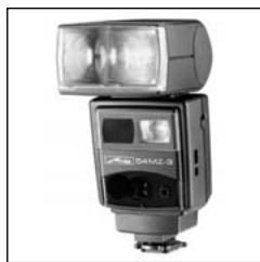
| Product type | Photographic flash |
| Brand | METZ |
| Model | MECABLITZ 45 CL-4 DIGITAL |
| Dimensions (L × H × D) | Approx. 92 × 247 × 102 mm |
| Weight (without power source) | Approx. 680 g |
| Guide number (ISO 100/21°, meters) | 45 |
| Power supply | 6 LR6 alkaline batteries (optional), NiMH battery pack 45-56 (supplied), Power Pack P50/P76 (optional) |
| Flash modes | TTL, TTL with measuring pre-flash, non-TTL automatic (A), manual (M), high-speed sync (HSS) |
| Automatic apertures (manual) | f/2.8 to f/16 for ISO 100 |
| Automatic aperture setting range (SCA 3002) | f/1.0 to f/45 for ISO 100 |
| Main reflector coverage | From 35 mm (24×36 format), with wide-angle diffuser from 28 mm |
| Reflector orientation | Vertical: 30°, 45°, 60°, 75°, 90°; horizontal: rotating |
| Color temperature | Approx. 5600 K |
| Flash duration | Approx. 1/125 s (full power) to 1/20000 s (low power) |
| Recycling time (full power) | Approx. 4 s (batteries or NiMH pack), 3 s (Power Pack) |
| Number of flashes (full power) | Approx. 200 flashes (NiMH pack), 170 (batteries), 300 (P50), 400 (P76) |
| Secondary reflector | Integrated, can be activated with adjustable power (100% or 50%) |
| Maintenance | Cleaning with a soft, dry cloth; capacitor reform every 3 months (turn on for 10 min) |
| Important safety instructions | Do not trigger near eyes; do not use near flammable gases; do not open (high voltage); use only authorized power sources |
| Optional accessories | SCA adapters (300/3002), connecting cables, diffusers, filters, power packs, stands, etc. |
Frequently Asked Questions - MECABLITZ 45 CL-4 DIGITAL METZ
User questions about MECABLITZ 45 CL-4 DIGITAL METZ
0 question about this device. Answer the ones you know or ask your own.
Ask a new question about this device
Download the instructions for your Camera Flash in PDF format for free! Find your manual MECABLITZ 45 CL-4 DIGITAL - METZ and take your electronic device back in hand. On this page are published all the documents necessary for the use of your device. MECABLITZ 45 CL-4 DIGITAL by METZ.
USER MANUAL MECABLITZ 45 CL-4 DIGITAL METZ
MECABLITZ 45 CL-4 digital
Bedienungsanleitung
Gebruiksaanwijzing
Manuale istruzioni
Mode d'emploi
Operating instruction
AbmaBe ca. in mm (B x H x T)
Blitzgerät 92 × 247 × 102
Gewicht:
in metersystem 45, in feetsystem 148
Flitsfuncties
Thank you for selecting a Metz product. We are very happy to welcome you as a customer.
It is only natural that you can't wait to start using your flash unit. However, it will be to your advantage if you take the time to read these Operating Instructions beforehand so that you are completely familiar with its operation.
Please open the picture cover page at the end of these Instructions.
This flash unit is suitable for:
- All cameras with a synchronising socket in conjunction with the supplied synchronising cable 45-47.
- All cameras with a flash shoe and a hot-shoe contact in conjunction with the supplied synchronising cable 45-54 (optional extra).
- System cameras
- Optimal adaptation to your system camera is achieved with an SCA adapter. Please refer to the enclosed SCA 300 / SCA 3002 Table to find out which adapter you require for your particular camera. Moreover, please refer to the operating instructions for the given SCA adapter for detailed information on the supported flash functions.
Contents
- Safety instructions 49
- Survey of the flash functions 51
3.Preparing the flash unit for use. 52 - Power supply 52
4.1 Operation with NiMh Battery Pack 45-56. 52
4.1.1 Battery notes 52
4.1.2 Connecting the charger to the mains 53
4.1.3Charging the batteries. 53
4.2 Operation with Power Pack P50 or P76 53 - Controls and displays 54
- Flash modes 54
6.1 Automatic flash mode 54
6.2 TTL flash mode 55
6.3 TTL flash mode with preflash 55
6.4 Manual flash mode M 56
6.5 Slave mode in the cordless Metz Remote System 56 - Bounce flash 57
- Illumination 57
- Fill-in flash 57
9.1 TTL fill-in flash 57
9.2 Automatic fill-in flash 57 - Exposure corrections 57
- Flash synchronisation 58
11.1 Normal synchronisation 58
11.2 2nd curtainsinchronisation 58
11.3 Slow synchronisation 58
11.4 High-speed synchronisation HSS 58 - Preflash function for red-eye reduction 58
- AF measuring beam 58
- Troubleshooting 58
- Maintenance and care. 59
- Technical data. 59
- Optional extras 60
1. Safety instructions
- The flash unit is intended and approved only for photographical use.
- NEVER fire a flash from a very short distance directly into the eyes of persons or animals. This can cause damage to the retina and may even lead to blindness.
- NEVER trigger a flash in the vicinity of flammable gases or liquids (petrol, solvents, etc.), since this may cause EXPLOSIONS!
- NEVER shoot flash pictures of car or bus drivers, cyclists or motorcyclists, or train drivers while the vehicle is moving! This may dazzle the person concerned and result in an accident.
- Only use the approved power sources specified in these operating instructions.
- NEVER attempt to open or short-circuit batteries!
- NEVER expose batteries to excessive temperatures such as intensive sunlight or a fire!
- Remove exhausted batteries immediately from the flash unit. Such batteries may leak, releasing chemicals which can damage the flash unit.
- NEVER attempt to recharge dry batteries!
- Do not expose the flash unit to dripping or splashing water.
- Do not expose your flash unit to high temperatures and humidity. Do not keep it in the glove compartment of your car.
- Do not touch the diffuser after firing several flashes at short intervals. Danger of burns!
- When taking flash shots at full light output and in rapid succession observe an interval of at least 3 minutes after 20 flashes.
- NEVER place material that is impervious to light in front of, or directly on the reflector. If this is not observed, the high energy of the flash light may cause burning or bleaching of the material or may damage the reflector.
-
NEVER dismantle the flash unit! DANGER: HIGH VOLTAGE! Repairs must only be completed by an authorised repair service.
-
Do not touch the contacts of the flash unit.
-
The flash unit must not be used if the case has been so badly damaged that internal components are exposed. Remove the batteries!
-
Do not use defective batteries!
-
The adapters for the various types of mains outlet socket may be inserted into the outlet socket only together with the battery charger! Never insert an adapter into an outlet socket on its own!
- The battery pack 45-56 may be charged only with the Metz battery charger 970! The use of unsuitable battery chargers can destroy the batteries and may result in fire or explosions!
- Use the battery charger only for charging the NiMH battery pack 45-56! Do not attempt to charge dry batteries or other types of rechargeable batteries with this charger!
- Do not short-circuit the contacts of the battery charger or the battery pack!
- The battery charger and the battery pack become warm during the charging operation and you should therefore ensure that they are suitably ventilated!
- Disconnect the battery charger from the mains voltage when it is not in use!
- Do not throw the battery pack into a fire, since it may explode if you do so!
- Use the battery charger only in a dry room. Keep it clean and dry!
Make sure that water cannot drip or splash onto the charger! - Do not use defective battery chargers or batteries! They may be repaired only by an authorised customer-service centre! Do not attempt to open the battery charger or the battery pack!
-
Clean the battery charger and the battery pack only with a soft, dry cloth!
-
Do not dispose of defective or unserviceable batteries with normal garbage! Contribute to the protection of the environment and take the batteries to a suitable collection centre!
- Protect the battery charger and the battery pack against high temperatures and moisture! Do not keep them in the glove compartment of your car!
- We accept no liability for malfunctions and damage to the battery charger or the battery pack which result from the use of accessories made by other manufacturers!
- Always switch off the flashgun before inserting or removing the battery pack!
-
Keep the battery charger and the battery pack out of the reach of children!
-
Survey of the flash functions
| SCA 3002 - System | SCA 300 - System | Standard foot SCA 301 or Synch cable 45-47 | A multitude of additional functions become available when the mecablitz 45CL-4 digital is operated with an SCA adapter of the SCA 3002 or SCA 300 system. This requires the connecting cable SCA 3045 (SCA 3002 and SCA 300 adapter) or the connecting cable SCA 300A (only SCA 300 adapter) as an optional accessory!Availability depends on the given camera system (camera manufacturer), the specific type of camera and the SCA adapter. For more detailed information please refer to the SCA Survey Table or the respective SCA Adapter Operating Instructions. |
| ● | ● | TTL flash mode (Standard-TTL) | |
| ● | Preflash measuring beam with TTL control (e.g. for Olympus and Sony) | ||
| ● | Red-eye reduction preflash | ||
| ● | ● | Manual TTL flash exposure correction | |
| ● | Canon E-TTL flash mode | ||
| ● | Canon FE flash exposure lock | ||
| ● | ● | Nikon matrix-controlled fill-in flash | |
| ● | Nikon 3D multi-sensor fill-in flash | ||
| ●/- | Nikon D-TTL / D-TTL-3D flash mode | ||
| ●/- | Nikon i-TTL / i-TTL-BL flash mode | ||
| ● | Nikon flash exposure lock | ||
| ●/- | Minolta TTL preflash mode / ADI | ||
| ● | ● | ● | Automatic flash mode |
| ● | ● | ● | Manual flash mode with partial light output settings |
| ● | Slave mode with simultaneous optical triggering with SCA 3083 digital | ||
| ● | Slave mode with preflash suppressions with SCA 3083 digital | ||
| ● | Slave mode in cordless Metz Remote System with SCA 3083 digital | ||
| ●/- | ●/- | ●/- | Manual / automatic aperture setting |
| ●/- | ●/- | ●/- | Manual / automatic ISO setting |
| ● | AF measuring beam control with connecting cable SCA 3045 | ||
| ● | ● | Flash readiness indication in camera's viewfinder or camera display | |
| ● | ● | Correct exposure indication in camera's viewfinder or camera display | |
| ● | ● | Automatic flash sync speed control | |
| ●/- | ●/- | ●/- | 1st/2nd curtain synchronisation (REAR; 2nd curtain)) |
| ● | ● | Slow synchronisation (Slow) | |
| ● | High-speed synchronisation (HSS) |
Table 1: Survey of the flash functions
3. Preparing the flash unit for use
Attaching the flash unit to the camera
The flash unit can be attached to the camera and operated with:
- a synch cable 45-47.
- a standard foot 301^1) and a synch cable SCA 300A^1)
- an SCA 3xx adapter1) and a synch cable SCA 300A1)
- an SCA 3xx2 adapter1) and a synch cable SCA 30451).
1) Optional extra
Be sure to switch off the flash unit by its main switch prior to mounting or removing the connecting components! Before mounting or removing the flash unit, switch off both the camera and the flash unit!
Mounting the flash unit:
- Push the SCA adapter or standard foot 301 into the camera's accessory shoe and lock in place with the knurled nut.
- Fasten the camera bracket with the bracket screw to the camera's tripod socket. For medium- and large-format cameras we recommend the use of the 70-35 bracket (optional extra).
- Insert the camera bracket into the mount ④ of the bracket holder ③ until it is audibly engaged.
- Secure the camera bracket with the locking screw.
- Connect the synch or connecting cable to the flash unit and camera or adapter.
4. Power supply
The flash unit can be operated with:
- 6 alkaline manganese batteries IEC LR 6 (AA-type) in the battery holder 45-39 (optional extra), or
- Metz NiMh battery pack 45-56, or
- Power Pack P 50 / P76 (optional extra)
Do not use lithium cells! Their higher voltage would damage the flash unit's electronic system. Only use the permitted power sources (see above). Warranty claims for faults and damage to the flash unit arenot accepted if they were caused by the use of accessories from other manufacturers.
Battery replacement
Press the two locking keys of the battery holder (optional extra) and pull the holder out of the flash unit (Fig 4a). To return the battery holder insert it into the flash unit's handle-mount grip and press it until it audibly locks in place.
Exchanging the batteries
Press together the two smooth locking keys of the dismantled battery holder (optional extra) and remove the lid (Fig. 4b). Insert new batteries in conformity with the polarity symbols indicated on the bottom of the holder. Return the lid and lock in again.
Mixed up battery poles may destroy the flash unit.. Replace all batteries at a time and make sure that the batteries are of the same brand and type and have the same capacity! Spent batteries must not be thrown into the domestic waste! Help keep the environment clean and discard spent batteries at corresponding collecting points.
4.1 Operation with NiMh Battery Pack 45-56
4.1.1 Battery notes
- The battery pack must be charged before it is used for the first time.
- The battery pack reaches its maximum capacity only after several charge/discharge cycles.
- Avoid deep-discharging of the battery pack. Never attempt to fully discharge the battery pack (with a lamp or similar load). Deep-discharging may destroy the battery pack.
- Rechargeable batteries discharge themselves gradually even if they are not used. The self-discharge rate increases at higher ambient temperatures. We therefore recommend that you store the battery pack at a temperature
of 2^ to 8^ (e.g. in a refrigerator).
- Keep the battery pack charged and recharge it at suitable intervals.
- Protect the battery pack against frost and heat!
4.1.2 Connecting the charger to the mains
The charger is supplied complete with interchangeable adapters for different mains sockets (Fig. 5). To change the adapter, disconnect the charger from the mains socket, release the currently installed adapter by pressing the key a and at the same time pull off the adapter y (Fig. 6).
With no adapter fitted, the battery charger can be connected to a mains socket with the aid of a mains cable (not included) which is inserted into the integrated mains connection socket (Fig. 7).
4.1.3 Charging the batteries
The NiMH battery pack 45-56 can be charged either in the flashgun or separately. If it is charged in the flashgun, the flashgun must be switched off!
DO NOT switch on the flash unit while the battery is being charged in the flash unit! The battery must only be charged with the original Metz battery charger envisaged for this purpose! DO NOT use any other charger!
The battery pack is exhausted if the recharging time after a full-power flash (e.g. in manual flash mode M) exceeds about 60 seconds.
The charging operation is monitored by a microcontroller in the battery charger. When the battery pack is fully charged, the charging operation is terminated automatically and the battery charger switches to trickle-charge mode.

You can leave the battery pack connected to the charger in order to ensure continuous readiness. However, if you do not intend to use the battery pack for a long period, you should disconnect it from the charger.
For safety reasons, the temperature of the battery pack is monitored during charging and the charging time is also limited by a timer. The charging time is about 2.5 hours for a fully discharged battery pack and correspondingly
shorter for a partially discharged battery pack.
- Connect the battery charger 970 to a mains outlet socket and to the battery pack (the connector for the charger is on the bottom of the pack). The charging operation starts automatically. The status of the battery charger is indicated by a two-colour LED.
LED lights with red light: the battery pack is being charged.
LED lights with green light: the battery pack has been fully charged and the charger has switched to trickle-charge mode.
Identifying a discharged battery pack 45-56:
move the ribbed slide on the battery cover to the black position.
Identifying a fully charged battery pack 45-56:
move the ribbed slide on the battery cover to the white position.
4.2 Operation with Power Pack P50 or P76
If the number of flashes and recycling times are not sufficient for your given application, then the flash unit can be powered with the Power Pack P50 or P76 (optional extra). The Power Pack is connected to the flash unit via the socket ⑤ with the V50 or V76 connecting cable (optional extra). This does not require the use of the battery holder 45-39 or the NiMh Battery Pack 45-56 inside the flash unit.
A loaded battery holder or battery pack can remain in the flash unit. To connect the Power Pack or the connecting cable V50 or V76 to the flash unit the main switch ⑨ of the flash unit must be pushed down into its lower position (OFF).
The flash unit will then be switched on and off with the switch on the Power Pack (see Operating Instructions for the Power Pack).
To protect the flash unit from overheating when it is operated with a Power Pack, a monitoring circuit lengthens the recycle time during intensive use! Ensure that all affected devices are switched off before connecting and disconnecting the connecting cable or the Power Pack!
5. Controls and displays
- Push the main switch ⑨ into the upper ON position and then switch on the flash unit.
The adjusted flash mode is indicated on the display window. The flash readiness indicator (8) lights up when the flash unit is ready for operation. The flash unit is switched off when the main switch is in the lower position. - The secondary reflector ② can be switched on with the switch for the secondary reflector, for instance for frontal fill-in when bouncing the flash. Push the switch ⑫ into the top position. When in the middle position the secondary reflector will only emit approx. 50% of its light intensity. The secondary reflector is turned off when the switch is in the bottom position.
- Set the ISO value of the camera or loaded film with the setting button for ISO sensitivity ⑤.
- Select the flash mode with the setting disk on the flash head. Adjust the setting mark for aperture pre-selection ④ to the required auto working aperture, TTL mode or M manual mode, or a manual partial light output.
- A flash can be fired with the manual firing button ⑦ when flash readiness is established. A full-power flash is fired in TTL and M mode. When in automatic flash mode or with manual partial light output the flash fired depends on the adjusted parameters (ISO / aperture / partial light output).
- The flash readiness indicator (8) lights up when the flash capacitor has become charged so that flashes can be fired. When an SCA adapter is being used the camera will automatically switch over to flash synch speed should this be necessary.
- The correct exposure indicator ⑩ lights up for approx. 3 sec. if the shot was correctly exposed in TTL or automatic flash mode. When an SCA adapter is used a corresponding indication is given in the camera's viewfinder or on the camera display, depending on the camera type.
- Further flash modes can be set for operation with a suitable system camera and an adapter from the SCA 3002 system (see Operating Instructions for the given camera and SCA adapter). The setting is made with the "Mode" key ⑪ . The adjusted flash mode is indicated on the indicator window.
6. Flash modes
6.1 Automatic flash mode
In the automatic flash mode A the sensor ② measures the light reflected by the subject. The flashlight is turned off by the flash unit's electronic circuit when the amount of light is adequate for the given exposure.
Setting procedure
- Set the ISO value of the camera or loaded film with the setting button ⑤ on the flash head.
- Adjust the setting mark for aperture pre-selection ④ on the flash head to the camera's f-stop. "A" lights up on the indicator window of the flash unit. The maximum flash range can be read off the setting mark of the selector disk. The shortest shooting distance is approx. 10% of the maximum flash range. The subject should be located in the middle third of the indicated range to give the electronic circuit leeway for compensation.
We recommend the camera mode aperture priority (A, Av) or manual (M).
Automatic setting of the ISO value and aperture
The aperture and ISO sensitivity of the camera can be automatically set on the flash unit when the latter is operated with an adapter from the SCA 3002 system:
The automatic setting range for ISO extends from ISO 6 to ISO 6400. The automatic setting range for the aperture extends from f/1.0 to f/45 (at ISO 100 / 21°), including all the in-between values.
- Equip the flash unit with the connecting cable SCA 3045 and appropriate adapter from the SCA 3002 system and connect to the camera.
- On the flash unit, set any auto working aperture with the setting mark for aperture pre-selection ⑭.
- Switch on the flash unit and the camera.
-
Lightly touch the camera's shutter release so that data can be exchanged between the camera and the flash unit.
-
Continue depressing the "Mode" key ⑪ until "A" and "B" appear on the indicator window. When the camera's shutter release is lightly touched the flash unit automatically takes over the data for the aperture and ISO setting from the camera. The values for auto working aperture and ISO manually adjusted on the flash unit are irrelevant in this context.
For manual adjustment of the ISO and aperture (e.g. with fill-in flash) continue depressing the "Mode" key ⑪ until only "A" is displayed on the display window.
6.2 TTL flash mode
In TTL flash mode the camera's sensor measures through-the-lens (TTL) the light reflected by the subject. This means that light measurement also takes mounted filters into account. When an adequate amount of light has been reached the camera's electronic circuit switches off the flash by way of the SCA adapter.
Setting procedure
- Equip the flash unit with the connecting cable SCA 3045 and a suitable adapter from the SCA 3002 system and connect to the camera. Adapters of the SCA 300 system can be connected to the flash unit with the connecting cable SCA 3045 or the connecting cable SCA 300A.
- Adjust TTL on the flash unit with the setting mark for aperture pre-selection ⑭.
- Switch on the flash unit and the camera. "TTL" is displayed on the indicator window.
The maximum flash range can be read off directly from the aperture calculator under the f-stop when the ISO value of the camera or film has been manually set on the flash unit. The shortest shooting distance is approx. 10% of the maximum flash range. The subject should be located in the middle third of the indicated range to give the electronic circuit leeway for compensation.
The aperture or ISO value does not have to be set on the flash unit for the TTL flash mode to function!
6.3 TTL flash mode with preflash
In TTL flash mode with preflash the reflective properties of the subject are established with one or more preflashes prior to exposure and evaluated by the camera's electronic circuit. The distance data from the camera's AF system can be additionally taken into account. Light output control by the camera's electronic system is via an adapter from the SCA 3002 system. The preflash mode is selected with the "Mode" key (1).
Many modern camera models, but particularly many digital cameras, only support the TTL flash mode with preflash (e.g. Canon E-TTL, Minolta ADI, Nikon D-TTL, Nikon iTTL etc.). These are further developments of the standard TTL flash mode which is not supported by these cameras. For further details please refer to the camera's operating instructions.
Setting procedure
- Equip the flash unit with the connecting cable SCA 3045 and a suitable adapter from the SCA 3002 system and connect to the camera.
- Set TTL on the flash unit with the setting mark for aperture pre-selection ④.
- Switch on the flash unit and the camera.
- Set the camera as explained in the camera's operating instructions.
- Lightly touch the camera's shutter release so that data can be exchanged between the camera and the flash unit.
- Continue depressing the "Mode" key ⑪ until the required flash mode is given on the indicator window (see subsequent Table).
| Adapter | Camera system | Flash modes | Display panel |
| SCA 3102 | Canon | E-TTL / E-TTL II | ETTL |
| SCA 3202 | Olympus | TTL with preflash | TTL |
| SCA 3302 | Minolta | "Preflash control" / "ADI" | TTL |
| SCA 3402 | Nikon | i-TTL / D-TTL | TTL |
| SCA 3402 | Nikon | i-TTL BL / D-TTL-3D | TTL BL |
| SCA 3402 | Nikon | "3D multi-sensor-fill-in flash" | TTL BL |
| SCA 3402 | Nikon | "Matrix-controlled fill-in flash" | TTL BL |
| High-speed synchronisation HSS | HSS |
The maximum flash range can be read off directly from the aperture calculator under the f-stop when the ISO value of the camera or film has been manually set on the flash unit. The shortest shooting distance is approx. 10% of the maximum flash range. The subject should be located in the middle third of the indicated range to give the electronic circuit leeway for compensation.
The aperture or ISO value does not have to be set on the flash unit for the TTL flash mode with preflash to function! All flash modes, with the exception of high-speed synchronisation (HSS), are also supported by the secondary reflector of the flash unit.
6.4 Manual flash mode M
The flash unit emits the full uncontrolled amount of light in the manual mode if no partial light output has been selected. Adaptation to the photographic situation may then be achieved with a corresponding aperture setting on the camera.
Setting procedure
-
Set the ISO value of the camera or film with the setting knob ⑤ on the flash head.
-
Set the setting mark "M" or manual partial light output (M1/2 - M1/4 - M1/8 - M1/16 - M1/32) with the setting mark of the selector disk ⑭ on the flash unit. "M" lights up on the indicator window of the flash unit.
The scale of the aperture calculator indicates, above the given lighting distance, the aperture that has to be set on the camera.
We recommend the camera mode aperture priority (A, Av) or manual (M). The adjusted aperture must be corrected when a wide-angle diffuser is used. The setting centre on the flash head automatically takes the mounted wide-angle diffuser into account.
6.5 Slave mode in the cordless Metz Remote System
When in the cordless Metz Remote System a controller flash unit (40 MZ..., 50 MZ5, 54 MZ...70 MZ..., 76 MZ...) on the camera provides cordless control of light output of one or more slave units in TTL or automatic flash mode.
TTL flash modes with preflash (ADI, E-TTL, D-TTL, i-TTL etc.) are not supported for system-inherent reasons!
The mecablitz 45 CL-4 digital supports the slave mode in the cordless Metz Remote System. For this purpose, the flash unit must be equipped with a slave adapter SCA 3083 digital (optional extra). The slave adapter is connected to the flash unit with the connecting cable SCA 3045 (optional extra).
Setting procedure
- Equip the flash unit with the connecting cable SCA 3045 and slave adapter SCA 3083 digital.
- Adjust the setting mark for aperture preselection ⑭ at TTL.
- Switch on the flash unit with the main switch. The slave mode is automatically activated. The AF auxiliary light in the connecting cable SCA 3045 flashes additionally when flash readiness is reached.
Please note that the mecablit 45 CL-4 digital only supports the remote channel "Ad1" of the controller! For further details relating to the slave mode please refer to the operating instructions for the slave adapter!
7. Bounce flash
Bounce flash illuminates the subject more softly and dense shadows are diminished. Moreover, the physically conditioned decline of light from the foreground to the background is reduced.
The main reflector ① of the flash unit can be swivelled horizontally and vertically for bounce flash. To avoid colour cast bounce the flash off a colour-neutral or white surface. The secondary reflector ⑥ can be additionally activated with the switch ② for fill-in frontal lighting.
Please note that bounce flash reduces the maximum flash range!
8. Illumination
The main reflector ① and the secondary reflector ⑥ cover focal lengths as of 35mm . The wide-angle diffuser (45-42) (included with the flash unit) widens the illumination of the main reflector for focal lengths as of 28mm (35 mm format in all cases). The wide-angle diffuser diminishes the guide number, and thus the maximum flash range, by approx. 30% . This is automatically adapted by the aperture calculator on the flash head.
9. Fill-in flash
9.1 TTL fill-in flash
Most camera models automatically support the TTL fill-in flash control when in Program or Auto Mode. Various camera models additionally feature special TTL fill-in flash programmes that can be activated on the camera (see the operating instructions for the given camera and SCA adapter).
9.2 Automatic fill-in flash
When in automatic fill-in flash mode the auto working aperture of the flash unit is opened by approx. one stop increment further than the f-stop set on the camera.
We suggest setting the camera in the aperture priority mode (e.g. A, Av) or in manual mode M. When an adapter from the SCA 3002 system is being used then manual aperture setting must be selected on the flash unit if corrections cannot be entered on the camera!
Example:
The aperture f/5.6 has been set on the camera. The aperture f/4 is manually set on the flash unit for fill-in flash.
With an adapter from the SCA 3002 system and an appropriate camera a correction value of approx. 1 f-stop is set on the camera for the flash during automatic data transfer (ISO, aperture). An additional setting on the flash unit is then not necessary!
10. Exposure corrections
Extreme contrast differences between subject and background can confuse the automatic exposure system of the camera or flash unit. This can be compensated by manual exposure correction.
Exposure correction in TTL flash mode must be set on the camera (see operating instructions for the given camera):
Dark subject against a bright background:
Positive correction value (approx. +1 to +2 f-stops).
Bright subject against a dark background:
Negative correction value (approx. -1 to -2 f-stops).
An f-stop which differs from the camera aperture is set manually on the flash unit for Exposure correction in automatic flash mode.
Dark subject against a bright background: Set on the flash unit an f-stop that is higher by one increment: e.g. camera aperture f/4; auto working aperture on the flash unit f/5.6.
Bright subject against a dark background: Set on the flash unit an f-stop that is lower by one increment: e.g. camera aperture f/4; auto working aperture on the flash unit f/2.8.
When an adapter from the SCA 3002 system is used in conjunction with a corresponding camera, the correction value for flash is set on the camera during automatic data transfer (ISO, aperture). An additional setting on the flash unit is then unnecessary!
When an adapter from the SCA 3002 system is used the manual aperture setting has to be selected on the flash unit if a correction value cannot be set on the camera!
11. Flash synchronisation
11.1 Normal synchronisation
With normal synchronisation the flash unit is fired at the beginning of the exposure time (synchronisation with the first shutter curtain). This is the standard mode with all cameras. A corresponding setting is therefore not necessary.
11.2 2nd curtainin synchronisation
Many cameras support 2nd curtain synchronisation (rear, 2nd curtain) in conjunction with an SCA adapter. The flash unit is fired at the end of the exposure time for a more "natural" rendition of the exposure situation in conjunction with slow shutter speeds (>1/30~s) and moving light sources. The light traces in the exposure then follow the light source. The setting is made on the camera. For further details please refer to the operating instructions for the given camera and SCA adapter.
11.3 Slow synchronisation
Slow synchronisation can be selected on many cameras when an SCA adapter is used. The camera will then adapt the shutter speed to the prevailing ambient light conditions so that in darkness greater emphasis will be placed on the background. The setting is made on the camera. For further details refer to the operating instructions for the camera and SCA adapter.
11.4 High-speed synchronisation HSS
In conjunction with an adapter from the SCA 3002 system, some cameras will support high-speed synchronisation (HSS) for flash shots at shutter speeds faster than the flash synch speed. For instance, HSS makes it possible to minimize the depth-of-field in portraiture with bright ambient light by selecting a wide open aperture to clearly contrast the portrait against the background. HSS is supported in TTL flash mode and/or manual flash mode M, depending on the camera model (see operating instructions for the given
camera and SCA adapter).
To set high-speed synchronisation continue depressing the "Mode" key ⑪ until "HSS" appears in the indicator window.
12. Preflash function for red-eye reduction
The red-eye effect becomes apparent when a person is looking straight into the camera, the ambient lighting is poor and the flash unit is located in the immediate vicinity of the camera. Under these circumstances the pupils are wide open so that the flash illuminates the red retina of the eyes.
One or more preflashes induce the pupils to close down, thereby reducing the red-eye effect. This function is set on the camera (see operating instructions for the given camera and SCA adapter).
13. AF measuring beam
When using an SCA adapter from the SCA 3002 system in conjunction with the SCA 3045 connecting cable (optional extra), and depending on the given camera model, the AF measuring beam function is activated in poor lighting conditions. A strip pattern is projected onto the subject to enable the AF system to focus the camera lens. The distance range depends on the speed of the lens. With a standard lens the effective range is between approx. 0.7m and 6 to 9m (for further details please refer to the operating instructions of the given camera and SCA adapter).
14. Troubleshooting
Should, for example, the flash unit not work properly in the individual modes, then switch off the flash unit for about 10 seconds by its main switch. Check the camera settings and find out if the SCA adapter or the flash unit's foot is correcty mounted in the camera's accessory shoe.
Replace the old batteries or rechargeable battery packs by new ones.
The flash unit must operate properly when it is switched on again. Contact your local dealer should this not be the case.
15. Maintenance and care
Remove any grime and dust with a soft, dry or silicon-treated cloth. Never use detergents – they may damage plastic parts.
Forming the flash capacitor
The flash capacitor incorporated in the flash unit undergoes a physical change when the flash unit is not switched on for prolonged periods. For this reason it is necessary to switch on the flash unit for approx. 10 minutes every 3 months. The batteries must supply sufficient power for flash readiness to be indicated within 1 minute after the flash unit was switched on.
16.Technical data
Guide numbers at ISO 100/21:
in the metric system: 45 in the imperial system: 148
Flash modes
TTL, TTL modes with preflash (see Table 1), Auto Mode A, Manual Mode M, high-speed synchronisation HSS
Manually adjustable auto apertures:
f2.8-f4-f5,-f8-f11-f16 at ISO 100/21°
Automatic aperture setting range
f1.0 to f45 (at ISO 100 / 21°) including in-between values (SCA 3002)
Flash durations:
- approx. 1/125 ... 1/20000 sec.
- in M mode approx. 1/125 sec. with full light output
- with 1/2 light output approx. 1/800 sec.
- with 1/4 light output approx. 1/2000 sec.
- with 1/8 light output approx. 1/3500 sec.
- with 1/16 light output approx. 1/6000 sec.
- with 1/32 light output approx. 1/10000 sec
Coverage of sensor: approx. 25^
Colour temperature: approx. 5600 K
Sensitivity:
ISO 25 to ISO 1000 for manual setting
ISO 6 to ISO 6400 for automatic setting (SCA 3002)
Synchronisation: Low-voltage IGBT ignition
Number of flashes:
- approx. 200 with NiMh batteries 45-56
- approx. 170 with high-capacity alkaline manganese batteries
- approx. 300 with Power Pack P50
- approx. 400 with Power Pack P76
(all at full light output)
Recycling time:
- approx. 4 sec. with high-capacity alkaline manganese batteries
- approx. 4 sec. with NiMh batteries 45-56
- approx. 3 sec. with Power Pack P50 / P76
(all at full light output)
Flash coverage
Main reflector, as of 35 mm (35 mm format)
... with wide angle diffuser, as of 28 mm (35 mm format)
Secondary reflector, as of 35 mm (35 mm format)
Swivelling ranges and locking positions of main reflector
upwards 15^ 30^ 45^ 60^ 75^ 90^
counter-clockwise 90^ 180°
clockwise 90^ 180°
Dimensions approx. in mm (w x h x d)
Flash unit 92 × 247 × 102
Weight:
Flash unit without power sources: approx. 680 g
Table 2: Guide numbers at maximum light output (Pag. 96)
Table 3: Distances in TTL flash mode (Pag. 97)
-
. . 16 Distance range without wide-angle diffuser
-
. . 11 Distance range with wide-angle diffuser
These table does not apply to bounced flash.
Battery charger 970
Input: 100 - 240 V (50-60 Hz) 0.6 A
Output: 4,8-9,6 V 0,8 A (charging current)
Battery pack 45-56
Rated voltage/capacity: 7.2V/1650 mAh
Included
Flash unit, camera bracket, battery pack 45-56, charger, synch cable 45-47, wide-angle diffuser 45-42, operating instructions.
17. Optional extras
Malfunctions and damage caused to the flash unit due to the use of accessories from other manufacturers are not covered by our guarantee.!.
- Adapter of the system SCA 300
For flash operation with system cameras. See separate Operating Instructions. Connecting cable SCA 300A (Order No. 0000930) or connecting cable SCA 3045 are additionally required.
- Adapter of the system SCA 3002
For flash operation with system cameras with digital data transmission of the SCA functions. Extended functional features compared with the SCA 300 system. The SCA 3045 connecting cable is additionally required.
- Connecting cable SCA 3045 (Order No. 000304500)
Connects the flash unit to adapters of the systems SCA 3002 and SCA 300.
- Battery Holder 45-39 (Order No. 000045394)
For dry cell batteries.
- Filter set 45-32 (Order No. 000045327)
Consists of a set of 4 colour effect filters and 1 clear filter to hold any coloured foil.
B 46 charger set (Order No. 000129464)
NiMh battery and charger to convert the 45 CL-4 digital to NiMh battery operation.
Mecalux 11 (Order No. 0000011)
Sensor for optical, delay-free remote firing of slave flash units by a camera-triggered flash. Responds also to infrared light beam. Does not require batteries.
- Mecalux Holder 60-26 (Order No: 000060264)
To mount the Mecalux 11.
- NiMh battery 45-56 (Order No. 000045569)
for NiMh battery operation of the 45CL-4 digital
- Mecabounce 45-90 (Order No. 000045908) With this diffuser, soft lighting can be achieved in a very simple manner. It gives your pictures a marvellous soft appearance, while the tone of skin is rendered faithfully. The maximum working range is diminished by the factor 2 in conformity with the loss of light.
- Power-Pack P76 (Order No. 000129768) For a high number of flashes and short recycling times (abt 400 full-power flashes). To connect the P 76, the V76 connecting cable (Order No. 0000376) is additionally required.
- Connecting cable V76 (Order No.000003762) to connect the P50 or P76.
- Bounce diffuser 60-33 (Order No. 000060334) To soften heavy shadows with reflected light.
- Camera bracket 70-35 (Order No. 000070353) For firm fastening of medium- and large-format cameras.
- Standard foot 301 (Order No. 000093014) In conjunction with SCA 300, for connection to the accessory shoe of cameras with hot shoe contact.
- Slave-Adapter SCA 3083 digital (Order No. 000330838) To operate the 45 CL-4 digital as a slave flash unit in the cordless Metz Remote System, for optical simultaneous triggering and optical triggering with preflash suppression for digital cameras. The SCA 3045 connecting cable is additionally required (Order No. 0030450).
- Synch leads:
- Coiled synch lead 45-49 (Order No: 000045499)
- Coiled synch lead 45-54 for hot shoe (Order No: 000045542)
- Synch lead 45-48, 1 m (Order No: 000045480)
- Synch extension lead 60-54 (5 m) (Order No: 000060541)
-
Bracket adapter 60-28 (Order No. 0006028) For parallax correction of reflector and camera with close-ups and wide-angle shots.
-
Carrying strap 50-31 (Order No. 000050315)
- Connecting cable SCA 300 A (Order No. 000093057) Connects the flash unit to adapters of the SCA 300 system.
Disposal of batteries
Do not dispose of spent batteries with domestic rubbish.
Please return spent batteries to collecting points should they exist in your country. Please return only fully discharged batteries. Normally, batteries are fully discharged if:
- The device they powered switches itself off and indicates "Spent batteries".
- They no longer function properly after prolonged use.
To ensure short-circuit safety please cover the battery poles with adhesive tape.
Premessa
A工程技术, a design of the camera.
Your Metz product was developed and manufactured with high-quality materials and components which can be recycled and/or re-used.

This symbol indicates that electrical and electronic equipment must be disposed of separately from normal garbage at the end of its operational lifetime.
Please dispose of this product by bringing it to your local collection point or recycling centre for such equipment.
This will help to protect the environment in which we all live.

Within the framework of the CE approval symbol, correct exposure was evaluated in the course of the electromagnetic compatibility test.

Do not touch the SCA contacts!
In exceptional cases the unit can be damaged if these contacts are touched.

Avertenza:
Fig. 4b: Opening the battery housing (only with BAT-version, otherwise optional extra)
Consumer electronics
Photoelectronics
Plastics technology
Industrial electronics
Metz. Always first class.

C E
704 47 0126.A5
D F NL GB I E
- MECABLITZ 45 CL-4 digital
- Gewicht:
- Please open the picture cover page at the end of these Instructions.
- This flash unit is suitable for:
- Contents
- Safety instructions
- Preparing the flash unit for use
- Attaching the flash unit to the camera
- Mounting the flash unit:
- Power supply
- Battery replacement
- Exchanging the batteries
- Operation with NiMh Battery Pack 45-56
- Battery notes
- Connecting the charger to the mains
- Charging the batteries
- Operation with Power Pack P50 or P76
- Controls and displays
- Flash modes
- Automatic flash mode
- Setting procedure
- Automatic setting of the ISO value and aperture
- TTL flash mode
- TTL flash mode with preflash
- Manual flash mode M
- Slave mode in the cordless Metz Remote System
- Bounce flash
- Illumination
- Fill-in flash
- TTL fill-in flash
- Automatic fill-in flash
- Exposure corrections
- Dark subject against a bright background:
- Bright subject against a dark background:
- Flash synchronisation
- Normal synchronisation
- 2nd curtainin synchronisation
- Slow synchronisation
- High-speed synchronisation HSS
- Preflash function for red-eye reduction
- AF measuring beam
- Troubleshooting
- Maintenance and care
- Forming the flash capacitor
- 16.Technical data
- Optional extras
- Disposal of batteries
- Premessa
- Do not touch the SCA contacts!
- Avertenza:
Brand : METZ
Model : MECABLITZ 45 CL-4 DIGITAL
Category : Camera Flash