WOLFDALE1333-GLAN-M - Motherboard ASROCK - Free user manual and instructions
Find the device manual for free WOLFDALE1333-GLAN-M ASROCK in PDF.
Download the instructions for your Motherboard in PDF format for free! Find your manual WOLFDALE1333-GLAN-M - ASROCK and take your electronic device back in hand. On this page are published all the documents necessary for the use of your device. WOLFDALE1333-GLAN-M by ASROCK.
USER MANUAL WOLFDALE1333-GLAN-M ASROCK
Copyright Notice: No part of this installation guide may be reproduced, transcribed, transmitted, or trans- lated in any language, in any form or by any means, except duplication of documen- tation by the purchaser for backup purpose, without written consent of ASRock Inc Products and corporate names appearing in this guide may or may not be registered trademarks or copyrights of their respective companies, and are used only for identifica- tion or explanation and to the owners’ benefit, without intent to infringe. Disclaimer: Specifications and information contained in this guide are furnished for informational use only and subject to change without notice, and should not be constructed as à commitment by ASRock. ASRock assumes no responsibility for any errors or omissions that may appear in this guide With respect to the contents of this guide, ASRock does not provide warranty of any kind, either expressed or implied, including but not limited to the implied warranties or conditions of merchantability or fitness for a particular purpose. In no event shall ASRock, its directors, officers, employees, or agents be liable for any indirect, special, incidental, or consequential damages (including damages for loss of profits, loss of business, loss of data, interruption of business and the like), even if ASRock has been advised of the possibility of such damages arising from any defect or error in the guide or product.
This device complies with Part 15 ofthe FCC Rules. Operation is subject to the following two conditions: (1) this device may not cause harmful interference, and (2) this device must accept any interference received, including interference that may cause undesired operation
CALIFORNIA, USA ONLY
The Lithium battery adopted on this motherboard contains Perchlorate, à toxic substance controlled in Perchlorate Best Management Practices (BMP) regulations passed by the California Legislature. When you discard the Lithium battery in California, USA, please follow the related regulations in advance “Perchlorate Material-special handling may apply, see www. dtsc.ca.gov/hazardouswaste/perchlorate" ASRock Websit : http/Www.asrock.com Published October 2007 Copyright@2007 AS Rock INC. All rights reserved ASRock Wolfdale1333-GLAN/M Motherboard English
- If you use 2-channel speaker, please connectthe speakers plug into “Front Speaker | ack”. See the table below for connection details in accordance with the type of speaker you use. TABLE for Audio Output Connection Audio Output Channels [Front Speaker | Rear Speaker | Cental/Bass | Side Speaker (No. 7) (No. 4) (No. 5) (No. 3) 2 V = = = 4 v v E 6 v v v = 8 v v v v #To enable Mult-Streaming function, you need to connect a front panel audio cable to the front panel audio header. After restarting your computer, you wil find “Mixer tool on your system. Please select “Mixer ToolBox" EI , click “Enable playback multi-streaming”, and click English “ok. Choose 2H", "4CH" "6CH”, or “CH” and then you are allowed to select “Realtek HDA Primary output’ to use Rear Speaker, Central/Bass, and Front Speaker, or select ‘Realtek HDA Audio 2nd output” to use front panel audio. ASRock Wolfdale1333-GLAN/M Motherboard
Thank you for purchasing AS Rock Wolfdale1333-GLAN/M motherboard, a reliable moth- erboard produced under ASRock's consistentiy stingent quality control. It delivers excellent performance with robust design conforming to ASRock's commitment to quality and endurance. This Quick Installation Guide contains introduction of the motherboard and step-by- step installation guide. More detailed information of the motherboard can be found in the user manual presented in the Support CD. be updated, the content of this manual will be subject to change without notice. In case any modifications of this manual occur, the updated version will be available on ASRock website without further notice. You may find the latest VGA cards and CPU support lists on ASRock website as well. ASRock website http:/www.asrock.com If you require technical support related to this motherboard, please visit our website for specific information about the model you are using. www.asrock.com/supportiindex.asp ? Because the motherboard specifications and the BIOS software might
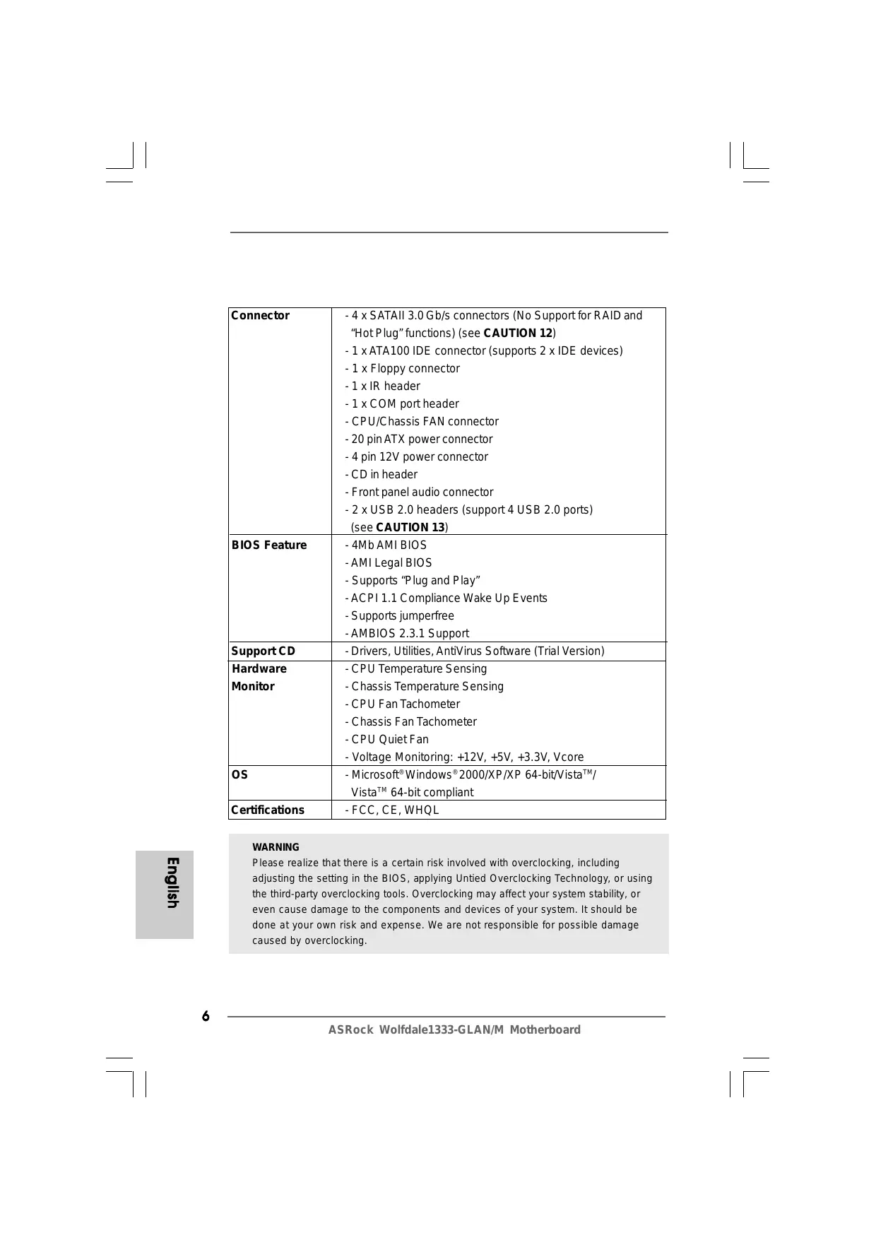
usiIôu3 Connector = 4x SATAI 3.0 Gb/s connectors (No Support for RAID and “Hot Plug” functions) (see CAUTION 12) - 1 XATA100 IDE connector (supports 2 x IDE devices) - 1x Floppy connector -1xIR header - 1x COM port header - CPU/Chassis FAN connector - 20 pin ATX power connector -4 pin 12V power connector - CD in header - Front panel audio connector -2xUSB 2.0 headers (support 4 USB 2.0 ports) {see CAUTION 13) BIOS Feature -4MbAMI BIOS - AMI Legal BIOS - Supports “Plug and Play” -ACPI 1.1 Compliance Wake Up Events - Supports jumperfree -AMBIOS 2.3.1 Support SupportCD - Drivers, Utilities, AntiVirus Software (Trial Version) Hardware - CPU Temperature Sensing Monitor - Chassis Temperature Sensing - CPU Fan Tachometer - Chassis Fan Tachometer - CPU QuietFan - Voltage Monitoring: +12V, +5V, +3.3V, Vcore os - Microsoft® Windows®2000/XP/XP 64-bitVista®"/ Vista”" 64-bit compliant Certifications -FCC, CE, WHQL WARNING Please realize that there is a certain risk involved with overclocking, including adjusting the setting in the BIOS, applying Untied Overclocking Technology, or using the third-party overclocking tools. Overclocking may affect your system stability, or. even cause damage to the components and devices of your system. it should be done at your own risk and expense. We are not responsible for possible damage caused by overclocking. ASRock Wolfdale1333-GLAN/M Motherboard
FSB1333-CPU will operate in overclocking mode. Under this situation, PCIE frequency will also be overclocked to 115MHz. About the setting of “Hyper Threading Technology", please check page 29 of “User Manual” in the support CD. This motherboard supports Untied Overclocking Technology. Please read *Untied Overclocking Technology" on page 21 for details This motherboard supports Dual Channel Memory Technology. Before you implement Dual Channel Memory Technology, make sure to read the installation guide of memory modules on page 12 for proper installation. There are memory module installation limitations on this motherboard, please read “Installation of Memory Modules (DIMM)" on page 12 for details. Please check the table below for the CPU FSB frequency and its corre- sponding memory support frequency. CPU FSB Frequency | Memory Support Frequency 1333 DDRII533*, DDRII667 1066 DDRII533, DDRII667
533 DDRII400, DDRII533
- When you use a FSB1333-CPU on this motherboard, it will run at DDRII500 if you adopt a DDRII533 memory module. Due to the chipset limitation, the actual memory size may be less than 4GB for the reservation for system usage under Windows® XP, Windows" XP 64-bit, Windows” Vista!" and Windows” Vista!” 64-bit. Although this motherboard offers stepless control, is not recommended to perform over-clocking. Frequencies other than the recommended CPU bus frequencies may cause the instability of the system or damage the CPU. While CPU overheat is detected, the system will automatically shutdown. Before you resume the system, please check if the CPU fan on the motherboard functions properiy and unplug the power cord, then plug it back again. To improve heat dissipation, remember to spray thermal grease between the CPU and the heatsink when you install the PC system. The maximum shared memory size is defined by the chipset vendor and is subjectto change. Please check Intel” website for the latest information. For microphone input, this motherboard supports both stereo and mono modes. For audio output, this motherboard supports 2-channel, 4-channel, 6-channel, and 8-channel modes. Please check the table on page 3 for proper connection. Before installing SATAII hard disk to SATAII connector, please read the “S ATAII Hard Disk Setup Guide” on page 20 to adjust your SATAII hard disk drive to SATAII mode. You can also connect SATA hard disk to SATAII connector directiy. Power Management for USB 2.0 works fine under Microsoft® Windows® Vista! 64-bit/ Vista!" / XP 64-bit/ XP SP1 or SP2 / 2000 SP4. ASRock Wolfdale1333-GLAN/M Motherboard English
Vista'“ Premium 2007 and Basic Logo For system integrators and users who purchase this motherboard and plan to submit Windows® Vista" Premium 2007 and Basic logo, please follow below table for minimum hardware requirements. CPU Celeron D 326 Memory 512MB x 2 Dual Channel (Premium) 512MB Single Channel (Basic) 256MB x 2 Dual Channel (Basic) VGA DX9.0 with WDDM Driver *f you plan to use onboard VGA to submit Windows? Vista" logo, please keep the default setting of"DVMT Mode Select” option under BIOS
- If you plan to use extemal graphics card on this motherboard, please refer to Premium Discrete requirement at http:/{ww.asrock.com
- After June 1, 2007, all Windows® Vista systems are required to meet above minimum hardware requirements in order to qualify for Windows” Vista" Premium 2007 logo. usilôuz ASRock Wolfdale1333-GLAN/M Motherboard
2.Installation Pre-installation Precautions Take note of the following precautions before you install mother- board components or change any motherboard settings. Unplug the power cord from the wall socket before touching any component. Failure to do so may cause severe damage to the motherboard, peripherals, and/or components. To avoid damaging the motherboard components due to static electrcity, NEVER place your motherboard directly on the carpet or the like. Also remember to use a grounded wrist strap or touch à safety grounded object before you handle components. Hold components by the edges and do not touch the ICS. Whenever you uninstall any component, place it on à grounded antstatic pad or in the bag that comes with the component. When placing screws into the screw holes to secure the motherboard to the chassis, please do not over-tighten the screws! Doing so may damage the motherboard
2.1 CPU Installation
For the installation of Intel 775-LAND CPU, please follow the steps below.
775-Pin Socket Overview Before you insert the 775-LAND CPU into the socket, please check if the CPU surface is unclean or if there is any bent pin on the socket. Do not force to insertthe CPU into the socket if above situation is found. Otherwise, the CPU will be seriously damaged ASRock Wolfdale1333-GLAN/M Motherboard English
Step 1. Open the socket: Step 1-1. Disengaging the lever by depressing down and out on the hook to clear S retention tab. Ê DA Ÿ JE Step 1-2. Rotate the load lever to fully open po- sition at approximately 135 degrees. Step 1-3. Rotate the load plate to fully open po- sition at approximately 100 degrees. Step 2. Insertthe 775-LAND CPU: Step 2-1. Hold the CPU by the edges where are marked with black lines. Step 2-2. Orientthe CPU with IHS (Integrated Heat Sink) up. Locate Pinl and the two orientation key notches. Pini — orientation key notch , TI5-Pin Socket TISLAND CPU For proper inserting, please ensure to match the to orientation key notches of the CPU with the two alignment keys ofthe socket Step 2-3. Carefully place the CPU into the socket by using a purely vertical motion. Step 2-4. Verifythatthe CPU is within the socket and properly mated to the orient keys. yslôua Step 3. Remove PnP Cap (Pick and Place Cap): Use your left hand index finger and thumb to support the load plate edge, engage PnP cap with right hand thumb and peel the cap from the socket while pressing on center of PnP cap to assist in removal. ASRock Wolfdale1333-GLAN/M Motherboard
À 1. itis recommended to use the cap tab to handle and avoid kicking offthe PnP cap
2. This cap must be placed if retuming the motherboard for after
service. Step 4. Close the socket Step 4-1. Rotate the load plate onto the IHS Step 4-2. While pressing down lightiy on load plate, engage the load lever. Step 4-3. Secure load lever with load plate tab under retention tab of load lever.
2.2 Installation of CPU Fan and Heatsink
For proper installation, please kindly refer to the instruction manuals of your CPU fan and heatsink. Below is an example to illustrate the installation of the heatsink for 775-LAND CPU. Step 1. Apply thermal interface material onto center of IHS on the socket surface. NS Step 2. Place the heatsink onto the socket. Ensure SE fan cables are oriented on side closest to the CPU fan connector on the motherboard (CPU_FANI, see page 2, No. 3). Step 3. Align fasteners with the motherboard throughholes Step 4. Rotate the fastener clockwise, then press down on fastener caps with thumb to install and lock. Repeat with remaining fasteners. If you press down the fasteners without rotating them clockwise, the heatsink cannot be secured on the motherboard English Step 5. Connect fan header with the CPU fan connector on the motherboard. Step 6. Secure excess cable with tie-wrap to ensure cable does not interfere with fan operation or contact other components. ASRock Wolfdale1333-GLAN/M Motherboard
2.3 Installation of Memory Modules (DIMM)
Wolfdale1333-GLAN/M motherboard provides four 240-pin DDRII (Double Data Rate
11) DIMM slots, and supports Dual Channel Memory Technology. For dual channel
configuration, you always need to install identical (the same brand, speed, size and chip-type) DDRII DIMM pair in the slots of the same color. In other words, you have to install identicalDDRIIDIMM pair in Dual Channel A (DDRIL_ 1 and DDRII_ 3; Yellow slots; see p.2 No.7) or identical DDRII DIMM pair in Dual Channel B (DDRIL_2 and DDRII_4; Orange slots; see p.2 No.8), so thatDual Channel Memory Technology can be activated. This motherboard also allows you to install four DDR II DIMMS for dual channel configuration, and please install identical DDRII DIMMS in all four slots. You may refer to the Dual Channel Memory Configuration Table below. Dual Channel Memory Configurations (DS: Double Side, SS: Single Side)
If you want to install two memory modules, for optimal compatibility and reliability, it is recommended to install them in the slots of the same color. In other words, install them either in the set of yellow slots (DDRII_1 and DDRIL_3), orin the set of orange slots (DDRII_2 and DDRII_4) If only one memory module or three memory modules are installed in the DDRII DIMM slots on this motherboard, itis unable to activate the Dual Channel Memory Technology. If a pair of memory modules is NOT installed in the same Dual Channel, for example, installing a pair of memory modules in DDRIL_1 and DDRIL_2, it is unable to activate the Dual Channel Memory Technology . Itis not allowed to install a DDR memory module into DDRII slot; otherwise, this motherboard and DIMM may be damaged. ASRock Wolfdale1333-GLAN/M Motherboard
- If you only install one memory module, you can install it to any one of the four slots These two TRANSCEND memory modules can only be supported under the following conditions: DRAM SIZE [TYPE CELL CELL NO. SINGLE SIDE /
slot of this motherboard.
2. If you plan to install two above memory modules, it is recommended to
instal them either in the set of yellow slots (DDRIL_1 and DDRIL_ 3), orin the set of orange slots (DDRII_2 and DDRII_4).
3. This motherboard does not support three or four above memory modules.
Installing a DIMM Please make sure to disconnect power supply before adding or removing DIMMs or the system components. Step 1. Unlock a DIMM slot by pressing the retaining clips outward. Step 2. Align a DIMM on the slot such that the notch on the DIMM matches the break on the slot. e) English ASRock Wolfdale1333-GLAN/M Motherboard
usil6uz The DIMM only fits in one correct orientation. It will cause permanent damage to the motherboard and the DIMM if you force the DIMM into the slot at incorrectorientation. Step 3. Firmly insertthe DIMM into the slot until the retaining clips at both ends fully snap back in place and the DIMM is properly seated.
2.4 Expansion Slots (PCI, HDMR and PCI Express Slots)
There are 2 PCI slots, 1 HDMR slot and 2 PCI Express slots on this motherboard. PCislots: PCI slots are used to install expansion cards that have the 32-bit PCI interface. HDMR slot: HDMR slot is used to insert a HDMR card with v.92 Modem functionality. The HDMR slot is shared with PCI2 slot. PCIE slots: PCIE1 (PCIE x16 slot) is used for PCI Express cards with x16 lane width graphics cards. PCIE2 (PCIE x1 slot) is used for PCI Express cards with x1 lane width cards, such as Gigabit LAN card, SATA2 card, etc. the onboard VGA will be disabled. If you install the add-on PCI Express VGA card to PCIE1 (PCIE x16 slot) and adjust the ‘Internal Graphics Mode Select’ BIOS option to [Enabled], the onboard VGA will be enabled, and the primary screen will be onboard VGA. ! } If you install the add-on PCI Express VGA card to PCIE1 (PCIE x16 slot), Installing an expansion card Step 1. Before installing the expansion card, please make sure thatthe power supply is switched off or the power cord is unplugged. Please read the documentation ofte expansion card and make necessary hardware settings for the card before you start the installation. Step 2. Remove the bracket facing the slotthat you intend to use. Keep the screws for later use. Step 3. Align the card connector with the slot and press firmly until the card is com- pletely seated on the slot. Step 4. Fasten the card to the chassis with screws. ASRock Wolfdale1333-GLAN/M Motherboard
The illustration shows how jumpers are setup. When the jumper cap is placed on pins, the jumper is “Short”. If no jumper cap 4 is placed on pins, the jumper is “Open”. The illustration shows à 3-pin jumper whose pinl LT] G LE and pin2 are “Short” when jumper cap is Short Open placed on these 2 pins. Jumper Setting Description PS2_USB_PWR1 12 23 Short pin2, pin3 to enable {see p2 No.1) OS) cc +5VSB (standby) for PS/2 +5V +5vsB or USB wake up events Note: To select +5VSB, it requires 2 Amp and higher standby current provided by power supply. Clear CMOS (CLRCMOS Zi jumpe Co (see p2 No.6) 2-pin jumper Note: CLRCMOS1 allows you to clear the data in CMOS. The data in CMOS includes system setup information such as system password, date, time, and system setup parameters. To clear and resetthe system parameters to default setup, please turn off the computer and unplug the power cord from the power supply. After waiting for 15 seconds, use a jumper cap to short 2 pins on CLRCMOS1 for 5 seconds. English ASRock Wolfdale1333-GLAN/M Motherboard
2.6 Onboard Headers and Connectors
Onboard headers and connectors are NOT jumpers. Do NOT place jumper caps over these headers and connectors. Placing jumper caps overthe headers and connectors will cause permanent damage of the motherboard! FDD connector G3-pnFLOPPY1) (ee p2 No.20) Pit FLOPPY1 bcssrpes sidetoPinl Note: Make sure the red-striped side of the cable is plugged into Pin1 side of the connector. Primary IDE connector (Blue) (9-in IDE, see p2 No. 10) IDE1 PIN connect the blue end D: SEEN connect the black end to the motherboard *® “ tothe IDE devices 80-conductor ATA 66/100 cable Note: Please refer to the instruction of your IDE device vendor for the details. Serial ATAII Connectors These Serial ATAII (SATAII) (SATAIL 1:56 p.2,N0. 16) connectors support SATAII GAL2sep2Ne nd Goes sance Of SATA hard disk for internal (SATAIL 3:5e p.2,N0.15) storage devices. The current SATAI interface allows up to
(SATAIL_4:see p.2, No. 13) SATAIL1 SATAIL2 Serial ATA (SATA) Either end ofthe SATA data cable Data Cable can be connected to the SATA / {Optional) SATAII hard disk or the SATAII connector on the motherboard. Serial ATA (SATA) Please connect the black end of Power Cable D SATA power cable to the power
{Optional) ) connector on each drive. Then connect tothe SATA connect the white end of SATA HODpowercomecor À ue power cable to the power powersupoly connector of the power supply. ASRock Wolfdale1333-GLAN/M Motherboard
USB 2.0 Headers we» Besides four default USB 2.0 (pin USB6_7) ports on the 1/0 panel, there are (see p2 No.18) two USB 2.0 headers on this motherboard. Each USB 2.0 header can support two USB
(pin USB4_5) (see p.2 No. 19) Oum Infrared Module Header (Spin R2) This header supports an (see p.2 No. 30) optional wireless transmitting and receiving infrared module. Internal Audio Connector This connector allows you {-pin CD1) a CD-ROM, DVD-ROM,TV tuner card, or MPEG card. to receive stereo audio input (CDI:See p2 No.24) Ci] co from sound sources such as Front Panel Audio Header (S-pin HD_AUDIO1) (see p.2 No.22) convenient connection and control of audio devices. À 1. High Definition Audio supports Jack Sensing, but the panel wire on the chassis must support HDA to function correctiy. Please follow the instruction in our manual and chassis manual to install your system. . if you use AC'97 audio panel, please install it to the front panel audio header as below: A. Connect Mic_IN (MIC) to MIC2_L. B. Connect Audio_R (RIN) to OUT2_R and Audio_L (LIN) to OUT2_L. C. Connect Ground (GND) to Ground (GND). D. MIC_RET and OUT_RET are for HD audio panel only. You don't need to connect them for AC'97 audio panel. Enter BIOS Setup Utility. Enter Advanced Settings, and then select Chipset Configuration. Set the Front Panel Control option from Auto] to [Enabled]. This is an interface for front panel audio cable that allows ASRock Wolfdale1333-GLAN/M Motherboard English
MOTTE) F. Enter Windows system. Click the icon on the lower right hand taskbar to enter Realtek HD Audio Manager. Click ‘Audio 1/0", select “Connector Settings" , choose “Disable front panel jack detection”, and save the change by clicking “OK”. System Panel Header (9-pin PANEL1) (see p2 No.12) This header accommodates several system front panel functions Chassis Speaker Header {a-pin SPEAKER 1) (seep2 No.l1) Please connect the chassis speaker to this header. Chassis Fan Connector (G-pin CHA_FAN2) (see p2 No.17) seeec Please connect a chassis fan cable to this connector and match the black wire to the ground pin. CPU Fan Connector ” PÉpu.ran speeo {pin CPU_FANT) s JAN SPEED CoNIROL (see p2 No.3) Bs<9
Please connect a CPU fan cable to this connector and match the black wire to the ground pin. A Though this motherboard provides 4-Pin CPU fan (Quiet Fan) support, the 3-Pin CPU fan still can work successfully even without the fan speed control function If you plan to connect the 3-Pin CPU fan to the CPU fan connector on this motherboard, please connect it to Pin 1-3. Pin1:3Connected | 3-Pin Fan Installation ATX Power Connector (20-pinATXPWR1) (see p.2 No.27) Please connect an ATX power supply to this connector. ATX 12V Connector pin ADAVI) {see p.2 No.2) Please note that it is necessary to connect a power supply with ATX 12V plug to this connector so that it can provides sufficient power. Failing to do so will cause the failure to power up ASRock Wolfdale1333-GLAN/M Motherboard
Before installing SATAII hard disk to your computer, please carefully read below SATAII hard disk setup guide. Some default setting of SATAII hard disks may not be at SATAII mode, which operate with the best performance. In order to enable SATAII function, please follow the below instruction with different vendors to correctiy adjust your SATAII hard disk to SATAII mode in advance; otherwise, your SATAII hard disk may fail to run at SATAII mode. Western Digital
cs || 8 If pin 5 and pin 6 are shorted, SATA 1.5Gb/s will be enabled. On the other hand, if you want to enable SATAII 3.0Gb/s, please remove the jumpers from pin 5 and pin 6.
SAMSUNG 3,5/311 Cp elslal2 If pin 3 and pin 4 are shorted, SATA 1.5Gb/s will be enabled. On the other hand, if you want to enable SATAII 3.0Gb/s, please remove the jumpers from pin 3 and pin 4. HITACHI Please use the Feature Tool, a DOS-bootable tool, for changing various ATA features. Please visit HITACHI's website for details: http://www.hitachigst.com/hdd/support/download.htm À The above examples are just for your reference. For different SATAII hard disk products of different vendors, the jumper pin setting methods may not be the same. Please visit the vendors' website for the updates. ASRock Wolfdale1333-GLAN/M Motherboard
Installation This motherboard adopts Intel” ICH7 south bridge chipset that supports Serial ATA (SATA) / Serial ATAII (SATAII) hard disks. You may install SATA / SATAII hard disks on this motherboard for internal storage devices. This section will guide you to install the SATA / SATAII hard disks. STEP 1: Install the SATA / SATAII hard disks into the drive bays of your chassis. STEP 2: Connect the SATA power cable to the SATA / SATAII hard disk. STEP 3: Connect one end of the SATA data cable to the motherboard's SATAII connector. STEP 4: Connect the other end ofthe SATA data cable to the SATA / SATAII hard disk.
2.9 Driver Installation Guide
To install the drivers to your system, please insert the support CD to your optical drive first. Then, the drivers compatible to your system can be auto-detected and listed on the support CD driver page. Please follow the order from up to bottom side to install those required drivers. Therefore, the drivers you install can work properly.
2.10 HDMR Card and Driver Installation
If you do notinsert HDMR card to this motherboard, and you finish installing all drivers to your system now, but in the future, you plan to use HDMR card function on this motherboard, please follow the steps below then. L. Insert HDMR card to HDMR slot on this motherboard. Please make sure thatthe HDMR card is completely seated on the slot.
2. Install HDMR card driver from our support CD to your system
This motherboard supports Untied Overclocking Technology, which means during overclocking, FSB enjoys better margin due to fixed PCI / PCIE buses. Before you enable Untied Overclocking function, please enter “Overclock Mode” option of BIOS setup to setthe selection from [Auto] to [CPU, PCIE, Async.]. Therefore, CPU FSB is untied during overclocking, but PCI /PCIE buses are in the fixed mode so thatFSB can operate under a more stable overclocking environment. English À Please refer to the warning on page 6 for the possible overclocking risk before you apply Untied Overclocking Technology.
The Flash Memory on the motherboard stores BIOS Setup Utility. When you start up the computer, please press <F2> during the Power-On-Self-Test (POST) to enter BIOS Setup utility; otherwise, POST continues with its test routines. If you wish to enter BIOS Setup after POST, please restartthe system by pressing <Ctl> + <AIt> + <Delete>, or pressing the reset button on the system chassis. The BIOS Setup program is designed to be user-friendly. Itis à menu-driven program, which allows you to scroll through its various sub-menus and to select among the predetermined choices. For the detailed information about BIOS Setup, please refer to the User Manual (PDF file) contained in the Support CD.
4. Software Support CD information
This motherboard supports various Microsoft® Windows® operating systems: 2000 / XP /XP 64-bit/ Vista’ / Vista" 64-bit The Support CD that came with the motherboard contains necessary drivers and useful utlities that will enhance motherboard features. To begin using the Support CD, insert the CD into your CD-ROM drive. It will display the Main Menu automatically if"AUTORUN"is enabled in your computer. Ifthe Main Menu does not appear automatically, locate and double-click on the file "ASSETUP. EXE" from the BIN folder in the Support CD to display the menus.
9.6 #sf X 9.6 Hp, 24.4 HXk X 24.40%
F PCIE x1 Gigabit LAN 10/100/1000 Mb/s F Realtek RIL8111B/RTL8111C - SHFFAIRMRRE (Wake—On-LAN) Rear Panel 1/0
HA. NAT MERE, PRIE RER
HAIARRIBUE, HR URX 4
HAE. À URSS REE LEARN ET ER, HA EAU ANT AR AE ESS E. URSS. HN RÉ ESIEIR AS C PU RUE
(DS:Double Side, MH: SS:Single Side, MI)
RFNÉRE (DS:Double Side,ÏN: SS:Single Side, MIA)