890FX DELUXE 5 - Motherboard ASROCK - Free user manual and instructions
Find the device manual for free 890FX DELUXE 5 ASROCK in PDF.

User questions about 890FX DELUXE 5 ASROCK
0 question about this device. Answer the ones you know or ask your own.
Ask a new question about this device
Download the instructions for your Motherboard in PDF format for free! Find your manual 890FX DELUXE 5 - ASROCK and take your electronic device back in hand. On this page are published all the documents necessary for the use of your device. 890FX DELUXE 5 by ASROCK.
USER MANUAL 890FX DELUXE 5 ASROCK
No part of this installation guide may be reproduced, transcribed, transmitted, or translated in any language, in any form or by any means, except duplication of documentation by the purchaser for backup purpose, without written consent of ASRock Inc.
Products and corporate names appearing in this guide may or may not be registered trademarks or copyrights of their respective companies, and are used only for identification or explanation and to the owners' benefit, without intent to infringe.
Disclaimer:
Specifications and information contained in this guide are furnished for informational use only and subject to change without notice, and should not be constructed as a commitment by ASRock. ASRock assumes no responsibility for any errors or omissions that may appear in this guide.
With respect to the contents of this guide, ASRock does not provide warranty of any kind, either expressed or implied, including but not limited to the implied warranties or conditions of merchantability or fitness for a particular purpose. In no event shall ASRock, its directors, officers, employees, or agents be liable for any indirect, special, incidental, or consequential damages (including damages for loss of profits, loss of business, loss of data, interruption of business and the like), even if ASRock has been advised of the possibility of such damages arising from any defect or error in the guide or product.

This device complies with Part 15 of the FCC Rules. Operation is subject to the following two conditions:
(1) this device may not cause harmful interference, and
(2) this device must accept any interference received, including interference that may cause undesired operation.
CALIFORNIA, USA ONLY
The Lithium battery adopted on this motherboard contains Perchlorate, a toxic substance controlled in Perchlorate Best Management Practices (BMP) regulations passed by the California Legislature. When you discard the Lithium battery in California, USA, please follow the related regulations in advance.
"Perchlorate Material-special handling may apply, see www.dtsc.ca.gov/hazardouswaste/perchlorate"
ASRock Website: http://www.asrock.com
Published January 2011
Copyright ©2011 ASRock INC. All rights reserved.
Motherboard Layout
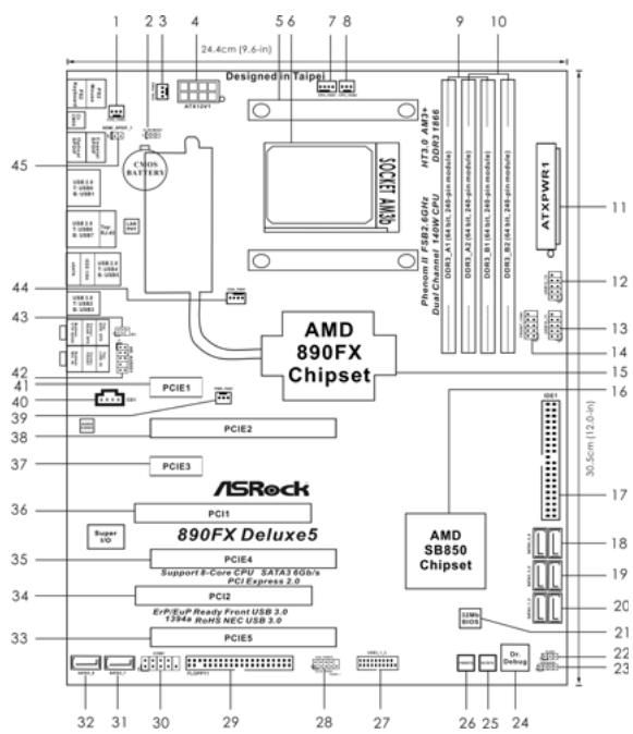
1 Chassis Fan Connector (CHA_FAN3)
2 Clear CMOS Jumper (CLRCMOS1)
3 Chassis Fan Connector (CHA_FAN2)
4 ATX 12V Power Connector (ATX12V1)
5 CPU Heatsink Retention Module
6 AM3+CPU Socket
7 CPU Fan Connector (CPU_FAN1)
8 CPU Fan Connector (CPU_FAN2)
9 2x240-pin DDR3 DIMM Slots
Dual Channel A: DDR3_A1, DDR3_B1; Blue)
10 2x240-pin DDR3 DIMM Slots
Dual Channel B: DDR3_A2, DDR3_B2; White)
11 ATX Power Connector (ATXPWR1)
12 USB 2.0 Header (USB12_13, Blue)
13 USB 2.0 Header (USB10_11, Blue)
14 Front Panel IEEE 1394 Header
(FRONT_1394, White)
15 Northbridge Controller
16 Southbridge Controller
17 Primary IDE Connector (IDE1, Blue)
18 SATA3 Connector (SATA3_5_6, White)
19 SATA3 Connector (SATA3_3_4, White)
20 SATA3 Connector (SATA3_1_2, White)
21 SPI Flash Memory (32Mb)
22 Power LED Header (PLED1)
23 Chassis Speaker Header
(SPEAKER 1, White)
24 Dr. Debug (LED)
25 Reset Switch (RSTBTN)
26 Power Switch (PWRBTN)
27 USB 3.0 Header (USB3_1_2, Light Blue)
28 System Panel Header (PANEL1, White)
29 Floppy Connector (FLOPPY1)
30 Serial Port Connector (COM1)
31 SATA3 Connector (SATA3_7, White)
32 SATA3 Connector (SATA3_8, White)
33 PCI Express 2.0 x16 Slot (PCIE5; Blue)
34 PCI Slot (PCI2)
35 PCI Express 2.0 x16 Slot (PCIE4; Blue)
36 PCI Slot (PCI1)
37 PCI Express 2.0 x1 Slot (PCIE3; White)
38 PCI Express 2.0 x16 Slot (PCIE2; Blue)
39 Power Fan Connector (PWR_FAN1)
40 Internal Audio Connector: CD1 (White)
41 PCI Express 2.0 x1 Slot (PCIE1; White)
42 Front Panel Audio Header
(HD_AUDIO1, White)
43 Infrared Module Header (IR1)
44 Chassis Fan Connector (CHA_FAN1)
45 HDMI_SPDIF Header (HDMI_SPDIF1,White)
I/O Panel
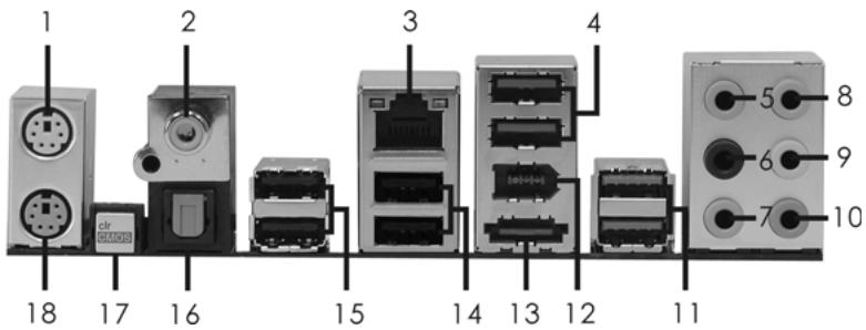
1 PS/2 Mouse Port (Green)
2 Coaxial SPDIF Out Port
3 LAN RJ-45 Port
4 USB 2.0 Ports (USB45)
5 Side Speaker (Gray)
6 Rear Speaker (Black)
7 Central/Bass (Orange)
8 Line In (Light Blue)
**9 Front Speaker (Lime)
10 Microphone (Pink)
11 USB 3.0 Ports (USB23)
12 IEEE 1394 Port (IEEE 1394)
13 eSATA3 Connector
14 USB 2.0 Ports (USB67)
15 USB 2.0 Ports (USB01)
16 Optical SPDIF Out Port
17 Clear CMOS Switch (CLRCBTN)
18 PS/2 Keyboard Port (Purple)
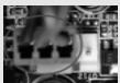
- There are two LED next to the LAN port. Please refer to the table below for the LAN port LED indications.
LAN Port LED Indications
Activity/Link LED
| Status | Description |
| Off | No Link |
| Blinking | Data Activity |
| On | Link |
SPEED LED
| Status | Description |
| Off | 10Mbps connection |
| Orange | 100Mbps connection |
| Green | 1Gbps connection |
ACT/LINK SPEED
LED LED
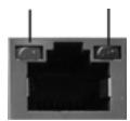
LAN Port
** If you use 2-channel speaker, please connect the speaker's plug into "Front Speaker Jack". See the table below for connection details in accordance with the type of speaker you use.
TABLE for Audio Output Connection
| Audio Output Channels | Front Speaker (No. 9) | Rear Speaker (No. 6) | Central / Bass (No. 7) | Side Speaker (No. 5) |
| 2 | V | -- | -- | -- |
| 4 | V | V | -- | -- |
| 6 | V | V | V | -- |
| 8 | V | V | V | V |
To enable Multi-Streaming function, you need to connect a front panel audio cable to the front panel audio header. After restarting your computer, you will find "Mixer" tool on your system. Please select "Mixer ToolBox", click "Enable playback multi-streaming", and click
"ok". Choose "2CH", "4CH", "6CH", or "8CH" and then you are allowed to select "Realtek HDA Primary output" to use Rear Speaker, Central/Bass, and Front Speaker, or select "Realtek HDA Audio 2nd output" to use front panel audio.
1. Introduction
Thank you for purchasing ASRock 890FX Deluxe5 motherboard, a reliable motherboard produced under ASRock's consistently stringent quality control. It delivers excellent performance with robust design conforming to ASRock's commitment to quality and endurance.
In this manual, chapter 1 and 2 contain introduction of the motherboard and step-by-step guide to the hardware installation. Chapter 3 and 4 contain the configuration guide to BIOS setup and information of the Support CD.

Because the motherboard specifications and the BIOS software might be updated, the content of this manual will be subject to change without notice. In case any modifications of this manual occur, the updated version will be available on ASRock website without further notice. You may find the latest VGA cards and CPU support lists on ASRock website as well. ASRock website http://www.asrock.com If you require technical support related to this motherboard, please visit our website for specific information about the model you are using. www.asrock.com/support/index.asp
1.1 Package Contents
ASRock 890FX Deluxe5 Motherboard
(ATX Form Factor: 12.0-in x 9.6-in, 30.5 cm x 24.4 cm)
ASRock 890FX Deluxe5 Quick Installation Guide
ASRock 890FX Deluxe5 Support CD
1 x Ultra ATA 66/100/133 IDE Ribbon Cable (80-conductor)
1 x Ribbon Cable for a 3.5-in Floppy Drive
4 x Serial ATA (SATA) Data Cables (Optional)
2 x Serial ATA (SATA) HDD Power Cables (Optional)
1 x I/O Panel Shield
1 x Front USB 3.0 Panel
4 x HDD Screws
6 x Chassis Screws
1 x Rear USB 3.0 Bracket
1.2 Specifications
| Platform | - ATX Form Factor: 12.0-in x 9.6-in, 30.5 cm x 24.4 cm - All Solid Capacitor design (100% Japan-made high-quality Conductive Polymer Capacitors) |
| CPU | - Support for Socket AM3+ processors - Support for Socket AM3 processors: AMD Phenom™ II X6 / X4 / X3 / X2 (except 920 / 940) / Athlon II X4 / X3 / X2 / Sempron processors - Supports 8-Core CPU - Supports UCC feature (Unlock CPU Core) (see CAUTION 1) - Advanced V8 + 2 Power Phase Design - Supports CPU up to 140W - Supports AMD's Cool 'n' Quiet™ Technology - FSB 2600 MHz (5.2 GT/s) - Supports Untied Overclocking Technology (see CAUTION 2) - Supports Hyper-Transport 3.0 (HT 3.0) Technology |
| Chipset | - Northbridge: AMD 890FX - Southbridge: AMD SB850 - AMD Vision Black |
| Memory | - Dual Channel DDR3 Memory Technology (see CAUTION 3) - 4 x DDR3 DIMM slots - Support DDR3 1866(OC)/1800(OC)/1600(OC)/1333/1066/800 non-ECC, un-buffered memory (see CAUTION 4) - Max. capacity of system memory: 32GB (see CAUTION 5) |
| Expansion Slot | - 3 x PCI Express 2.0 x16 slot (PCIE2/PCIE4 @ x16 mode; PCIE5 @ x4 mode) - 2 x PCI Express 2.0 x1 slots - 2 x PCI slots - Supports ATI™ Quad CrossFire™, 3-Way CrossFire™ and CrossFire™ |
| Audio | - 7.1 CH HD Audio with Content Protection (Realtek ALC892 Audio Codec) - Premium Blu-ray audio support - Supports THX TruStudio Pro™ |
| LAN | - PCIe x1 Gigabit LAN 10/100/1000 Mb/s - Realtek RTL8111E - Supports Wake-On-LAN - Supports LAN Cable Detection - Supports Energy Efficient Ethernet 802.3az |
| Rear Panel I/O | I/O Panel - 1 x PS/2 Mouse Port - 1 x PS/2 Keyboard Port - 1 x Coaxial SPDIF Out Port - 1 x Optical SPDIF Out Port - 6 x Ready-to-Use USB 2.0 Ports - 2 x Ready-to-Use USB 3.0 Ports - 1 x eSATA3 Connector - 1 x RJ-45 LAN Port with LED (ACT/LINK LED and SPEED LED) - 1 x IEEE 1394 Port - 1 x Clear CMOS Switch with LED - HD Audio Jack: Side Speaker/Rear Speaker/Central/Bass/Line in/ Front Speaker/Microphone (see CAUTION 6) |
| SATA3 | - 6 x SATA3 6.0 Gb/s connectors by AMD SB850, support RAID (RAID 0, RAID 1, RAID 0+1 and RAID 5), NCQ, AHCI and "Hot Plug" functions - 2 x SATA3 6.0 Gb/s connectors by Marvell SE9120, support NCQ, AHCI and "Hot Plug" functions |
| USB 3.0 | - 2 x Rear USB 3.0 ports by NEC UPD720200, support USB 1.0/2.0/3.0 up to 5Gb/s - 1 x Front USB 3.0 header (supports 2 USB 3.0 ports) by NEC UPD720200, supports USB 1.0/2.0/3.0 up to 5Gb/s |
| Connector | - 8 x SATA3 6.0Gb/s connectors - 1 x ATA133 IDE connector (supports 2 x IDE devices) - 1 x Floppy connector - 1 x IR header - 1 x COM port header - 1 x IEEE 1394 header - 1 x HDMI_SPDIF header - 1 x Power LED header - CPU/Chassis/Power FAN connector - 24 pin ATX power connector - 8 pin 12V power connector - CD in header - Front panel audio connector - 2 x USB 2.0 headers (support 4 USB 2.0 ports) - 1 x USB 3.0 header (supports 2 USB 3.0 ports) - 1 x Dr. Debug (7-Segment Debug LED) |
| Smart Switch | - 1 x Clear CMOS Switch with LED - 1 x Power Switch with LED - 1 x Reset Switch with LED |
| BIOS Feature | - 32Mb AMI UEFI Legal BIOS with GUI support - Supports “Plug and Play” - ACPI 1.1 Compliance Wake Up Events - Supports jumperfree - SMBIOS 2.3.1 Support - CPU, VCCM, NB, SB Voltage Multi-adjustment |
| Support CD | - Drivers, Utilities, AntiVirus Software (Trial Version), AMD OverDrive™ Utility, ASRock Software Suite (CyberLink DVD Suite - OEM and Trial) |
| Unique Feature | - ASRock Extreme Tuning Utility (AXTU) (see CAUTION 7) - Instant Boot - ASRock Instant Flash (see CAUTION 8) - ASRock AIWI (see CAUTION 9) - ASRock APP Charger (see CAUTION 10) - SmartView (see CAUTION 11) - ASRock XFast USB (see CAUTION 12) - Hybrid Booster: - CPU Frequency Stepless Control (see CAUTION 13) - ASRock U-COP (see CAUTION 14) - Boot Failure Guard (B.F.G.) - Turbo 50 / Turbo 60 CPU Overclocking - Turbo UCC |
| Hardware Monitor | - CPU Temperature Sensing - Chassis Temperature Sensing - CPU/Chassis/Power Fan Tachometer - CPU Quiet Fan - CPU/Chassis Fan Multi-Speed Control - Voltage Monitoring: +12V, +5V, +3.3V, Vcore |
| OS | - Microsoft® Windows® 7 / 7 64-bit / Vista™ / Vista™ 64-bit / XP / XP 64-bit compliant |
| Certifications | - FCC, CE, WHQL - ErP/EuP Ready (ErP/EuP ready power supply is required) (see CAUTION 15) |
- For detailed product information, please visit our website: http://www.asrock.com
WARNING
Please realize that there is a certain risk involved with overclocking, including adjusting the setting in the BIOS, applying Untied Overclocking Technology, or using the third-party overclocking tools. Overclocking may affect your system stability, or even cause damage to the components and devices of your system. It should be done at your own risk and expense. We are not responsible for possible damage caused by overclocking.
CAUTION!
- ASRock UCC (Unlock CPU Core) feature simplifies AMD CPU activation. As long as a simple switch of the UEFI option "ASRock UCC", you can unlock the extra CPU core to enjoy an instant performance boost. When UCC feature is enabled, the dual-core or triple-core CPU will boost to the quad-core CPU, and some CPU, including quad-core CPU, can also increase L3 cache size up to 6MB, which means you can enjoy the upgrade CPU performance with a better price. Please be noted that UCC feature is supported with AM3/AM3+ CPU only, and in addition, not every AM3/AM3+ CPU can support this function because some CPU's hidden core may be malfunctioned.
- This motherboard supports Untied Overclocking Technology. Please read "Untied Overclocking Technology" on page 36 for details.
- This motherboard supports Dual Channel Memory Technology. Before you implement Dual Channel Memory Technology, make sure to read the installation guide of memory modules on page 13 for proper installation.
- Whether 1866/1800/1600MHz memory speed is supported depends on the AM3/AM3+ CPU you adopt. If you want to adopt DDR3 1866/1800/1600 memory module on this motherboard, please refer to the memory support list on our website for the compatible memory modules. ASRock website http://www.asrock.com
- Due to the operating system limitation, the actual memory size may be less than 4GB for the reservation for system usage under Windows® 7 / Vista™ / XP. For Windows® OS with 64-bit CPU, there is no such limitation.
- For microphone input, this motherboard supports both stereo and mono modes. For audio output, this motherboard supports 2-channel, 4-channel, 6-channel, and 8-channel modes. Please check the table on page 3 for proper connection.
-
ASRock Extreme Tuning Utility (AXTU) is an all-in-one tool to ne-tune different system functions in a user-friendly interface, which is including Hardware Monitor, Fan Control, Overclocking, OC DNA and IES. In Hardware Monitor, it shows the major readings of your system. In Fan Control, it shows the fan speed and temperature for you to adjust. In Overclocking, you are allowed to overclock CPU frequency for optimal system performance. In OC DNA, you can save your OC settings as a profile and share with your friends. Your friends then can load the OC profile to their own system to get the same OC settings. In IES (Intelligent Energy Saver), the voltage regulator can reduce the number of output phases to improve efficiency when the CPU cores are idle without sacrificing computing performance. Please visit our website for the operation procedures of ASRock Extreme Tuning Utility (AXTU). ASRock website: http://www.asrock.com
-
ASRock Instant Flash is a BIOS flash utility embedded in Flash ROM. This convenient BIOS update tool allows you to update system BIOS without entering operating systems first like MS-DOS or Windows®. With this utility, you can press <F6> key during the POST or press <F2> key to BIOS setup menu to access ASRock Instant Flash. Just launch this tool and save the new BIOS file to your USB flash drive, floppy disk or hard drive, then you can update your BIOS only in a few clicks without preparing an additional floppy diskette or other complicated flash utility. Please be noted that the USB flash drive or hard drive must use FAT32/16/12 file system.
-
To experience intuitive motion controlled games is no longer only available at Wii. ASRock AIWI utility introduces a new way of PC gaming operation. ASRock AIWI is the world's first utility to turn your iPhone/iPod touch as a game joystick to control your PC games. All you have to do is just to install the ASRock AIWI utility either from ASRock official website or ASRock software support CD to your motherboard, and also download the free AIWI Lite from App store to your iPhone/iPod touch. Connecting your PC and apple devices via Bluetooth or WiFi networks, then you can start experiencing the exciting motion controlled games. Also, please do not forget to pay attention to ASRock official website regularly, we will continuously provide you the most up-do-date supported games! ASRock website: http://www.asrock.com/Feature/Aiwi/index.asp
-
If you desire a faster, less restricted way of charging your Apple devices, such as iPhone/iPod/iPad Touch, ASRock has prepared a wonderful solution for you - ASRock APP Charger. Simply installing the APP Charger driver, it makes your iPhone charged much quickly from your computer and up to 40% faster than before. ASRock APP Charger allows you to quickly charge many Apple devices simultaneously and even supports continuous charging when your PC enters into Standby mode (S1), Suspend to RAM (S3), hibernation mode (S4) or power off (S5). With APP Charger driver installed, you can easily enjoy the marvelous charging experience than ever.
ASRock website: http://www.asrock.com/Feature/AppCharger/index.asp
- SmartView, a new function of internet browser, is the smart start page for IE that combines your most visited web sites, your history, your Facebook friends and your real-time newsfeed into an enhanced view for a more personal Internet experience. ASRock motherboards are exclusively equipped with the SmartView utility that helps you keep in touch with friends on-the-go. To use SmartView feature, please make sure your OS version is Windows® 7 / 7 64 bit / Vista™ / Vista™ 64 bit, and your browser version is IE8.
ASRock website: http://www.asrock.com/Feature/SmartView/index.asp
-
ASRock XFast USB can boost USB storage device performance. The performance may depend on the property of the device.
-
Although this motherboard offers stepless control, it is not recommended to perform over-clocking. Frequencies other than the recommended CPU bus frequencies may cause the instability of the system or damage the CPU.
- While CPU overheat is detected, the system will automatically shutdown. Before you resume the system, please check if the CPU fan on the motherboard functions properly and unplug the power cord, then plug it back again. To improve heat dissipation, remember to spray thermal grease between the CPU and the heatsink when you install the PC system.
- EuP, stands for Energy Using Product, was a provision regulated by European Union to define the power consumption for the completed system. According to EuP, the total AC power of the completed system shall be under 1.00W in off mode condition. To meet EuP standard, an EuP ready motherboard and an EuP ready power supply are required. According to Intel's suggestion, the EuP ready power supply must meet the standard of 5v standby power efficiency is higher than 50% under 100mA current consumption. For EuP ready power supply selection, we recommend you checking with the power supply manufacturer for more details.
2. Installation
This is an ATX form factor (12.0-in x 9.6-in, 30.5 cm x 24.4 cm) motherboard.
Before you install the motherboard, study the configuration of your chassis to ensure that the motherboard fits into it.
Pre-Installation Precautions
Take note of the following precautions before you install motherboard components or change any motherboard settings.

Before you install or remove any component, ensure that the power is switched off or the power cord is detached from the power supply. Failure to do so may cause severe damage to the motherboard, peripherals, and/or components.
- Unplug the power cord from the wall socket before touching any component.
- To avoid damaging the motherboard components due to static electricity, NEVER place your motherboard directly on the carpet or the like. Also remember to use a grounded wrist strap or touch a safety grounded object before you handle components.
- Hold components by the edges and do not touch the ICs.
- Whenever you uninstall any component, place it on a grounded anti-static pad or in the bag that comes with the component.
- When placing screws into the screw holes to secure the motherboard to the chassis, please do not over-tighten the screws! Doing so may damage the motherboard.
2.1 CPU Installation
Step 1. Unlock the socket by lifting the lever up to a 90^ angle.
Step 2. Position the CPU directly above the socket such that the CPU corner with the golden triangle matches the socket corner with a small triangle.
Step 3. Carefully insert the CPU into the socket until it fits in place.

The CPU fits only in one correct orientation. DO NOT force the CPU into the socket to avoid bending of the pins.
Step 4. When the CPU is in place, press it firmly on the socket while you push down the socket lever to secure the CPU. The lever clicks on the side tab to indicate that it is locked.
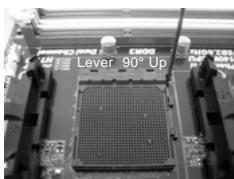
STEP1:
Lift Up The Socket Lever
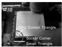
STEP 2/STEP3:
Match The CPU Golden Triangle
To The Socket Corner Small
Triangle
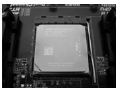
STEP4:
Push Down And Lock
The Socket Lever
2.2 Installation of CPU Fan and Heatsink
After you install the CPU into this motherboard, it is necessary to install a larger heatsink and cooling fan to dissipate heat. You also need to spray thermal grease between the CPU and the heatsink to improve heat dissipation. Make sure that the CPU and the heatsink are securely fastened and in good contact with each other. Then connect the CPU fan to the CPU FAN connector (CPU_FAN1, see Page 2, No. 7 or CPU_FAN2, see Page 2, No. 8). For proper installation, please kindly refer to the instruction manuals of the CPU fan and the heatsink.
2.3 Installation of Memory Modules (DIMM)
This motherboard provides four 240-pin DDR3 (Double Data Rate 3) DIMM slots, and supports Dual Channel Memory Technology. For dual channel configuration, you always need to install identical (the same brand, speed, size and chip-type) DDR3 DIMM pair in the slots of the same color. In other words, you have to install identical DDR3 DIMM pair in Dual Channel A (DDR3_A1 and DDR3_B1; Blue slots; see p.2 No.9) or identical DDR3 DIMM pair in Dual Channel B (DDR3_A2 and DDR3_B2; White slots; see p.2 No.10), so that Dual Channel Memory Technology can be activated. This motherboard also allows you to install four DDR3 DIMMs for dual channel configuration, and please install identical DDR3 DIMMs in all four slots. You may refer to the Dual Channel Memory Configuration Table below.
Dual Channel Memory Configurations
| DDR3_A1 (Blue Slot) | DDR3_A2 (White Slot) | DDR3_B1 (Blue Slot) | DDR3_B2 (White Slot) | |
| (1) | Populated | - | Populated | - |
| (2) | - | Populated | - | Populated |
| (3)* | Populated | Populated | Populated | Populated |
- For the configuration (3), please install identical DDR3 DIMMs in all four slots.

- If you want to install two memory modules, for optimal compatibility and reliability, it is recommended to install them in the slots of the same color. In other words, install them either in the set of blue slots (DDR3_A1 and DDR3_B1), or in the set of white slots (DDR3_A2 and DDR3_B2).
- If only one memory module or three memory modules are installed in the DDR3 DIMM slots on this motherboard, it is unable to activate the Dual Channel Memory Technology.
- If a pair of memory modules is NOT installed in the same Dual Channel, for example, installing a pair of memory modules in DDR3_A1 and DDR3_A2, it is unable to activate the Dual Channel Memory Technology.
- It is not allowed to install a DDR or DDR2 memory module into DDR3 slot; otherwise, this motherboard and DIMM may be damaged.
- If you adopt DDR3 1866/1800/1600 memory modules on this motherboard, it is recommended to install them on DDR3_A2 and DDR3_B2 slots.
Installing a DIMM

Please make sure to disconnect power supply before adding or removing DIMMs or the system components.
Step 1. Unlock a DIMM slot by pressing the retaining clips outward.
Step 2. Align a DIMM on the slot such that the notch on the DIMM matches the break on the slot.
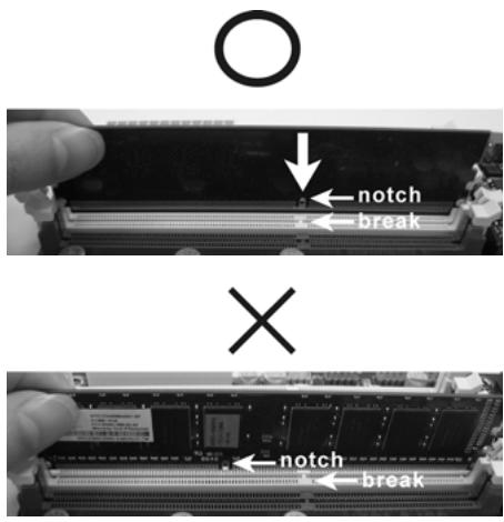

The DIMM only fits in one correct orientation. It will cause permanent damage to the motherboard and the DIMM if you force the DIMM into the slot at incorrect orientation.
Step 3. Firmly insert the DIMM into the slot until the retaining clips at both ends fully snap back in place and the DIMM is properly seated.
2.4 Expansion Slots (PCI and PCI Express Slots)
There are 2 PCI slots and 5 PCI Express slots on this motherboard.
PCI Slots: PCI slots are used to install expansion cards that have the 32-bit PCI interface.
PCIE Slots:
PCIE1 / PCIE3 (PCIE x1 slot; White) is used for PCI Express cards with x1 lane width cards, such as Gigabit LAN card and SATA2 card.
PCIE2 / PCIE4 (PCIE x16 slot; Blue) is used for PCI Express x16 lane width graphics cards, or used to install PCI Express graphics cards to support CrossFire™ function.
PCIE5 (PCIE x16 slot; Blue) is used for PCI Express x4 lane width cards, or used to install PCI Express graphics cards to support 3-Way CrossFireX™ function.

- In single VGA card mode, it is recommended to install a PCI Express x16 graphics card on PCIE2 slot.
- In CrossFireX™ mode, please install PCI Express x16 graphics cards on PCIE2 and PCIE4 slots.
- In 3-Way CrossFireX™ mode, please install PCI Express x16 graphics cards on PCIE2, PCIE4 and PCIE5 slots.
- Please connect a chassis fan to motherboard chassis fan connector (CHA_FAN1, CHA_FAN2 or CHA_FAN3) when using multiple graphics cards for better thermal environment.
Installing an expansion card
Step 1. Before installing the expansion card, please make sure that the power supply is switched off or the power cord is unplugged. Please read the documentation of the expansion card and make necessary hardware settings for the card before you start the installation.
Step 2. Remove the system unit cover (if your motherboard is already installed in a chassis).
Step 3. Remove the bracket facing the slot that you intend to use. Keep the screws for later use.
Step 4. Align the card connector with the slot and press firmly until the card is completely seated on the slot.
Step 5. Fasten the card to the chassis with screws.
Step 6. Replace the system cover.
2.5 CrossFireX™, 3-Way CrossFireX™ and Quad CrossFireX™ Operation Guide
This motherboard supports CrossFireX™, 3-way CrossFireX™ and Quad CrossFireX™ feature. CrossFireX™ technology offers the most advantageous means available of combining multiple high performance Graphics Processing Units (GPU) in a single PC. Combining a range of different operating modes with intelligent software design and an innovative interconnect mechanism, CrossFireX™ enables the highest possible level of performance and image quality in any 3D application. Currently CrossFireX™ feature is supported with Windows® XP with Service Pack 2 / Vista™ / 7 OS. 3-way CrossFireX™ and Quad CrossFireX™ feature are supported with Windows® Vista™ / 7 OS only. Please check AMD website for ATI™ CrossFireX™ driver updates.

- If a customer incorrectly configures their system they will not see the performance benefits of CrossFireX™. All three CrossFireX™ components, a CrossFireX™ Ready graphics card, a CrossFireX™ Ready motherboard and a CrossFireX™ Edition co-processor graphics card, must be installed correctly to benefit from the CrossFireX™ multi-GPU platform.
- If you pair a 12-pipe CrossFireX™ Edition card with a 16-pipe card, both cards will operate as 12-pipe cards while in CrossFireX™ mode.
2.5.1 Graphics Card Setup
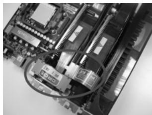
2.5.1.1 Installing Two CrossFireX™-Ready Graphics Cards

Different CrossFireX™ cards may require different methods to enable CrossFireX™ feature. In below procedures, we use Radeon HD 3870 as the example graphics card. For other CrossFireX™ cards that ATI™ has released or will release in the future, please refer to ATI™ graphics card manuals for detailed installation guide.
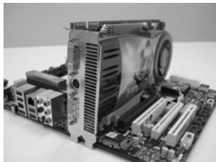
Step 1. Insert one Radeon graphics card into PCIE2 slot and the other Radeon graphics card to PCIE4 slot. Make sure that the cards are properly seated on the slots.
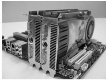
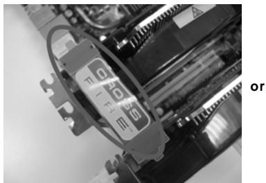
Step 2. Connect two Radeon graphics cards by installing CrossFire Bridge on CrossFire Bridge Interconnects on the top of Radeon graphics cards. (CrossFire Bridge is provided with the graphics card you purchase, not bundled with this motherboard. Please refer to your graphics card vendor for details.)
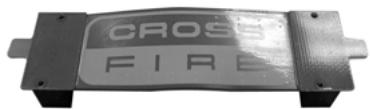
CrossFire Bridge
Step 3. Connect the DVI monitor cable to the DVI connector on the Radeon graphics card on PCIE2 slot. (You may use the DVI to D-Sub adapter to convert the DVI connector to D-Sub interface, and then connect the D-Sub monitor cable to the DVI to D-Sub adapter.)
2.5.1.2 Installing Three CrossFireX™-Ready Graphics Cards
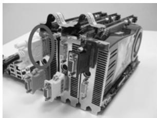
Step 1. Install one Radeon graphics card to PCIE2 slot. For the proper installation procedures, please refer to section "Expansion Slots".
Step 2. Install one Radeon graphics card to PCIE4 slot. For the proper installation procedures, please refer to section "Expansion Slots".
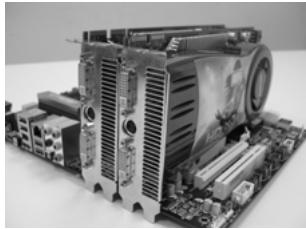
Step 3. Install one Radeon graphics card to PCIE5 slot. For the proper installation procedures, please refer to section "Expansion Slots".
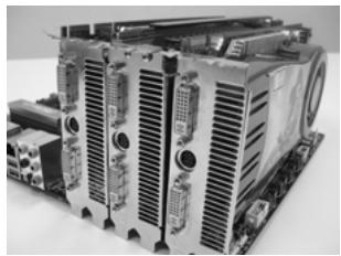
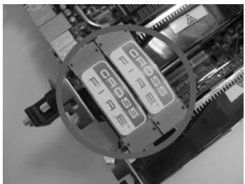
Step 4. Use one CrossFire™ Bridge to connect Radeon graphics cards on PCIE2 and PCIE4 slots, and use the other CrossFire™ Bridge to connect Radeon graphics cards on PCIE4 and PCIE5 slots. (CrossFire™ Bridge is provided with the graphics card you purchase, not bundled with this motherboard. Please refer to your graphics card vendor for details.)
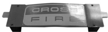
CrossFire™ Bridge
Step 5. Connect the DVI monitor cable to the DVI connector on the Radeon graphics card on PCIE2 slot. (You may use the DVI to D-Sub adapter to convert the DVI connector to D-Sub interface, and then connect the D-Sub monitor cable to the DVI to D-Sub adapter.)
2.5.2 Driver Installation and Setup
Step 1. Power on your computer and boot into OS.
Step 2. Remove the ATI^TM driver if you have any VGA driver installed in your system.

The Catalyst Uninstaller is an optional download. We recommend using this utility to uninstall any previously installed Catalyst drivers prior to installation. Please check AMD website for ATI™ driver updates.
Step 3. Install the required drivers to your system.
For Windows XP OS:
A. ATI™ recommends Windows® XP Service Pack 2 or higher to be installed (If you have Windows® XP Service Pack 2 or higher installed in your system, there is no need to download it again): http://www.microsoft.com/windowsxp/sp2/default.mspx
B. You must have Microsoft .NET Framework installed prior to downloading and installing the CATALYST Control Center. Please check Microsoft website for details.
For Windows® 7 / Vista™ OS:
Install the CATALYST Control Center. Please check AMD website for details.
Step 4. Restart your computer.
Step 5. Install the VGA card drivers to your system, and restart your computer. Then you will find "ATI Catalyst Control Center" on your Windows® taskbar.
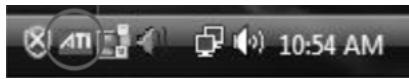
ATI Catalyst Control Center
Step 6. Double-click "ATI Catalyst Control Center". Click "View", select "CrossFireX™", and then check the item "Enable CrossFireX™". Select "2 GPUs" and click "Apply" (if you install two Radeon graphics cards). Select "3 GPUs" and click "OK" (if you install three Radeon graphics cards).
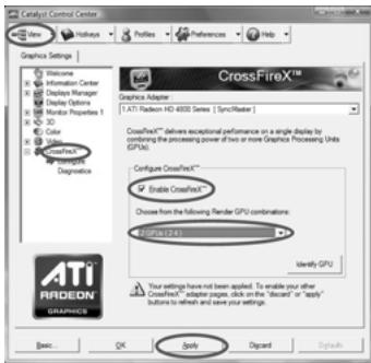

Although you have selected the option "Enable CrossFire™", the CrossFireX™ function may not work actually. Your computer will automatically reboot. After restarting your computer, please confirm whether the option "Enable CrossFire™" in "ATI Catalyst Control Center" is selected or not; if not, please select it again, and then you are able to enjoy the benefit of CrossFireX™ feature.
Step 7. You can freely enjoy the benefit of CrossFireX™, 3-Way CrossFireX™ or Quad CrossFireX™ feature.
- CrossFire™ appearing here is a registered trademark of ATI™ Technologies Inc., and is used only for identification or explanation and to the owners' benefit, without intent to infringe.
- For further information of ATI™ CrossFireX™ technology, please check AMD website for updates and details.
2.6 Surround Display Feature
This motherboard supports Surround Display upgrade. With the external add-on PCI Express VGA cards, you can easily enjoy the benefits of Surround Display feature. For the detailed instruction, please refer to the document at the following path in the Support CD:
Surround Display Information
2.7 Jumpers Setup
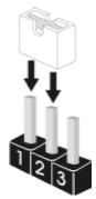
The illustration shows how jumpers are setup. When the jumper cap is placed on pins, the jumper is "Short". If no jumper cap is placed on pins, the jumper is "Open". The illustration shows a 3-pin jumper whose pin1 and pin2 are "Short" when jumper cap is placed on these 2 pins.
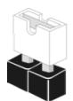
Short

Open
Jumper Setting
Clear CMOS Jumper
(CLRCMOS1)
(see p.2, No. 2)


Default

Clear CMOS
Note: CLRCMOS1 allows you to clear the data in CMOS. The data in CMOS includes system setup information such as system password, date, time, and system setup parameters. To clear and reset the system parameters to default setup, please turn off the computer and unplug the power cord from the power supply. After waiting for 15 seconds, use a jumper cap to short pin2 and pin3 on CLRCMOS1 for 5 seconds. However, please do not clear the CMOS right after you update the BIOS. If you need to clear the CMOS when you just finish updating the BIOS, you must boot up the system first, and then shut it down before you do the clear-CMOS action.
2.8 Onboard Headers and Connectors

Onboard headers and connectors are NOT jumpers. Do NOT place jumper caps over these headers and connectors. Placing jumper caps over the headers and connectors will cause permanent damage of the motherboard!
FDD connector
(33-pin FLOPPY1)
(see p.2 No. 29)
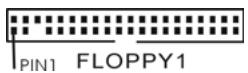
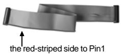
Note: Make sure the red-striped side of the cable is plugged into Pin1 side of the connector.
Primary IDE connector (Blue)
(39-pin IDE1, see p.2 No. 17)
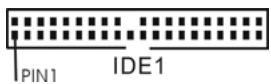
connect the blue end to the motherboard
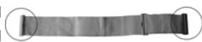
connect the black end to the IDE devices
80-conductor ATA 66/100/133 cable
Note: Please refer to the instruction of your IDE device vendor for the details.
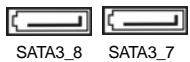
Serial ATA3 Connectors
(SATA3_1_2: see p.2, No. 20)
(SATA3_3_4: see p.2, No.19)
(SATA3_5_6.see p.2,No.18)
(SATA3_7: see p.2, No. 31)
(SATA3_8: see p.2, No. 32)
5 5
These eight Serial ATA3 (SATA3) connectors support SATA data cables for internal storage devices. The current SATA3 interface allows up to 6.0 Gb/s data transfer rate. If you install the HDD on the eSATA port on the rear I/O, the internal SATA3_8 will not function.
Serial ATA (SATA)
Data Cable
(Optional)
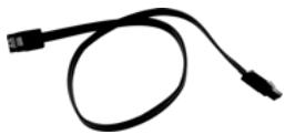
Either end of the SATA data cable can be connected to the SATA3 hard disk or the SATA3 connector on this motherboard.
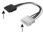
Serial ATA (SATA)
Power Cable
(Optional)
connect to the SATA HDD power connector
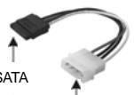
connect to the power supply
Please connect the black end of SATA power cable to the power connector on each drive. Then connect the white end of SATA power cable to the power connector of the power supply.
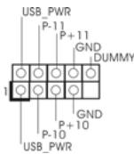
USB 2.0 Headers
(9-pin USB10_11)
(see p.2 No.13)
(9-pin USB12_13)
(see p.2 No. 12)
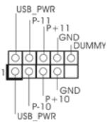
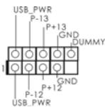
Besides six default USB 2.0 ports on the I/O panel, there are two USB 2.0 headers on this motherboard. Each USB 2.0 header can support two USB 2.0 ports.
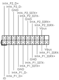
USB 3.0 Header
(19-pin USB3_1_2)
(see p.2 No. 27)
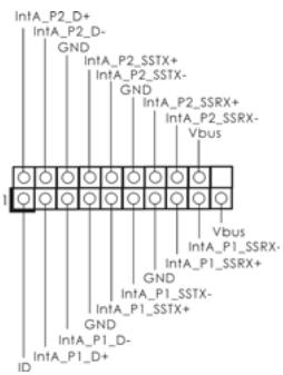
Besides two default USB 3.0 ports on the I/O panel, there is one USB 3.0 header on this motherboard. This USB 3.0 header can support two USB 3.0 ports.
Infrared Module Header
(5-pin IR1)
(see p.2 No. 43)
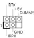
This header supports an optional wireless transmitting and receiving infrared module.
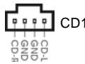
Internal Audio Connectors
(4-pin CD1)
(CD1: see p.2 No. 40)

CD1
This connector allows you to receive stereo audio input from sound sources such as a CD-ROM, DVD-ROM, TV tuner card, or MPEG card.
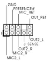
Front Panel Audio Header
(9-pin HD AUDIO1)
(see p.2, No.42)
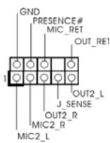
This is an interface for the front panel audio cable that allows convenient connection and control of audio devices.

- High Definition Audio supports Jack Sensing, but the panel wire on the chassis must support HDA to function correctly. Please follow the instruction in our manual and chassis manual to install your system.
- If you use AC'97 audio panel, please install it to the front panel audio header as below:
A. Connect Mic_IN (MIC) to MIC2_L.
B. Connect Audio_R (RIN) to OUT2_R and Audio_L (LIN) to OUT2_L.
C. Connect Ground (GND) to Ground (GND).
D. MIC_RET and OUT_RET are for HD audio panel only. You don't need to connect them for AC'97 audio panel.
E. To activate the front mic.
For Windows XP / XP 64-bit OS:
Select "Mixer". Select "Recorder". Then click "FrontMic".
For Windows® 7 / 7 64-bit / Vista™ / Vista™ 64-bit OS:
Go to the "FrontMic" Tab in the Realtek Control panel. Adjust
"Recording Volume".
System Panel Header
(9-pin PANEL1)
(see p.2 No. 28)
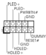
This header accommodates several system front panel functions.

Connect the power switch, reset switch and system status indicator on the chassis to this header according to the pin assignments below. Note the positive and negative pins before connecting the cables.
PWRBTN (Power Switch):
Connect to the power switch on the chassis front panel. You may configure the way to turn off your system using the power switch.
RESET (Reset Switch):
Connect to the reset switch on the chassis front panel. Press the reset switch to restart the computer if the computer freezes and fails to perform a normal restart.
PLED (System Power LED):
Connect to the power status indicator on the chassis front panel. The LED is on when the system is operating. The LED keeps blinking when the sys-tem is in S1 sleep state. The LED is off when the system is in S3/S4 sleep state or powered off (S5).
HDLED (Hard Drive Activity LED):
Connect to the hard drive activity LED on the chassis front panel. The LED is on when the hard drive is reading or writing data.
The front panel design may differ by chassis. A front panel module mainly consists of power switch, reset switch, power LED, hard drive activity LED, speaker and etc. When connecting your chassis front panel module to this header, make sure the wire assignments and the pin assignments are matched correctly.
Power LED Header
(3-pin PLED1)
(see p.2 No. 22)

Please connect the chassis power LED to this header to indicate system power status. The LED is on when the system is operating. The LED keeps blinking in S1 state. The LED is off in S3/S4 state or S5 state (power off).
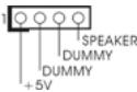
Chassis Speaker Header
(4-pin SPEAKER 1)
(see p.2 No. 23)
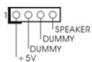
Please connect the chassis speaker to this header.
Chassis and Power Fan Connectors
(4-pin CHA_FAN1)
(see p.2 No. 44)
(3-pin CHA_FAN2)
(see p.2 No. 3)
(3-pin CHA_FAN3)
(see p.2 No.1)
(3-pin PWR_FAN1)
(see p.2 No. 39)


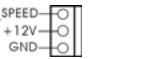
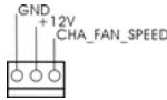
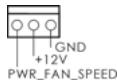
Please connect the fan cables to the fan connectors and match the black wire to the ground pin. CHA_FAN1/2/3 fan speed can be controlled through BIOS or OC Tuner utility.
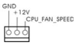
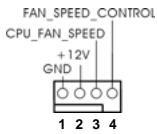
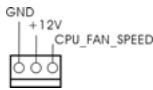
CPU Fan Connectors
(4-pin CPU_FAN1)
(see p.2 No.7)
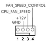
Please connect the CPU fan cable to the connector and match the black wire to the ground pin.

Though this motherboard provides 4-Pin CPU fan (Quiet Fan) support, the 3-Pin CPU fan still can work successfully even without the fan speed control function. If you plan to connect the 3-Pin CPU fan to the CPU fan connector on this motherboard, please connect it to Pin 1-3.
Pin 1-3 Connected
3-Pin Fan Installation
(3-pin CPU_FAN2)
(see p.2 No.8)
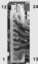
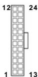
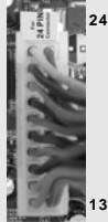
ATX Power Connector
(24-pinATXPWR1)
(see p.2 No. 11)
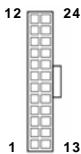

Though this motherboard provides 24-pin ATX power connector, it can still work if you adopt a traditional 20-pin ATX power supply. To use the 20-pin ATX power supply, please plug your power supply along with Pin 1 and Pin 13.
Please connect an ATX power supply to this connector.
20-PinATX Power Supply Installation
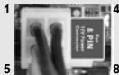
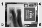
ATX 12V Power Connector
(8-pinATX12V1)
(see p.2 No. 4)

Please connect an ATX 12V
power supply to this connector.

Though this motherboard provides 8-pin ATX 12V power connector, it can still work if you adopt a traditional 4-pin ATX 12V power supply. To use the 4-pin ATX power supply, please plug your power supply along with Pin 1 and Pin 5.
4-PinATX12VPower Supply Installation
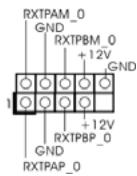
IEEE 1394 Header
(9-pin FRONT_1394)
(see p.2 No. 14)
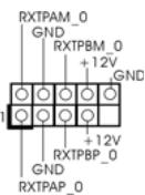
Besides one default IEEE 1394 port on the I/O panel, there is one IEEE 1394 header
(FRONT_1394) on this motherboard. This IEEE 1394 header can support one IEEE 1394 port.
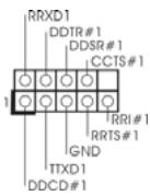
Serial port Header
(9-pin COM1)
(see p.2 No.30)
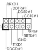
This COM1 header supports a serial port module.
HDMI_SPDIFHeader
(2-pin HDMI_SPDIF1)
(see p.2 No. 45)

SPDIFOUT
HDMI_SPDIF header, providing SPDIF audio output to HDMI VGA card, allows the system to connect HDMI Digital TV/ projector/LCD devices. Please connect the HDMI_SPDIF connector of HDMI VGA card to this header.
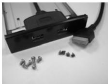
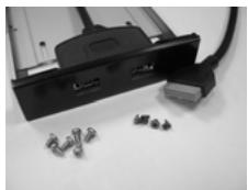
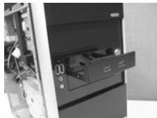
Front USB 3.0 Panel Installation Guide
Step 1
Prepare the bundled Front USB 3.0 Panel, four HDD screws, and six chassis screws.
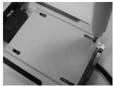
Step 2
Screw the 2.5" HDD/SSD to the Front USB 3.0 Panel with four HDD screws.
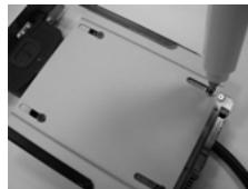
Step 3
Intall the Front USB 3.0 Panel into the 2.5" drive bay of the chassis.
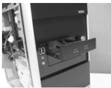
Step 4
Screw the Front USB 3.0 Panel to the drive bay with six chassis screws.
Step 5
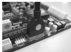
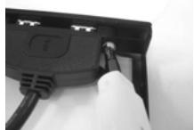
Plug the Front USB 3.0 cable into the USB 3.0 header (USB3_1_2) on the motherboard.
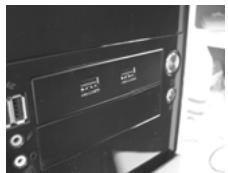
Step 6
The Front USB 3.0 Panel is ready to use.
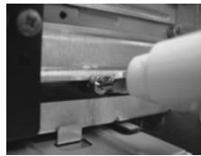
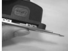
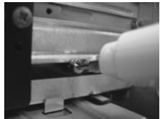
Rear USB 3.0 Bracket Installation Guide
Step 1 Unscrew the two screws from the Front USB 3.0 Panel.
Step 2 Put the USB 3.0 cable and the rear USB 3.0 bracket together.
Step 3 Screw the two screws into the rear USB 3.0 bracket.
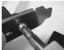
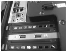
Step 4 Put the rear USB 3.0 bracket into the chassis.
2.9 Smart Switches
This motherboard has three smart switches: power switch, reset switch and clear CMOS switch, allowing users to quickly turn on/off or reset the system or clear the CMOS values.
Power Switch
(PWRBTN)
(see p.2 No. 26)

Power Switch is a smart switch, allowing users to quickly turn on/off the system.
Reset Switch
(RSTBTN)
(see p.2 No. 25)

Reset Switch is a smart switch, allowing users to quickly reset the system.
Clear CMOS Switch
(CLRCBTN)
(see p.3 No.17)

Clear CMOS Switch is a smart switch, allowing users to quickly clear the CMOS values

You are not allowed to use Clear CMOS switch function if you set up the system password. If you want to clear the CMOS values, please clean your system password in advance or refer to page 22 "Clear CMOS jumper" description instead.
2.10 Dr. Debug
Dr. Debug is used to provide code information, which makes troubleshooting even easier. Please see the diagrams below for reading the Dr. Debug codes.
| Status Code | Description |
| 0x00 | Not used |
| 0x01 | Power on. Reset type detection (soft/hard) |
| 0x02 | AP initialization before microcode loading |
| 0x03 | North Bridge initialization before microcode loading |
| 0x04 | South Bridge initialization before microcode loading |
| 0x05 | OEM initialization before microcode loading |
| 0x06 | Microcode loading |
| 0x07 | AP initialization after microcode loading |
| 0x08 | North Bridge initialization after microcode loading |
| 0x09 | South Bridge initialization after microcode loading |
| 0x0A | OEM initialization after microcode loading |
| 0x0B | Cache initialization |
| 0x0C - 0x0D | Reserved for future AMI SEC error codes |
| 0x0E | Microcode not found |
| 0x0F | Microcode not loaded |
| 0x10 | PEI Core is started |
| 0x11 | Pre-memory CPU initialization is started |
| 0x12 | Pre-memory CPU initialization (CPU module specific) |
| 0x13 | Pre-memory CPU initialization (CPU module specific) |
| 0x14 | Pre-memory CPU initialization (CPU module specific) |
| 0x15 | Pre-memory North Bridge initialization is started |
| 0x16 | Pre-Memory North Bridge initialization (North Bridge module specific) |
| 0x17 | Pre-Memory North Bridge initialization (North Bridge module specific) |
| 0x18 | Pre-Memory North Bridge initialization (North Bridge module specific) |
| 0x19 | Pre-memory South Bridge initialization is started |
| 0x1A | Pre-memory South Bridge initialization (South Bridge module specific) |
| 0x1B | Pre-memory South Bridge initialization (South Bridge module specific) |
| 0x1C | Pre-memory South Bridge initialization (South Bridge module specific) |
| 0x1D - 0x2A | OEM pre-memory initialization codes |
| 0x2B | Memory initialization. Serial Presence Detect (SPD) data reading |
| 0x2C | Memory initialization. Memory presence detection |
| 0x2D | Memory initialization. Programming memory timing information |
| 0x2E | Memory initialization. Configuring memory |
| 0x2F | Memory initialization (other) |
| 0x30 | Reserved for ASL (see ASL Status Codes section below) |
| 0x31 | Memory Installed |
| 0x32 | CPU post-memory initialization is started |
| 0x33 | CPU post-memory initialization. Cache initialization |
| 0x34 | CPU post-memory initialization. Application Processor(s) (AP) initialization |
| 0x35 | CPU post-memory initialization. Boot Strap Processor (BSP) selection |
| 0x36 | CPU post-memory initialization. System Management Mode (SMM) initialization |
| 0x37 | Post-Memory North Bridge initialization is started |
| 0x38 | Post-Memory North Bridge initialization (North Bridge module specific) |
| 0x39 | Post-Memory North Bridge initialization (North Bridge module specific) |
| 0x3A | Post-Memory North Bridge initialization (North Bridge module specific) |
| 0x3B | Post-Memory South Bridge initialization is started |
| 0x3C | Post-Memory South Bridge initialization (South Bridge module specific) |
| 0x3D | Post-Memory South Bridge initialization (South Bridge module specific) |
| 0x3E | Post-Memory South Bridge initialization (South Bridge module specific) |
| 0x3F-0x4E | OEM post memory initialization codes |
| 0x4F | DXE IPL is started |
| 0x50 | Memory initialization error. Invalid memory type or incompatible memory speed |
| 0x51 | Memory initialization error. SPD reading has failed |
| 0x52 | Memory initialization error. Invalid memory size or memory modules do not match |
| 0x53 | Memory initialization error. No usable memory detected |
| 0x54 | Unspecified memory initialization error |
| 0x55 | Memory not installed |
| 0x56 | Invalid CPU type or Speed |
| 0x57 | CPU mismatch |
| 0x58 | CPU self test failed or possible CPU cache error |
| 0x59 | CPU micro-code is not found or micro-code update is failed |
| 0x5A | Internal CPU error |
| 0x5B | reset PPI is not available |
| 0x5C-0x5F | Reserved for future AMI error codes |
| 0xE0 | S3 Resume is stared (S3 Resume PPI is called by the DXE IPL) |
| 0xE1 | S3 Boot Script execution |
| 0xE2 | Video repost |
| 0xE3 | OS S3 wake vector call |
| 0xE4-0xE7 | Reserved for future AMI progress codes |
| 0xE8 | S3 Resume Failed |
| 0xE9 | S3 Resume PPI not Found |
| 0xA | S3 Resume Boot Script Error |
| 0xEB | S3 OS Wake Error |
| 0xC-0xEF | Reserved for future AMI error codes |
| 0xF0 | Recovery condition triggered by firmware (Auto recovery) |
| 0xF1 | Recovery condition triggered by user (Forced recovery) |
| 0xF2 | Recovery process started |
| 0xF3 | Recovery firmware image is found |
| 0xF4 | Recovery firmware image is loaded |
| 0xF5-0xF7 | Reserved for future AMI progress codes |
| 0xF8 | Recovery PPI is not available |
| 0xF9 | Recovery capsule is not found |
| 0xAA | Invalid recovery capsule |
| 0xFB - 0xFF | Reserved for future AMI error codes |
| 0x60 | DXE Core is started |
| 0X61 | NVRAM initialization |
| 0x62 | Installation of the South Bridge Runtime Services |
| 0x63 | CPU DXE initialization is started |
| 0x64 | CPU DXE initialization (CPU module specific) |
| 0x65 | CPU DXE initialization (CPU module specific) |
| 0x66 | CPU DXE initialization (CPU module specific) |
| 0x67 | CPU DXE initialization (CPU module specific) |
| 0x68 | PCI host bridge initialization |
| 0x69 | North Bridge DXE initialization is started |
| 0x6A | North Bridge DXE SMM initialization is started |
| 0x6B | North Bridge DXE initialization (North Bridge module specific) |
| 0x6C | North Bridge DXE initialization (North Bridge module specific) |
| 0x6D | North Bridge DXE initialization (North Bridge module specific) |
| 0x6E | North Bridge DXE initialization (North Bridge module specific) |
| 0x6F | North Bridge DXE initialization (North Bridge module specific) |
| 0x70 | South Bridge DXE initialization is started |
| 0x71 | South Bridge DXE SMM initialization is started |
| 0x72 | South Bridge devices initialization |
| 0x73 | South Bridge DXE Initialization (South Bridge module specific) |
| 0x74 | South Bridge DXE Initialization (South Bridge module specific) |
| 0x75 | South Bridge DXE Initialization (South Bridge module specific) |
| 0x76 | South Bridge DXE Initialization (South Bridge module specific) |
| 0x77 | South Bridge DXE Initialization (South Bridge module specific) |
| 0x78 | ACPI module initialization |
| 0x79 | CSM initialization |
| 0x7A - 0x7F | Reserved for future AMI DXE codes |
| 0x80 - 0x8F | OEM DXE initialization codes |
| 0x90 | Boot Device Selection (BDS) phase is started |
| 0x91 | Driver connecting is started |
| 0x92 | PCI Bus initialization is started |
| 0x93 | PCI Bus Hot Plug Controller Initialization |
| 0x94 | PCI Bus Enumeration |
| 0x95 | PCI Bus Request Resources |
| 0x96 | PCI Bus Assign Resources |
| 0x97 | Console Output devices connect |
| 0x98 | Console input devices connect |
| 0x99 | Super IO Initialization |
| 0x9A | USB initialization is started |
| 0x9B | USB Reset |
| 0x9C | USB Detect |
| 0x9D | USB Enable |
| 0x9E - 0x9F | Reserved for future AMI codes |
| 0xA0 | IDE initialization is started |
| 0xA1 | IDE Reset |
| 0xA2 | IDE Detect |
| 0xA3 | IDE Enable |
| 0xA4 | SCSI initialization is started |
| 0xA5 | SCSI Reset |
| 0xA6 | SCSI Detect |
| 0xA7 | SCSI Enable |
| 0xA8 | Setup Verifying Password |
| 0xA9 | Start of Setup |
| 0xAA | Reserved for ASL (see ASL Status Codes section below) |
| 0xAB | Setup Input Wait |
| 0xAC | Reserved for ASL (see ASL Status Codes section below) |
| 0xCD | Ready To Boot event |
| 0xEF | Legacy Boot event |
| 0xEF | Exit Boot Services event |
| 0xB0 | Runtime Set Virtual Address MAP Begin |
| 0xB1 | Runtime Set Virtual Address MAP End |
| 0xB2 | Legacy Option ROM Initialization |
| 0xB3 | System Reset |
| 0xB4 | USB hot plug |
| 0xB5 | PCI bus hot plug |
| 0xB6 | Clean-up of NVRAM |
| 0xB7 | Configuration Reset (reset of NVRAM settings) |
| 0xB8 - 0xBF | Reserved for future AMI codes |
| 0xC0 - 0xCF | OEM BDS initialization codes |
| 0xD0 | CPU initialization error |
| 0xD1 | North Bridge initialization error |
| 0xD2 | South Bridge initialization error |
| 0xD3 | Some of the Architectural Protocols are not available |
| 0xD4 | PCI resource allocation error. Out of Resources |
| 0xD5 | No Space for Legacy Option ROM |
| 0xD6 | No Console Output Devices are found |
| 0xD7 | No Console Input Devices are found |
| 0xD8 | Invalid password |
| 0xD9 | Error loading Boot Option (LoadImage returned error) |
| 0xAA | Boot Option is failed (StartImage returned error) |
| 0xDB | Flash update is failed |
| 0xDC | Reset protocol is not available |
2.11 Driver Installation Guide
To install the drivers to your system, please insert the support CD to your optical drive first. Then, the drivers compatible to your system can be auto-detected and listed on the support CD driver page. Please follow the order from up to bottom side to install those required drivers. Therefore, the drivers you install can work properly.
2.12 Installing Windows® 7 / 7 64-bit / Vista™ / Vista™ 64-bit / XP / XP 64-bit With RAID Functions
If you want to install Windows® 7 / 7 64-bit / Vista™ / Vista™ 64-bit / XP / XP 64-bit on your SATA3 HDDs with RAID functions, please refer to the document at the following path in the Support CD for detailed procedures:
\ RAID Installation Guide
2.13 Installing Windows® 7 / 7 64-bit / Vista™ / Vista™ 64-bit / XP / XP 64-bit Without RAID Functions
If you want to install Windows® 7 / 7 64-bit / Vista™ / Vista™ 64-bit / XP / XP 64-bit OS on your SATA3 HDDs without RAID functions, please follow below procedures according to the OS you install.
2.13.1 Installing Windows XP / XP 64-bit Without RAID Functions
If you want to install Windows XP / XP 64-bit on your SATA3 HDDs without RAID functions, please follow below steps.
Using SATA3 HDDs without NCQ and Hot Plug functions (IDE mode)
STEP1: Set up UEFI.
A. Enter UEFI SETUP UTILITY Advanced screen Storage Configuration.
B. Set the "SATA Mode" option to [IDE].
STEP 2: Install Windows XP / XP 64-bit OS on your system.
2.13.2 Installing Windows® 7 / 7 64-bit / Vista™ / Vista™ 64-bit Without RAID Functions
If you want to install Windows® 7 / 7 64-bit / Vista™ / Vista™ 64-bit on your SATA3 HDDs without RAID functions, please follow below steps.
Using SATA3 HDDs without NCQ and Hot Plug functions (IDE mode)
STEP 1: Set up UEFL.
A. Enter UEFI SETUP UTILITY Advanced screen Storage Configuration.
B. Set the "SATA Mode" option to [IDE].
STEP 2: Install Windows® 7 / 7 64-bit / Vista™ / Vista™ 64-bit OS on your system.
Using SATA3 HDDs with NCQ and Hot Plug functions (AHCI mode)
STEP 1: Set up UEFL.
A. Enter UEFI SETUP UTILITY Advanced screen Storage Configuration.
B. Set the "SATA Mode" option to [AHCI].
STEP 2: Install Windows® 7 / 7 64-bit / Vista™ / Vista™ 64-bit OS on your system.
2.14 Untied Overclocking Technology
This motherboard supports Untied Overclocking Technology, which means during overclocking, FSB enjoys better margin due to fixed PCI / PCIE buses. Before you enable Untied Overclocking function, please enter "Overclock Mode" option of UEFI setup to set the selection from [Auto] to [Manual]. Therefore, CPU FSB is untied during overclocking, but PCI / PCIE buses are in the fixed mode so that FSB can operate under a more stable overclocking environment.

Please refer to the warning on page 7 for the possible overclocking risk before you apply Untied Overclocking Technology.
3. BIOS Information
The Flash Memory on the motherboard stores BIOS Setup Utility. When you start up the computer, please press
4. Software Support CD Information
This motherboard supports various Microsoft® Windows® operating systems: 7 / 7 64-bit / Vista™ / Vista™ 64-bit / XP / XP 64-bit. The Support CD that came with the motherboard contains necessary drivers and useful utilities that will enhance motherboard features. To begin using the Support CD, insert the CD into your CD-ROM drive. It will display the Main Menu automatically if “AUTORUN” is enabled in your computer. If the Main Menu does not appear automatically, locate and double-click on the file “ASSETUP.EXE” from the “BIN” folder in the Support CD to display the menus.
1. Einführung
www.asrock.com/support/index.asp
1.1 Kartoninhalt
ASRock 890FX Deluxe5 Motherboard
(ATX-Formfaktor: 30.5 cm x 24.4 cm; 12.0 Zoll x 9.6 Zoll)
ASRock 890FX Deluxe5 Support-CD
2.1 CPU Installation
(CLRCMOS1, 3-Pin jumper)
(siehe S.2, No. 2)


Default-
Einstellung


CMOS
loschen
Site web ASRock: http://www.asrock.com/Feature/AppCharger/index.asp
www.asrock.com/support/index.asp
(ATX Form Factor: 12.0-in x 9.6-in, 30.5 cm x 24.4 cm)
Sito ASRock: http://www.asrock.com/Feature/AppCharger/index.asp
www.asrock.com/support/index.asp
(CLRCMOS1, jumper de 3 pins)
(verb.2,No.2)


Valor predeterminado


Restablecimiento de
www.asrock.com/support/index.asp
1.1 KomnJIeKTHoCTb
MaTePunHcka nIaTa ASRock 890FX Deluxe5
(ФОМ-ФАКТОР ATX: 12,0 x 9,6 ДИОМа / 30,5 x 24,4 cm)
PykoBoCTBO no 6bICTPO yCTaHOBKe ASRock 890FX Deluxe5
KomnakT-Dnck TIOepeKKn ASRock 890FX Deluxe5
1x80-xinbHbIJIeHTOHyBIDE-ka6ebIb Ultra ATA 66/100/133
1XLeHTOChbKabEnBdIaNCKOBoDaI6KnxNCKOB3.5HIMa
4x Ka6ebJIb dAnHHbIX Serial ATA (SATA) (dOnonHInTeIbHo)
2x Ka6eIb nItaHnI dIy JeckToKO IncKa Serial ATA (SATA) (DOnoJIHnteIbHo)
1xIuTOK BBOda-BbIBOda I/O
1xIpeednra nane USB 3.0
4xkopnyce BnHTbI
6xKecTkniDnckBnHTbl
1xKpOnIteHn3aDHeRo pa3bema USB 3.0
1.2 Cneunckauin
KoHpIpyaunn DByXKaHaJIbHOJ nAMrTn
YcTaHObKa KapTbI pacUHpeHnA
Uar 1. Ipeed yctahOBKOJIaTbI paCunpeHnBbIKJIOHTe pNTaHne IN3BJIeKInTe BILKcTeBOrO uHypa n3 po3ETKn. IpeJe che m npCTynatb K YCTAHOBKe, BHIMaTeJIbHO IpOHTte DOKUMeHTaUNo Ha PJIaTy paCUnpeHnIy N bIIOJIHNHe He0bXODMbIe aannapATNbIe HAcTpoKN.
Liar 2. Chmnte ckoy-3aIpyuKy dny Ihe3da, KOTOpoe BbI cObupaTeCb NcNoJb3oBaTb. CoxpaHnTe BnHT, NocKoJIbky BnOcNeJCTBn OH Bam NoHaDo6nTcra.
Uar 3. CoBmecNTe pa3bem KapTbI c rHe3dOM n CnJIbHO HaJaBNTe, YTO6bl KAPTa NOnHOCtBu BOoJbA B rHe3do.
Jiar 4.3aKpeNITe KApTy Ha Kopnyce C nOMOuBIO BnHTa.
2.5 RykoBoIcTBo no 3KcIIpyaTuuN CrossFireXTM, 3-CTOpOHHeM peXmE CrossFireXTM u Quad CrossFireXTM
PoiKIOUHTe YeHbI pa3bEm K yCTPOIcTBy IDE
ПгИМЕЧАп. ПбдрбнHyинформALHBOblНайдTeВИНСТукLИХ,пpeДОCTавлENHBIX npoIN3BODYNTeNem IDE-устоctBa.
Pa3bembl Serial ATA3
(SATA312cm.CTP.2.n.20)
SATA3 8 He 6yDenT DeiCtBOBaTb.
HdopmaunnoHHbI
Kabeb Serial ATA (SATA)
(DOnoJIHmTeBHo)

HcnpmaLIOHHbKabebb
INTEpeeaSATA3 He RnTcra
HnpaBneHHbIM.JIIO6OuI3ero
COeINHITeJIe MoKET
IIOKJIIOHcH JINBO K JXECTKOMY
Dncky nHTepceina SATA3Jn6oK
MATEPUNHCKOIIaTe.
KabebnntaHna
Serial ATA (SATA)
(DOnonHnHtneBHO)
IOKTHIOHTe K COeD
NITAHINJXECTK
WHTepceimcaSATA
NIOIKHIOHITK
NCTOUYHKIITAHIM
PnpocoeHHnTe Kaebnb nTaHn
CTaHapTa SATAc NOMOJIbIO
CoeINHITTeIeHaeroUepHOM
KOHJIe C OTBeTHbIMN
COeINHHTeJIaMNIITaHnHa
KAKDOM N3 XeCTKINX DnCKOB.
3aTeM coeDInHte 6bIy
KoHeI Ka6eI IITaHnCTaHapTa
SATA C 6blOKOM NITaHIA.
KoIodka USB 2.0
(9-KoHTaKTHbI USB10 11)
(cm. ctp. 2, n. 13)
(9-KoTHaKTHbI USB12 13)
(cm. ctp. 2, n. 12)

ПOMМО DBYX IMeHOLUXCB
CTaHapTHoN KOHOpnIpyalm
nopTOB USB 2.0 Ha nanei BbOda
BbIBOda, DaHHa MaTePNHcKa
TnlaTa CoedePXT TaKKe TpM
KoIodKn USB 2.0.KaJda n3
KoIOnOk USB 2.0 nO3BolnEeT
IOIKNIOHTB NO DBA
nopTa USB 2.0.
KoIodka USB 3.0
(19-KoHTaKTHbIb USB3 1 2)
(cm. ctp. 2, n. 27)
ППOMIMОДБУX CTANДAPTHbIX
nopTOB USB 3.0 Ha nHaHEn BBOda
BbIBOda,Ha daHHoM MaTePH
PITATE PpeDyCMOTpeH OIN pa3bem
USB 3.0. ΘTOT pa3bEm USB 3.0
noJepKnBaet Dba npTa USB 3.0.
KoIodka INHpaKaPacHOrMoDyJra
(5-KoHTaKTHbI IR1)
(cm. ctp. 2, n. 43)

Daanha Konoika no3BOnraet
IIOKTHOHTb IIOJIOHTeBHyB
MOdYnlb 6ecnpoBOHnHO
Hdpaacpachoro
PnneMonepeDaTnuka.
BHytpenHnneaynpa3bEmbl
(4-KOHTaKTHbI CD1)
(cm.ctp.2, n.40)
3Tn pa3bemblIO3BOJHO
NIOJUHaTb BXOHOH
CTepeofoHnueckn ayDIOscnHaI
OT TAKNX NICTOUYHIKOB, KAK
ДиСковOD CD-ROM, DVD-ROM TB-
TOnHeP uNn KApTa MPEG.
AynopaaBempeednei
nanei
(9-KoHTaKTHbI HD AUDIO1)
(om.ctp.2,n.42)
3TOT INTEPcEic npeHa3NaueH
IJI pINCOeINHeHnA
aYIOKAeJIpePeHNe IaHEnI,
OeCEneuBaUoIero yOboHoe
IOKJIIOUeHHe aYIOOyCTPoICTB IN
YPnabJeHHe IMM.

- CnCTema High Definition Audio noDdEpxKbAeT cyHKUHIO abTomatueckoro obhapyKeHHpa3bEmOB (Jack Sensing), Ondako Tne ee npabInbHo pa60tI Ka6eB IaHeN B KOpTyCe DoJIKeH NOpDePxyBaTb HDA. Pnp c6Opke CnCTembl CNeDuYte INCHcPyKlJm, PnpBeDEHHbIM BHaLMe pykoBOdCTBe npyKOBOdCTBe nOlb3ObaTeJn DnKoPnyCa.
- EcnBbI nCnOJIb3yTe ayDIOJAnHeB AC'97, noKJIOUHTe ee K KOJIOKe ayDIOHNTepBeIca nepeHNe IaHEn IcEduOuIM o6pa3oM:
A.ПоДКПЮЧИТЕ ВьЮДы Mic IN (MIC) K KOТаКтAM MIC2 L
B.Подкночи Te BbIbObl Audio R (RIN) K KOHTaKtAm OUT2 R, a BbIbObl Audio L (LIN) K KOHTaKtAm OUT2 L.
C.Подклочп Te bIbOdbl Ground (GND) K KOHTaKtAm Ground (GND).
D. Kohtakbl MIC RET n OUT RET npedhaaehhe b Tolbko dna aydnonaehn HD. Pnp nocnoB3oBaHn aydnonaehn AC'97 noDKIOUaTH bNx He HxKHO.
E.Поцура akTиваци MИКрофona пИВeDEн HИХ.ДЯ OC WindowsXP/XP64-6nTa:
BbIepeTe «Mixer» (MnKuep). BbIepeHte «Recorder» (UcTpoiCtBo 3aIncn). 3aTeM UeJIckHne «FrontMic» (IpepeHn MmKpOboH).
PLED (HdkaTOp nTaHnCnCTEmbI):
ПдкглочпсКЗIMМКОТАКТAMИнДИКATOP COCTOHNЯ ПИТAHЯ NapeDHeN nAHEHn KOPNYca.3OTn INДИКATOP CBETNTcR, KORda CnCTema paB0TaT. INДИKATOP MIRaET, KORda CnCTema HaxOДNTcR B pexmme OxMDaHnS1.3OTn INДИKATOP He CBETNTcR, KORda CnCTema HaxOДNTcR B pexmme OxMDaHnS3 mI S4,Либо ВьклочаHa(S5).
HDLED (HndkaTop aKTHBocT NKeCTKOrO Dncka):
IIOKIIIOHTNE K 3TMM KOHTAKTAM INHINKATOP AKTNBHOCTN JECTKORO DNICKa Ha nepeHNe I NaHEn I KOPnCyA. 3OT N HINKAUP CBeNTTC, KOrDa OCUYIeCTBJIaRETC CHITbIABaHne IINI 3aNNCb DAHHbIX HA JECTKOM DINCKe.
KoHCTpykUJIpepeDHeI paHEI MoKET pa3NIuATbCER B 3aBcIMOCtN OT KOpTyca. MoNyIb pepeDHeI paHEI B OCHOBHOM COCTOnT I3 KHOpIKI pNTAHIA, KHOKNI o6pOCA, INHdNKaTOPA pNTAHIA, INHdNKaTOPa AKTNBHOCTN JxecTKoro DnCKa, DnHAMKa N T.I. Ppi NOckJIOUeHIM K 3tOMy pa3bEmy MOyIYpepeDHeI paHEI KOpTyca yOcTOBepbTeCb, YTO pIOBOda POckNIOOHaiOTcK COOTBeCTByIOUIM KOHTAKTAM.
pa3bem Power LED
(3-KOHTAOKTHbI PLED1)
(cm. ctp. 2, n. 22)

IopknHHTe HndkaTop Power LED K3OTMy pa3bemy IJr OTObpaKeHHa CTATyca NITAHNA CNTEmbl. 3TOT CBToIOID PNOIOKMT MIRaTB BpeXIMe S1.CBeToIOID 6yJeT BbIKNoHeB peXIMax S3/S4 nS5 (CCTema BbIKNoHeHa).
Kolodka DnHaMnKa Kopnyca
(4-KOHtakThbI SPEAKER1)
(cM. cTp. 2, n. 23)
(4-KoHTaKTHbI CPU FAN1)
(cm. ctp. 2, n. 7)
IopknIOHHTeK3TOMypa3bemy
Kabénb VeHTINIaTopa IpoUeccoopa
Tak, YTO6bI UeHbI npoBOd
COOTBETCTBOBAJI KOHTAKTY 3EMNIN.

JaHHa MaTePHNcKar Pnata NIOdEeKXbAe BHTMnTOpbl npOeccopa c 4-
KoHTaKTHbIM pa3BeMOM (ФунКлЯТnxOro pexmAb BeHTnIyTopa), OДнako
BeHTIJIaTOpbI c 3-KoHTaKTHbIM pa3bEmOM TaIOKe 6yDy TcIIeLH opaOToTb,
XOTYHKLJYNPABJIENHCKOPOCTbIO BPaJIeHNABEHTNJIATOPA OKAKETCA
Heoctynho. Ecn Bbl XOTnTe NOdkIIOuHTB BeHTnTAPTOPOeCCopa
KOHTaKTHbIM pa3bemOM K pa3bemy BeHTNIyTopa npolceccopa Ha
daHHoMaTePNHcKoIpTa,ДЯЗTOROcNeDyET
HONJb3OBAt b KOHTaKtbl 1-3.
YcTaHOBKa BHTnIaTopa C 3-KoTHaKTHbIM pa3beMOM
(3-KoHTaKTHbI CPU FAN2)
(cM. cTp. 2, n. 8)
TAK, UToBbI YepHbI pOBoD
KoIqka nITaHnA tX
(24-KoHTaKTHbIyATXPWR1)
(cM. ctp. 2, n. 11)
IqKJIIOHHTe K 3TOI KOJIOKe
ka6eBb nIaTHnA ATX.

HecmToTn ha T0, YTO 3Ta MaTePNHcka PnTa npEynCmaTp nBaet 24-山bIpeBoN pa3bem NiTahnA ATX,pa6oTa 6yEt npOdoJktaBcA, daKe eCIn aadTnpYeTcraPdUIOHOHbI 20-山bIpeBoN pa3bem NiTahnA ATX.ДЯ NcToJIb3OBAHnA 20-山bIpeBOrpo pa3bema NiTahnA ATX BCTabBe NTocHnK PtTahnB BMecte co LtkepOM 1 uLtkepOM 13.
YctaHOBka 20-LtIbpeBoro pa3bema nITraHnATX

Konokka mttanm 12V-ATX
(8-KOHTaKTHbIATX12V1)
(cM. cTp. 2, n. 4)

O6paTtBe BHIMaHHe, YTO K 3ToM
pa3bemy Heo6x0dimo
NIOKNIOHTB BUNKy 6JOKa NITaHn
ATX 12 B, yto6bI o6ecneHtB
IOCTaTOHyIO MOLIHOCTb
3JIeKpOITaHnI. B I npOTiBHom
CNYaee BKNIOUeHHe CnCTEmbI 6yET
HEBO3MOXHO.

Xotra 3ta o6bendinhtbnha nptata o6ceeneHbaet ATx c 8 bynabkamn 12V coedinhtteBbIaCTM,3To moKet Bce eIe pa6oTaB,ecm Bbl pinnHmaete TpaunOnHHb ATX c 4-Pin 12V 3neKtponHtAHme. Yto6bI ncnoB30BaTb 3neKtponHTaHne ATX c 4-Pin, noKaanyIcTa BkJIouHMe BaIe 3neKtponHTaHme Hapryd C ByaNakko I n PnKpeNITE 5.
ATX C4-Pin 12V UctahOBka 3JneKtponHtAHN
KoIodkNl IEEE 1394
(9-KoHTaKTHbI FRONT 1394)
(om. ctp. 2, n. 14)
ПOMMоЧетырх потOB IEEE 1394Ha панели Ввoda-БьВODa IMeOTcДBEpynbl KoTHaTkoTB Ha MaTePnHcKo ПлATEдЯ NOkIhOHeNIA DBYX ДОЛнHTeJIbHbIX noptOBIEEE 1394KaKdA.
KoIodka COM-nopta
(9-KoHTaKTHbI COM1)
(cM. cTp. 2, n. 30)
Daanha konolka COM-nopta no3bOJnEeNIOKIIHcHTb MOyIb nopta COM.
KolokkaHDMI SPDIF
(2-KoHTaKTHbI HDMI SPDIF1)
(cM. cTp. 2, n. 45)

KoIodkaHDMI SPDIF
obecneuBaet noaHbY BixoHoro
aynOcInHaHa Ha VGA-kaPty
HDMI, YTO no3BOnJaT NOkIIOUaTb
K CNTeMe LIDpOBBe
TeVeBImOpbl, IPOeKToPbI INI
XJIKOKPcNtAIIINHeCKne NaHEnI
HDMI. CoeINHITe 3Ty KOJIOnKy c
pa3beMOM HMI SPDIF Ha VGA-KapTe HMI.
PykoBoCTBO IO yCTaHOBKe nepeDne naneJN USB 3.0
War 1
IIOJROTOBbTe KOMPJIeKT NpeEiHeN paHEnI USB 3.0, YcTbIpe BnHTa DnI KpEJIeHn JxEcTkOro DnCKa N IeCTb BnHTOB DnI KpEJIeHn K Iuaccn.
Uar 2
3aKpeNITe 2,5"-npINbO JxectKOro/ TBepIOTeIbHOrO IINcKa Ha nepeIHei paHei USB 3.0 c nOMouy eTbipex BnHTOB.
llar 3
UctanobitepeepdHIO nane USB 3.0 B oTeck2.5"-hakonitreHa shaccn.
Uar 4
3aKpeNITte nepeDnIO npHeIb USB 3.0 B OTOeke HAKONITeTc NOMOJIb IO IeCTN BInHTOB.
Uar 5
www.asrock.com/support/index.asp
1.1 Paket icindekiler
Bir ASRock 890FX Deluxe5 Anakarti (ATX Form Faktor: 12,0 inc x 9,6 inc, 30,5 cm x 24,4 cm)
Bir ASRock 890FX Deluxe5 Hizli Takma Kilavuzu
Bir ASRock 890FX Deluxe5 Destek CD'si
1 x 80 itkenli Ultra ATA 66/100/133 IDE Serit Kablo
1x3,5 inc Disket Scurcusu icin Serit Kablo
4 x Seri ATA (SATA) Veri Kablosu (Istege Bahti)
1 x G/C Panel Kalkani
1xUSB3.0OnPanel
4xHDD Vida
6 x kasaya Vida
1 x Arka USB 3.0 Braketi
1.2 Özellikler
| CMOS'u temizleme (CLRCMOS1, 3-pinj jump (bk.z. s.2 No. 2) |

Default

Clear CMOS
(SATA3 7:bkz.s.2, No.31)
(SATA3 8:bkz.s.2, No.32)

SATA3_8

SATA3_7


aaee
iKoRikTeHnOduHOJcHtIe
PrriliHaJIe 0JrJHsHg HJcHdHsU
HJrnnn nn OuDIO HJrnnn HJrnnn HJrnnn HJrnnn HJrnnn HJrnnn HJrnnn HJrnnn HJrnnn HJrnnn HJrnnn HJrnnn HJrnnn HJrnnn HJrnnn HJrnnn HJrnnn HJrnnn HJrnnn HJrnnn HJrnnnn HJrnnn HJrnnn HJrnnn HJrnnn HJrnnn HJrnnn HJrnnn HJrnnn HJrnnn HJrnnn HJrnnn HJrnnn HJrnnn HJrnnn HJrnnn HJrnnn HJrnnn HJrnnn HJrnnn HJrnn

B. "SATA icos" 1000000000000000000000000000000000000000000
例子2:Windows®7/764 bitr/VistaTM/VistaTM64bitr OS 被恶意感染。
3. ロムデ プリフロー・デロー
印贝印的普之,
賊則者,次用之,”“”(POST)告,自,"F2>将,"。
此也,"O","O","O","O","O","O","O","O","O","O","O","O","O","O","O","O","O","O","O","O","O","O","O","O","O","O"
(10)。
4. ト連連続の相のCDの
www.asrock.com/support/index.asp
1.1 ロフクーダ内容
www.asrock.com/support/index.asp
1.1包装盒内物品
华擎890FX De1uxe5主板
www.asrock.com/support/index.asp
1.1包装盒内物品
華擎890FX De1uxe5主機板
This motherboard is adopting UEFI BIOS that allows Windows® OS to be installed on a large size HDD (>2TB). Please follow below procedure to install the operating system.
- Please make sure to use Windows® Vista™ 64-bit (with SP1 or above) or Windows® 7 64-bit.
- Set AHCI Mode in UEFI Setup Utility > Advanced > Storage Configuration > SATA Mode.
- Press F11 to launch boot menu at system POST.
- Choose the item "UEFI:xxx" to boot. ("xxx" is the device which contains your Windows® installation files. Normally it is an optical drive.)
- Start Windows® installation.