
775V88 PLUS - Motherboard ASROCK - Free user manual and instructions
Find the device manual for free 775V88 PLUS ASROCK in PDF.


User questions about 775V88 PLUS ASROCK
0 question about this device. Answer the ones you know or ask your own.
Ask a new question about this device
Download the instructions for your Motherboard in PDF format for free! Find your manual 775V88 PLUS - ASROCK and take your electronic device back in hand. On this page are published all the documents necessary for the use of your device. 775V88 PLUS by ASROCK.
USER MANUAL 775V88 PLUS ASROCK
No part of this installation guide may be reproduced, transcribed, transmitted, or translated in any language, in any form or by any means, except duplication of documentation by the purchaser for backup purpose, without written consent of ASRock Inc.
Products and corporate names appearing in this guide may or may not be registered trademarks or copyrights of their respective companies, and are used only for identification or explanation and to the owners' benefit, without intent to infringe.
Disclaimer:
Specifications and information contained in this guide are furnished for informational use only and subject to change without notice, and should not be constructed as a commitment by ASRock. ASRock assumes no responsibility for any errors or omissions that may appear in this guide.
With respect to the contents of this guide, ASRock does not provide warranty of any kind, either expressed or implied, including but not limited to the implied warranties or conditions of merchantability or fitness for a particular purpose.
In no event shall ASRock, its directors, officers, employees, or agents be liable for any indirect, special, incidental, or consequential damages (including damages for loss of profits, loss of business, loss of data, interruption of business and the like), even if ASRock has been advised of the possibility of such damages arising from any defect or error in the guide or product.

This device complies with Part 15 of the FCC Rules. Operation is subject to the following two conditions:
(1) this device may not cause harmful interference, and
(2) this device must accept any interference received, including interference that may cause undesired operation.
ASRock Website: http://www.asrock.com
Published April 2005
Copyright©2005 ASRock INC. All rights reserved.
Motherboard Layout
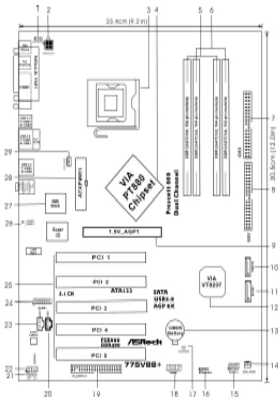
1 PS2_USB_PWR1 Jumper
2 ATX Power Connector (ATX12V1)
3 775-Pin CPU Socket
4 North Bridge Controller
5 2 x 184-pin DDR DIMM Slots (Dual Channel A: DDR1, DDR3; Blue)
6 2 x 184-pin DDR DIMM Slots (Dual Channel B: DDR2, DDR4; Black)
7 Secondary IDE Connector (IDE2, Black)
8 Primary IDE Connector (IDE1, Blue)
9 AGP Slot (1.5V AGP1)
10 Secondary Serial ATA Connector (SATA2)
11 Primary Serial ATA Connector (SATA1)
12 South Bridge Controller
13 CMOS Battery
14 Chasis fan connector (CHA_FAN)
15 System Panel Header (PANEL1)
16 Chasis Speaker Header (SPEAKER 1)
17 Clear CMOS Jumper (CLRCMOS1)
18 USB 2.0 Header (USB67, Blue)
19 Floppy Connector (FLOPPY1)
20 Internal Audio Connector: CD1 (Black)
21 JR1/JL1 Jumper
22 Front Panel Audio Header (AUDIO1)
23 Internal audio connector: AUX1 (White)
24 Game Connector (GAME1)
25 PCI Slots (PCI 1-5)
26 Infrared Module Header (IR1)
27 BIOS chip
28 ATX Power Connector (ATXPWR1)
29 CPU Fan Connector (CPU_FAN1)
ASRock I/O PlusTM
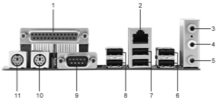
1 Parallel Port
2 RJ-45 Port
3 Line In (Light Blue)
4 Line Out (Lime)
5 Microphone (Pink)
6 USB 2.0 Ports (USB4, USB5)
7 USB 2.0 Ports (USB0, USB1)
8 USB 2.0 Ports (USB2, USB3)
9 Serial Port: COM1
10 PS/2 Keyboard Port (Purple)
11 PS/2 Mouse Port (Green)
1. Introduction
Thank you for purchasing ASRock 775V88/775V88+ motherboard, a reliable motherboard produced under ASRock's consistently stringent quality control. It delivers excellent performance with robust design conforming to ASRock's commitment to quality and endurance.
This Quick Installation Guide contains introduction of the motherboard and step-by-step installation guide. More detailed information of the motherboard can be found in the user manual presented in the Support CD.

Because the motherboard specifications and the BIOS software might be updated, the content of this manual will be subject to change without notice. In case any modifications of this manual occur, the updated version will be available on ASRock website without further notice. You may find the latest memory and CPU support lists on ASRock website as well.
ASRock website http://www.asrock.com
1.1 Package Contents
ASRock 775V88/775V88+ Motherboard
(ATX Form Factor: 12.0-in x 9.2-in, 30.5 cm x 23.4 cm)
ASRock 775V88/775V88+ Quick Installation Guide
ASRock 775V88/775V88+ Support CD
(including LGA 775 CPU Installation Live Demo)
One 80-conductor Ultra ATA 66/100/133 IDE Ribbon Cable
One Ribbon Cable for a 3.5-in Floppy Drive
One Serial ATA (SATA) Cable
One Serial ATA (SATA) HDD Power Cable (Optional)
One ASRock I/O Plus™ Shield
1.2 Specifications
Platform: ATX Form Factor: 12.0-in x 9.2-in, 30.5 cm x 23.4 cm
CPU: 775-Pin Socket
Supports Intel Pentium 4/ Celeron processor (in 775-land
LGA package)
Chipsets: North Bridge:
VIA PT880, FSB @ 800/533 MHz,
with Intel Hyper-Threading Technology ready
(see CAUTION 1)
South Bridge:
VIA VT8237, supports USB 2.0, ATA 133, SATA 1.5Gb/s
Memory: 4 DDR DIMM slots: DDR1, DDR2, DDR3, and DDR4
2 DDR DIMM Slots Support PC3200 (DDR400), Max. 1GB,
4 DDR DIMM Slots Support PC2700 (DDR333) /
PC2100 (DDR266), Max. 3.5GB,
Dual Channel Memory Technology support
(see CAUTION 2)
IDE: IDE1: ATA 133 / Ultra DMA Mode 6
IDE2: ATA 133 / Ultra DMA Mode 6
Support up to 4 IDE devices
Serial ATA: 2 SATA connectors, support up to 1.5Gb/s data transfer rate
Floppy Port: Supports up to 2 floppy disk drives
Audio: 5.1 channels AC'97 Audio
LAN: Speed: 802.3u (10/100 Ethernet), supports Wake-On-LAN
Hardware Monitor: CPU temperature sensing,
Chassis temperature sensing,
CPU overheat shutdown to protect CPU life
(ASRock U-COP)(see CAUTION 3),
CPU fan tachometer,
PCI slots: 5 slots with PCI Specification 2.2
AGP slot: 1 AGP slot, supports 1.5V, 8X/4X AGP card (see CAUTION 4)
USB 2.0: 8 USB 2.0 ports:
include 6 ready-to-use USB 2.0 ports on the rear panel,
plus one on-board header supporting 2 extra USB 2.0 ports
(see CAUTION 5)
ASRock I/O PlusTM: 1 PS/2 mouse port, 1 PS/2 keyboard port,
1 serial port: COM1,
1 parallel port: ECP/EPP support,
6 ready-to-use USB 2.0 ports,
1 RJ 45 port,
Audio Jack: Line In / Line Out / Microphone
BIOS: AMI BIOS,
Supports "Plug and Play",
ACPI 1.1 compliance wake up events,
Supports jumperfree,
SMBIOS 2.3.1 support,
CPU frequency stepless control
(only for advanced users' reference, see CAUTION 6)
OS: Microsoft® Windows® 98SE / ME / 2000 / XP compliant
CAUTION!
- About the setting of "Hyper Threading Technology", please check page 27 in the support CD.
- This motherboard supports Dual Channel Memory Technology. Before you implement Dual Channel Memory Technology, make sure to read the installation guide of memory modules on page 11 for proper installation.
- While CPU overheat is detected, the system will automatically shutdown. Before you resume the system, please check if the CPU fan on the motherboard functions properly and unplug the power cord, then plug it back again. To improve heat dissipation, remember to spray thermal grease between the CPU and the heatsink when you install the PC system.
- Do NOT use a 3.3V AGP card on the AGP slot of this motherboard! It may cause permanent damage!
- Power Management for USB 2.0 works fine under Microsoft® Windows® XP SP1/2000 SP4. It may not work properly under Microsoft® Windows® 98/ ME.
- Although this motherboard offers stepless control, it is not recommended to perform over-clocking. Frequencies other than the recommended CPU bus frequencies may cause the instability of the system or damage the CPU.
2. Installation
775V88/775V88+ is an ATX form factor (12.0-in x 9.2-in, 30.5 cm x 23.4 cm) motherboard. Before you install the motherboard, study the configuration of your chassis to ensure that the motherboard fits into it.
Pre-Installation Precautions
Take note of the following precautions before you install motherboard components or change any motherboard settings.
- Unplug the power cord from the wall socket before touching any component.
- To avoid damaging the motherboard components due to static electricity, NEVER place your motherboard directly on the carpet or the like. Also remember to use a grounded wrist strap or touch a safety grounded object before you handle components.
- Hold components by the edges and do not touch the ICs.
- Whenever you uninstall any component, place it on a grounded anti-static pad or in the bag that comes with the component.

Before you install or remove any component, ensure that the power is switched off or the power cord is detached from the power supply. Failure to do so may cause severe damage to the motherboard, peripherals, and/or components.
2.1 775-LAND CPU Installation
For the installation of Intel 775-LAND CPU, please follow the steps below.
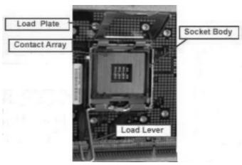
775-Pin Socket Overview

Before you insert the 775-LAND CPU into the socket, please check if the CPU surface is unclean or if there is any bent pin on the socket. Do not force to insert the CPU into the socket if above situation is found. Otherwise, the CPU will be seriously damaged.
Step 1. Open the socket:
Step 1-1. Disengaging the lever by depressing down and out on the hook to clear retention tab.
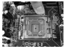
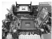
Step 1-2. Rotate the load lever to fully open position at approximately 135 degrees.
Step 1-3. Rotate the load plate to fully open position at approximately 100 degrees.
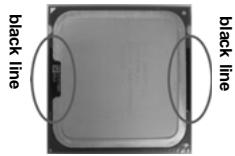
Step 2. Insert the 775-LAND CPU:
Step 2-1. Hold the CPU by the edges where are marked with black lines.
Step 2-2. Orient the CPU with IHS (Integrated Heat Sink) up. Locate Pin1 and the two orientation key notches.
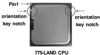
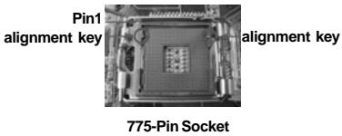

For proper inserting, please ensure to match the two orientation key notches of the CPU with the two alignment keys of the socket.
Step 2-3. Carefully place the CPU into the socket by using a purely vertical motion.
Step 2-4. Verify that the CPU is within the socket and properly mated to the orient keys.
Step 3. Remove PnP Cap (Pick and Place Cap):
Use your left hand index finger and thumb to support the load plate edge, engage PnP cap with right hand thumb and peel the cap from the socket while pressing on center of PnP cap to assist in removal.

It is recommended to use the cap tab to handle and avoid kicking off the PnP cap.
Step 4. Close the socket:
Step 4-1. Rotate the load plate onto the IHS.
Step 4-2. While pressing down lightly on load plate, engage the load lever.
Step 4-3. Secure load lever with load plate tab under retention tab of load lever.
2.2 Installation of CPU Fan and Heatsink
This motherboard is equipped with 775-Pin socket that supports Intel 775-LAND CPU. Please adopt the type of heatsink and cooling fan compliant with Intel 775-LAND CPU to dissipate heat. Before you installed the heatsink, you need to spray thermal interface material between the CPU and the heatsink to improve heat dissipation. Ensure that the CPU and the heatsink are securely fastened and in good contact with each other. Then connect the CPU fan to the CPU_FAN connector (CPU_FAN1, see page 2, No. 29).
For proper installation, please kindly refer to the instruction manuals of your CPU fan and heatsink.
Below is an example to illustrate the installation of the heatsink for 775-LAND CPU.
Step 1. Apply thermal interface material onto center of IHS on the socket surface.
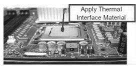
Step 2. Place the heatsink onto the socket. Ensure fan cables are oriented on side closest to the CPU fan connector on the motherboard (CPU_FAN1, see page 2, No. 29).
Step 3. Align fasteners with the motherboard throughholes.
Step 4. Rotate the fastener clockwise, then press down on fastener caps with thumb to install and lock. Repeat with remaining fasteners.
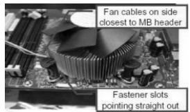

If you press down the fasteners without rotating them clockwise, the heatsink cannot be secured on the motherboard.
Step 5. Connect fan header with the CPU fan connector on the motherboard.
Step 6. Secure excess cable with tie-wrap to ensure cable does not interfere with fan operation or contact other components.
2.3 Installation of Memory Modules (DIMM)
775V88/775V88+ motherboard provides four 184-pin DDR (Double Data Rate) DIMM slots, and supports Dual Channel Memory Technology. For dual channel configuration, you always need to install identical (the same brand, speed, size and chip-type) DDR DIMM pair in the slots of the same color. In other words, you have to install identical DDR DIMM pair in Dual Channel A (DDR1 and DDR3; Blue slots; see p.2 No. 5) or identical DDR DIMM pair in Dual Channel B (DDR2 and DDR4; Black slots; see p.2 No. 6), so that Dual Channel Memory Technology can be activated. This motherboard also allows you to install four DDR DIMMs for dual channel configuration, and please install identical DDR DIMMs in all four slots. You may refer to the Dual Channel Memory Configuration Table below.
Dual Channel Memory Configurations
| DDR1 (Blue Slot) | DDR2 (Black Slot) | DDR3 (Blue Slot) | DDR4 (Black Slot) | |
| (1) | Populated | - | Populated | - |
| (2) | - | Populated | - | Populated |
| (3) | Populated | Populated | Populated | Populated |

- If you want to install two memory modules, for optimal compatibility and reliability, it is recommended to install them in the slots of the same color. In other words, install them either in the set of blue slots (DDR1 and DDR3), or in the set of black slots (DDR2 and DDR4).
- If only one memory module or three memory modules are installed in the DDR DIMM slots on this motherboard, it is unable to activate the Dual Channel Memory Technology.
- If a pair of memory modules is NOT installed in the same Dual Channel, for example, installing a pair of memory modules in DDR1 and DDR2, it is unable to activate the Dual Channel Memory Technology.
Installing a DIMM

Please make sure to disconnect power supply before adding or removing DIMMs or the system components.
STEP1: Unlock a DIMM slot by pressing the retaining clips outward.
STEP2: Align a DIMM on the slot such that the notch on the DIMM matches the break on the slot.
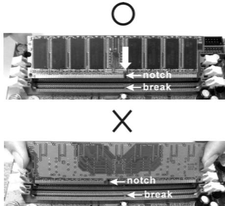

The DIMM only fits in one correct orientation. It will cause permanent damage to the motherboard and the DIMM if you force the DIMM into the slot at incorrect orientation.
STEP 3: Firmly insert the DIMM into the slot until the retaining clips at both ends fully snap back in place and the DIMM is properly seated.
2.4 Expansion Slots (PCI and AGP Slots)
There are 5 PCI slots and 1 AGP slot on 775V88/775V88+ motherboard.
PCI slots: PCI slots are used to install expansion cards that have the 32-bit PCI interface.
AGP slot: The AGP slot is used to install a graphics card. The ASRock AGP slot has a special design of clasp that can securely fasten the inserted graphics card.

Please do NOT use a 3.3V AGP card on the AGP slot of this motherboard! It may cause permanent damage! For the voltage information of your AGP card, please check with the AGP card vendors.
Installing an expansion card
STEP1: Before installing the expansion card, please make sure that the power supply is switched off or the power cord is unplugged. Please read the documentation of the expansion card and make necessary hardware settings for the card before you start the installation.
STEP2: Remove the system unit cover (if your motherboard is already installed in a chassis).
STEP 3: Remove the bracket facing the slot that you intend to use. Keep the screws for later use.
STEP4: Align the card connector with the slot and press firmly until the card is completely seated on the slot.
STEP5: Fasten the card to the chassis with screws.
STEP 6: Replace the system cover.
2.5 Jumpers Setup
The illustration shows how jumpers are setup. When the jumper cap is placed on pins, the jumper is "Short". If no jumper cap is placed on pins, the jumper is "Open". The illustration shows a 3-pin jumper whose pin1 and pin2 are "Short" when jumper cap is placed on these 2 pins.
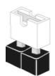
Short

Open

Jumper Setting
PS2_USB_PWR1
(see p.2 No. 1)


+5V

+5VSB
Short pin2, pin3 to enable +5VSB (standby) for PS/2 or USB wake up events.
Note: To select +5VSB, it requires 2 Amp and higher standby current provided by power supply.
JR1(see p.2 No. 21)
JL1(see p.2 No. 21)

JR1 JL1
Note: If the JL1 and JR1 jumpers are short, both the front panel and the rear panel audio connectors can work.
Clear CMOS
(CLRCMOS1, 2-pin jumper)
(see p.2 No.17)

2-pin jumper
Note: CLRCMOS1 allows you to clear the data in CMOS. The data in CMOS includes system setup information such as system password, date, time, and system setup parameters. To clear and reset the system parameters to default setup, please turn off the computer and unplug the power cord, then use a jumper cap to short the pins on CLRCMOS1 for 3 seconds. Please remember to remove the jumper cap after clearing the CMOS. If you need to clear the CMOS when you just finish updating the BIOS, you must boot up the system first, and then shut it down before you do the clear-CMOS action.
2.6 Onboard Headers and Connectors

Onboard headers and connectors are NOT jumpers. Do NOT place jumper caps over these headers and connectors. Placing jumper caps over the headers and connectors will cause permanent damage of the motherboard!
FDD Connector
(33-pin FLOPPY1)
(see p.2 No. 19)
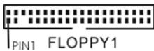
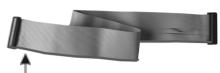
the red-striped side to Pin1
Note: Make sure the red-striped side of the cable is plugged into Pin1 side of the connector.
Primary IDE Connector (Blue)
(39-pin IDE1, see p.2 No. 8)
Secondary IDE Connector (Black)
(39-pin IDE2, see p.2 No. 7)
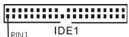
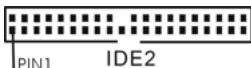
connect the blue end to the motherboard
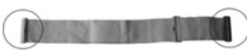
connect the black end to the IDE devices
80-conductor ATA 66/100/133 cable
Note: If you use only one IDE device on this motherboard, please set the IDE device as "Master". Please refer to the instruction of your IDE device vendor for the details. Besides, to optimize compatibility and performance, please connect your hard disk drive to the primary IDE connector (IDE1, blue) and CD-ROM to the secondary IDE connector (IDE2, black).
Serial ATA Connectors
(SATA1: see p.2 No. 11)
(SATA2: see p.2 No. 10)

SATA1
These two Serial ATA (SATA) connectors support SATA data cables for internal storage devices. The current SATA interface allows up to 1.5 Gb/s data transfer rate.
Serial ATA (SATA)
Data Cable
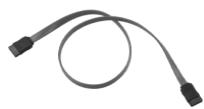
Either end of the SATA data cable can be connected to the SATA hard disk or the SATA connector on the motherboard.
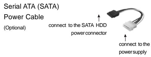
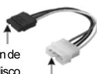
Please connect the black end of SATA power cable to the power connector on the drive. Then connect the white end of SATA power cable to the power connector of the power supply.
USB 2.0 Header (9-pin USB67) (see p.2, No.18)
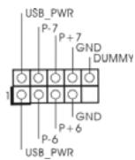
ASRock I/O Plus™ provides you 6 ready-to-use USB 2.0 ports on the rear panel. If the rear USB ports are not sufficient, this USB 2.0 header is available to support 2 extra USB 2.0 ports.
Infrared Module Header (5-pin IR1) (see p.2, No. 26)
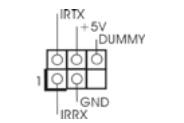
This header supports an optional wireless transmitting and receiving infrared module.
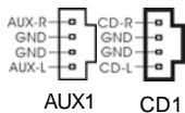
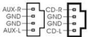
Internal Audio Connectors
(4-pin CD1, 4-pin AUX1)
(CD1: see p.2, No. 20)
(AUX1: see p.2, No. 23)
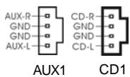
These connectors allow you to receive stereo audio input from sound sources such as a CD-ROM, DVD-ROM, TV tuner card, or MPEG card.
Front Panel Audio Header (9-pin AUDIO1) (see p.2, No. 22)
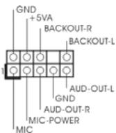
This is an interface for the front panel audio cable that allows convenient connection and control of audio devices.
System Panel Header (9-pin PANEL1) (see p.2, No. 15)
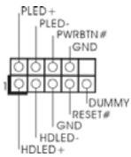
This header accommodates several system front panel functions.
Chassis Speaker Header (4-pin SPEAKER 1) (see p.2, No. 16)
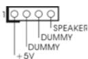
Please connect the chassis speaker to this header.
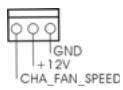
Chassis Fan Connector
(3-pin CHA_FAN1)
(see p.2, No.14)
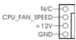
CPU Fan Connector
(4-pinCPU_FAN1)
(see p.2, No.29)
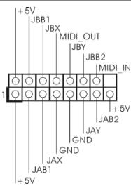
Game Connector
(15-pin GAME1)
(see p.2, No.24)
ATX Power Connector
(20-pinATXPWR1)
(see p.2, No.28)
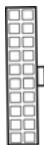
ATX 12V Connector
(4-pin ATX12V1)
(see p.2, No. 2)

Please connect the chassis fan cable to this connector and match the black wire to the ground pin.
You may connect either a 3-pin or a 4-pin CPU fan cable to this connector, then match the black wire to the ground pin.
Connect a Game cable to this connector if the Game port bracket is installed.
Please note that it is necessary to connect a power supply with ATX 12V plug to this connector so that it can provide sufficient power. Failing to do so will cause the failure to power up.
2.7 Serial ATA (SATA) Hard Disks Installation
This motherboard adopts VIA VT8237 southbridge chipset that supports Serial ATA (SATA) hard disks. You may install SATA hard disks on this motherboard for internal storage devices. This section will guide you to install the SATA hard disks.
STEP1: Install the SATA hard disks into the drive bays of your chassis.
STEP2: Connect the SATA power cable to the SATA hard disk.
STEP3: Connect one end of the SATA data cable to the motherboard's SATA connector.
STEP4: Connect the other end of the SATA data cable to the SATA hard disk.
2.8 Hot Plug and Hot Swap Functions for SATA HDDs
775V88/775V88+ motherboard supports Hot Plug and Hot Swap functions for SATA Devices.

NOTE
What is Hot Plug Function?
If the SATA HDDs are NOT set for RAID configuration, it is called "Hot Plug" for the action to insert and remove the SATA HDDs while the system is still power-on and in working condition.
However, please note that it cannot perform Hot Plug if the OS has been installed into the SATA HDD.
What is Hot Swap Function?
If SATA HDDs are built as RAID1 then it is called "Hot Swap" for the action to insert and remove the SATA HDDs while the system is still power-on and in working condition.
2.9 Installing Windows 2000 / Windows XP /
Windows XP 64-bit With RAID Functions
If you want to install Windows 2000 / Windows XP / Windows XP-64bit OS on your system with RAID functions, please refer to the below methods for proper installation according to the different Windows OS versions.
2.9.1 Installing Windows 2000 / Windows XP with RAID Functions
If you want to install Windows 2000 / Windows XP OS on your SATA
HDDs with RAID functions, please follow the below steps.
STEP 1: Make a SATA Driver Diskette.
A. Insert the ASRock Support CD into your optical drive to boot your system.
B. During POST at the beginning of system boot-up, press <F11> key, and then a window for boot devices selection appears. Please select CD-ROM as the boot device.
C. When you see the message on the screen, "Do you want to generate Serial ATA driver diskette [YN]?", press
D. Then you will see these messages, Please insert a diskette into the floppy drive. WARNING! Formatting the floppy diskette will lose ALL data in it! Start to format and copy files [YN]?
Please insert a floppy diskette into the floppy drive, and press
E. The system will start to format the floppy diskette and copy SATA drivers into the floppy diskette.
STEP 2: Use "SATA RAID BIOS" to set RAID configuration.
Before you start to configure the RAID function, you need to check the installation guide in the Support CD for proper configuration. Please refer to the document in the Support CD, "Guide to SATA Hard Disks Installation and RAID Configuration", which is located in the folder at the following path: ..\SATA RAID BIOS
STEP 3: Install Windows 2000 / Windows XP OS on your system.
After making a SATA driver diskette and using "SATA RAID BIOS" to set RAID configuration, you can start to install Windows 2000 / Windows XP on your system.
2.9.2 Installing Windows XP 64-bit With RAID Functions
If you want to install Windows XP 64-bit OS on your SATA HDDs with RAID functions, please follow the below steps.
STEP 1: Make a SATA Driver Diskette.
A. Insert the floppy diskette into your floppy drive.
B. Copy the SATA 64-bit drivers to your floppy diskette.
The SATA 64-bit drivers are located at the following path in the Support CD:
.. 64bit SATA Driver
STEP 2: Install Windows XP 64-bit OS on your system.
After making a SATA driver diskette, you can start to install Windows XP 64-bit on your system.
After the installation of Windows 2000 / Windows XP / Windows XP 64-bit OS, if you want to manage RAID functions, you are allowed to use both "SATA RAID BIOS" and "VIA RAID Tool" for RAID configuration. Please refer to the document in the Support CD, "Guide to SATA Hard Disks Installation and RAID Configuration", which is located in the folder at the following path: ..\SATA RAID BIOS and the document in the support CD, "Guide to VIA RAID Tool", which is located in the folder at the following path: ..\VIA RAID Tool

- Windows 98 / Windows ME does not support RAID functions.
- If you want to use "VIA RAID Tool" in Windows environment, please install SATA drivers from the Support CD again so that "VIA RAID Tool" will be installed to your system as well.
2.10 Installing Windows 98 / ME / 2000 / XP / XP 64-bit Without RAID Functions
If you want to install Windows 98 / ME / 2000 / XP / XP 64-bit on your SATA HDDs without RAID functions or you want to install Windows 98 / ME / 2000 / XP / XP 64-bit on your IDE HDDs instead of SATA HDDs, please refer to the below methods for proper installation according to the different Windows OS versions.
2.10.1 Installing Windows 98 / ME Without RAID Functions
If you want to install Windows 98 / ME on your SATA HDDs without RAID functions or you want to install Windows 98 / ME on your IDE HDDs instead of SATA HDDs, please follow the below steps.
STEP 1: Install Windows 98 / ME OS on your system.
You can start to install Windows 98 / ME on your system directly.
2.10.2 Installing Windows XP / 2000 / XP 64-bit Without RAID Functions
If you want to install Windows XP / 2000 / XP 64-bit on your SATA HDDs without RAID functions or you want to install Windows XP / 2000 / XP 64-bit on your IDE HDDs instead of SATA HDDs, please follow the below steps.
STEP 1: Set Up BIOS.
A. Enter BIOS SETUP UTILITY Advanced screen IDE Configuration.
B. Set the "SATA Operation Mode" option from [RAID] to [non-RAID].
STEP 2: Install Windows 2000 / XP / XP 64-bit OS on your system.
After setting up BIOS, you can start to install Windows 2000 / XP / XP 64-bit on your system.

If you don't want to set up RAID functions, there is no need to make a SATA driver diskette.
3. BIOS Information
The Flash Memory on the motherboard stores BIOS Setup Utility. When you start up the computer, please press
The BIOS Setup program is designed to be user-friendly. It is a menu-driven program, which allows you to scroll through its various sub-menus and to select among the predetermined choices. For the detailed information about BIOS Setup, please refer to the User Manual (PDF file) contained in the Support CD.
4. Software Support CD information
This motherboard supports various Microsoft® Windows® operating systems: 98 SE/ ME / 2000 / XP. The Support CD that came with the motherboard contains necessary drivers and useful utilities that will enhance motherboard features.
To begin using the Support CD, insert the CD into your CD-ROM drive. It will display the Main Menu automatically if "AUTORUN" is enabled in your computer. If the Main Menu does not appear automatically, locate and double-click on the file "ASSETUP.EXE" from the "BIN" folder in the Support CD to display the menus.
1.主板简介
(CLRCMOS1, 2-Pin jumper)
Seriell-ATA-Anschlüsse
(4-Pin CD1, 4-Pin AUX1)
Chipsets: North Bridge:
VIA PT880, FSB @ 800/533 MHz,
supporte la technologie Hyper-Threading
(voir ATTENTION 1)
South Bridge:
VIA VT8237, supporte USB 2.0, ATA 133, SATA 1.5Go/s
Mémoire: 4 slots DIMM DDR: DDR1, DDR2, DDR3, et DDR4
2 emplacements DIMM DDR prenant en charge
PC3200 (DDR400), Maxi. 1 Go,
4 emplacements DIMM DDR prenant en charge
PC2700 (DDR333) / PC2100 (DDR 266), Maxi. 3,5 Go
USB2.0: 8 ports USB2.0:
1 Port parallele: Support ECP/EPP,
BIOS: BIOS AMI, Support du "Plug and Play",
Start to format and copy files [Y/N]?
Piattaforma: ATX Form Factor: 12.0-in x 9.2-in, 30.5 cm x 23.4 cm
Chipset: North Bridge:
VIA PT880, FSB @ 800/533 MHz,
supporta technologia Hyper-Threading
(vedi ATTENZIONE 1)
South Bridge:
VIA VT8237, supporta USB 2.0, ATA 133, SATA 1Gb/s
Memoria: 4 slot DDR DIMM: DDR1, DDR2, DDR3, e DDR4
2 Slot DIMM DDR Slots
Supporto PC3200 (DDR400), Max. 2GB,
4 Slot DIMM DDR Slots Supporto
PC2700 (DDR333) / PC2100 (DDR266), Max. 3.5GB
Supporto Tecnologia Dual Channel Memory
(vedi ATTENZIONE 2)
IDE: IDE1: ATA133 / Ultra DMA Mode 6;
IDE2: ATA133 / Ultra DMA Mode 6;
Supporta AMI legal BIOS, Supporta "Plug and Play",
Compatible con ACPI 1.1 wake up events,
Supporta jumperfree, Supporta SMBIOS 2.3.1
(CLRCMOS1, jumper a 2 pin)
(vedi p.2 Nr.17)

jumper a 2 pin
(4-pin CD1, 4-pin AUX1)
CD1:vedip.2Nr.20)
(AUx1: vedi p.2 Nr. 23)
Chipset: North Bridge:
VIA PT880, FSB @ 800/533/400 MHz,
ACP1.1 compliance wake up events,
Soporta "jumper free setup", Soporta SMBIOS 2.3.1,
Stepless control de Frequencia de CPU
(CLRCMOS1, jumper de 2 pins)
(vep.2,N.17)

jumper de 2 pins
Ambos extremos del cableSEOSEOSEOSEOSEOSEOSEOSEOSEOSEOSEOSEOSEOSEOSEOSEOSEOSEOSEOSEOSEOSEOSEOSEOSEOSEOSEOSEOSEOSEOSEOSEOSEOSEOSEOSEOSEOSEOSEOSEOSEOSEOSEOSEOSEOSEOSEOSEOSEOSEOSEOSEOSEOSEOSEOSEOSEOSEOSEOSEOSEOSEOSEOSEOSEOSEOSEOSEOSEOSEOSEOSEOSEOSEOSEOSEOSEOSEOSEOSEOSEOSEOSEOSEOSEOSEOSEOSEOSEOSEOSEOSEOSEOSEOSEOSEOSEOSEOSEOSEO SEO SEO SEO SEO SEO SEO SEO SEO SEO SEO SEO SEO SEO SEO SEO SEO SEO SEO SEO SEO SEO SEO SEO SEO SEO SEO SEO SEO SEO SEO SEO SEO SEO SEO SEO SEO SEO SEO SEO SEO SEO SEO SEO SEO SEO SEO SEO SEO SEO SEO SEO SEO SEO SEO SEO SEO SEO SEO SEO SEO SEO SEO SEO SEO SEO SEO SEO SEO SEO SEO SEO SEO SEO SEO SEO SEO SEO SEO SEO SEO SEO SEO SEO SEO SEO SEO SEO SEO SEO SEO SEO SEO SEO SEO SEO SEO SEO SEO SEO SEO
Cable de alimentacion de series ATA (SATA)
(Optional)
(4-pin CD1, 4-pin AUX1)
(CD1: ver p.2, N. 20)
(AUX1: ver p.2, N. 23)
AUX1 CD1