775I65G - Motherboard ASROCK - Free user manual and instructions
Find the device manual for free 775I65G ASROCK in PDF.
| Product Type | Micro ATX Motherboard |
| Brand | ASRock |
| Model | 775i65G |
| Dimensions | 24.4 cm x 20.3 cm (9.6 x 8.0 inches) |
| Form Factor | Micro ATX |
| CPU Socket | LGA 775 |
| Chipset | Intel 865G (Northbridge) / ICH5 (Southbridge) |
| Supported Memory | DDR400/333/266, up to 2 GB, 2 DIMM slots |
| Expansion Slots | 3 PCI, 1 AGP 8X/4X (1.5V), 1 AMR |
| Integrated Graphics | Intel Extreme Graphics 2, shared memory up to 96 MB |
| Audio | Cmedia 9761A, 5.1 channel |
| Network | Realtek 8101L, 10/100 Ethernet, Wake-On-LAN |
| Rear Ports | 1 PS/2 mouse, 1 PS/2 keyboard, 1 VGA, 1 parallel, 6 USB 2.0, 1 RJ-45, 3 audio jacks |
| Internal Connectors | 2 SATA, 2 ATA100 IDE, 1 FDD, 1 IR, 1 COM, 1 USB 2.0 header, 1 shared USB, front audio, CPU/chassis fan, ATX 20-pin + 12V 4-pin |
| BIOS | AMI 4 MB, Plug & Play, ACPI 1.1, SMBIOS 2.3.1 |
| Supported Operating Systems | Windows 98SE/ME/2000/XP |
| Required Power Supply | ATX 20-pin connector + 12V 4-pin connector |
| Approximate Weight | 0.5 kg |
| Maintenance and Cleaning | Disconnect power before handling. Use an antistatic wrist strap. Clean with a dry, lint-free cloth. Do not use liquid solvents. |
| Safety | Overclocking risks: may damage the system. Do not use 3.3V AGP card. Protected against overheating (U-COP). |
| Spare Parts and Repairability | CPU, RAM, graphics card and other replaceable components. Included cables: IDE, FDD, SATA (optional). Parts available online. |
| General Information | Reliable and high-performance motherboard for desktop PCs. User manual available on the included CD and online. |
Frequently Asked Questions - 775I65G ASROCK
User questions about 775I65G ASROCK
0 question about this device. Answer the ones you know or ask your own.
Ask a new question about this device
Download the instructions for your Motherboard in PDF format for free! Find your manual 775I65G - ASROCK and take your electronic device back in hand. On this page are published all the documents necessary for the use of your device. 775I65G by ASROCK.
USER MANUAL 775I65G ASROCK
No part of this installation guide may be reproduced, transcribed, transmitted, or translated in any language, in any form or by any means, except duplication of documentation by the purchaser for backup purpose, without written consent of ASRock Inc.
Products and corporate names appearing in this guide may or may not be registered trademarks or copyrights of their respective companies, and are used only for identification or explanation and to the owners' benefit, without intent to infringe.
Disclaimer:
Specifications and information contained in this guide are furnished for informational use only and subject to change without notice, and should not be constructed as a commitment by ASRock. ASRock assumes no responsibility for any errors or omissions that may appear in this guide.
With respect to the contents of this guide, ASRock does not provide warranty of any kind, either expressed or implied, including but not limited to the implied warranties or conditions of merchantability or fitness for a particular purpose. In no event shall ASRock, its directors, officers, employees, or agents be liable for any indirect, special, incidental, or consequential damages (including damages for loss of profits, loss of business, loss of data, interruption of business and the like), even if ASRock has been advised of the possibility of such damages arising from any defect or error in the guide or product.

This device complies with Part 15 of the FCC Rules. Operation is subject to the following two conditions:
(1) this device may not cause harmful interference, and
(2) this device must accept any interference received, including interference that may cause undesired operation.
CALIFORNIA, USA ONLY
The Lithium battery adopted on this motherboard contains Perchlorate, a toxic substance controlled in Perchlorate Best Management Practices (BMP) regulations passed by the California Legislature. When you discard the Lithium battery in California, USA, please follow the related regulations in advance.
"Perchlorate Material-special handling may apply, see www.dtsc.ca.gov/hazardouswaste/perchlorate"
ASRock Website: http://www.asrock.com
Published February 2007
Copyright©2007 ASRock INC. All rights reserved.
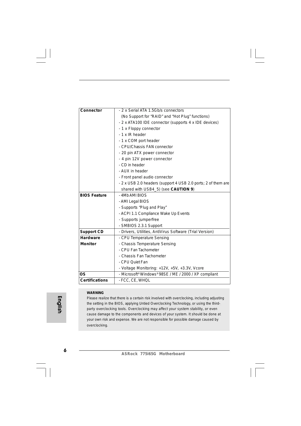
Motherboard Layout
text_image
20.3cm (8.0 in) 29 24.4cm (9.6 in) 1 2 3 4 5 6 7 ATX12V1 PP2 USB, PORT PS2 Mouse PS2 Keyboard VGA1 PARALLEL PORT USB 2.0 T: USB2 B: USB3 USB 2.0 T: USB2 B: USB3 USB 2.0 T: USB4 B: USB5 USB 2.0 T: USB6 USB 2.0 T: USB7 USB 2.0 T: USB8 USB 2.0 T: USB9 USB 2.0 T: USB10 USB 2.0 T: USB11 USB 2.0 T: USB12 USB 2.0 T: USB13 USB 2.0 T: USB14 USB 2.0 T: USB15 USB 2.0 T: USB16 USB 2.0 T: USB17 USB 2.0 T: USB18 USB 2.0 T: USB19 USB 2.0 T: USB20 USB 2.0 T: USB21 USB 2.0 T: USB22 USB 2.0 T: USB23 USB 2.0 T: USB24 USB 2.0 T: USB25 USB 2.0 T: USB26 USB 2.0 T: USB27 USB 2.0 T: USB28 USB 2.0 T: USB29 USB 2.0 T: USB30 USB 2.0 T: USB31 USB 2.0 T: USB32 USB 2.0 T: USB33 USB 2.0 T: USB34 USB 2.0 T: USB35 USB 2.0 T: USB36 USB 2.0 T: USB37 USB 2.0 T: USB38 USB 2.0 T: USB39 USB 2.0 T: USB40 USB 2.0 T: USB41 USB 2.0 T: USB42 USB 2.0 T: USB43 USB 2.0 T: USB44 USB 2.0 T: USB45 USB 2.0 T: USB46 USB 2.0 T: USB47 USB 2.0 T: USB48 USB 2.0 T: USB49 USB 2.0 T: USB50 USB 2.0 T: USB51 USB 2.0 T: USB52 USB 2.0 T: USB53 USB 2.0 T: USB54 USB 2.0 T: USB55 USB 2.0 T: USB56 USB 2.0 T: USB57 USB 2.0 T: USB58 USB 2.0 T: USB59 USB 2.0 T: USB60 USB 2.0 T: USB61 USB 2.0 T: USB62 USB 2.0 T: USB63 USB 2.0 T: USB64 USB 2.0 T: USB65 USB 2.0 T: USB66 USB 2.0 T: USB67 USB 2.0 T: USB68 USB 2.0 T: USB69 USB 2.0 T: USB70 USB 2.0 T: USB71 USB 2.0 T: USB72 USB 2.0 T: USB73 USB 2.0 T: USB74 USB 2.0 T: USB75 USB 2.0 T: USB76 USB 2.0 T: USB77 USB 2.0 T: USB78 USB 2.0 T: USB79 USB 2.0 T: USB80 USB 2.0 T: USB81 USB 2.0 T: USB82 USB 2.0 T: USB83 INTL G65G Chipset ATXPWR1 AGP8X 1.5V_AGP1 PCI LAN PCI LAN PCI 1/ASRock PCI 1/ASRock PCI 1/ASRock PCI 1/ASRock PCI 1/ASRock PCI 1/ASRock PCI 1/ASRock PCI 1/ASRock PCI 1/ASRock PCI 1/ASRock PCI 1/ASRock PCI 1/ASRock PCI 1/ASRock PCI 1/ASRock PCI 1/ASRock CPU ICH5 CPU ICH5 CPU ICH5 CPU ICH5 CPU ICH5 CPU ICH5 CPU ICH5 CPU ICH5 CPU ICH5 CPU ICH5 CPU ICH5 CPU ICH5 CPU ICH5 CPU ICH5 CPU ICH5 CPU ICH5 CPU ICH5 CPU ICH51 PS2_USB_PWR1 Jumper
2 ATX 12V Connector (ATX12V1)
3 ATX Power Connector (ATXPWR1)
4 775-Pin CPU Socket
5 North Bridge Controller
6 CPU Fan Connector (CPU_FAN1)
7 184-pin DDR DIMM Slots (DDR1-2)
8 Secondary IDE Connector (IDE2, Black)
9 Primary IDE Connector (IDE1, Blue)
10 South Bridge Controller
11 Secondary Serial ATA Connector (SATA2)
12 Primary Serial ATA Connector (SATA1)
13 Chassis Fan Connector (CHA_FAN1)
14 System Panel Header (PANEL1)
15 Chassis Speaker Header (SPEAKER 1)
16 Infrared Module Header (IR1)
17 Clear CMOS Jumper (CLRCMOS0)
18 USB 2.0 Header (USB67, Blue)
19 Floppy Connector (FLOPPY1)
20 Serial Port Connector (COM1)
21 AMR Slot (AMR1)
22 Front Panel Audio Header (AUDIO1)
23 JR1/JL1 Jumpers
24 Internal Audio Connector: CD1 (Black)
25 Internal Audio Connector: AUX1 (White)
26 PCI Slots (PCI1-3)
27 AGP Slot (1.5V_AGP1)
28 BIOS FWH Chip
29 Shared USB 2.0 Header (USB4_5, Blue)
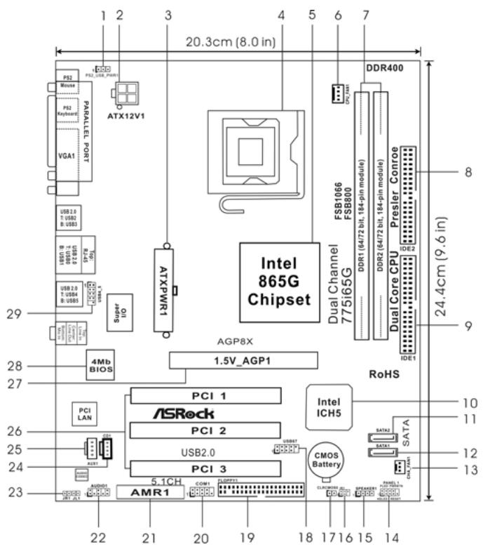
ASRock I/O Plus™
text_image
1 2 3 4 5 6 7 8 9 10 111 Parallel Port
2 RJ-45 Port
3 Line In (Light Blue)
4 Line Out (Lime)
5 Microphone (Pink)
6 Shared USB 2.0 Ports (USB45)
7 USB 2.0 Ports (USB01)
8 USB 2.0 Ports (USB23)
9 VGA Port
10 PS/2 Keyboard Port (Purple)
11 PS/2 Mouse Port (Green)
1. Introduction
Thank you for purchasing ASRock 775i65G motherboard, a reliable motherboard produced under ASRock's consistently stringent quality control. It delivers excellent performance with robust design conforming to ASRock's commitment to quality and endurance.
This Quick Installation Guide contains introduction of the motherboard and step-by-step installation guide. More detailed information of the motherboard can be found in the user manual presented in the Support CD.

Because the motherboard specifications and the BIOS software might be updated, the content of this manual will be subject to change without notice. In case any modifications of this manual occur, the updated version will be available on ASRock website without further notice. You may find the latest VGA cards and CPU support lists on ASRock website as well.
ASRock website http://www.asrock.com
1.1 Package Contents
ASRock 775i65G Motherboard
(Micro ATX Form Factor: 9.6-in x 8.0-in, 24.4 cm x 20.3 cm)
ASRock 775i65G Quick Installation Guide
ASRock 775i65G Support CD
One 80-conductor Ultra ATA 66/100 IDE Ribbon Cable
One Ribbon Cable for a 3.5-in Floppy Drive
One Serial ATA (SATA) Data Cable (Optional)
One Serial ATA (SATA) HDD Power Cable (Optional)
One ASRock I/O Plus™ Shield
One COM Port Bracket
One ASRock MR Card (Optional)
1.2 Specifications
| Platform | - Micro ATX Form Factor: 9.6-in x 8.0-in, 24.4 cm x 20.3 cm |
| CPU | - LGA 775 for Intel® CoreTM 2 Extreme / CoreTM 2 Duo / Pentium® XE / Pentium® D / Pentium® 4 / Celeron® D, supporting Quad Core Kentsfield processors- FSB 1066 MHz for external graphics (seeCAUTION 1)- FSB 800/533 MHz for internal graphics- Supports Hyper-Threading Technology (seeCAUTION 2)- Supports Untied Overclocking Technology (seeCAUTION 3)- Supports EM64T CPU |
| Chipset | - Northbridge: Intel® 865G- Southbridge: Intel® ICH5 |
| Memory | - Dual Channel DDR Memory Technology (seeCAUTION 4)- 2 x DDR DIMM slots- Support DDR400/333/266 (seeCAUTION 5)- Max. capacity: 2GB |
| Hybrid Booster | - CPU Frequency Stepless Control (seeCAUTION 6)- ASRock U-COP (seeCAUTION 7)- Boot Failure Guard (B.F.G.) |
| Expansion Slot | - 3 x PCI slots- 1 x AGP slot for 1.5V 8X/4X AGP card (seeCAUTION 8)- 1 x AMR slot |
| Graphics | - Integrated Intel® Extreme Graphics 2- DirectX 8.0 VGA- Max. shared memory 96MB |
| Audio | - Cmedia 9761A 5.1 channel audio CODEC |
| LAN | - Realtek PCI LAN 8101L- Speed: 10/100 Ethernet- Supports Wake-On-LAN |
| Rear Panel I/O | ASRock I/O PlusTM- 1 x PS/2 Mouse Port- 1 x PS/2 Keyboard Port- 1 x VGA Port- 1 x Parallel Port (ECP/EPP Support)- 6 x Ready-to-Use USB 2.0 Ports- 1 x RJ-45 Port- Audio Jack: Line In / Line Out / Microphone |
English
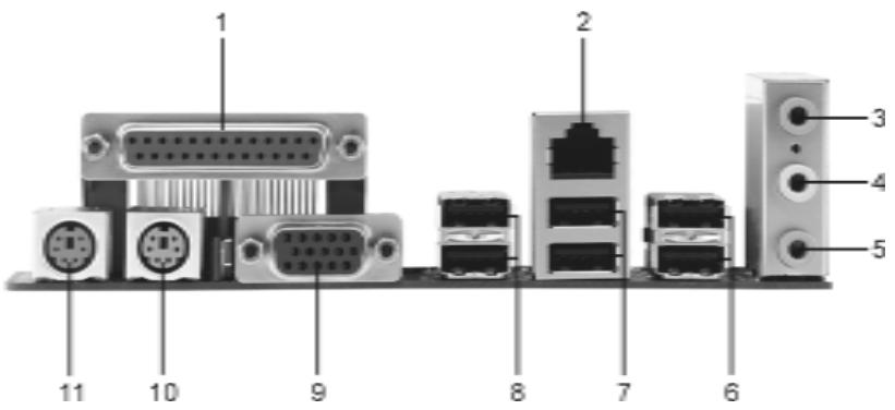
| Connector | - 2 x Serial ATA 1.5Gb/s connectors(No Support for “RAID” and “Hot Plug” functions)- 2 x ATA100 IDE connector (supports 4 x IDE devices)- 1 x Floppy connector- 1 x IR header- 1 x COM port header- CPU/Chassis FAN connector- 20 pin ATX power connector- 4 pin 12V power connector- CD in header- AUX in header- Front panel audio connector- 2 x USB 2.0 headers (support 4 USB 2.0 ports; 2 of them are shared with USB4_5) (seeCAUTION 9) |
| BIOS Feature | - 4Mb AMI BIOS- AMI Legal BIOS- Supports “Plug and Play”- ACPI 1.1 Compliance Wake Up Events- Supports jumperfree- SMBIOS 2.3.1 Support |
| Support CD | - Drivers, Utilities, AntiVirus Software (Trial Version) |
| Hardware Monitor | - CPU Temperature Sensing- Chassis Temperature Sensing- CPU Fan Tachometer- Chassis Fan Tachometer- CPU Quiet Fan- Voltage Monitoring: +12V, +5V, +3.3V, Vcore |
| OS | - Microsoft® Windows® 98SE / ME / 2000 / XP compliant |
| Certifications | - FCC, CE, WHQL |
WARNING
Please realize that there is a certain risk involved with overclocking, including adjusting the setting in the BIOS, applying Untied Overclocking Technology, or using the third-party overclocking tools. Overclocking may affect your system stability, or even cause damage to the components and devices of your system. It should be done at your own risk and expense. We are not responsible for possible damage caused by overclocking.
CAUTION!
- FSB1066-CPU is supported only when you install AGP VGA card into AGP slot. Besides, if you use a FSB1066-CPU on this motherboard, please adopt a DDR400 CL2.5 memory module.
- About the setting of "Hyper Threading Technology", please check page 25 of "User Manual" in the support CD.
- This motherboard supports Untied Overclocking Technology. Please read "Untied Overclocking Technology" on page 18 for details.
- This motherboard supports Dual Channel Memory Technology. Before you implement Dual Channel Memory Technology, make sure to read the installation guide of memory modules on page 11 for proper installation.
- Please check the table below for the memory support frequency and its corresponding CPU FSB frequency.
| CPU FSB Frequency | Memory Support Frequency |
| 800 | DDR266, DDR320*, DDR400 |
| 533 | DDR266, DDR333 |
* When you use an FSB800-CPU on this motherboard, it will run at DDR320 if you adopt a DDR333 memory module.
- Although this motherboard offers stepless control, it is not recommended to perform over-clocking. Frequencies other than the recommended CPU bus frequencies may cause the instability of the system or damage the CPU.
- While CPU overheat is detected, the system will automatically shutdown. Before you resume the system, please check if the CPU fan on the motherboard functions properly and unplug the power cord, then plug it back again. To improve heat dissipation, remember to spray thermal grease between the CPU and the heatsink when you install the PC system.
- Do NOT use a 3.3V AGP card on the AGP slot of this motherboard! It may cause permanent damage!
- Power Management for USB 2.0 works fine under Microsoft® Windows® XP SP1 or SP2 / 2000 SP4. It may not work properly under Microsoft® Windows® 98/ ME.
2. Installation
Pre-installation Precautions
Take note of the following precautions before you install motherboard components or change any motherboard settings.
- Unplug the power cord from the wall socket before touching any component. Failure to do so may cause severe damage to the motherboard, peripherals, and/or components.
- To avoid damaging the motherboard components due to static electricity, NEVER place your motherboard directly on the carpet or the like. Also remember to use a grounded wrist strap or touch a safety grounded object before you handle components.
- Hold components by the edges and do not touch the ICs.
- Whenever you uninstall any component, place it on a grounded antstatic pad or in the bag that comes with the component.
- When placing screws into the screw holes to secure the motherboard to the chassis, please do not over-tighten the screws! Doing so may damage the motherboard.
2.1 CPU Installation
For the installation of Intel 775-LAND CPU, please follow the steps below.
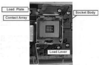
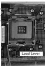
text_image
Load Plate Contact Array Socket Body Load Lever775-Pin Socket Overview

Before you insert the 775-LAND CPU into the socket, please check if the CPU surface is unclean or if there is any bent pin on the socket. Do not force to insert the CPU into the socket if above situation is found. Otherwise, the CPU will be seriously damaged.
Step 1. Open the socket:
Step 1-1. Disengaging the lever by depressing down and out on the hook to clear retention tab.
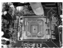
Step 1-2. Rotate the load lever to fully open position at approximately 135 degrees.
Step 1-3. Rotate the load plate to fully open position at approximately 100 degrees.
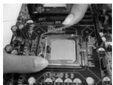
Step 2. Insert the 775-LAND CPU:
Step 2-1. Hold the CPU by the edges where are marked with black lines.
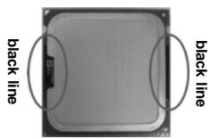
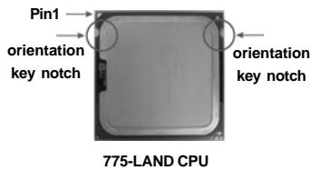
Step 2-2. Orient the CPU with IHS (Integrated Heat Sink) up. Locate Pin1 and the two orientation key notches.
text_image
Pin1 orientation key notch orientation key notch 775-LAND CPU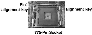
text_image
Pin1 alignment key alignment key 775-Pin Socket
For proper inserting, please ensure to match the two orientation key notches of the CPU with the two alignment keys of the socket.
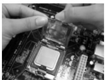
Step 2-3. Carefully place the CPU into the socket by using a purely vertical motion.
Step 2-4. Verify that the CPU is within the socket and properly mated to the orient keys.
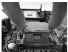
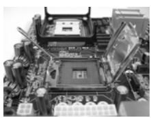
Step 3. Remove PnP Cap (Pick and Place Cap):
Use your left hand index finger and thumb to support the load plate edge, engage PnP cap with right hand thumb and peel the cap from the socket while pressing on center of PnP cap to assist in removal.

- It is recommended to use the cap tab to handle and avoid kicking off the PnP cap.
- This cap must be placed if returning the motherboard for after service.
Step 4. Close the socket:
Step 4-1. Rotate the load plate onto the IHS.
Step 4-2. While pressing down lightly on load plate, engage the load lever.
Step 4-3. Secure load lever with load plate tab under retention tab of load lever.
2.2 Installation of CPU Fan and Heatsink
For proper installation, please kindly refer to the instruction manuals of your CPU fan and heatsink.
Below is an example to illustrate the installation of the heatsink for 775-LAND CPU.
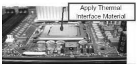
Step 1. Apply thermal interface material onto center of IHS on the socket surface.
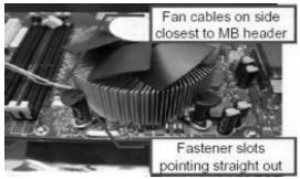
Step 2. Place the heatsink onto the socket. Ensure fan cables are oriented on side closest to the CPU fan connector on the motherboard (CPU_FAN1, see page 2, No. 6).
Step 3. Align fasteners with the motherboard throughholes.
Step 4. Rotate the fastener clockwise, then press down on fastener caps with thumb to install and lock. Repeat with remaining fasteners.
text_image
Fan cables on side closest to MB header Fastener slots pointing straight out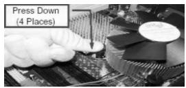

If you press down the fasteners without rotating them clockwise, the heatsink cannot be secured on the motherboard.
Step 5. Connect fan header with the CPU fan connector on the motherboard.
Step 6. Secure excess cable with tie-wrap to ensure cable does not interfere with fan operation or contact other components.
2.3 Installation of Memory Modules (DIMM)
This motherboard provides two 184-pin DDR (Double Data Rate) DIMM slots, and supports Dual Channel Memory Technology. For dual channel configuration, you always need to install two identical (the same brand, speed, size and chip-type) memory modules in the DDR DIMM slots to activate Dual Channel Memory Technology. Otherwise, it will operate at single channel mode.

If you install only one memory module or two non-identical memory modules, it is unable to activate the Dual Channel Memory Technology.
Installing a DIMM

Please make sure to disconnect power supply before adding or removing DIMMs or the system components.
Step 1. Unlock a DIMM slot by pressing the retaining clips outward.
Step 2. Align a DIMM on the slot such that the notch on the DIMM matches the break on the slot.
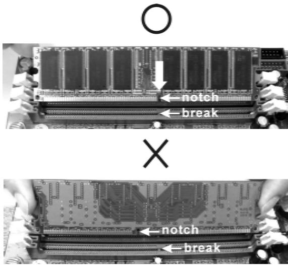
text_image
O ← notch ← break X ← notch ← break
The DIMM only fits in one correct orientation. It will cause permanent damage to the motherboard and the DIMM if you force the DIMM into the slot at incorrect orientation.
Step 3. Firmly insert the DIMM into the slot until the retaining clips at both ends fully snap back in place and the DIMM is properly seated.
2.4 Expansion Slots (PCI, AGP and AMR Slots)
There are 3 PCI slots, 1 AGP slot, and 1 AMR slot on this motherboard.
PCI slots: The PCI slots are used to install expansion cards that have the 32-bit PCI interface.
AGP slot: The AGP slot is used to install a graphics card. The ASRock AGP slot has a special design of clasp that can securely fasten the inserted graphics card.

Do NOT use a 3.3V AGP card on the AGP slot of this motherboard! It may cause permanent damage!
AMR slot: AMR slot is used to insert an ASRock MR card (optional) with v.92 Modem functionality.
Installing an expansion card
Step 1. Before installing the expansion card, please make sure that the power supply is switched off or the power cord is unplugged. Please read the documentation of the expansion card and make necessary hardware settings for the card before you start the installation.
Step 2. Remove the system unit cover (if your motherboard is already installed in a chassis).
Step 3. Remove the bracket facing the slot that you intend to use. Keep the screws for later use.
Step 4. Align the card connector with the slot and press firmly until the card is completely seated on the slot.
Step 5. Fasten the card to the chassis with screws.
Step 6. Replace the system cover.
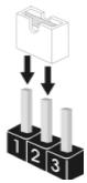
2.5 Jumpers Setup
The illustration shows how jumpers are setup. When the jumper cap is placed on pins, the jumper is "Short". If no jumper cap is placed on pins, the jumper is "Open". The illustration shows a 3-pin jumper whose pin1 and pin2 are "Short" when jumper cap is placed on these 2 pins.
Short

Open
Jumper
Setting
PS2_USB_PWR1
(see p.2 No. 1)

+5V

+5VSB
Short pin2, pin3 to enable +5VSB (standby) for PS/2 or USB wake up events.
Note: To select +5VSB, it requires 2 Amp and higher standby current provided by power supply.
JR1(see p.2 No. 23)
JL1(see p.2 No. 23)

JR1 JL1
Note: If the JL1 and JR1 jumpers are short, both the front panel and the rear panel audio connectors can work.
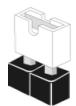
Clear CMOS
(CLRCMOS0, 2-pin jumper)
(see p.2 No. 17)

2-pin jumper
Note: CLRCMOS0 allows you to clear the data in CMOS. The data in CMOS includes system setup information such as system password, date, time, and system setup parameters. To clear and reset the system parameters to default setup, please turn off the computer and unplug the power cord from the power supply. After waiting for 15 seconds, use a jumper cap to short 2 pins on CLRCMOS0 for 5 seconds.
2.6 Onboard Headers and Connectors

Onboard headers and connectors are NOT jumpers. Do NOT place jumper caps over these headers and connectors. Placing jumper caps over the headers and connectors will cause permanent damage of the motherboard!
FDD Connector
(33-pin FLOPPY1)
(see p.2 No. 19)
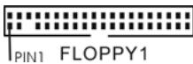
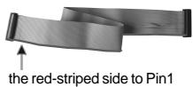
Note: Make sure the red-striped side of the cable is plugged into Pin1 side of the connector.
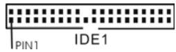
Primary IDE Connector (Blue)
(39-pin IDE1, see p.2 No. 9)
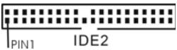
Secondary IDE Connector (Black)
(39-pin IDE2, see p.2 No. 8)
connect the blue end to the motherboard
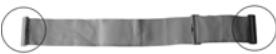
connect the black end to the IDE devices
80-conductor ATA 66/100 cable
Note: If you use only one IDE device on this motherboard, please set the IDE device as "Master". Please refer to the instruction of your IDE device vendor for the details. Besides, to optimize compatibility and performance, please connect your hard disk drive to the primary IDE connector (IDE1, blue) and CD-ROM to the secondary IDE connector (IDE2, black).
Serial ATA Connectors
(SATA1: see p.2 No. 12)
(SATA2: see p.2 No. 11)

SATA2

SATA1
These two Serial ATA (SATA) connectors support SATA data cables for internal storage devices. The current SATA interface allows up to 1.5 Gb/s data transfer rate.
Serial ATA (SATA)
Data Cable
(Optional)
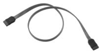
Either end of the SATA data cable can be connected to the SATA hard disk or the SATA connector on the motherboard.
Serial ATA (SATA)
Power Cable
(Optional)
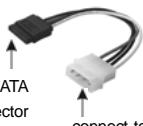
connect to the SATA
HDD power connector
connect to the
powersupply
Please connect the black end of SATA power cable to the power connector on the drive. Then connect the white end of SATA power cable to the power connector of the power supply.
USB 2.0 Header
(9-pin USB67)
(see p.2 No. 18)
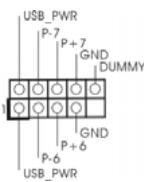
ASRock I/O Plus™ provides you 6 ready-to-use USB 2.0 ports on the rear panel. If the rear USB ports are not sufficient, this USB 2.0 header is available to support 2 extra USB 2.0 ports.
Shared USB 2.0 Header
(9-pin USB4_5)
(see p.2 No. 29)
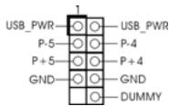
This USB4_5 connector is shared with the USB 2.0 ports 4,5 on ASRock I/O Plus™. When using the front panel USB ports by attaching the front panel USB cable to this connector (USB4_5), the USB ports 4,5 on ASRock I/O Plus™ will not be able to function.
Infrared Module Header
(5-pin IR1)
(see p.2 No. 16)
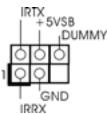
This header supports an optional wireless transmitting and receiving infrared module.
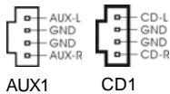
Internal Audio Connectors
(4-pin CD1, 4-pin AUX1)
(CD1: see p.2 No. 24)
(AUX1: see p.2 No. 25)

AUX1

CD1
These connectors allow you to receive stereo audio input from sound sources such as a CD-ROM, DVD-ROM, TV tuner card, or MPEG card.
Front Panel AC'97 Audio Header
(8-pin AUDIO1)
(see p.2 No. 22)
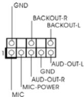
This is an interface for the front panel audio cable that allows convenient connection and control of audio devices.

- +5VA is used for audio power only, please don't connect it to any other power, such as USB.
- HD (Azalia) audio front panel and AC'97 audio front panel have different pin-definition. Incorrect connection of the audio front panel and the front panel audio header may cause permanent damage to this motherboard.
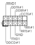
System Panel Header
(9-pin PANEL1)
(see p.2 No. 14)
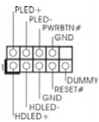
This header accommodates several system front panel functions.
Chassis Speaker Header
(4-pin SPEAKER 1)
(see p.2 No. 15)
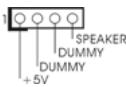
Please connect the chassis speaker to this header.
Chassis Fan Connector
(3-pin CHA_FAN1)
(see p.2 No. 13)
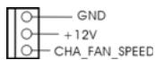
Please connect the chassis fan cable to this connector and match the black wire to the ground pin.
CPU Fan Connector
(4-pin CPU_FAN1)
(see p.2 No. 6)
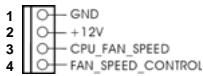
Please connect the CPU fan cable to this connector and match the black wire to the ground pin.

Though this motherboard provides 4-Pin CPU fan (Quiet Fan) support, the 3-Pin CPU fan still can work successfully even without the fan speed control function. If you plan to connect the 3-Pin CPU fan to the CPU fan connector on this motherboard, please connect it to Pin 1-3.
Pin 1-3 Connected
3-Pin Fan Installation
ATX Power Connector
(20-pin ATXPWR1)
(see p.2 No. 3)
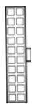
Please connect an ATX power supply to this connector.
ATX 12V Connector
(4-pin ATX12V1)
(see p.2 No. 2)

Please note that it is necessary to connect a power supply with ATX 12V plug to this connector so that it can provides sufficient power. Failing to do so will cause the failure to power up.
Serial port connector
(9-pin COM1)
(see p.2 No. 20)
This COM1 connector
supports a serial port module.
2.7 Serial ATA (SATA) Hard Disks Installation
This motherboard adopts Intel ^® ICH5 south bridge chipset that supports Serial ATA (SATA) hard disks. You may install SATA hard disks on this motherboard for internal storage devices. This section will guide you to install the SATA hard disks.
STEP 1: Install the SATA hard disks into the drive bays of your chassis.
STEP2: Connect the SATA power cable to the SATA hard disk.
STEP 3: Connect one end of the SATA data cable to the motherboard's primary SATA connector (SATA1).
STEP 4: Connect the other end of the SATA data cable to the primary SATA hard disk. If you just want to install only one SATA HDD, the installation process is complete at this step. If you want to install two SATA HDDs, please continue to do the following steps.
STEP5: Connect the SATA power cable to the SATA hard disk.
STEP 6: Connect one end of the second SATA data cable to the motherboard's secondary SATA connector (SATA2).
STEP 7: Connect the other end of the SATA data cable to the secondary SATA hard disk.

Before you install OS into the SATA hard disk, you need to check and ensure the configuration of the OnBoard IDE Operate Mode option in BIOS setup is correct according to the condition of your system. For the configuration details, please refer to the instruction on page 29 of "User Manual" in the support CD.
2.8 Driver Installation Guide
To install the drivers to your system, please insert the support CD to your optical drive first. Then, the drivers compatible to your system can be auto-detected and listed on the support CD driver page. Please follow the order from up to bottom side to install those required drivers. Therefore, the drivers you install can work properly.
2.9 Untied Overclocking Technology
This motherboard supports Untied Overclocking Technology, which means during overclocking, FSB enjoys better margin due to fixed AGP / PCI bus. You may set “CPU Host Frequency” option of BIOS setup to [Auto], which will show you the actual CPU host frequency in the following item. Therefore, CPU FSB is untied during overclocking, but AGP / PCI bus is in the fixed mode so that FSB can operate under a more stable overclocking environment.

Please refer to the warning on page 6 for the possible overclocking risk before you apply Untied Overclocking Technology.
3. BIOS Information
The Flash Memory on the motherboard stores BIOS Setup Utility. When you start up the computer, please press
The BIOS Setup program is designed to be user-friendly. It is a menu-driven program, which allows you to scroll through its various sub-menus and to select among the predetermined choices. For the detailed information about BIOS Setup, please refer to the User Manual (PDF file) contained in the Support CD.
4. Software Support CD information
This motherboard supports various Microsoft® Windows® operating systems: 98 SE / ME / 2000 / XP. The Support CD that came with the motherboard contains necessary drivers and useful utilities that will enhance motherboard features.
To begin using the Support CD, insert the CD into your CD-ROM drive. It will display the Main Menu automatically if “AUTORUN” is enabled in your computer. If the Main Menu does not appear automatically, locate and double-click on the file
"ASSETUP.EXE" from the BIN folder in the Support CD to display the menus.
1. Einführung
ASRock 775i65G Support-CD
2.1 CPU Installation
text_image
Fan cables on side closest to MB header Fastener slots pointing straight outtext_image
○ ← notch ← break × ← notch ← break
(CLRCMOS0, 2-Pin jumper)
Seriell-ATA-Anschlüsse
(4-Pin CD1, 4-Pin AUX1)
The Ground Truth image displays a single, solid horizontal line. According to Rule 2 (UNDERSCORE & LINE RULES), this is a stylistic or background line, not a placeholder underscore. Therefore, the OCR result must ignore it and output nothing or only meaningful text. The provided OCR content is "____", which consists of four underscores. This is an incorrect interpretation of the line as a placeholder, violating the rule that stylistic lines must be ignored. The OCR has hallucinated underscores where none should exist based on the GT's visual context. Hence, the OCR result is inconsistent with the Ground Truth.
Contact Array
(Barrette de contact)
(Corps du
socket)
Socket Body
text_image
Fan cables on side closest to MB header Fastener slots pointing straight out(Orifices des attaches ressortant)
(CD1 br. 4, AUX1 br. 4)
(Micro ATX Form Factor: 9.6-in x 8.0-in, 24.4 cm x 20.3 cm)
text_image
Fan cables on side closest to MB header Fastener slots pointing straight outtext_image
○ ← notch ← break × ← notch ← break
(4-pin CD1, 4-pin AUX1)
(CD1: vedi p.2 Nr. 24)
(AUx1: vedi p.2 Nr. 25)

AUX1

CD1
text_image
Fan cables on side closest to MB header Fastener slots pointing straight outtext_image
O ← notch ← break X ← notch ← break
(4-pin CD1, 4-pin AUX1)
(CD1: ver p.2, N. 24)
(AUX1: ver p.2, N. 25)