Pitstop Smart 11 Kw - Washing machine CECOTEC - Free user manual and instructions
Find the device manual for free Pitstop Smart 11 Kw CECOTEC in PDF.


| Product Type | Electric vehicle charging station |
| Brand | Cecotec |
| Model | Pitstop Smart 11 Kw |
| Charging Power | 11 kW |
| Connectivity | Wi-Fi and smartphone app |
| Communication Protocol | Compatible with OCCP (Open Charge Point Protocol) |
| Installation | By qualified personnel, compliant with local standards |
| Power Supply | Connection to the electrical grid with circuit breaker |
| Grounding | Mandatory via a permanent system or insulated conductor |
| Safety | Do not use near gas, flammable, explosive, or combustible materials |
| Child Protection | Supervision required during use |
| Usage | Place the charging connector in its holder after each session |
| Cleaning | Disconnect the circuit breaker before cleaning, avoid any liquid |
| Maintenance | No user-serviceable parts |
| Assistance | Contact technical support for any repair |
| Recycling | Compliant with WEEE rules |
| Documentation | Multilingual manual (FR, DE, ES, EL, AR) |
Frequently Asked Questions - Pitstop Smart 11 Kw CECOTEC
User questions about Pitstop Smart 11 Kw CECOTEC
0 question about this device. Answer the ones you know or ask your own.
Ask a new question about this device
Download the instructions for your Washing machine in PDF format for free! Find your manual Pitstop Smart 11 Kw - CECOTEC and take your electronic device back in hand. On this page are published all the documents necessary for the use of your device. Pitstop Smart 11 Kw by CECOTEC.
USER MANUAL Pitstop Smart 11 Kw CECOTEC
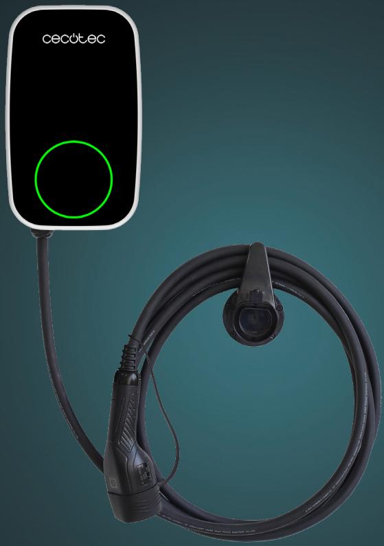
PIT&STOP SMART 11 KW
PIT&STOP SMART 7,4 KW
PIT&STOP SMART 7,4 KW CECOHOME OCPP
Cargador Residencial / Residential Charger
Safety instructions 9
-
Parts and components 87
-
Before use 88
-
Installation 89
-
Operation 101
-
Wi-Fi connectivity and mobile App 102
-
OCPP Smart Home Connection 103
-
Cleaning and maintenance 103
-
Troubleshooting 104
-
Recycling of electrical and electronic equipment 104
-
Copyright 105
-
Information on data stored by connected products in accordance with Regulation (EU) 2023/2854 ("Data Regulation") 105
-
EU Declaration of Conformity 105
SOMMAIRE
EN • The coding in this manual is generic and applies to all code variants of the appliance.
Read the following instructions carefully before using the appliance. Keep this instruction manual for future reference or new users.
- This instruction manual contains important instructions that must be followed during installation, operation and maintenance of the appliance. When using electrical appliances, observe the following safety warnings and precautions.
- Only qualified personnel should carry out installation and adjustments. To minimise the risk of electric shock, avoid performing maintenance or repair work that is not specified in the operation instructions unless you are properly prepared.
- For electrical work, make sure to follow the local and national rules and regulations regarding electrical connections as well as these installation instructions. The mains connection must comply with national regulations for electrical installations.
Risk of electric shock and fire
- Do not install or use the charger near flammable, explosive or combustible gases, materials or chemicals.
- Disconnect the power circuit breaker before installing, servicing or cleaning the charger.
Warning:
- This appliance contains chemicals that have been classified as carcinogenic. Direct exposure to these toxic agents constitutes an attributable cancer risk.
- Keep an eye on the appliance at all times during use if children are nearby.
- The charger must be earthed by means of a permanent wiring system or an insulated conductor.
- Use the charger in accordance with the operating parameters indicated in the technical specifications.
- Do not pour water or any other liquid directly onto the charging station. Do not pour water over the charging connector or immerse it in any other liquid. Whenever you finish a charging session, place the charging connector in the bracket to avoid unnecessary exposure to dirt or moisture.
- Do not use the charger if it is defective, cracked, worn, broken, damaged or malfunctioning.
- Do not use the charger if the charging cable is defective, broken, damaged or not working properly.
- Do not try do disassemble, handle, modify, or repair the appliance. This appliance contains no user serviceable parts. For any repairs or modifications, contact the official Cecotec Technical Support Service.
-
Use caution when transporting this appliance. Be sure to route the charging cable in a safe place where it will not be stepped on, pinched or tripped over, damaged or subjected to excessive force.
-
Do not insert fingers or metal objects such as cables, tools or pins inside the charging connector port. Do not insert fingers or other foreign objects into any other part of the appliance.
- Do not bend or crush the charging cable. Do not run the cable over sharp surfaces.
- The use of this appliance may affect the operation of implantable electronic medical devices such as pacemakers or cardioverter defibrillators. Before using this appliance, consult the manufacturer regarding the effect of charging on such electronic devices.
Precautions
- Do not use private electric generators as a power source for charging.
- The operating temperature range of the charging station is between -30 °C and 50 °C, do not use it outside this range.
- Avoid using the charger if it has been directly exposed to heavy rain.
- If the charging cable shows damage or the charger housing is broken, do not use the device and contact Cecotec's official Technical Support Service.
- When using the appliance, make sure that the charging connector is correctly plugged into the vehicle's socket. If the LED indicator light lights up green, then the charging cable is properly connected to the vehicle.
- The charger is an electrical appliance; do not allow children to handle or play with the charger, whether it is operating or not.
- Avoid exposing the charging cable to rain when charging the vehicle to prevent damage to the cable.
-
Touching unprotected metallic conductors when servicing the appliance may result in a risk of electric shock.
-
Prevent the charging cable from twisting or kinking during charging. Do not drag the cable on the floor to prevent damage to the cable.
- Once charging is complete, disconnect the charging cable from the vehicle's charging port and place it in the charging station holder. Do not drop the charging cable on the ground, as this could damage it.
- Incorrect installation and testing can damage both the vehicle's battery and its electronic components, as well as the AC charging station itself. Any damage caused as a result will not be covered by the warranty.
- This appliance can be used both indoors and outdoors.
- The installation of the AC charging station must be carried out by qualified electricians.
- Disconnect the circuit breaker of the electric vehicle charging station before carrying out any installation or work on the charging station.
Power supply input characteristics
- The EV charging station is intended to be connected to AC mains.
- The EV charging station is intended to be plugged and wired and permanently connected.
Power supply outlet characteristics
- The type of current supplied by the EV charging station is EV AC.
Normal environmental conditions
- This appliance can be used both indoors and outdoors.
Access
- EV charging station is intended for use in locations with unrestricted access.
Method of assembly
- The EV charging station is stationary and intended for surface built-in installation.
Protection against electric shock
- The equipment protection against electric shock is class I.
Charging modes
- EV charging station shall be classified according to mode 2.
- The degree of protection against mechanical impact is IK10.
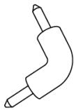
- The use of external adapters is not allowed.
INSTRUCTIONS DE SÉCURITÉ

Fig. 2
Nota:
1
2
3

4

5
6

7

8
Fig. 4
Figura 4:
Fig. 5
Advertencias
Fig. 6
Diámetros orientativos del orificio inferior: ∅24 mm (modelo monofásico EU01_116898 - PIT&STOP SMART 7,4 kW) o ∅28 mm (modelo trifásico EU01_116897 - PIT&STOP SMART 11 kW).
Fig. 7

Fig. 9
Modelos admitidos:
- Monofásico AC 220–240 V, 50/60 Hz (referencia EU01_116898 - PIT&STOP SMART 7,4 kW).
- Trifásico AC 380–415 V, 50/60 Hz (referencia EU01_116897 - PIT&STOP SMART 11 kW).
Fig. 11
- Fijación a pared:

Fig. 12
Fig. 13
Fig. 14
Fig. 15
Fig. 16
Tuck the Sealing rubber into the housing from the outside in. Insert it with angle level, allowing its seal groove to fit into the housing.
Fig. 17

Fig. 18
A01 EU01 116897
| DIP switch position | ||
| Current(A) | 16 | 10 |
| Min. wire size (copper) | 2.5mm 2 or 13AWG | 1.5mm 2 or 15AWG |
| Circuit breaker (Amps) | 20 | 16 |
| DIP switch position | ||
| Earth check | Yes | No |
A01 EU01 116898
| DIP switch position | ||||
| Current(A) | 32 | 16 | 13 | 10 |
| Min. wire size (copper) | 6mm 2 or 10AWG | 2.5mm 2 or 13AWG | 2mm 2 or 14AWG | 1.5mm 2 or 15AWG |
| Circuit breaker (Amps) | 40 | 20 | 20 | 16 |
| DIP switch position | ||||
| Earth check | Yes | No | ||
Fig. 19
https://cecotec.es/es/information/declaration-of-conformity
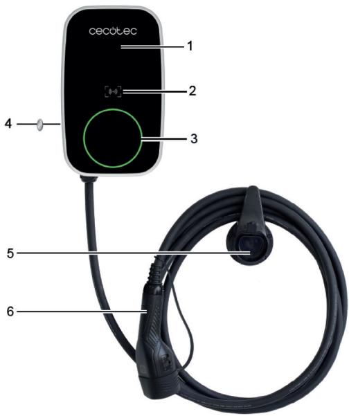
1. PARTS AND COMPONENTS
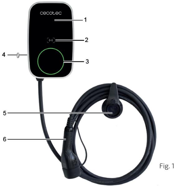
Figure 1:
- Front cover
- RFID area
- Operating indicator light
- Function button
- Charger holder
- Charging cable and connector
ENGLISH
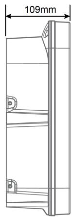
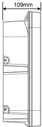
Figure 2 shows the product dimensions.


Fig. 2
Note:
The graphics in this manual are schematic representations and may not exactly match the product.
2. BEFORE USE
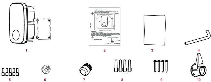
Fig. 3
| Item | Quantity | Comments | |
| 1 | Charger and mounting bracket | 1 unit of each | They are factory assembled and are separated during installation. |
| 2 | Installation template | 1 | To mark the fixing points on the wall. |
| 3 | Instruction manual | 1 | — |
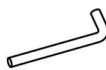
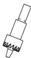
| 4 | Angled Allen wrench | 1 | For fixing/assembling the mounting bracket. |
| 5 | Wiring plugs | — | Quantity not specified in the original. |
| 6 | Sealing rubber | 1 | Sealing gasket for cable passage or closure. |
| 7 | Cable gland | 1 | For sealing the power cable. |
| 8 | Wall plugs M6×30 | 4 | For wall mounting (material to be confirmed). |
| 9 | ST4.2×32 screws | 4 | For fixing the mounting bracket. |
| 10 | Charger holder | 1 | Intended for connector and charging cable only. |
- Do not remove the product's serial number in order to keep proper traceability if technical assistance is required.
3. INSTALLATION
Tools and materials required (not included)

Fig. 4
ENGLISH
Figure 4:
- Electric drill: for drilling anchorages and cable glands.
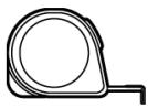
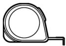
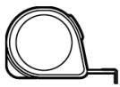
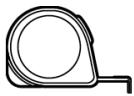
- Tape measure: to measure heights and distances.
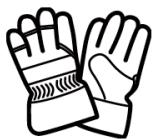
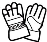
- Protective gloves: for safe handling and drilling.
- Power angle tool: angled accessory for drilling in confined spaces.
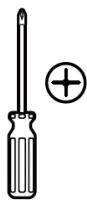
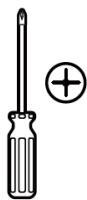
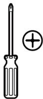
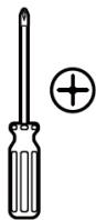
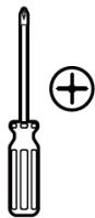
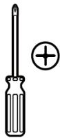
- Cross screwdriver.
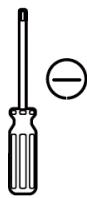
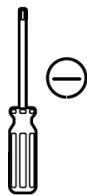
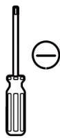
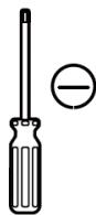
- Flat-head screwdriver.
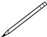
- Pencil: to mark template and drilling points.
-
Crown saws:
-
Mode 1 (bottom hole):
- ∅24 mm: for single-phase model EU01_116898 - PIT&STOP SMART 7.4 kW.
- ∅28 mm: for three-phase model EU01_116897 - PIT&STOP SMART 11 kW.
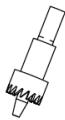
- Mode 2 (rear hole): - ∅18 mm: for the sealing rubber (rear hole).
Before installation
- Read and understand the entire contents of the manual before installing or using the unit.
- Choose a suitable location according to the installation conditions indicated in the warnings.
- Ensure that the installation site complies with current regulations.
- Confirm that there is a power supply at the point of installation with the appropriate voltage and type of mains supply, consistent with the power rating of the product.
- Verify that the fasteners supplied are suitable for the surface. If they are not, they should be replaced with suitable alternatives before proceeding.
Installation location
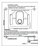
- Maintain clearance around the unit for installation and future maintenance.
- Recommendation: minimum lateral clearance of 250 mm on each side. Fig. 5.
- Reserve a space for the charger holder (for the connector and cable).
Warnings:
- Turn off the power supply before installing the unit.
- The manufacturer and distributors are not responsible for loss or damage caused by improper installation.
- The installer shall be responsible for damage to the product, system or property resulting from improper installation.
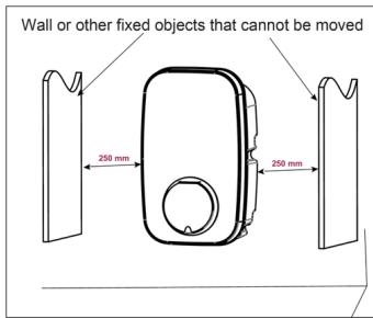
Fig. 5
Important: Before installing the unit, it is necessary to confirm the method of power supply cable entry for the product. Cable entry via option 3 is strictly prohibited.
- Option 1: Bottom entry (recommended): the cable enters through the bottom and is sealed with the cable gland. Fig. 6.
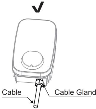
Fig. 6
○ Indicative diameters for the bottom hole: ∅24 mm (single-phase model EU01_116898 - PIT&STOP SMART 7.4 kW) or ∅28 mm (three-phase model EU01_116897 - PIT&STOP SMART 11 kW).

Fig. 7
- Option 2: Rear entry: the cable enters through the rear, using the sealing rubber. Fig. 7 - Indicative diameter for the rear hole: ∅18 mm (for the sealing rubber).
WARNING: it is strictly forbidden to pass a cable entering from the bottom to the rear. Do not perform this routing in any case. Fig. 8

Fig. 8
After cable routing, ensure sealing by properly tightening the cable gland or fitting the sealing rubber.
Electrical wiring connection
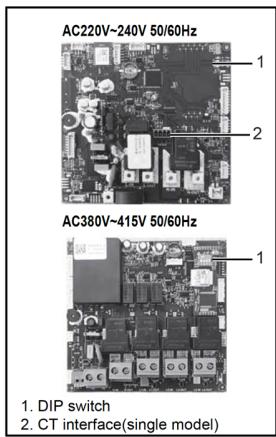


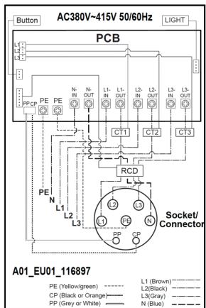
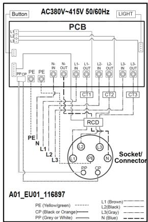
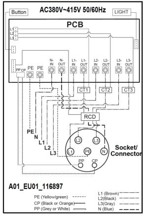
Fig. 9
Supported models:
- Single-phase AC 220-240 V, 50/60 Hz (reference EU01_116898 - PIT&STOP SMART 7.4 kW).
- Three-phase AC 380-415 V, 50/60 Hz (reference EU01_116897 - PIT&STOP SMART 11 kW).
Relevant components (according to diagrams):
- Function button, Operating indicator light (LIGHT), Electronic board (PCB), Residual current device (RCD), Power management, Terminal block, Socket/Connector (CP/PP/PE/L/N or L1/L2/L3/N/PE).
- DIP switches.
- CT interface (single-phase model).
Connections (according to diagram):
- Single-phase: connect L, N and PE to the terminal block. The socket/connector conductors are identified as CP, PP, PE, N and L, with colour coding indicated in the diagram.
- Three-phase: connect L1, L2, L3, N and PE to the terminal block. The socket/connector conductors are identified as PP, PE, N, L1, L2 and L3, with colour coding indicated in the diagram.
External electrical protection (mandatory):
- Miniature circuit breaker (MCB): sized according to the configured maximum output current of the charging point. See current adjustment using DIP switches.
- Residual current circuit breaker (RCCB): according to local regulations, type A or type B.
Installation (internal access and mounting)
- Remove the unit from the mounting bracket and extract the 4 screws that attach it to the mounting bracket. The unit comes integrated with the bracket and must be separated before mounting.
- Remove the 6 screws that join the front cover and rear cover. Keep all screws for later use. Refer to figure 10 as reference (positions "a" and "b").
- Open the front cover carefully: it is attached to the unit's body by a cable. Avoid pulling that could damage this cable.
- Caution: after opening, visually inspect the interior. If the wiring terminal block or an attached component has slipped out of the track, reposition it in the track (see figure 11).
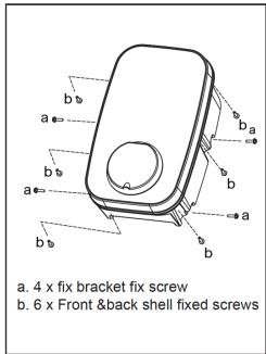
Fig. 10

Fig. 11
- Wall mounting:
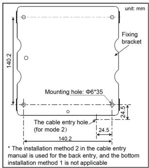
Fig. 12
Use the mounting bracket as a template. Vertical hole spacing: 140 ± 2 mm. Mounting hole: 6 × 35 .
For rear cable entry (referred to as "option 2"), respect the indicated cable passage hole position. Installation with bottom entry ("option 1") does not apply when using rear entry.
Upon completing the wiring, close the front cover ensuring that no cable is trapped and that the sealing points (cable gland or sealing rubber) are correctly seated.
4. Marked with installation template
- Option 1 (bottom entry): use the template to mark the mounting bracket holes.
- Option 2 (rear entry): use the template to mark the mounting bracket holes and the cable entry hole.
Notes:
- In Option 2, pay special attention to the correct orientation of the template.
- Verify that the template is perfectly level before marking.
- Follow the directions printed on the template.
5. Drilling in the wall
- Mounting bracket holes: diameter ∅6 mm and approximate depth 35 mm.
- Option 2 (rear entry): the diameter of the cable passage hole in the wall must match the chosen cable; it is recommended that the maximum diameter does not exceed ∅24 mm.
- Caution: check the edge of the hole in the wall; there must be no sharp edge that could cut the cable.
6. Mounting bracket assembly
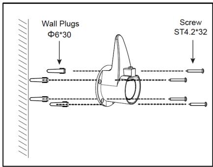
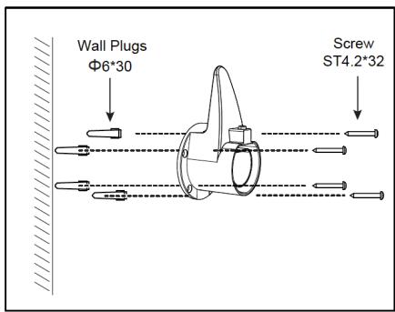
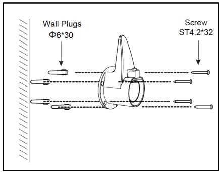
- Insert the wall plugs into the holes and fix the mounting bracket with ST4.2×32 screws. Check that they are firmly tightened.
Note: if the screws are not properly tightened, the bracket could loosen and interfere with the housing installation.
7. Opening the hole in the housing for cable entry:

Fig. 13
- Respect size and position indicated in the figure (reference fig. 13).
- Option 1 (bottom entry): the housing hole diameter is ∅24 mm for the single-phase model (EU01_116898 - PIT&STOP SMART 7.4 kW) or ∅28 mm for the three-phase model (EU01_116897 - PIT&STOP SMART 11 kW). Figure 13 shows reference dimensions 39 mm and 50 mm with respect to the edges.
- Option 2 (rear entry): the housing hole diameter is ∅18 mm.
- Warnings:
o Remove burrs around the bore to avoid compromising the seal.
Do not damage internal components, especially internal wiring, when drilling the hole.
8. Cleaning
- Remove all chips and debris generated by punching/punching from the inside of the housing.
9. Cable entry
- Insert the cable through the corresponding hole (bottom or rear).
- Preparation of the cable end: remove approximately 12 mm of insulation and place the "wiring plug" (Figure 13) or the intended termination before connecting to the terminal block.
- Ensure sealing with the cable gland (bottom entry) or with the sealing rubber (rear entry).
Option 1 (bottom entry with cable gland)
ENGLISH
Cable gland components (see figs. 14–16).
- Pressure head
- Main motor unit
- Built-in sealing ring (internal)
- Sealing gasket/rings ("gasket")
- Nut
Procedure 1:
a1. Verify that all cable gland parts are present and in good condition (fig. 14).

Fig. 14
a2. Pass the gasket and main body through the housing hole and fix them with the nut, as shown in figure 15. Make sure that the built-in gasket does not become dislodged from its housing.

Fig. 15
a3. Insert the pressure head into the cable and then pass the cable through the main body until it is retained (Fig. 16).

Fig. 16
a4. Cut/prepare the cable to the appropriate length, insert the conductors and lock the pressure head to fix the cable and seal the passage.
a5. Connect the cable to the terminal block following the "Electrical wiring connection" section (reference fig. 13). Keep the correspondence of conductors L/N/PE (single phase) or L1/L2/L3/N/PE (three phase).
Note: the connection reference is shown in figure 13.
Warning: to guarantee the declared IP degree of protection, the cable gland included in the accessories must be used and correctly mounted.
a6. Remove from the inside of the housing any chips or debris generated during punching/punching and cable routing.
a7. Check that all cables are connected correctly, tightly and without damage or slack.
a8. Close the front cover and the rear cover by screwing them together with the original screws. Before closing, check that the perimeter gasket in the groove of the Front Cover has not come loose and is properly seated. The closure must ensure IP protection degree.
a9. Screw the unit back onto the mounting bracket using the previously removed screws (reverse operation to that described when disassembling in figure 10).
Procedure 2:
b1. Insert the sealing rubber into the housing from outside to inside (see fig. 17). Pass the conductors through the sealing rubber, using one hole per conductor. After inserting all of them, leave enough cable length to reach the terminal block.
- Note: before installing, prepare the central area of the sealing rubber (by pre-forming its holes) to allow conductor insertion.
b2. Screw the rear cover to the mounting bracket.
- Caution: use the screws removed from their original position.
ENGLISH
b3. Connect the cables to the terminal block following the "Electrical wiring connection" section (reference fig. 13).
b4. Properly seal the rear opening to achieve the IP rating of the equipment.
- Warning: the seal is critical for product safety; visually verify that the sealing rubber is seated around its entire perimeter.
b5. Screw the front cover and the rear cover tightly together.
- Caution: use the original screws. Before mounting the Front Cover, make sure that the perimeter gasket in its groove has not come loose and is correctly positioned.
Final checks
- Make sure that all gaskets and seals are made to achieve the rated IP degree of protection.
- If you do not have a suitable power tool, you can use the included angled Allen key to tighten the cover screws.
Important Note: It is the installer's responsibility to verify that all cable terminations are tight and secure, and that they have not been loosened, overstressed or disconnected during shipping or installa
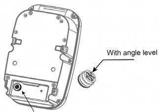
Tuck the Sealing rubber into the housing from the outside in. Insert it with angle level, allowing its seal groove to fit into the housing.
Fig. 17
- After installing the covers, check that there is no visible gap or groove between the front cover and the rear cover.
Charger holder installation
- Remove the charger holder from its packaging.
- Position the charger holder on the wall and mark the four fixing points.
- Drill 4 holes ∅6 mm and 35 mm deep.
- Insert 6×30 wall plugs into the holes.
- Screw the charger holder with ST4.2×32 screws until it is firmly fixed.
-
Installation completed.
-
Choose a location close to the main unit. Recommended height: higher than 0.5 m and not higher than 1.5 m above the ground (0.5 m < height ≤ 1.5 m).
Using the charger holder


Fig. 18
- Connector insertion: when inserting the connector tip into the charger holder you will hear a "click".
- Removal: to remove it, press the locking button and simultaneously pull the connector out.
DIP switch setting (current setting and ground check)
- Important:
o Make any adjustments with the power disconnected.
o Incorrect adjustment may cause overheating or fire of the input cable.
- Only a qualified installer should configure these switches. The set current must never exceed the capacity of the supply or the upstream conductors.
o Factory settings: 32 A in the single-phase model EU01_116898 - PIT&STOP SMART 7.4 kW; 16 A in the three-phase model EU01_116897 - PIT&STOP SMART 11 kW.
- Location:
The DIP switches are on the power supply board. DIP 1 and DIP 2 select the maximum current. DIP 3 enables/disables the ground check.
- Model EU01_116897 - PIT&STOP SMART 11 kW (three-phase 380-415 V):
o Available currents and requirements:
■ 16 A: minimum conductor cross-section (copper) 2.5 mm 4 ( ≈ AWG 13). Recommended circuit breaker: 20 A.
■ 10 A: minimum conductor cross-section (copper) 1.5 mm 2 ( ≈ AWG 15). Recommended circuit breaker: 16 A.
o Ground check (DIP 3):
■ Enabled: "Yes."
■ Disabled: "No."
The exact positions of DIP 1-2 for each current are shown in the manufacturer's schematic attached to this section.
- Model EU01_116898 - PIT&STOP SMART 7.4 kW (single-phase 220-240 V):
o Available currents and requirements:
■ 32 A: minimum conductor cross-section (copper) 6 mm 4 ( ≈ AWG 10). Recommended circuit breaker: 40 A.
16 A: minimum conductor cross-section (copper) 2.5 mm 2 (≈ AWG 13). Recommended circuit breaker: 20 A.
■ 13 A: minimum conductor cross-section (copper) 2 mm 4 (≈ AWG 14). Recommended circuit breaker: 20 A.
■ 10 A: minimum conductor cross-section (copper) 1.5 mm2 (≈ AWG\ 15) . Recommended circuit breaker: 16 A.
o Ground check (DIP 3):
■ Enabled: "Yes."
■ Disabled: "No."
o The exact positions of DIP 1-2 for each current are shown in the following diagram:

Fig. 19
Inspection and commissioning
- Ground check: verify that the unit is properly and continuously grounded.
- Final inspection: confirm that the installation is complete, secure and in safe condition (covers closed, cable gland/rubber sealed, no loose parts).
- Start-up and self-test: energize the equipment. The Operating Status Indicator will cycle red/blue/green (self-test) and then display the corresponding status according to the indicator table.
- Regulatory tests: perform the tests required by current electrical regulations prior to delivery (PE continuity, insulation resistance, earth leakage tests, etc.).
- Make sure that the installation complies with the electrical regulations applicable in your country/region.
4. OPERATION
The charger must be connected to the mains power supply of the house
Circular operating indicator
- Blue, green and red alternating: Self-test on power-up.
- Steady blue light: Standby.
- Flashing blue light: Connector plugged in with the vehicle.
- Steady green light: Charging.
- Flashing green light: Loading stopped from the APP.
- Steady red light: Overtemperature.
- Red light flashing (one fast and one slow flash): Emergency stop.
Function button
The function button is located on the left side of the charger and the following functions can be selected:
| Function | Operation | Status indicator lights | Meaning |
| Emergency stop | During normal charging, press the function button once. | Red light, flashing (one fast and one slow flash). | Disconnect the connector. |
| Reset Wi-Fi | In standby mode, press and hold the function button for more than 10 seconds to reset the Wi-Fi; then re-add the device for pairing. | A beep | The loader must be added again in the application. |
RFID function (only for reference EU01_122639 - PIT&STOP SMART 7.4 kW CecoHome OCPP)
To use the RFID function, you must ensure that the connector is connected to the electric vehicle. In connection confirmation mode, swipe your card in the RFID area of the charger to start charging. When you want to finish, swipe your card again in the RFID area to stop loading. Note: After starting and stopping loading once, swiping the card through the RFID zone will not continue loading. If you wish to continue charging, you must disconnect the connector and reconnect it to the electric vehicle.
CARD REGISTRATION
CONFIGURATION OF THE RFID CARD FOR THE CUSTOMER
In the "Configuration" interface of the application, in the "Enter orders" option, enter the card number that appears on the front of the RFID card: SPEVC########## and then click "Confirm".
ENGLISH
Note: Do not use spaces.
Test it by connecting the vehicle and swiping the card. Loading should begin. If you hear two beeps, it means that the number is incorrect or that there was a space between the period and the comma. If this occurs, you must exit the APP and re-enter to repeat the process.
The two cards supplied have the same number, so it is only necessary to carry out the process with one of them.
5. WI-FI CONNECTIVITY AND MOBILE APP
Scan the following QR code to access the App download option and an instruction manual explaining how to pair your product:

To use the charger through the app on your phone, it must be connected to a Wi-Fi network. It is necessary to select a 2.4 GHz Wi-Fi network (4G), as a 5 GHz network (5G) will not work.
Within the Cecotec App, go to the top right corner and press the "+" icon. Then select the option "Add device".
The device will appear flashing at the top of the application, indicating that it is ready to be paired. Select it to continue with the process and follow the steps shown in the App.
You can also search and add the product manually. Go to the side menu and select the corresponding range and locate the model of your product. Press on it to start the pairing process and connect it to the Wi-Fi network. Follow the steps indicated in the App. Once successfully paired for the first time, it will be stored in your phone.
Once linked, you can access the charger from the application to control its functions, view the charging status, start a new charge, among other options.
NOTE: A Wi-Fi network connection is required. If your phone is connected via mobile data only, the application will not be able to recognize the charger and will not be able to complete the pairing process.
If you are outside the range of a Wi-Fi network, you can share the hotspot from a second phone. This type of connection will be recognised as a Wi-Fi network, allowing the charger to be linked correctly.
6. OCPP SMART HOME CONNECTION (ONLY FOR REFERENCE EU01_122639 - PIT&STOP SMART 7.4KW CECOHOME OCPP)
This charger can be used together with the rest of the devices in a home with home automation technology using the OCCP standard protocol.
7. CLEANING AND MAINTENANCE
- The charger housing does not need to be opened for routine maintenance.
- Periodic cleaning: regularly wipe the external surfaces of the equipment with a slightly damp cloth. To avoid damaging the surface finish, do not use solvents or alcohol and do not clean internal parts.
- Periodic visual inspection: regularly check the exterior of the equipment for damage. If the damage affects safety, isolate the equipment and do not use it until proper repairs have been made.
- Annual electrical inspection: once a year, the charger and the switchgear/protection assembly (if any) must undergo an electrical inspection by a qualified electrician, in accordance with the legislation in force at the place of installation. A record of the tests performed and their results should be kept.
8. TROUBLESHOOTING
| Red light flashing. | Red light status | Meaning |
| Flashing: 1 fast, 2 slow | CP failure (pilot control signal) | |
| Flashing: 2 fast, 1 slow | Overcurrent | |
| Flashing: 3 fast, 1 slow | Leakage current fault | |
| Flashing: 3 fast, 2 slow | Undervoltage | |
| Flashing: 4 fast, 1 slow | Overvoltage | |
| Flashing: 6 fast, 2 slow | Contactor adhesion failure (stuck contacts) | |
| Flashing: 7 fast, 1 slow | Earthing fault | |
| Steady (no flashing) | Overtemperature | |
| Flashing: 3 fast, 3 slow | “Free fault” | |
| Cannot link to a Wi-Fi network. | Ensure that the Wi-Fi network selected on your phone is of the 2.4 GHz type (4G). | |
Note: When a failure occurs, try to remove the connector or cut off the power to reset. If the fault is not eliminated, contact technical service.
9. RECYCLING OF ELECTRICAL AND ELECTRONIC EQUIPMENT

This symbol indicates that, according to the applicable regulations, the product and/or battery must be disposed of separately from household waste. When this product reaches the end of its shelf life, you should dispose of the batteries/accumulators and take them to a collection point designated by the local authorities.
For detailed information on how to properly dispose of electrical and electronic
equipment and/or the corresponding batteries, consumers should contact their local authorities.
Information regarding national packaging recycling systems and their marking can be found on our website.
Compliance with the above guidelines will help protecting the environment.
10. COPYRIGHT
The intellectual property rights over the texts in this manual belong to CECOTEC INNOVACIONES, S.L. All rights reserved. The content of this publication may not, either in part or in its entirety, be reproduced, stored in a retrieval system, transmitted or distributed by any means (electronic, mechanical, photocopying, recording or similar) without prior authorisation from CECOTEC INNOVACIONES, S.L.
11. INFORMATION ON DATA STORED BY CONNECTED PRODUCTS IN ACCORDANCE WITH REGULATION (EU) 2023/2854 ("DATA REGULATION")
Cecotec's connected products and related services are those that generate different data and information during use. In accordance with the provisions of the Data Regulation, through this document Cecotec provides you with information about your rights concerning the data generated and about how to access such data.
This right allows you to use the data for any lawful purpose, including, among others, product and/or service optimisation or contracting post-sale services with third parties.
As a user, you may exercise your right of access, within the limits provided for by the Data Regulation, through the email address data.act@cecotec.es. To protect the generated data—and in order to prevent fraud or identity theft—CECOTEC may require additional information to verify your status as a user.
Data is stored for a determined period of time.
12. EU DECLARATION OF CONFORMITY

Cecotec Innovaciones hereby declares that this residential charging station, model EU01_116897 - PIT&STOP SMART 11 kW; EU01_116898 - PIT&STOP SMART 7.4 kW and EU01_122639 - PIT&STOP SMART 7.4 kW CecoHome OCPP, complies with the Radio Equipment Directive 2014/53/EU.
The full text of the EU Declaration of Conformity can be found on the following website: https://cecotec.es/es/information/declaration-of-conformity
FRANÇAIS
1. PIÈCES ET COMPOSANTS
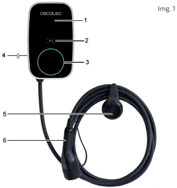
Image 1:
Img. 2
Note :
1
2

3

4

5
6

7

8
Img. 4
Image 4 :
Img. 6

Img. 5
Img. 7

Img. 9
Img. 11
- Montage mural :

Img. 12
Img. 13
Img. 14
Img.15
Img. 16
Img. 17
Installation du support

Img. 18

Abb. 2
Hinweis:
1

2
3

4
5

6

7

8
Abb. 4
Abbildung 4:
Abb. 5
Abb. 6

Abb.9
Abb. 11
- Wandmontage:

Abb. 12
Abb. 14
Abb. 15
Abb. 16
Abb. 17

Abb. 18
A01_EU01_116897
| DIP switch position |  | |
| Current(A) | 16 | 10 |
| Min. wire size (copper) | 2.5mm 2 or 13AWG | 1.5mm 2 or 15AWG |
| Circuit breaker (Amps) | 20 | 16 |
| DIP switch position | ||
| Earth check | Yes | No |
A01_EU01_116898
| DIP switch position | ||||
| Current(A) | 32 | 16 | 13 | 10 |
| Min. wire size (copper) | 6mm 2 or 10AWG | 2.5mm 2 or 13AWG | 2mm 2 or 14AWG | 1.5mm 2 or 15AWG |
| Circuit breaker (Amps) | 40 | 20 | 20 | 16 |
| DIP switch position | ||||
| Earth check | Yes | No | ||
| DIP switch position | ||
| Earth check | Yes | No |
| DIP switch position | ||
| Earth check | Yes | No |
Abb. 19
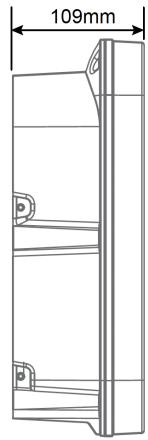
Fig. 2
Nota:
1

2

3
4

5

6

7

8
Fig. 4
Figura 4:
Fig. 5
Fig. 6
Diametri indicativi dei fori inferiori: ∅24 mm (modello monofase EU01_116898 - PIT&STOP SMART 7,4 kW) o ∅28 mm (modello trifase EU01_116897 - PIT&STOP SMART 11 kW).
Fig. 7

Fig. 9
Modelli supportati:
- CA monofase 220-240 V, 50/60 Hz (riferimento EU01_116898 - PIT&STOP SMART 7,4 kW).
- CA trifase 380-415 V, 50/60 Hz (riferimento EU01_116897 - PIT&STOP SMART 11 kW).
ITALIANO
Fig. 11
Fig. 12
Fig. 13
Fig. 14
ITALIANO
Fig. 15
Fig. 16
Tuck the Sealing rubber into the housing from the outside in. Insert it with angle level, allowing its seal groove to fit into the housing.
Fig. 17

Fig 18.
5. CONNETTIVITÀ WI-FI E APP
https://storececotec.it/it/information/declaration-of-conformity
PORTUGUÊS
1. PEÇAS E COMPONENTES
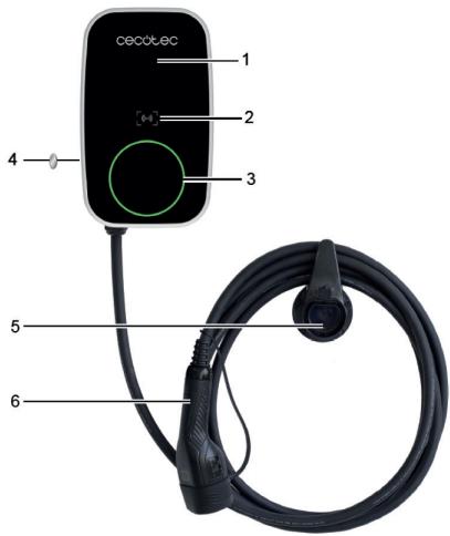
Fig. 1
Figura 1:
Fig. 2

Nota:
1

2

3

4

5

6

7

8
Fig. 4
Figura 4:
Fig. 5
Fig. 6
Fig.7

Fig. 9
Modelos admitidos:
Fig. 11
- Fixação à parede:

Fig. 12
Fig. 13
Fig. 14
Fig. 15
Fig. 16
Tuck the Sealing rubber into the housing from the outside in. Insert it with angle level, allowing its seal groove to fit into the housing.
Fig. 17

Fig. 18
A01_EU01_116897
| DIP switch position | ||
| Current(A) | 16 | 10 |
| Min. wire size (copper) | 2.5mm 2 or 13AWG | 1.5mm 2 or 15AWG |
| Circuit breaker (Amps) | 20 | 16 |
| DIP switch position | ||
| Earth check | Yes | No |
A01_EU01_116898
| DIP switch position | ||||
| Current(A) | 32 | 16 | 13 | 10 |
| Min. wire size (copper) | 6mm 2 or 10AWG | 2.5mm 2 or 13AWG | 2mm 2 or 14AWG | 1.5mm 2 or 15AWG |
| Circuit breaker (Amps) | 40 | 20 | 20 | 16 |
| DIP switch position | ||||
| Earth check | Yes | No | ||
Fig.19
https://cecotec.es/es/information/declaration-of-conformity
1. ONDERDELEN EN COMPONENTEN

Afbeelding 1
Figuur 1:

Afbeelding 2
Opmerking:
1

2

3
4

5

6

7

8

9

10
1

2

3

4

5

6

7
8
Figuur 4:
Afbeelding 5
Afbeelding 6
○ Geschatte diameters van het onderste gat: ∅24 mm (enkelfasig model EU01_116898 - PIT&STOP SMART 7,4 kW) of ∅28 mm (driefasig model EU01_116897 - PIT&STOP SMART 11 kW).
Afbeelding 7
Afbeelding 9
Afbeelding 11
- Wandmontage:

Afbeelding 12
Afbeelding 14
Afbeelding 15
Afbeelding 16
Afbeelding 17

Afbeelding 18
8. PROBLEEMOPLOSSING
https://cecotec.es/es/information/declaration-of-conformity
1. CZĘŚCI I KOMPONENTY
Rysunek 1:
Rys. 2
Uwaga:
1
2

3

4
5

6

7

8
Rysunek 4:
Rys. 5
Rys. 6
Rys. 7

Rys. 9
Obstugiwane modele:
Rys. 11
Rys. 12
Rys. 13
Rys. 14
POLSKI
Rys. 15
Rys. 16
Tuck the Sealing rubber into the housing from the outside in. Insert it with angle level, allowing its seal groove to fit into the housing.
Rys. 17
Rys. 18
A01_EU01_116897
| DIP switch position | 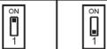 | |
| Current(A) | 16 | 10 |
| Min. wire size (copper) | 2.5mm2 or13AWG | 1.5mm2 or15AWG |
| Circuit breaker (Amps) | 20 | 16 |
| DIP switch position | ||
| Earth check | Yes | No |
A01_EU01_116898
| DIP switch position |  |  | ||
| Current(Å) | 32 | 16 | 13 | 10 |
| Min. wire size (copper) | 6mm 2 or 10AWG | 2.5mm 2 or 13AWG | 2mm 2 or 14AWG | 1.5mm 2 or 15AWG |
| Circuit breaker (Amps) | 40 | 20 | 20 | 16 |
| DIP switch position | ||||
| Earth check | Yes | No | ||
| DIP switch position | ||
| Earth check | Yes | No |
Rys. 18
Kontrola i uruchomienie
Obr. 2

2. PŘED POUŽITÍM
1

5

6
2

7

3

8

9

4

10
Obr. 3
Obr. 5
Obr. 6
Obr. 7

Obr. 9
Přijaté modely:
Obr. 11
- Montáž na stěnu:

Obr. 12
Obr. 13
Obr. 14
ČEŠTINA
Obr. 15
Obr. 16
Tuck the Sealing rubber into the housing from the outside in. Insert it with angle level, allowing its seal groove to fit into the housing.
Obr. 17

Obr. 18
A01_EU01_116897
| DIP switch position | ||
| Current(A) | 16 | 10 |
| Min. wire size (copper) | 2.5mm 2 or 13AWG | 1.5mm 2 or 15AWG |
| Circuit breaker (Amps) | 20 | 16 |
| DIP switch position | ||
| Earth check | Yes | No |
A01_EU01_116898
| DIP switch position | ||||
| Current(A) | 32 | 16 | 13 | 10 |
| Min. wire size (copper) | 6mm 2 or 10AWG | 2.5mm 2 or 13AWG | 2mm 2 or 14AWG | 1.5mm 2 or 15AWG |
| Circuit breaker (Amps) | 40 | 20 | 20 | 16 |
| DIP switch position | ||||
| Earth check | Yes | No | ||
Obr. 19
https://cecotec.es/es/information/declaration-of-conformity
TÜRKÇE
1. PARÇALAR VE BILEŞENLER

Şekil 1:

Not:
1

2

3

4
5

6

7

8
Şekil 4
Şekil 4:
Şekil 5
Şekil 6
Şekil 7

Şekil 9
Kabul edilen modeller:
- Tek fazlı AC 220–240 V, 50/60 Hz (referans EU01_116898 - PIT&STOP SMART 7,4 kW).
- Üç fazlı AC 380–415 V, 50/60 Hz ( referans EU01_116897 - PIT&STOP SMART 11 kW).
Şekil 11
TÜRKÇE
- Duvara montaj:

Şekil 12
Şekil 13
Şekil 14
Şekil 15
Şekil 16
Şekil 17

Şekil 18
- Model EU01_116897 - PIT&STOP SMART 11 kW (üç fazlı 380–415 V):

Σχήμα 2
Σημείωμα:
1
2

3

4
5

6
7

8
Σχήμα 4
Σχήμα 4:
Σχήμα 6
Σχήμα 7
Σχήμα 9
Αποδεκτά μοντέλα:
Σχήμα 11
Σχήμα 12
Σχήμα 13
Σχήμα 14
Σχήμα 15
Σχήμα 16
Σχήμα 17

Σχήμα 18
A01_EU01_116897
| DIP switch position | ||
| Current(A) | 16 | 10 |
| Min. wire size (copper) | 2.5mm 2 or 13AWG | 1.5mm 2 or 15AWG |
| Circuit breaker (Amps) | 20 | 16 |
| DIP switch position | ||
| Earth check | Yes | No |
A01_EU01_116898
| DIP switch position | ||||
| Current(Å) | 32 | 16 | 13 | 10 |
| Min. wire size (copper) | 6mm 2 or 10AWG | 2.5mm 2 or 13AWG | 2mm 2 or 14AWG | 1.5mm 2 or 15AWG |
| Circuit breaker (Amps) | 40 | 20 | 20 | 16 |
| DIP switch position | ||||
| Earth check | Yes | No | ||
https://cecotec.es/es/information/declaration-of-conformity
1. PECES I COMPONENTS
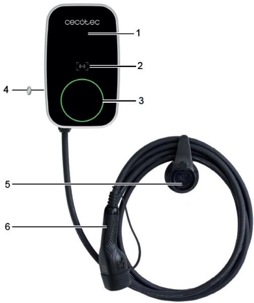
Figura 1:
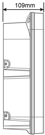
Fig. 2
Nota:
1

2

3

4

5

6

7
8
Fig. 4
Figura 4:
Fig. 5
Fig. 6
Diàmetres orientatius de l'orifici inferior: ∅24 mm (model monofàsic EU01_116898 - PIT&STOP SMART 7,4 kW) o ∅28 mm (model trifàsic EU01_116897 - PIT&STOP SMART 11 kW).
Fig. 7
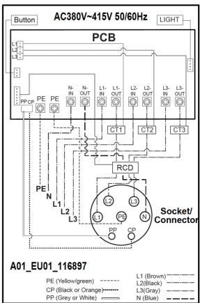
Fig. 9
Models admesos:
Fig. 11
- Fixació a paret:

Fig. 12
Fig. 13
Fig. 14
Fig. 15
Fig. 16
Tuck the Sealing rubber into the housing from the outside in. Insert it with angle level, allowing its seal groove to fit into the housing.
Fig. 17
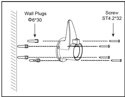
Fig. 18
- ábra

Jegyzet:
1

2

3

4
5
6

7

8
4. ábra
4. ábra:
- ábra
- ábra
- ábra

- ábra
- ábra
- Falra szerelés:

12. ábra
- ábra
- ábra
- ábra
Tuck the Sealing rubber into the housing from the outside in. Insert it with angle level, allowing its seal groove to fit into the housing.
17. ábra
- ábra
A01_EU01_116897
| DIP switch position | ||
| Current(A) | 16 | 10 |
| Min. wire size (copper) | 2.5mm 2 or 13AWG | 1.5mm 2 or 15AWG |
| Circuit breaker (Amps) | 20 | 16 |
| DIP switch position | ||
| Earth check | Yes | No |
A01_EU01_116898
| DIP switch position | ||||
| Current(Å) | 32 | 16 | 13 | 10 |
| Min. wire size (copper) | 6mm 2 or 10AWG | 2.5mm 2 or 13AWG | 2mm 2 or 14AWG | 1.5mm 2 or 15AWG |
| Circuit breaker (Amps) | 40 | 20 | 20 | 16 |
| DIP switch position | ||||
| Earth check | Yes | No | ||
19. ábra
2 الشكل

ملحوظة:
1

2

3

4
5
6

7

8
4 الشكل
الشكل 4
8 الشكل
6 الشكل
الشكل 7
الشكل 9
النماذج المقبولة:
الHMAYA THE KHEPBAYE CHARGY (IZAMY)
11 الشكل
التشبيت على الحائط:
-

12 الشكل
14 الشكل
15 الشكل
16 الشكل
Tuck the Sealing rubber into the housing from the outside in. Insert it with angle level, allowing its seal groove to fit into the housing.
17 الشكل
تركيب حامل الشاحن
18 الشكل
استخدام حامل الشاحن
A01_EU01_116897
| DIP switch position | ||
| Current(A) | 16 | 10 |
| Min. wire size (copper) | 2.5mm 2 or 13AWG | 1.5mm 2 or 15AWG |
| Circuit breaker (Amps) | 20 | 16 |
| DIP switch position | ||
| Earth check | Yes | No |
A01_EU01_116898
| DIP switch position |  |  | [725B] |  |
| Current(A) | 32 | 16 | 13 | 10 |
| Min. wire size (copper) | 6mm 2 or 10AWG | 2.5mm 2 or 13AWG | 2mm 2 or 14AWG | 1.5mm 2 or 15AWG |
| Circuit breaker (Amps) | 40 | 20 | 20 | 16 |
| DIP switch position | ||||
| Earth check | Yes | No | ||
| DIP switch position | [KHGO] |  |  | [SHXA] |
| Earth check | Yes | No | ||
19 الشكل
ال Confidence والTeslaغيل


- SOMMAIRE
- RISK OF ELECTRIC SHOCK AND FIRE
- WARNING
- PRECAUTIONS
- POWER SUPPLY INPUT CHARACTERISTICS
- POWER SUPPLY OUTLET CHARACTERISTICS
- NORMAL ENVIRONMENTAL CONDITIONS
- ACCESS
- METHOD OF ASSEMBLY
- PROTECTION AGAINST ELECTRIC SHOCK
- CHARGING MODES
- INSTRUCTIONS DE SÉCURITÉ
- NOTA
- FIGURA 4
- ADVERTENCIAS
- MODELOS ADMITIDOS
- PARTS AND COMPONENTS
- ENGLISH
- BEFORE USE
- INSTALLATION
- TOOLS AND MATERIALS REQUIRED (NOT INCLUDED)
- FIGURE 4
- BEFORE INSTALLATION
- INSTALLATION LOCATION
- WARNINGS
- ELECTRICAL WIRING CONNECTION
- SUPPORTED MODELS
- RELEVANT COMPONENTS (ACCORDING TO DIAGRAMS)
- CONNECTIONS (ACCORDING TO DIAGRAM)
- EXTERNAL ELECTRICAL PROTECTION (MANDATORY)
- INSTALLATION (INTERNAL ACCESS AND MOUNTING)
- MARKED WITH INSTALLATION TEMPLATE
- NOTES
- DRILLING IN THE WALL
- MOUNTING BRACKET ASSEMBLY
- OPENING THE HOLE IN THE HOUSING FOR CABLE ENTRY
- CLEANING
- CABLE ENTRY
- PROCEDURE 1
- PROCEDURE 2
- FINAL CHECKS
- CHARGER HOLDER INSTALLATION
- USING THE CHARGER HOLDER
- DIP SWITCH SETTING (CURRENT SETTING AND GROUND CHECK)
- INSPECTION AND COMMISSIONING
- OPERATION
- CIRCULAR OPERATING INDICATOR
- FUNCTION BUTTON
- RFID FUNCTION (ONLY FOR REFERENCE EU01_122639 - PIT&STOP SMART 7.4 KW CECOHOME OCPP)
- CARD REGISTRATION
- CONFIGURATION OF THE RFID CARD FOR THE CUSTOMER
- WI-FI CONNECTIVITY AND MOBILE APP
- OCPP SMART HOME CONNECTION (ONLY FOR REFERENCE EU01_122639 - PIT&STOP SMART 7.4KW CECOHOME OCPP)
- CLEANING AND MAINTENANCE
- TROUBLESHOOTING
- RECYCLING OF ELECTRICAL AND ELECTRONIC EQUIPMENT
- COPYRIGHT
- INFORMATION ON DATA STORED BY CONNECTED PRODUCTS IN ACCORDANCE WITH REGULATION (EU) 2023/2854 ("DATA REGULATION")
- EU DECLARATION OF CONFORMITY
- FRANÇAIS
- PIÈCES ET COMPOSANTS
- IMAGE 1
- NOTE
- IMAGE 4
- INSTALLATION DU SUPPORT
- ABBILDUNG 4
- MODELLI SUPPORTATI
- ITALIANO
- CONNETTIVITÀ WI-FI E APP
- PORTUGUÊS
- PEÇAS E COMPONENTES
- FIGURA 1
- ONDERDELEN EN COMPONENTEN
- FIGUUR 1
- OPMERKING
- PROBLEEMOPLOSSING
- CZĘŚCI I KOMPONENTY
- RYSUNEK 1
- RYSUNEK 4
- OBSTUGIWANE MODELE
- POLSKI
- KONTROLA I URUCHOMIENIE
- PŘED POUŽITÍM
- PŘIJATÉ MODELY
- ČEŠTINA
- TÜRKÇE
- PARÇALAR VE BILEŞENLER
- ŞEKIL 1
- ŞEKIL 4
- KABUL EDILEN MODELLER
- ŞEKIL 16
- ΣΗΜΕΊΩΜΑ
- ΣΧΉΜΑ 4
- ΑΠΟΔΕΚΤΆ ΜΟΝΤΈΛΑ
- PECES I COMPONENTS
- MODELS ADMESOS
- JEGYZET
- ÁBRA
- 12 الشكل
- 17 الشكل
- 18 الشكل
- 19 الشكل
Brand : CECOTEC
Model : Pitstop Smart 11 Kw
Category : Washing machine