
HC60NG - Thermostat HONEYWELL - Free user manual and instructions
Find the device manual for free HC60NG HONEYWELL in PDF.
| Brand | HONEYWELL |
| Model | HC60NG (relay module) / HCW80 (thermostat) |
| Product type | Wireless room thermostat with relay module |
| Module power supply | 230 V~, 50 Hz |
| Thermostat power supply | 2 AA 1.5 V LR06 batteries |
| Radio frequency | 868.0–868.6 MHz |
| Radio range | 30 m in a residential dwelling |
| Protection rating | IP30 (module and thermostat) |
| Module operating temperature | 0 to 40 °C (relay <8 A) / 0 to 30 °C (relay >8 A) |
| Thermostat operating temperature | 0 to 50 °C |
| Storage temperature | Module: -20 to 55 °C; Thermostat: -20 to 70 °C |
| Humidity | Module: 0 to 90 % RH; Thermostat: 5 to 90 % RH |
| Configuration | Pre-configured kit Y6630D1007 (paired thermostat and module) |
| Main functions | Intelligent temperature control, test mode, setting range limitation, frost protection (5 °C) |
| Settings | Minimum switch-on time: 1 minute; Cycles: 6 cycles/hour |
| Relay contacts | Potential-free changeover SPDT, 24–230 V~, 10 A resistive |
| Visual indication | Red light on module and thermostat |
| Installation | By a qualified installer; in compliance with applicable standards |
| Maintenance | Replace batteries when the red light on the thermostat flashes; clean with a soft dry cloth |
| Safety | Electrostatic discharges, humidity, risk of electric shock |
| Standards | EN 60730-1, EN 55014-1, EN 55014-2, ETSI EN 300 220-3, ETSI EN 301 489-3 |
| WEEE directive | Do not dispose of with household waste; recycle at an approved center |
Frequently Asked Questions - HC60NG HONEYWELL
User questions about HC60NG HONEYWELL
0 question about this device. Answer the ones you know or ask your own.
Ask a new question about this device
Download the instructions for your Thermostat in PDF format for free! Find your manual HC60NG - HONEYWELL and take your electronic device back in hand. On this page are published all the documents necessary for the use of your device. HC60NG by HONEYWELL.
USER MANUAL HC60NG HONEYWELL
Wireless Room Thermostat
Installation and Operation
Drahtloser Raumthermostat
- General safety instructions 5
1.1. Commissioning the relay module HC60NG.....5 - Overview 6
2.1. Pre configured kit Y6630D1007 6
2.2. Singly provided devices 6 - Installation 6
3.1. Installation relay module HC60NG 6
3.1.1. Connections for R6660D and HC60NG 7
3.2. Installation room unit HCW 80 8 - Checking 9
4.1. System check 9
4.2. Radio transmission check 9 - Teach-in (singly provided devices only) 9
5.1. Assignment to the relay module HC60NG 9
5.2. Failed teach-in 9 - Communication loss 9
- Factory reset of relay module HC60NG 9
- Particular features of the room unit HCW 80.....10
8.1. Operation 10
8.2. Limiting the adjustment range 10
8.3. Fixed control parameters 10 - Changing batteries 10
- Appendix 11
10.1. Help with problems 11
10.2. Specifications HCW 80 11
10.3. Specifications HC60NG 11
10.4. Device and function definition in accordance with EN 60730-1. 11
10.5. WEEE directive 2002/96/EC – Waste Electrical and Electronic Equipment directive 11
1. General safety instructions
1.1. Commissioning the relay module HC60NG
DANGER

Danger to life due to electric shock! Contacts that are open are live.
Ensure that the device is de-energised.
Have all the work carried out by authorised qualified personnel.
Observe the valid local regulations during the installation.
WARNING

Insufficient data transfer!
Interference of the relay module HC60NG in the device due to metallic objects or further frequency devices.
Mount the device with a distance of at least 30~cm to metallic objects such as wall boxes or boiler housings according to the DECT standard, etc.
Do not mount on metal wall boxes.
WARNING

Damage to the device!
Short-circuiting due to humidity and moisture.
Mount the device at a site that is protected against humidity and moisture.
WARNING

Damage to exposed components!
Destruction of the electronic components due to electrostatic discharges.
Do not touch the components.
- Touch an earthed piece of metal to discharge static electricity from your body.
2. Overview
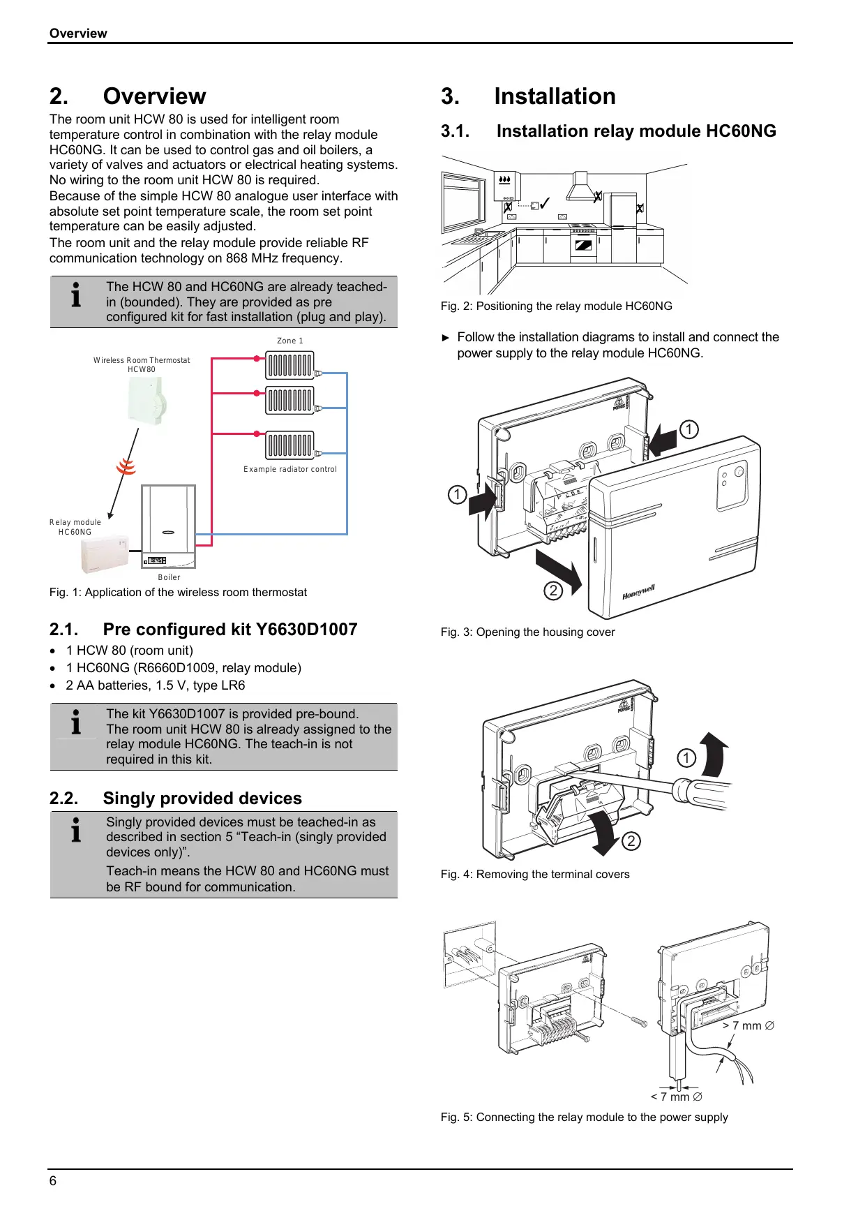
The room unit HCW 80 is used for intelligent room temperature control in combination with the relay module HC60NG. It can be used to control gas and oil boilers, a variety of valves and actuators or electrical heating systems. No wiring to the room unit HCW 80 is required. Because of the simple HCW 80 analogue user interface with absolute set point temperature scale, the room set point temperature can be easily adjusted.
The room unit and the relay module provide reliable RF communication technology on 868 MHz frequency.

The HCW 80 and HC60NG are already teachedin (bounded). They are provided as preconfigured kit for fast installation (plug and play).
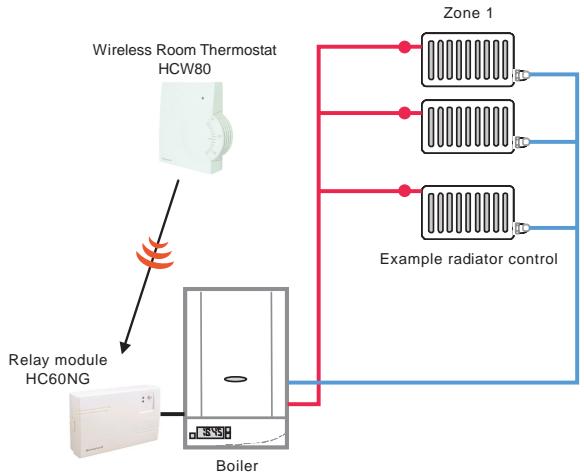
Fig. 1: Application of the wireless room thermostat
2.1. Pre configured kit Y6630D1007
1 HCW 80 (room unit)
1 HC60NG (R6660D1009, relay module)
2 AA batteries, 1.5 V, type LR6

The kit Y6630D1007 is provided pre-bound.
The room unit HCW 80 is already assigned to the relay module HC60NG. The teach-in is not required in this kit.
2.2. Singly provided devices

Singly provided devices must be teach-in as described in section 5 "Teach-in (singly provided devices only)".
Teach-in means the HCW 80 and HC60NG must be RF bound for communication.
3. Installation
3.1. Installation relay module HC60NG
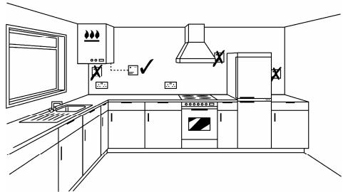
Fig. 2: Positioning the relay module HC60NG
- Follow the installation diagrams to install and connect the power supply to the relay module HC60NG.
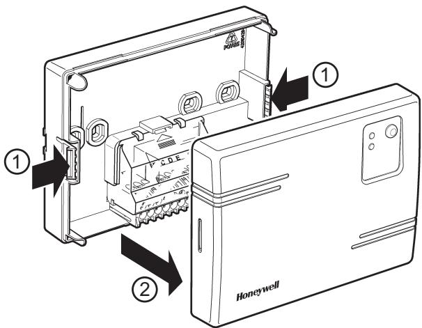
Fig. 3: Opening the housing cover
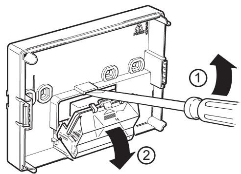
Fig. 4: Removing the terminal covers
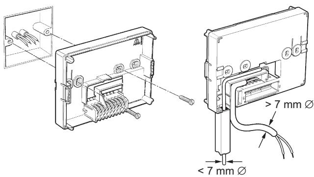
Fig. 5: Connecting the relay module to the power supply
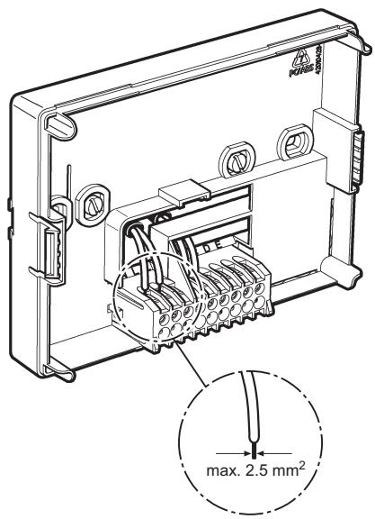
Fig. 6: Wiring the terminal
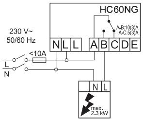
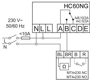
3.1.1. Connections for HC60NG (R6660D1009)

CAUTION
Incorrect wiring!
Install in accordance with local wiring regulations.
Observe ambient temperature and current limits (see HC60NG wiring label).

The green LED on the receiver indicates demand from the thermostat NOT that the heating will be on, this depends on the programmer settings.

CAUTION
Incorrect wiring!
Honeywell accepts no liability for any loss or damage arising from any errors or omissions that may be inadvertently contained within this sketch. This is a proposal sketch only, not a certified wiring diagram.
This diagram must be read in conjunction with any boiler or cylinder manufacturers instructions.
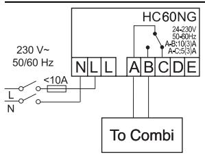
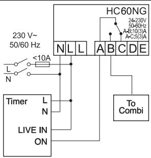
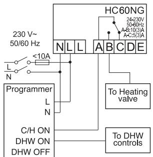
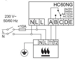
Fig. 7: Wiring diagram for HC60NG
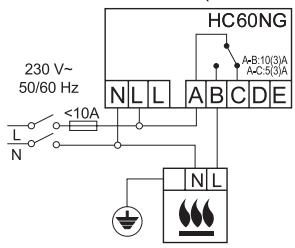
a. Burner (direct control)
b. Combi boiler
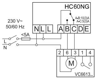
c. Zone valve
d. Electric heater
e. Thermal actuator
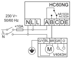
f. Zone valve
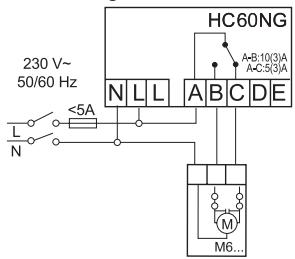
g. Electric actuator
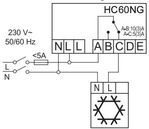
h. Cooling device
Fig. 8: Wiring diagram for HC60NG
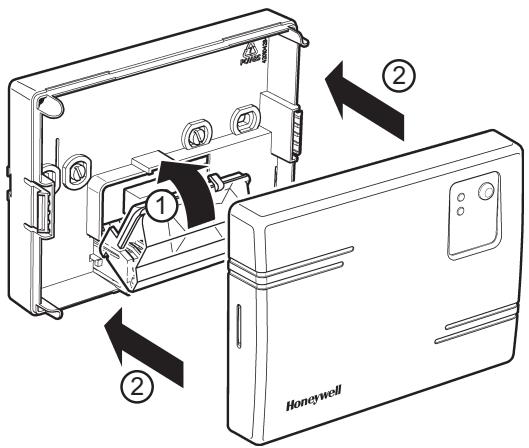
Fig. 9: Closing the terminal and housing cover
3.2. Installation room unit HCW 80

WARNING
Insufficient data transfer!
Interference of the radio receiver in the device due to metallic objects or further radio devices.
Ensure there is sufficient distance to metallic objects.
Mount the device with a distance of at least 1 m to radio devices such as radio headphones, cordless phones according to the DECT standard, etc.
- Select another installation site if the radio interference cannot be corrected.
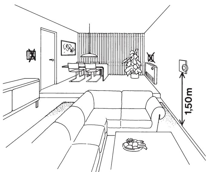
Fig. 10: Positioning the room unit HCW 80
- Place the room unit HCW 80 at the installation site.
- Remove the housing cover of the room unit HCW 80 (see Fig. 11: Removing the housing cover).
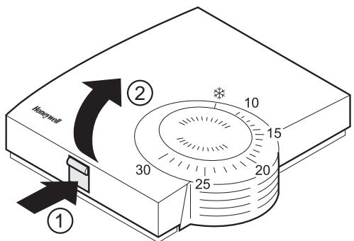
Fig. 11: Removing the housing cover
Mark the drill holes according to the drilling template (see Fig. 12).
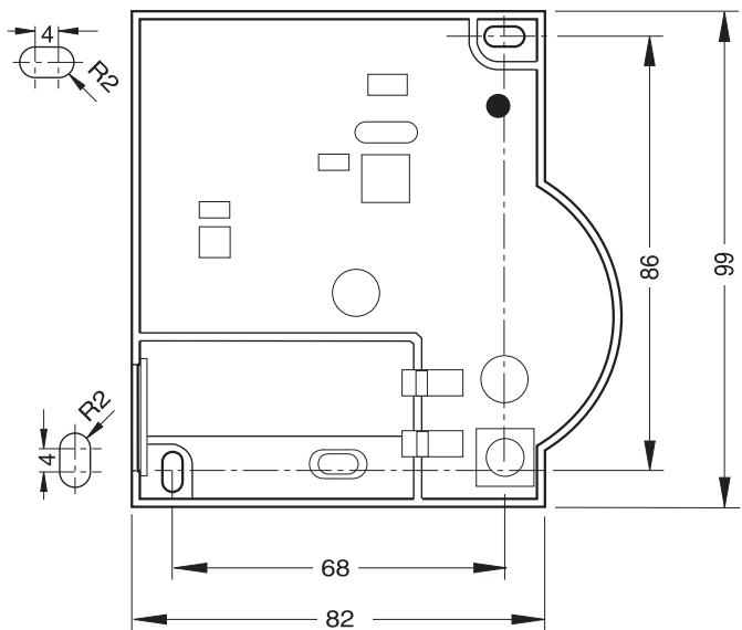
Fig. 12: Drilling scheme (measurements in mm)
Drill the holes.
Screw on the room unit.
- Insert the supplied AA batteries with the correct battery polarity (see Fig. 13: Battery polarity and send button).
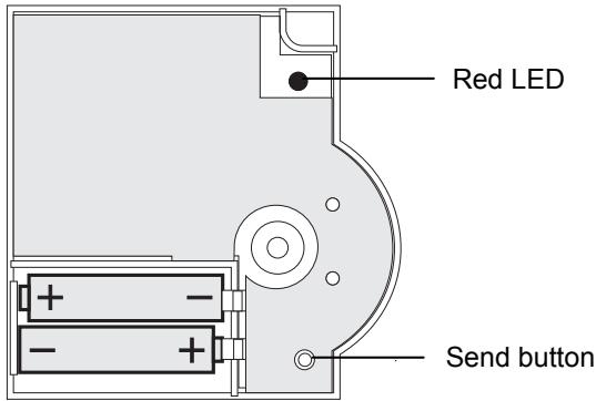
Fig. 13: Battery polarity and send button
The batteries have to be replaced when the red LED at the room unit HCW 80 flashes (see section 9 "Changing batteries").
- Place the housing cover in position above and snap it down (see Fig. 14).
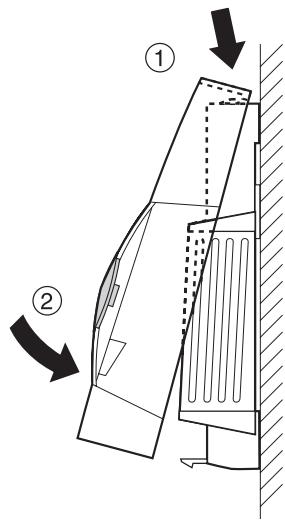
Fig. 14: Placing housing cover in position
4. Checking
4.1. System check
Adjust the set point of the room unit HCW 80 to 30^
If the room temperature is >30^ the relay module HC60NG is switched on.
Change the set point of the room unit HCW 80 to 5^
If the room temperature is < 5^ the relay module HC60NG is switched OFF.
4.2. Radio transmission check
The room unit HCW 80 can send a test signal to the assigned relay module HC60NG in order to test the signal strength.
- Keep the teach-in button of the HCW 80 pressed for at least 15 sec until the red LED of the HCW 80 is OFF.
The HCW 80 is now in test mode and sends a test signal every 5 sec.
The LED of the HCW 80 flashes briefly at every test signal the HCW 80 is sending.
The field strength is indicated by flashing of the red LED of the HC60NG (1 = sufficient, 5 = strong).
If the wireless communication is not successful optimise the placement of the HCW 80.
i
The test mode is terminated automatically after 5 min. The test mode can also be terminated by removing the batteries or by pressing the teach-in button.
5. Teach-in (singly provided devices only)
The teach-in operation is required if the relay module HC60NG and the room unit HCW 80 are not pre-bound e.g. new single devices or product replacement.
5.1. Assignment to the relay module HC60NG
After the power up of the relay module HC60NG the red LED will start to flash at 0.1 sec ON / 0.9 sec OFF.
If this is not the case set the HC60NG into the reset mode see section 7 "Factory reset of relay module HC60NG".
Press and hold the teach-in button of the HC60NG for 5 sec to enter into the teach-in mode.
The red LED flashing at 0.5 sec ON / 0.5 sec OFF confirms the teach-in mode has been entered.
Press the teach-in button of the HCW 80 to send the binding signal to the HC60NG.
The red LED of the HC60NG is switched OFF to confirm a successful teach-in operation.
The teach-in mode is terminated automatically after 5 min.
5.2. Failed teach-in
If the teach-in has failed:
See section 5.1 "Assignment to the relay module HC60NG".
Improve the data transfer.
Improving the data transfer
- When selecting the operating site of each device ensure that the distance to radio devices such as radio headphones, cordless phones, etc. according to the DECT standard amounts to at least 1m .
- Do not install the devices over metallic wall connecting sockets and at least 30~cm away from the cover of the heat generator.
Correct the installation site of the room unit HCW 80 if necessary.
6. Communication loss
When the RF communication is lost for a period of 1 h, the red LED of the relay module HC60NG is ON to indicate that no RF messages have been received during the last hour. When RF communication is re-established the relay module HC60NG will automatically return to normal operation mode. See chapter 10.1 "Help with problems" for possible cause and problem solving.
7. Factory reset of relay module HC60NG
- Keep the button of the HC60NG pressed for at least 15 sec.
The resetting was successful when the red LED flashes rapidly (1/9 ON/OFF).
i
After the factory reset the HC60NG looses the communication with the HCW 80. See section 5 "Teach-in (singly provided devices only)" for new teach-in.
8. Particular features of the room unit HCW 80
8.1. Operation
The room set point temperature can be set easily at the set point adjuster by means of an adjustment dial. The room set point range is from 10^ to 30^ including the frost protection setting * ( 5^ ).
The HCW 80 simulates a mechanical thermostat by LED indication as follows:
The red LED at the HCW 80 will be switched ON for 4 sec if the deviation between the set point and the room temperature is >1^ . If the deviation is <1^ the red LED is flashing for 4 sec. Respectively the relay module HC60NG will be switched ON or OFF.
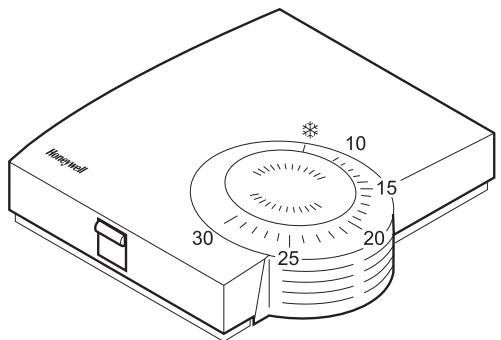
Fig. 15: Room unit HCW 80 (settings on the scale in ^ C )
Select the desired room temperature set point at the adjustment dial (see Fig. 15).
8.2. Limiting the adjustment range
You can limit the adjustment range that can be used at the adjustment dial.
Remove the housing cover (see Fig. 11, Page 8).
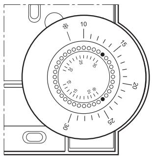
Fig. 16: Limiting the adjustment range
- Place the two small pins into the holes of the adjustment dial in order to limit the adjustment range (see Fig. 16). Orientate yourself on the basis of the inner scale: In Fig. 16, the pins are inserted so that the adjustment dial can only be adjusted in the range of 19^ to frost protection * (lower limit) and 19^ to 30^ (higher limit) around the value 19^ .
Turn the adjustment dial clockwise until it stops. - Check whether the adjustment dial is in the position shown in Fig. 15.
If appropriate, put the adjustment back in, rotated by 180^ until it has the position shown.
Turn the adjustment dial to position 19. - Place the housing cover in position above and snap it down (see Fig. 14, Page 8).
8.3. Fixed control parameters
The following parameters will be used for the control:
| Parameter | Factory setting | Remark |
| Minimum ON time | 1 minute | Minimum power up time within the cycle |
| Cycle rate | 6 cycles per hour | Pulse width modulation per hour |
9. Changing batteries
Change the batteries if the red LED of the room unit HCW 80 flashes and the device is not in test mode.
Remove the housing cover of the HCW 80 (see Fig. 11, Page 8).
Remove the batteries.

Dispose of the batteries according to the local statutory requirements and not with the domestic refuse.

Always replace both batteries together. Only use 1.5V batteries of the type LR06, AA.
Insert the batteries with the correct polarity into the battery compartment (see Fig. 13, Page 8).
- Place the housing cover on at the top and latch it in downwards (see Fig. 14, Page 8).
10. Appendix
10.1. Help with problems
| Problem | Cause | Remedy |
| Teach-in failed | Batteries inserted incorrectly | Insert the batteries correctly. |
| Radio connection failure | Eliminate interference sources (metal, wireless devices). Correct installation site. Repeat the teach-in. | |
| HC60NG does not react to set point changes on HCW 80 | HC60NG and HCW 80 not taught-in | Reset HC60NG. Follow the teach-in procedure as described in section 5. |
| After teach-in red LED is on and green LED is flashing once every 3 sec | Teach-in procedure incorrect/ incomplete | Repeat the teach-in. |
| Position of HCW 80 incorrect | Repeat the teach-in keeping approx. 1 m distance between HCW 80 and HC60NG. | |
| Red LED of the HC60NG is on | Communication loss | Relocate the HCW 80 (see section 3.2). |
| RF signal blocked | ||
| Batteries of HCW 80 exhausted | Replace batteries in HCW 80 (see section 9). | |
| HC60NG and HCW 80 not taught-in | Follow the teach-in procedure as described in section 5. |
10.2. Specifications HCW 80
| Batteries | 1.5 V, type LR06, AA |
| Frequency | 868.3 MHz (transmitter) |
| Operating temperature | 0 °C to 50 °C |
| Storage temperature | -20 °C to 70 °C |
| Humidity | 5 % to 90 % relative humidity |
| IP class | 30 |
10.3. Specifications HC60NG
| Electrical | |
| Receiver power supply | 230 V AC (+10 %, -15 %), 50 Hz |
| Switch type | SPDT potential free |
| Output rating | 24–230 V AC, 10 A resistive, 3 A inductive, 0.6 p.f. |
| Wire access (receiver only) | From the rear (wall box mounting), right an bottom |
| RF | |
| RF operation band | ISM (868.0–868.6) MHz, 1 % duty cycle |
| RF communication range | 30 m in a residential building environment |
| RF communication technology | Short, high rate transmissions to minimise air time and avoid collisions |
| Blocking immunity | Receiver class 2 (ETSI EN300 220-1 version 1.3.1) |
| RF binding method | Factory pre-bound with the room unit HCW 80 (kit Y6630D1007 only) |
| Environmental & Standard | |
| Operating temperature | 0 to 40 °C when relay load <8 A 0 to 30 °C when relay load >8 A |
| Shipping & storage temperature | -20 to 55 °C |
| Humidity | Humidity range 0 to 90 % rh, non-condensing |
| IP class | 30 |
| Meeting the following standards | EN 60730-1 (1995), EN 55014-1 (1997), EN 55014-2 (1996), ETSI EN 300 220-3 (2000), ETSI EN 301 489-3 (2000) |
10.4. Device and function definition in accordance with EN 60730-1
- Purpose of the device is temperature controlling
Device fulfills protection class 2 - Independently installable electronic control system with fixed installation
- Type of action is type 1.8
- Temperature of ball thrust hardness test for housing components 75^ and for live parts such as, for example, terminals 125^
EMC emitted interference test at 230V 50 HZ maximum - Pollution degree is 2
- Rated voltage is 4000V (corresponding to overvoltage category III)
- Software class is A
10.5. WEEE directive 2002/96/EC - Waste Electrical and Electronic Equipment directive
At the end of the product life dispose of the packaging and product in a corresponding recycling centre.
Do not dispose of the unit with the usual domestic refuse.
Do not burn the product.
Inhaltsverzeichnis
Manufactured for and on behalf of the Environmental and Combustion Controls Division of Honeywell Technologies Sàrl, Ecublens, Route du Bois 37, Switzerland by its Authorized Representative:
Honeywell GmbH
Böblinger Straße 17
71101 Schonaich, Germany
Tel.: (++49) (0) 7031 637 01
Fax: (+ + 49) (0) 7031637493
http://europe.hbc.honeywell.com
The right is reserved to make
modifications
This document is definitive for the enclosed product and replaces all previous publications.
Honeywell Inc. hereby declares that this device complies with the basic requirements and other relevant regulations of guideline 1999/5/EC. The declaration of conformity of the product can be requested from the manufacturer.
Note to non-EU countries: This product may only be used if operation in the 868 MHz frequency band is permissible.