
FN76CS - Thermostat HONEYWELL - Free user manual and instructions
Find the device manual for free FN76CS HONEYWELL in PDF.
| Product type | Fine filter with pressure gauge (without pressure reducer) |
| Brand | HONEYWELL |
| Model | FN76CS |
| Category | Water filter |
| Connection diameters | 3/4", 1", 1 1/4" |
| Max. upstream pressure | 16.0 bar (with translucent filter bowl) |
| Operating pressure | Max. 16 bar / Min. 1.5 bar |
| Max. operating temperature | 40°C |
| Mounting position | Vertical or horizontal, filter bowl downward |
| Housing material | Red brass |
| Screen material | Stainless steel |
| Bowl material | Translucent impact-resistant plastic |
| Filtration technology | Microfilter washable by backwashing |
| Mesh size (filtration fineness) | Lower/upper: 105 / 135 μm |
| Main functions | Water filtration, manual backwash, integrated pressure gauge, visual indication of contamination level |
| Maintenance | Backwash every 2 months (manual or automatic with optional Z11S), clean bowl and seals if necessary |
| Safety | Installation and maintenance by a professional, follow instructions, do not use solvents for cleaning |
| Spare parts available | Filter bowl, replacement screen, seals, pressure gauge, ball valve, etc. |
| Compatible accessories | Automatic backwash Z11S, bronze filter pot FT09RS, check valve RV277 |
| Application | Drinking water (and process water under certain conditions) |
Frequently Asked Questions - FN76CS HONEYWELL
User questions about FN76CS HONEYWELL
0 question about this device. Answer the ones you know or ask your own.
Ask a new question about this device
Download the instructions for your Thermostat in PDF format for free! Find your manual FN76CS - HONEYWELL and take your electronic device back in hand. On this page are published all the documents necessary for the use of your device. FN76CS by HONEYWELL.
USER MANUAL FN76CS HONEYWELL
F76CS/FN76CS/FK76CS/FKN76CS
Einbauanleitung · Installation instructions · Notice de montage
Keep instructions for later use!
- Follow the installation instructions.
- Use the appliance
according to its intended use
in good condition
with due regard to safety and risk of danger. - Note that the appliance is exclusively for use in the applications detailed in these installation instructions. Any other use will not be considered to comply with requirements and would invalidate the warranty.
- Please take note that any assembly, commissioning, servicing and adjustment work may only be carried out by authorized persons.
- Immediately rectify any malfunctions which may influence safety.
2. Functional description
The reverse rinsable filters hold back any dirt particles in the water. These particles are then completely flushed out by reverse rinsing.
Filters with Double Spin Technology have turbine blades which circulate the water and thereby set the rotor on the upper filter into a rotational motion. The internal impeller rinses off particles that have adhered to the upper filter at the intersecting points with the rotor.
The filter combinations (FK76CS and FKN76CS) combine reverse rinsing filter and pressure reducing valve in one appliance.
The integral pressure reducing valve functions on a balanced force principle whereby the force exerted by a diaphragm is balanced against the force of an adjustment spring. The inlet pressure has no influence on opening or closing of the valve. Inlet pressure fluctuation does not therefore affect the outlet pressure.
3. Application
Medium Water
FK76CS / FK76CS:
Inlet pressure Maximum 16.0 bar with clear filter bowl
Outlet pressure 1.5-6.0 bar
F76CS/FN76CS:
Operating pressure Maximum 16.0 bar
The filter is constructed for drinking water installations. In case of a process water application the filter has to be proven individually.
4. Technical data
Installation position Vertical or horizontal, with filter bowl downwards
Operating pressure Minimum 1.5 bar
Operating temperature Maximum 40^ with transparent filter bowl
Connection size 3/4", 1", 11/4"
5. Scope of delivery
The filter combinations FK76CS/FKN76CS comprises:
Housing with pressure gauge
- Spring bonnet with adjustment knob and setting scale
- Valve insert complete with diaphragm and valve seat
- Fine filter in clear filter bowl
- Rotatable connector piece (FK76CS only)
- Ball valve with drain connection
Double ring wrench
The fine filters F76CS/FN76CS comprises:
Housing with pressure gauge
- Fine filter in clear filter bowl
- Rotatable connector piece (F76CS only)
- Ball valve with drain connection
Double wring wrench
6. Options
FK76CS...AA = filter mesh size 100 μm, incl. rotatable connector piece DA74C
FKN76CS-...AA = filter mesh size 100 μm, rotatable connector piece DA74C to be ordered separately - see accessories
F76CS...AA = filter mesh size 100 m , incl. rotatable connector piece DA74C
FN76CS-...AA = filter mesh size 100 m , rotatable connector piece DA74C to be ordered separately - see accessories
7. Assembly
7.1 Installations Guidelines
- Install in horizontal or vertical pipework with filter bowl downwards
o This position ensures optimum filter efficiency
Installshutoffvalves - Ensure good access
- Pressure gauge can be read off easily
- Degree of contamination can be seen with clear filter bowl
o Simplifies maintenance and inspection - Fit immediately after water meter
o Corresponds to DIN 1988, Part 2 - The installation location should be protected against frost
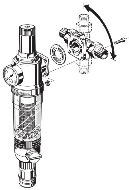
7.2 Assembly instructions
- Thoroughly flush pipework
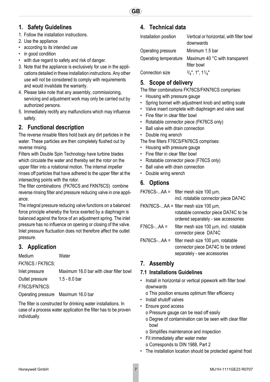
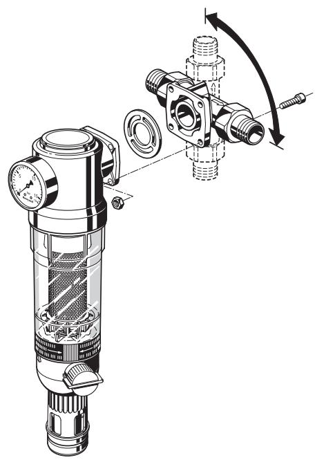
- Install rotatable connector piece
o Note flow direction
o Install without tension or bending stresses

When connecting to an existing flange of another make ensure that the inlet flow is through the outer ring of holes. If this is not so, the whole connection piece must be installed the other way round, even if the arrow does not then indicate the actual flow direction. If the flange is threaded, the threaded holes must be drilled out to a diameter of 6.3mm .
- Install filter to rotatable connector
- Seal in pressure gauge
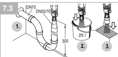
7.3 Discharge of reverse rinsing water
The reverse rinsing water must be routed to the drain channel in such a way that no backwater can occur.
To do this there are 3 options:
- Direct connection:
o Connector DN 50/70 as well as the necessary pipes and siphon (3 elbows 90^ ) in DN 70.
- Drain free to existing floor drain.
- Drain into open container.
Filter size
Reverse rinsing volume*
3/4"
12 litre
1" and 1 1/4"
15 litre
*at 4 bar inlet pressure and 3 × 3 seconds reverse rinsing duration
8. Commissioning
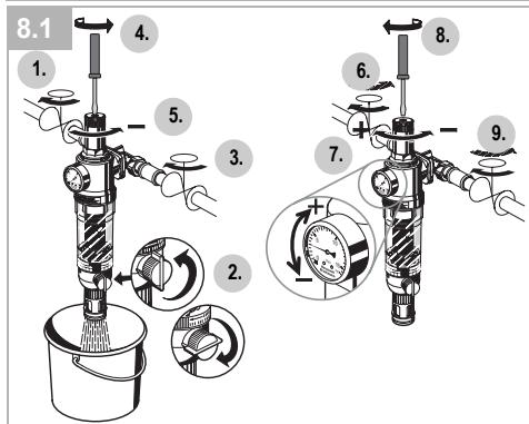
8.1 Setting outlet pressure (only FK76CS/ FKN76CS)

Set outlet pressure min. 1 bar under inlet pressure.
- Close shutoff valve on inlet
- Release pressure on outlet side (e.g. through water tap)
- Close shutoff valve on outlet
- Loosen slotted screw
o Do not remove slotted screw
- Slacken tension in compression spring
o Turn control handle to the left (-) until it does not move any more - Slowly open shutoff valve on inlet
- Turn control handle until the setting scale shows the desired value
- Retighten slotted screw
- Slowly open shutoff valve on outlet
8.2 Reverse rinsing
During reverse rinsing, an inlet pressure of at least 1.5 bar is required. The reverse rinsing interval depends on the degree of dirt in the water. At the latest every 2 months, reverse rinsing should be carried out according to DIN 1988, Part 8. To ensure convenient and regular adherence to the reverse rinsing interval, we recommend installing an automated reverse rinsing system Z11S.

Filtered water can also be tapped during reverse rinsing.
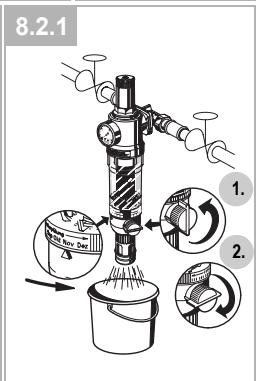
8.2.1 Manual reverse rinsing
If reverse rinsing water is not to be discharged via a direct connection, a collecting container must be positioned beneath before reverse rinsing.
- Open ball valve by turning the reverse rinsing button to the stop point
o Select bar must be upright
o The patented reverse rinsing system starts
o When filtering with Double Spin Technology, a visual function check is possible through the rotating red rotor
- Close ball valve again after approx. 3 seconds. Repeat procedure three times
o If the filter is extremely dirty, the procedure may have to be repeated additional times
With aid of the memory ring, the next deadline for manual reverse rinsing can be booked.
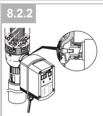
8.2.2 Automatic reverse rinsing with the Z11S
The automated reverse rinsing system Z11S is available as an accessory. The automated system reliably takes over reverse rinsing of the filter at intervals which can be set between 4 minutes and 3 months.
9. Maintenance
We recommend a planned maintenance contract with an installation company
In accordance with DIN 1988, part 8, the following measures must be taken:
9.1 Inspection
9.1.1 Pressure reducing valve(only FK76CS/ FKN76CS)

Interval: once a year
- Close shut off valve on outlet
- Check back pressure using a pressure meter when there is zero through-flow
o If the pressure is increasing slowly, the valve may be dirty or defective. In this instance, carry out servicing and cleaning
- Slowly open shutoff valve on outlet
9.1.2 Filter

Interval: every 2 months
- The filter must be cleaned by reverse rinsing regularly, at the latest every 2 months
Non-compliance can lead to the filter becoming blocked This results in a drop in pressure and decreasing water flow - The filter meshes are made of stainless steel. A red coating as a consequence of rust from the pipelines has no influence on function or the way the filter works
Do not forget to do a visual check of the ball valve. Replace if it is dripping!
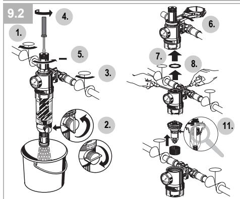
9.2 Servicing
9.2.1 Pressure reducing valve(only FK76CS/ FKN76CS)

Frequency: every 1-3 years (depending on local operating conditions)
To be carried out by an installation company
- Close shutoff valve on inlet
- Release pressure on outlet side (e.g. through water tap)
- Close shutoff valve on outlet
- Loosen slotted screw
o Do not remove slotted screw
Caution!

There is a spring in the spring bonnet. It may cause injuries if the spring is derailing.
-
Make sure tension in compression spring is slakkened!
-
Slacken tension in compression spring
o Turn control handle to the left (-) until it does not move any more
o Do not turn in too far!
- Unscrew spring bonnet
o Use double ring wrench ZR10K
-
Remove slip ring
-
Remove valve insert with a pair of pliers
-
Unscrew filter cup and guide piece o Use double ring wrench ZR10K
10.Remove slotted ring
- Check that sealing ring, edge of nozzle and slotted ring are in good condition, and if necessary replace the entire valve insert
12.Reassemble in reverse order

Press in diaphragm with finger before inserting slip ring
Screw in filter bowl hand-tight (without tools)
- Adjust setting scale and set outlet pressure
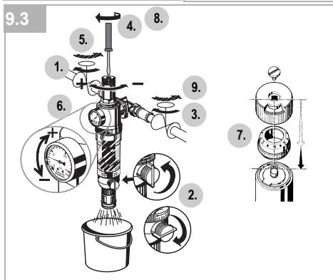
9.3 Adjusting the setting scale(only FK76CS/ FKN76CS)
If the adjustment knob is removed, this setting is lost. A new setting can be achieved using a pressure gauge.
-
Close shutoff valve on inlet
-
Release pressure on outlet side (e.g. through water tap)
- Close shutoff valve on outlet
- Loosen slotted screw o Do not remove slotted screw
- Slowly open shutoff valve on inlet
- Set desired outlet pressure (e.g. 4 bar)
- Align scale (e.g. 4) in middle of viewing window
- Retighten slotted screw
- Slowly open shutoff valve on outlet
9.3.1 Filter

Interval: every 2 months
- The filter must be cleaned by reverse rinsing regularly, at the latest every 2 months
Non-compliance can lead to the filter becoming blocked This results in a drop in pressure and decreasing water flow - The filter meshes are made of stainless steel. A red coating as a consequence of rust from the pipelines has no influence on function or the way the filter works

Do not forget to do a visual check of the ball valve. Replace if it is dripping!
9.4 Cleaning

Caution!
Do not use any cleaning agents containing solvents and/or alcohol to clean the plastic parts!
If necessary, the filter bowl and the filter can be cleaned.

To be carried out by an installation company or the operator.

Detergents must not be allowed to enter the environment or the sewerage system!
- Close shutoff valve on inlet
- Release pressure on outlet side (e.g. through water tap)
- Close shutoff valve on outlet
- Unscrew filter bowl o Use double ring wrench ZR10K
- Remove filter, clean and reinsert
- Place O-ring onto filter bowl
- Screw in filter bowl hand-tight (without tools)
- Slowly open shutoff valve on inlet
- Slowly open shutoff valve on outlet
10. Disposal
Red bronze housing
- Red bronze connector piece
High-quality synthetic material spring bonnet
High-quality synthetic material valve insert
- Stainless steel fine filter
- Shock-resistant, clear transparent synthetic material filter bowl
- Fibre-reinforced NBR diaphragm
NBR seals
11. Troubleshooting
11.1 FK76CS/FKN76CS
| Problem | Cause | Remedy |
| Water is escaping from the spring bonnet | Diaphragm in valve insert is faulty | Replace valve insert |
| Too little or no water pressure | Shutoff valves upstream or downstream from filter not fully open | Open the shutoff valves fully |
| Pressure reducing valve is not set to the desired outlet pressure | Set outlet pressure | |
| Filter mesh dirty | Reverse rinsing | |
| Not fitted in flow direction | Fit filter in flow direction (note direction of arrow on housing) | |
| The outlet pressure set does not remain constant | Filter mesh dirty | Reverse rinsing |
| Valve insert, sealing ring or edge of nozzle is contaminated or worn | Replace valve insert | |
| Rising pressure on outlet (e.g. in boiler) | Check check valve, safety group etc. |
11.2 F76CS/FN76CS
| Problem | Cause | Remedy |
| Too little or no water pressure | Shutoff valves upstream or downstream from filter not fully open | Open the shutoff valves fully |
| Filter mesh dirty | Reverse rinsing | |
| Not fitted in flow direction | Fit filter in flow direction |
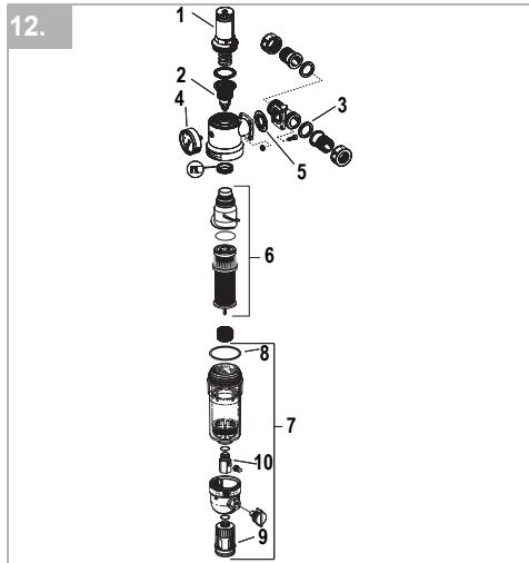
12. Spare Parts
1 Spring bonnet complete 3 / 4^ - 11 / 4^ 0901517 (with setting scale)
2 Valve insert complete 3 / 4 -11/4 D06FA-1A (without sieve)
3 Seal ring set ^3/4 " 0901444 (Pack of 10) 1" 0901445 1^1/4 " 0901446
Pressure gauge M07M-A16 (0-16 bar)
5 Flange seal 3 / 4^ - 1 / 4^ 5536400
6 Filter insert complete for 3 / 4^ - 1^ AF11DS-1A filters with Double Spin Technology Filter mesh 100 m
7 Clear filter bowl 3 / 4^ - 11 / 4^ KF11S-1A complete
8 O-ring set 3 / 4^ - 1^1 / 4^ 0900747 (Pack of 10)
9 Drain connection 3 / 4^ - 1 / 4^ AA76-1/2A
10 Ball valve complete 3 / 4^ - 11 / 4^ KH11S-1A
11 Double ring wrench For removing the filter bowl (no fig.)
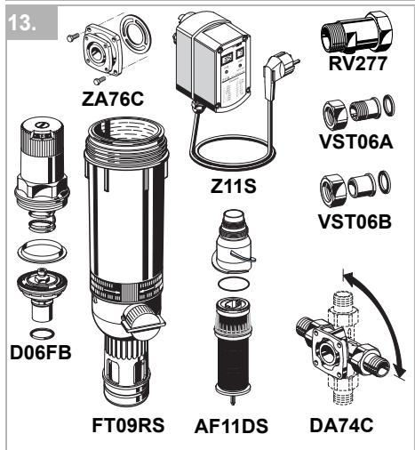
13. Accessories
Z11S Automatic reverse rinsing actuator For automatic filter cleaning at presettable intervals
FT09RS Red-bronze filter bowl For temperatures up to 70^ and operating pressures up to 25.0 bar
ZA76C Connector piece For conversion of the fine filters with rotatable connector pieces (1 1/4" and 1 1/2") into retrofit FKN76CS filter combinations (Converts 63 mm hole centres to 45 mm hole centres)
RV277 Inlet check valve Available in sizes R1 / 2'' - 2''
VST06 Connection set
Connection set
A = Threaded male connection;
B = Solder union connection
AF11DSFilter insert complete Available with filter meshes 100 m for filters with Double Spin Technology
DA74C Rotatable connector piece For connection of retrofit filter combinations
D06FB Retrofit pressure reducing valve For retrofitting to upgrade to a filter combination
Pressionaval 1,5-6,0 bar
F76CS/FN76CS:
Automation and Control Solutions
Honeywell GmbH
Hardhofweg
D-74821 Mosbach
Phone: (49) 6261 810
Fax: (49) 6261 81309
http://europe.hbc.honeywell.com
www.honeywell.com
Manufactured for and on behalf of the
Environmental and Combustion Controls Division of
Honeywell Technologies Sàrl, Ecublens, Route du
Bois 37, Switzerland by its Authorised Representative
Honeywell GmbH
MU1H-1111GE23 R0707
Subject to change
© 2007 Honeywell GmbH
Honeywell
D
- Safety Guidelines 7
- Functional description 7
- Application 7
- Technical data 7
- Scope of delivery 7
- Options 7
- Assembly 7
- Commissioning 8
- Maintenance 8
- Disposal 9
- Troubleshooting 10
- Spare Parts 10
- Accessories 10