
D05 - Pressure regulator HONEYWELL - Free user manual and instructions
Find the device manual for free D05 HONEYWELL in PDF.

User questions about D05 HONEYWELL
0 question about this device. Answer the ones you know or ask your own.
Ask a new question about this device
Download the instructions for your Pressure regulator in PDF format for free! Find your manual D05 - HONEYWELL and take your electronic device back in hand. On this page are published all the documents necessary for the use of your device. D05 by HONEYWELL.
USER MANUAL D05 HONEYWELL
Keep instructions for later use!
Pressure reducing valve
Disconnecteur
Drukreduceerklep
- Follow the installation instructions.
- Use the appliance
according to its intended use - in good condition
with due regard to safety and risk of danger. - Note that the appliance is exclusively for use in the applications detailed in these installation instructions. Any other use will not be considered to comply with requirements and would invalidate the warranty.
- Please take note that any assembly, commissioning, servicing and adjustment work may only be carried out by authorized persons.
- Immediately rectify any malfunctions which may influence safety.
2. Application
Medium Water, compressed air* and nitrogen* in consideration of valid standards (e.g. DIN EN 12502)
Inlet pressure max. 25 bar
Outlet pressure 1.5 - 6 bar
*As part of an installation being approved according to PED requirements, this product must also be certified.
3. Technical data
Operating temperature max. 70^
Minimum pressure drop 1 bar
Connection size 1/2", 3/4", 1"
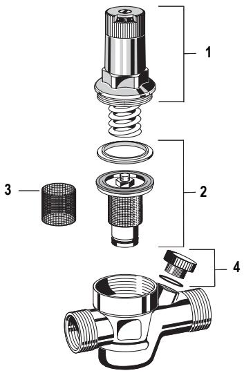
4. Scope of delivery
The pressure reducing valve comprises:
Housing with pressure gauge connection G1/4"
- Threaded connections (option A)
- Valve insert complete with diaphragm and valve seat
- Fine filter with 1 mm mesh
- Spring bonnet with adjustment knob and setting scale
- Adjustment spring
5. Assembly
5.1 Installations Guidelines
It is necessary during installation to follow the installation instructions, to comply with local requirements and to follow the codes of good practice.
Install in horizontal pipework with spring bonnet directed upwards
Installshutoffvalves
- The installation location should be protected against frost and be easily accessible
o Pressure gauge can be read off easily (see accessories)
o Simplified maintenance and cleaning
- For residential applications where maximum protection against dirt is required, install a fine filter upstream of the pressure reducing valve
- Provide a straight section of pipework of at least five times the nominal valve size after the pressure reducing valve (in accordance with DIN 1988, Part 5)
5.2 Installation instruction

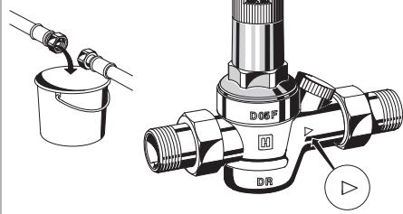
When using soldering connections, do not solder the connections together with the pressure reducing valve! High temperature will irreparably damage important internal working components!
- Thoroughly flush pipework
- Install pressure reducing valve
o Note flow direction
o Install without tension or bending stresses
- Set outlet pressure
6. Commissioning
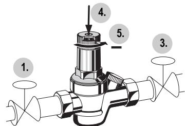
6.1 Setting outlet pressure

Set outlet pressure min. 1 bar under inlet pressure.
- Close shutoff valve on inlet
- Release pressure on outlet side (e.g. through water tap)
- Close shutoff valve on outlet
- Loosen slotted screw
o Do not remove slotted screw
- Slacken tension in compression spring
o Turn control handle to the left (-) until it does not move any more - Slowly open shutoff valve on inlet
- Turn control handle until the setting scale shows the desired value
- Retighten slotted screw
- Slowly open shutoff valve on outlet
7. Maintenance
We recommend a planned maintenance contract with an installation company In accordance with DIN 1988, part 8, the following measures must be taken:
7.1 Inspection
7.1.1 Pressure reducing valve

Interval: once a year
- Close shut off valve on outlet
- Check back pressure using a pressure meter when there is zero through-flow
o If the pressure is increasing slowly, the valve may be dirty or defective. In this instance, carry out servicing and cleaning
- Slowly open shutoff valve on outlet
7.2 Maintenance

Frequency: every 1-3 years (depending on local operating conditions)
To be carried out by an installation company
- Close shutoff valve on inlet
- Release pressure on outlet side (e.g. through water tap)
- Close shutoff valve on outlet
- Loosen slotted screw o Do not remove slotted screw
- Slacken tension in compression spring o Turn control handle to the left (-) until it does not move any more
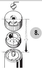
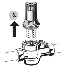
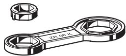
- Unscrew spring bonnet o Use double ring wrench ZR06K
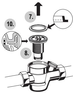
- Remove slip ring
- Remove valve insert with a pair of pliers
- Remove filter and clean
- Check that sealing ring, edge of nozzle and slotted ring are in good condition, and if necessary replace the entire valve insert
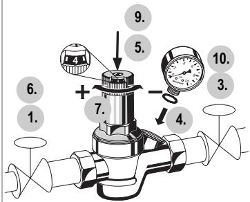
- Reassemble in reverse order
Press in diaphragm with finger before inserting slip ring - Adjust setting scale and set outlet pressure
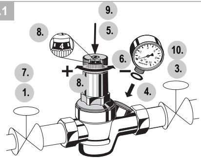
7.3 Adjusting the setting scale
If the adjustment knob is removed, this setting is lost. A new setting can be achieved using a pressure gauge.
- Close shutoff valve on inlet
- Release pressure on outlet side (e.g. through water tap)
- Close shutoff valve on outlet
- Fit manometer
- Loosen slotted screw o Do not remove slotted screw
- Slowly open shutoff valve on inlet
- Set desired outlet pressure (e.g. 4 bar)
- Align scale (e.g. 4) in middle of viewing window
- Retighten slotted screw
- Slowly open shutoff valve on outlet
7.4 Cleaning

Caution!
Do not use any cleaning agents containing solvents and/or alcohol to clean the plastic parts!
If nesseccary, the filter can be cleaned.

To be carried out by an installation company or the operator.

Detergents must not be allowed to enter the environment or the sewerage system!
- Close shutoff valve on inlet
- Release pressure on outlet side (e.g. through water tap)
- Close shutoff valve on outlet
- Slacken tension in compression spring o Turn control handle to the left (-) until it does not move any more
- Unscrew spring bonnet o Use double ring wrench ZR06K
- Remove slip ring
- Remove valve insert with a pair of pliers
- Remove filter, clean and reinsert
- Reassemble in reverse order

Press in diaphragm with finger before inserting slip ring
- Adjust setting scale and set outlet pressure
8. Disposal
- Dezincification resistant brass housing
- Brass threaded connections
High-quality synthetic material valve insert - Stainless steel fine filter mesh
- High-quality synthetic material spring bonnet with adjustment knob and setting scale
Spring steel adjustment spring
- Fibre-reinforced NBR diaphragm
- NBR seals

Observe the local requirements regarding correct waste recycling/disposal!
- Troubleshooting
| Problem | Cause | Remedy |
| Beating sounds | Pressure reducing valve is too large | Call our Technical Customer Services |
| Water is escaping from the spring bonnet | Diaphragm in valve insert is faulty | Replace valve insert |
| Too little or no water pressure | Shutoff valves up- or downstream of the pressure reducing valve are not fully open | Open the shutoff valves fully |
| Pressure reducing valve is not set to the desired outlet pressure | Set outlet pressure | |
| Filter in pressure reducing valve is contaminated | Clean or replace filter | |
| Pressure reducing valve is not fitted in flow direction | Fit pressure reducing valve in flow direction (note direction of arrow on housing) | |
| The outlet pressure set does not remain constant | Filter in pressure reducing valve is contaminated or worn | Clean or replace filter |
| Valve insert, sealing ring or edge of nozzle is contaminated or worn | Replace valve insert | |
| Rising pressure on outlet (e.g. in boiler) | Check check valve, safety group etc. |
10. Spare Parts
No.Description Dimension Part No.
1 Spring bonnet complete 12 - 1" with setting scale
2 Valve insert complete 1/2" - 1" D05FA-1/2B (without filter)
3 Replacement filter insert1/2" - 1" ES05F-1/2A
4 Blanking plug 1/2" - 1" S06K-1/4 with O-ring R1/4" (5 pcs.)
11. Accessories
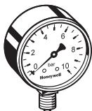
M38K Pressure gauge Housing diameter 50~mm below connection thread G1/4". Ranges: 0 - 4, 0 - 10, 0 - 16 or 0 - 25 bar. Please indicate upper value of pressure range when ordering
ZR06K Double ring wrench For removal of spring bonnet and filter bowl
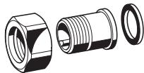
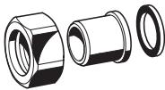
VST06-A Connection set Threaded connections
VST06-B Connection set Solder connections
1/2" - 1" D05FA-1/2B
3 Reservezeef
1/2" - 1" ES05F-1/2A
Automation and Control Solutions
Honeywell GmbH
Hardhofweg
D-74821 Mosbach
Phone: (49) 6261 810
Fax: (49) 6261 81309
http://europe.hbc.honeywell.com
www.honeywell.com
Manufactured for and on behalf of the
Environmental and Combustion Controls Division of
Honeywell Technologies Sàrl, Ecublens, Route du
Bois 37, Switzerland by its Authorised Representative Honeywell GmbH
MU1H-1019GE23 R0208
Subject to change
© 2007 Honeywell GmbH
Honeywell
5.2
6.1
7.2
7.3
10.
11.
M39K
ZR06K
VST06-A
VST06-B
D
- Safety Guidelines 5
- Application 5
- Technical data 5
- Scope of delivery 5
- Assembly 5
- Commissioning 5
- Maintenance 6
- Disposal 7
- Troubleshooting 7
- Spare Parts 7
- Accessories 7