
EX-DGM - Pressure regulator HONEYWELL - Free user manual and instructions
Find the device manual for free EX-DGM HONEYWELL in PDF.

User questions about EX-DGM HONEYWELL
0 question about this device. Answer the ones you know or ask your own.
Ask a new question about this device
Download the instructions for your Pressure regulator in PDF format for free! Find your manual EX-DGM - HONEYWELL and take your electronic device back in hand. On this page are published all the documents necessary for the use of your device. EX-DGM by HONEYWELL.
USER MANUAL EX-DGM HONEYWELL
DWR XXX-203
DWR XXX-205
DWR XXX-206
DWR XXX-213
DWR XXX-513
DWR XXX-574-577
Ex-DWR XXX
$$ R S P = S P + x d $$
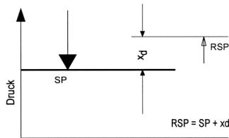
SP = Schaltpunkt
VdTUV pressure 100/1, issue 4.83
VdTUV pressure 100/1, issue 4.83
VdTUV pressure 100/1, issue 4.83
DIN 3398-3 (01.11.1992)
DIN 3398-4 (1986-10)
DGR 97/23 EG
Testing basis (DMG)
DIN 3398-3 (01.11.1982)
- DIN EN 1854 (01.11.1997)
DIN 3398-1 (01.1992) + DIN 3398-3 (11.1982)
Function
Pressure monitor
Pressure limiter (with internal or external interlock)
Action direction
for maximum pressure and minimum pressure monitoring (DWFS, SDBFS)
Type series
DWR Installations acc. to TRD 604
DWR Installations acc. to DIN 4751,
DWR + DGM P.2 DVGW-Worksheet G 260
DWR e.g. fuel oils
Registration No.
ID:000007042
ID: 0000020757
ID:0000020756
NG-4347AQ1411
3C028/5
CE-0035BN0004
Registration No.
NG-4346AP1011
CE-0085AQ1088
Sensor
"Special design" by testing
with 2 million operations


DVGW
TÜV
Type code
| Basic version DWR XXX | Version with additional function DWR XXX-YYY | Ex version Ex-DWR XXX |
| DWR | Identification for series | |
| XXX | Identification for pressure range | |
| YYY | Identification for additional function | |
| Ex- | Identification for Ex version | |
The type code also roughly applies for series DGM...
Version of the switch housing
DWR XXX
DWR XXX-2...

Plug connection housing (200) (plug connection to DIN 43650)
DWR XXX-5...
Terminal connection housing (500)
Ex-DWR...
Ex switching device (700)
Important note:
The pressure switches are precision devices which are set and adjusted in the factory. Therefore do not open the device, do not change the adjustment of the varnished adjustment screws. The switching points would change - readjustment would be necessary.
Important safety information
Please read before installing and commissioning.
Installation and commissioning
- Pressure switches may only be installed by personnel trained in this application area (electric/hydraulic/mechanical) in accordance with the installation instructions and local legal requirements.
- The device must only be installed (mechanical, pressure-side connection) on electrochemically matched materials, otherwise there is risk of damage to base metals through contact corrosion which can result in loss of stability and leakage.
- Caution when touching device - risk of burns. Device can reach a medium temperature of up to 70^ . Risk of freezing when working with media up to -20^ .
Safety instructions
-
Devices of the DWR series are designed for use as pressure monitors for gases in accordance with DVGW worksheet G260 and for liquid fuels (e.g. heating oil EL) and steam and hot water systems in accordance with TRD 604 and DIN 4751, part 2.
-
The device must only be used within the electric, hydraulic and thermal limits specified in the data sheet.
- Inductive loads can cause contact burns or fuse the contacts. Preventative measures must be implemented by the customer, e.g. through use of suitable RC elements.
- When using the version with ZF 1979 (oil and grease-free) take care to avoid recontamination of surfaces that are in contact with media, right through from opening the packaging to completed installation. Generally, no liability will be assumed for oil and grease-free.
- High quality stainless-steel sensor parts in contact with media enable the devices to be used with a variety of media. However a chemical resistance test MUST be carried out before selection.
- Use with acids and other aggressive media, such as hydrofluoric acid, copper chloride, aqua regia or hydrogen peroxide is not permitted.
- Use in systems with unstable gases and liquids such as hydrogen cyanide, dissolved acetylene or nitrogen oxide is not permitted.
-
Devices must be protected from solar radiation and rain.
-
Pressure switches are precision devices, which are calibrated in the factory. For this reason, never open the device and do not change the adjustment of the varnished calibration screws.
- Prevent excessive vibrations from reaching the pressure switch, e.g. with mechanical isolation or other vibration damping measures.
- Heavily contaminated media can clog the sensor and cause errors and/or malfunction. If the device is being used for this purpose, suitable pressure mediators must be connected.
- Pressure switches and pressure mediators form a function unit and must not be disconnected from each other in the field.
- Before disassembly (removing the pressure switch from the system), the device must be disconnected from the power supply and the system must be emptied. Observe the Accident Prevention Regulations.
- Never use the pressure switches as a climbing aid.
- Honeywell GmbH accepts no liability for non-compliance.
PLT protection devices
- If the device is installed in a PLT protection device in accordance with IEC61511, the relevant technical data on the SIL certificate must be observed.
Contents
- Basic version
1.1 Technical data
1.2 Electrical connection
1.3 Pressure connection
1.4 Setting the switching pressure
1.5 Electrical interlock in the switchgear cabinet - Pressure monitors with adjustable switching difference
- Pressure limiters with mechanical interlock of the switching state (restart lockout)
- Pressure monitors with gold plated contacts
- Pressure monitors in intrinsically safe control circuits (EEx-i)
- Maximum pressure monitors in intrinsically safe control circuits with open-circuit and short-circuit monitoring (EEx-i)
-
Pressure monitors in Ex version
-
The type identification also roughly corresponds to series DGM...
Type identification*
DWR XXX
DWR XXX-203
DWR XXX-205
DWR XXX-206
DWR XXX-213
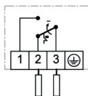
DWR XXX-513
DWR XXX-574-577
Ex-DWR XXX
1 Basic Equipment of the pressure monitors DWR.../DGM...
Chapter 1 describes the basic equipment and the installation of the pressure monitors DWR/DGM XXX (without any additional functions). Chapters 2-7 describe versions and additional functions.
1.1 Technical data (basic equipment)
Basic calibration:
Depending on series and intended purpose, FEMA pressure switches are either calibrated for falling or rising pressure. The table shows the calibration of the various devices and their versions.
| Basic device | Versions | |
| Calibrated under rising pressure | DWR | DWR...-203, -205, -213, -301, -303, -305, -313, -351, -353, -363, -513, -563, -576, -577 |
| Ex-DWR... | ||
| DGM..., | DGM...-205, -213, -301, -305, -313, -351, -363, -513, -563, -576, -577 | |
| EX-DGM... | ||
| Calibrated under falling pressure | n/a | DWR...206, -306, -574, -575 |
| n/a | DGM...206, -306, -574, -575 |
For devices calibrated under rising pressure the following applies:
If the maximum value of the setting range is set as the switching point, the reset point is lower by the value of the average switching differential. (e.g. DWR6: setting range 0.5-6 bar, switching point 6 bar, reset point 5.8 bar) If the minimum value of the setting range is used, then the lowest setting value is also the reset point. The switching point must be set higher by the value of the average switching differential (e.g. DWR6: 0.5-6 bar, switching point 0.7 bar, reset point 0.5 bar).
For devices calibrated for falling pressure the following applies:
If the minimum value of the setting range is used, then the lowest setting value is also the switching point. The reset point must be set higher by the value of the average switching differential (e.g. DWR6-206: 0.5-6 bar, switching point 0.5 bar, reset point 0.8 bar). If the maximum value of the setting range is used, then the highest value of the setting range is also the reset point. The reset point must be set higher by the value of the average switching differential (e.g. DWR6-206: setting range 0.5-6 bar, reset point 6 bar, switching point 5.7 bar).
The following applies for all devices:
All switching and reset points must be within the limits of the specified setting range given in the technical data sheet.
Switch
Single-pole changeover
Switching capacity
8 (5) A, 250 V AC
Installation position
Vertical to the top and horizontal
Max. ambient temperature
-25 to 70^ (DWR...)
-25 to 60^ (DGM...)
Max. medium temperature
70^ , (60^ on DGM) higher medium temperatures are possible if the above limiting values at the switching device are not exceeded by suitable measures (e.g. water pocket tube). At ambient temperatures below 0^ , ensure that no water condensation can arise in the sensor and in the switching device.
Switching difference
For values see data sheet
Pressure connection
External thread G^1 / 2A (pressure gauge connection) according to DIN 16288 and internal thread G^1 / 4 according to ISO 228, Part 1. (For gas applications internal thread permissible only up to 4 bar. Use flat gasket ring for pressure >4 bar.)
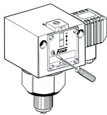
Switching device
Sturdy housing made of sea-water resistant aluminium die casting with plug connection (200) or terminal connection (500).
Degree of protection acc. to EN 60529
IP 54 (housing 200)
IP 65 (housing 500)
Materials
See data-sheet
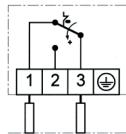
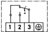
1.2 Electrical wiring
Connection layout
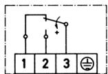
With rising pressure: 3-1 opens, 3-2 closes With falling pressure: 3-2 opens, 3-1 closes
Wiring
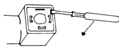
Wiring is on the angled plug. The cable outlet can be in any of 4 positions, which are at 90^ in relation to each other.
- Remove screw.
- Insert the screwdriver in the slot and press downwards.
On devices with terminal connection housing the terminal board is available after removing the terminal box lid.
Caution: Switch of voltage.
1.3 Pressure connection
Installation: Directly on the pipeline (pressure gauge connection G^1 / 2 ) or with 2 screws (4mm) on a level surface. Tighten only on the hexagonal of the pressure organ, never use the housing or plug as lever arm.
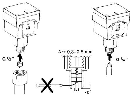
External thread G^_2^ (Pressure gauge connection) When using flat seals, turn in the centering screw (depth A approx. 0.3 - 0.5mm
Internal thread G^ / 4 In gas applications internal thread only up to 4 bar permissible. Use flat gasket ring for pressure >4 bar.
1.4 Setting the switching pressure
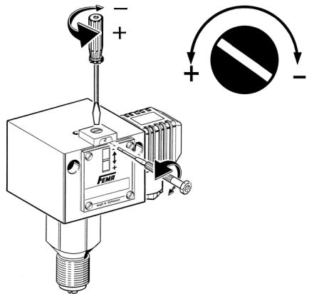
The switching pressure is set using the setting spindle. Before setting loosen the setscrew located above the scale by approx. 2 turns and tighten it again after setting.
The scale value corresponds to the upper switching point (for rising pressure). The lower switching point (for falling pressure) is lower by the switching difference. The scale serves as estimated value scale, a pressure gauge is required for accurate settings.
On terminal connection housings the setting screw is available after removing the cover.
Caution: Switch off voltage.
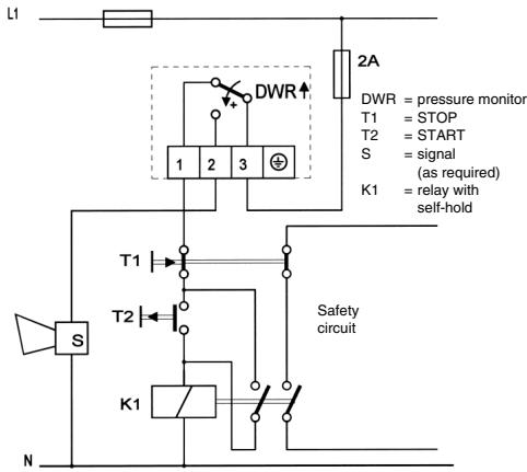
1.5 External electrical interlock in the switchgear cabinet (circuit proposal)
A pressure monitor can also be used as limiter if an electrical interlock is connected in series.
In pressure limitation in steam and hot water boilers, the external interlock is permissible only if it is assured that the pressure monitor is of "special design".
1.5.1 Maximum pressure limitation with external interlock
1.5.2 Minimum pressure limitation with external interlock
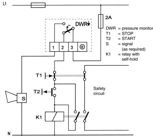
When the interlock circuit shown above is used, the requirements according to DIN 57116/VDE 0116 are fulfilled if the electrical plant, such as contactors or relays, correspond to the external interlock circuit VDE 0660 or VDE 0435 respectively.
2. Pressure monitors with adjustable switching difference DWR...-203 (not for DGM...)
2.1 Technical data as for 1.1
2.2 Electrical connection as for 1.2
2.3 Pressure connection as for 1.3
2.4 Setting
One spindle each is available for setting the switching pressure and the switching difference. Both spindles are arranged concentrically. The outer spindle with larger diameter influences the lower switching point, the switching difference and thus the upper switching point, is changed with the small grab screw located internally.
The action direction is indicated by the arrow direction.
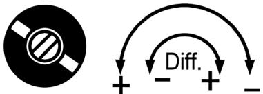
Setting sequence
a) Lower switching (with decreasing pressure), with outer spindle, according to scale or pressure gauge.
b) Switching difference (with increasing pressure), with small, internal group screw, results in upper switching point.
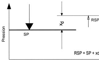
When the switching difference is changed, the lower switch-off point remains unchanged, the upper switching point is shifted by the switching difference.
$$ R S P = S P + x d $$
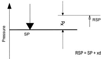
SP = switching point RSP = switch back point xd = switching difference (hysteresis)
3. Pressure limiters with mechanical interlock of the switching state (applies for DWR and roughly for DGM)
Maximum pressure limiter DWR...-205 ID: 0000020756
Minimum pressure limiter DWR...-206 ID: 0000020757
Instead of the microswitch with automatic reset, a "bistable" microswitch is installed in the limiters.
When the pressure reaches the value set on the scale, the microswitch switches over and remains in this position. The catch can be released by pressing in the unlocking button (marked on the scale side of the switching device by a red dot). The limiter can not be unlocked until the pressure has decreased by a certain amount or, in the case of interlocking at the lower switching point, is increased again. According to version, the interlock can be effective for a rising value DWR...-205 or for a falling value DWR...-206.
3.1 Technical data as for 1.1
3.2 Electrical connection
3.2.1 Maximum pressure limiter
Switching over and interlocking on rising temperature.
Additional function (...205). Connection of control circuit to terminal 1 and 3.
3.2.2 Minimum pressure limiter
Switching over and interlocking on falling temperature.
Additional function (...206). Connection of control circuit to terminal 2 and 3.
3.3 Pressure connection as for 1.3
DWR...-205
DWR...-206
3.4 Setting as for 1.4
Please note:
For maximum pressure limiters (205) the scale value corresponds to the upper switching point, for minimum pressure limiters (206) to the lower switching point.
4. Pressure limiters with gold plated contact
DWR...-213, DGM...-213
Gold plated contacts are used exclusively in the low voltage range in order to keep the transit resistance at the contacts low.
4.1 Technical data as for 1.1
Switching capacity:
max. 24 V DC
max. 100mA
min. 5 V DC
min. 4mA
At higher voltages and currents, the gold layer on the contacts will be damaged.
All other data correspond to the basic equipment.
5. Pressure monitors in intrinsically safe control circuits (EEx-i) DWR/DGM...-513
To be used only together with a suitable isolating amplifier, (e.g. Ex 011).
The attached connection diagram to the isolating amplifier has to be noted.
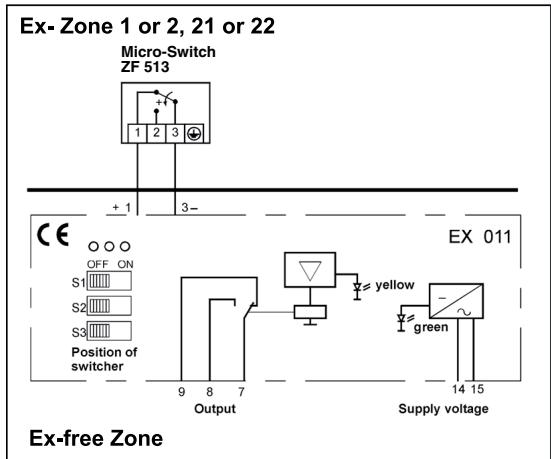
Connection diagram
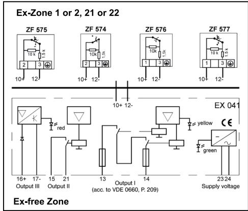
6. Pressure limiters/Pressure monitors in intrinsically safe control circuits with open-circuit and short-circuit monitoring (EEx-i)
The pressure monitors correspond in all technical data to the Type DWR (DGM). In addition, a resistance combination is provided in the switching device, which, together with the isolating amplifier EX 041, monitors the electric cables between isolating amplifier and pressure monitor for open circuit or short circuit. In the case of open circuit or short circuit, the system switches off towards the safe side. When choosing the type and when connecting please strictly distinguish between maximum pressure and minimum pressure monitoring, as well as monitoring and limitation function.
7. Pressure monitors in EEx-d version Ex-DWR..., Ex-DGM...
Ex-pressure monitors must be supplied in the form that has been tested according to ATEX.
Versions and additional functions are basically not possible.
7.1 Technical data of the Ex switching device
Type of Ex-protection
EX II 2 G D EEx de IIC T6 IP65 T80°C
Ex approval
PTB 02 ATEX 1121
Ex-Zone
Compatible for zones 1 and 2, 21 and 22
Form of protection
IP 65 (vertical position)
Ambient temperature
-15 to +60 °C
Max. temperature at pressure switch 60^
Max. medium temperature for pressure switches
60^ C
Higher medium temperatures are possible if the appropriate measures (e.g. water sack pipe) are taken so that the above mentioned ranges are not exceeded on the switch.
Cable entry
M 16 x 1,5
For fixed installation only
Switching difference
Not adjustable, approximate values seed data sheet
Fitting position
Vertically upwards
7.2 Electrical data
Connection plan
The terminal board can be accessed after the protective casing has been removed. After connecting the supply lines, the protective casing should in all cases be reattached.
With increasing pressure 3-1 will be interrupted and 3-2 will be closed.
Switching element
Single-poled, changeover microswitch.
Protection of the conductive connection
Can be accessed after removing the terminal board casing.
Earthing connection/potential connection
The maximal cross section of the cable is 4mm^2
Switching power
3 A 250 V AC, 2 A 250 V AC (inductive)
0.03 A 250 V DC, 3 A 24 V DC
7.3 Pressure connection as for 1.3
7.4 Setting of switching point
The switching point can be set within the range given in the datasheet by using a screwdriver on the setting spindle. Additionally you should remove the terminal board casing (with 4 hexagon screw M 4). The affixing screw on the front end (above the scale) has to be removed and should be reattached after setting the switching point.
Turning the setting spindle clockwise gives a lower switching point, turning anticlockwise gives a higher switching point.
The scale should be used as a guide, for more exact settings you should use a manometer.
7.5 Serial numbers
All switch units and their respective terminal board casings are marked with a serial number. When installing you should ensure that the terminal board casings do not get mixed up.
Important notice:
When installing the Ex switch units and setting them up for operation you should comply with the recognised rules and guidelines for installations in Ex-areas.
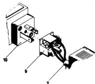
Ex-cable gland (4) only to be used for fixed installation.
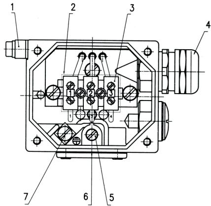
1 Potential equalisation
2 Protective casing for terminals (removable)
3 Connection terminals
4 Cable inlet M 16 x 1,5
5 Switching point adjustment
6 Locking bolt for setting spindle
7 Protection of the conductive connection
Utilisation
Vapeur
Eau chaude
Gaz combustibles
Combustibles liquids
Attention: Couper la tension.
$$ R S P = S P + x d $$
Manufactured for and on behalf of the Environmental and Combustion Controls Division of Honeywell Technologies Sàrl, Ecublens, Route du Bois 37, Switzerland by its Authorized Representative:
FEMA Regelerge
Honeywell GmbH
Böblinger Straße 17
71101 Schonaiich
Deutschland
Telefon 0 70 31 / 6 37-02
Telefax 0 70 31 / 6 37-8 50
FEMA Controls
Honeywell GmbH
Böblinger Straße 17
71101 Schonaich
Germany
Phone 0 70 31 / 6 37-02
Fax 07031/637-850
7157.134/20
MU2B-0264GE51 R0708