
BA195 MINIBA - Water backflow preventer HONEYWELL - Free user manual and instructions
Find the device manual for free BA195 MINIBA HONEYWELL in PDF.

| Product type | Backflow preventer (disconnector) |
| Brand | Honeywell |
| Model | BA195 MINIBA |
| Fluid | Water |
| Maximum inlet pressure | 10.0 bar |
| Minimum inlet pressure | 1.5 bar |
| Maximum service temperature | 65 °C |
| Mounting position | Horizontal, outlet connection downwards |
| Outlet connection | DN 50 (plastic pipe HT 50) |
| Nominal width | 3/8" |
| Standard version | BA195-3/8E with threaded connection 3/4" |
| Main function | Protection of drinking water network against backflow and back-siphonage |
| Pressure zones | 3 zones, drain valve opens at ΔP ≤ 0.14 bar |
| Integrated strainer | Yes, mesh size 0.5 mm |
| Cartridge | Integrated check valve and drain valve, replaceable |
| Outlet-side check valve | Yes, replaceable (destroyed upon disassembly) |
| Body material | Dezincification-resistant brass |
| Cartridge material | High-quality synthetic material |
| Sealing | Elastomers approved for drinking water |
| Recommended inspection | Every 6 months |
| Recommended maintenance | Every 1 to 3 years |
| Compatible accessories | Test kit TK295 or TKA295, maintenance kit WS195 |
| Spare parts | Complete cartridge KE195, check valve 2110200, outlet connection AT295 |
| Freeze protection | Installation location protected from frost and well ventilated |
Frequently Asked Questions - BA195 MINIBA HONEYWELL
User questions about BA195 MINIBA HONEYWELL
0 question about this device. Answer the ones you know or ask your own.
Ask a new question about this device
Download the instructions for your Water backflow preventer in PDF format for free! Find your manual BA195 MINIBA - HONEYWELL and take your electronic device back in hand. On this page are published all the documents necessary for the use of your device. BA195 MINIBA by HONEYWELL.
USER MANUAL BA195 MINIBA HONEYWELL
natural_image
Technical line drawing of a pipe fitting with multiple ports and fittings (no text or symbols)Keep instructions for later use!
- Follow the installation instructions.
- Use the appliance
• according to its intended use
- in good condition
• with due regard to safety and risk of danger.
3. Note that the appliance is exclusively for use in the applications detailed in these installation instructions. Any other use will not be considered to comply with requirements and would invalidate the warranty.
4. Please take note that any assembly, commissioning, servicing and adjustment work may only be carried out by authorized persons.
5. Immediately rectify any malfunctions which may influence safety.
2. Functional description
BA type backflow preventers are divided into three pressure zones. The pressure in zone ① is higher than in zone ②, which in turn is higher than in zone ③. A discharge valve is connected to zone ② which opens at the latest when the differential pressure between zones ① and ② falls to 0.14 bar. The water from zone ② discharges to atmosphere. In this way the danger of back pressure or back syphonage into the supply network is prevented. The pipework connection is interrupted and the drinking water network is protected.
3. Application
| Medium | Water |
| Maximum inlet pressure | 10.0 bar |
| Minimum inlet pressure | 1.5 bar |
4. Technical data
Installation position Horizontal with discharge valve downwards
Max. operating temperature 65°C
Discharge pipe connection DN 50
Nominal diameter 3/8"
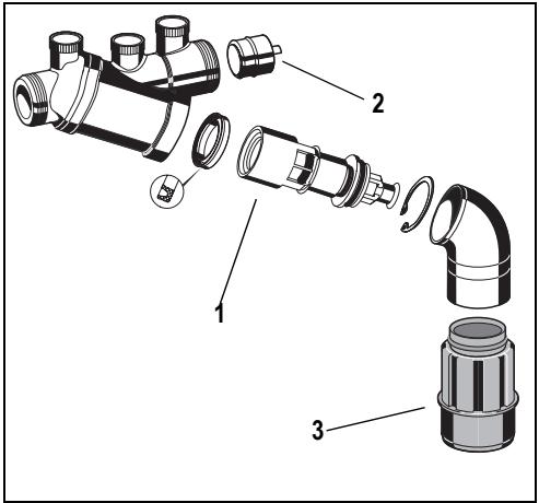
5. Scope of delivery
The backflow preventer consists of:
- Housing
- Integral strainer, mesh size approx. 0.5 mm
- Valve cartridge with integral check valve and discharge valve
- Outlet check valve
- Discharge connection
6. Options
BA195-3/8E = Standard version with connection thread 3/4"
7. Assembly
7.1 Installations Guidelines
• Install shutoff valves before and after backflow preventer
- Install in horizontal pipework with the discharge valve downwards
- Ensure good access
o Simplifies maintenance and inspection
- Backflow preventers of this type have an integral strainer which protects the device from the ingress of dirt. With highly polluted water a fine filter should be installed upstream to ensure the correct function of the device.
- Do not install in places where flooding can occur
- The installation environment should be protected against frost and ventilated well
- Install discharge pipework which has adequate capacity
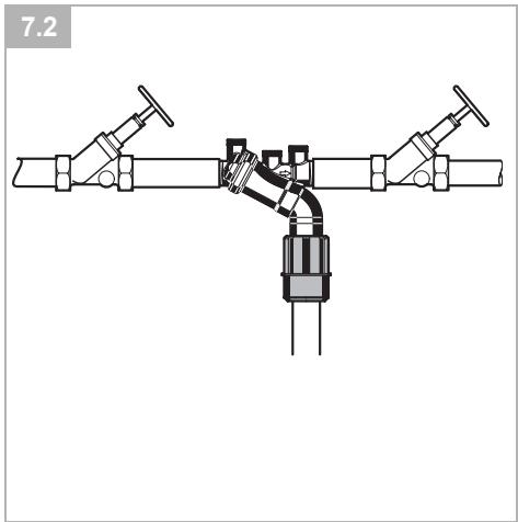
7.2 Assembly instructions
- Thoroughly flush pipework
- Install backflow preventer
- Install in horizontal pipework with discharge connection directed downwards
- Note flow direction (indicated by arrow) o Install without tension or bending stresses
- Provide a straight section of pipework of at least five times the nominal valve size after the backflow preventer
- Attach drain pipe to discharge connection (plastic pipe HT 50)
- The appliance is ready for use
8. Maintenance
We recommend a planned maintenance contract with an installation company
Maintenance of backflow preventer must be carried out by authorized personnel!
Disassemble ball valves after maintenance!
8.1 Inspection

• Frequency: every 6 month (depending on local operating conditions)
• To be carried out by an installation company
- Inspection with a test control unit and maintenance-set (see accessories)
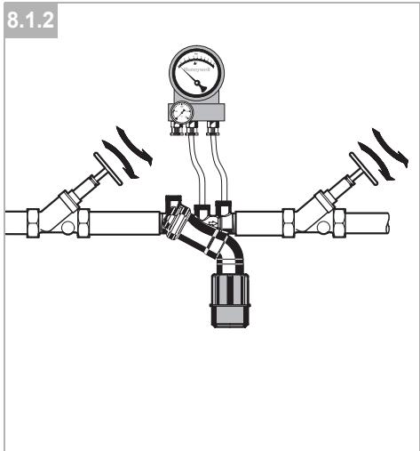
8.1.1 Testing discharge valve

Take note of the instructions of the test control unit TKA295 or TK295
- Procedure according to instruction of the test control unit TKA295 resp. TK295

Quick test for the discharge valve:
- Lower the inlet pressure o if the discharge valve opens (it drops), the function is o.k.
8.1.2 Testing outlet check valve

Take note of the instructions of the test control unit TKA295 or TK295
- Procedure according to instruction of the test control unit TKA295 resp. TK295
8.2 Maintenance

We recommend a planned maintenance contract with an installation company
In accordance with DIN EN 1717 a regular maintenance must be taken.

Frequency: every 1-3 years (depending on local operating conditions) To be carried out by an installation company
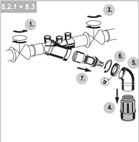
8.2.1 Cartridge insert
- Close shutoff valve on inlet
- Release pressure on outlet side (e.g. through water tap)
- Close shut off valve on outlet
- Unscrew discharge connection
- Remove elbow pipe
- Remove retaining ring
- Replace cartridge insert and lip seal

- Don't disassemble cartridge insert to individual parts!
- Reassemble in reverse order o push down the cartridge insert till it snaps in
- Test function (see chapter inspection)
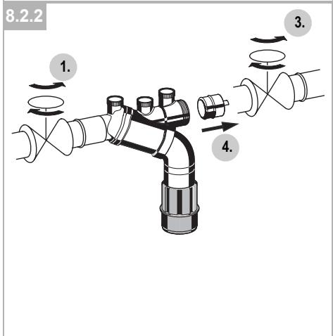
8.2.2 Check valve
- Close shutoff valve on inlet
-
Release pressure on outlet side (e.g. through water tap)
-
Close shut off valve on outlet
-
Exchange check valve

Check valve will be destroyed after demounting
- Test function (see chapter inspection)
8.3 Cleaning

• To be carried out by an installation company
• To be carried out by the operator
If necessary, the cartridge insert can be cleaned.

Do not use any cleaning agents containing solvents and/or alcohol to clean the plastic parts!

Detergents must not be allowed to enter the environment or the sewerage system!
- Close shutoff valve on inlet
- Release pressure on outlet side (e.g. through water tap)
- Close shut off valve on outlet
- Unscrew discharge connection
- Remove elbow pipe
- Remove retaining ring
- Clean or replace cartridge insert and lip seal

- Don't disassemble cartridge insert to individual parts!
- Reassemble in reverse order o push down the cartridge insert till it snaps in
- Test function (see chapter inspection)
9. Disposal
- Dezincification resistant brass housing
• High-quality synthetic material valve cartridge - High-quality synthetic material or red bronze check valves
- Sealing elements made of elastomer materials suitable for drinking water
- High-quality synthetic material discharge connection

Observe the local requirements regarding correct waste recycling/disposal!
- Troubleshooting
| Problem | Cause | Remedy |
| Discharge valve opens without apparent reason | Pressure strokes in water supply system | Install a pressure reducing valve upstream the backflow preventer |
| Fluctuating inlet pressure | Install a pressure reducing valve upstream the backflow preventer | |
| Cartridge insert is contaminated | Remove cartridge insert and exchange it | |
| Discharge valve don’t close | Deposits on valve seat | Remove cartridge insert and clean or exchange it |
| Damaged ’o’ring | Remove cartridge insert and exchange it | |
| Leaky discharge valve | Remove cartridge insert and clean or exchange it | |
| Flow is to low | Inlet strainer is blocked | Remove strainer and clean it |
- Spare Parts
Cartridge insert 3/8" KE195 complete
Check valve insert 3/8" 2110200
complete
Discharge connection AT295
- Accessories
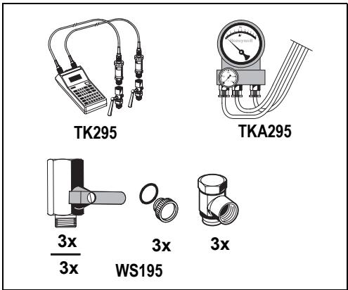
Electronic pressure measuring device with digital indicator, battery-operated.
With case and accessories, ideal for inspection and maintenance of backflow preventer type BA.
TKA295 Test kit
Analogue pressure measuring device with differential pressure display.
With case and accessories, ideal for inspection and maintenance of backflow preventer type BA.
WS195 Maintenance-set
Maintenance-set for BA195 type backflow preventers for use with Test kit TK295 resp. TKA295
Automation and Control Solutions
Honeywell GmbH
Hardhofweg
D-74821 Mosbach
Phone: (49) 6261 810
Fax: (49) 6261 81309
http://europe.hbc.honeywell.com
www.honeywell.com
Manufactured for and on behalf of the
Environmental and Combustion Controls Division of
16, Switzerland by its Authorised Representative Ho-
neywell GmbH
EN0H-1233GE23 R1108
Subject to change
natural_image
Pure mechanical diagram of a pipe connection with two arms and a central valve (no text or symbols)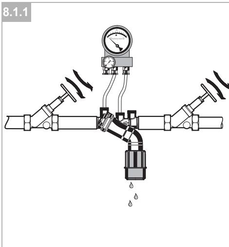
- Sicherheitshinweise ...... 2
- Funktionsbeschreibung ..... 2
- Verwendung 2
- Technische Daten ...... 2
- Lieferumfang 2
- Varianten 2
- Montage 2
- Instandhaltung 2
- Entsorgung 3
- Störungen / Fehlersuche ....4
- Ersatzteile 4
-
Zubehör 4
-
Avvertenze di sicurezza ...... 11
- Descrizione del funzionamento ..... 11
- Uso 11
- Dati tecnici 11
- Fornitura 11
- Varianti 11
- Montaggio.... 11
- Manutenzione ..... 11
- Smaltimento 12
- Guasti / Ricerca guasti ...... 13
- Pezzi di ricambio 13
-
Accessori 13
-
Safety Guidelines .... 5
- Functional description .... 5
- Application 5
- Technical data .... 5
- Scope of delivery 5
- Options 5
- Assembly 5
- Maintenance 5
- Disposal 6
- Troubleshooting 7
- Spare Parts ....7
-
Accessories ...... 7
-
Wskazówki bezpieczeństwa ..... 14
- Opis funkcji 14
- Zastosowanie 14
- Dane techniczne 14
- Zakres dostawy 14
- Warianty 14
- Montaż 14
- Utrzymywanie w dobrym stanie .... 14
- Usuwanie 15
- Zakłócenia / poszukiwanie usterek 16
- Części zamienne .... 16
-
Wyposażenie dodatkowe ..... 16
-
Consignes de sécurité ....8
- Description fonctionnelle .... 8
- Mise en oeuvre 8
- Caractéristiques 8
- Contenu de la livraison.... 8
- Variantes 8
- Montage 8
- Maintenance 8
- Matériel en fin de vie ...... 9
- Défaut / recherche de panne ..... 10
- Pièces de rechange .... 10
- Accessoires .... 10
- Functional description
- Application
- Technical data
- Scope of delivery
- Options
- Assembly
- Installations Guidelines
- Assembly instructions
- Maintenance
- Inspection
- Testing discharge valve
- Testing outlet check valve
- Maintenance
- Cartridge insert
- Check valve
- Cleaning
- Disposal
- TKA295 Test kit
- WS195 Maintenance-set
- Automation and Control Solutions
Brand : HONEYWELL
Model : BA195 MINIBA
Category : Water backflow preventer