405028X51 - Riding lawn mower MURRAY - Free user manual and instructions
Find the device manual for free 405028X51 MURRAY in PDF.
User questions about 405028X51 MURRAY
0 question about this device. Answer the ones you know or ask your own.
Ask a new question about this device
Download the instructions for your Riding lawn mower in PDF format for free! Find your manual 405028X51 - MURRAY and take your electronic device back in hand. On this page are published all the documents necessary for the use of your device. 405028X51 by MURRAY.
USER MANUAL 405028X51 MURRAY
Model No. 405021x51A
Product Type
Mfg. No.
Description
7800279
40" Murray CE Riding Mower

CAUTION: Read and
follow all instructions.
Manual Part No. 7101969
Revision 00
Rev. Date 01/2008
TP 199-4811-00-RD-R
International Pictorials 4
Limited Warranty 5
Owner's Information. 6
Safe Operation Practices 7
Assembly 9
Operation 11
Maintenance Chart 15
Maintenance 16
Troubleshooting Chart. 25

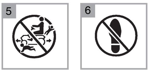


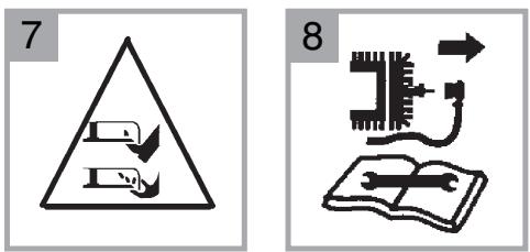
IMPORTANT: The following pictorial are located on your unit or on literature supplied with the product. Before you operate the unit, learn and understand the purpose for each pictorial.
Safety Warning Pictorials
1WARNING
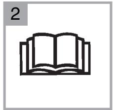
2 IMPORTANT: Read Owner's Manual Before Operating This Machine.
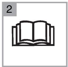
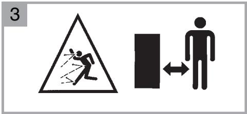
3 WARNING: Thrown Objects. Keep Bystanders Away. Read User Instructions Before Operating This Machine.
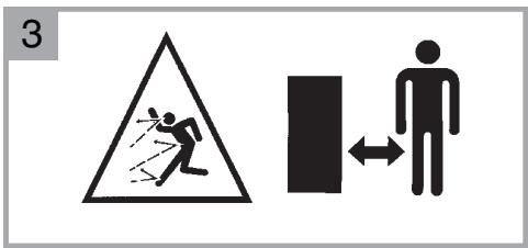
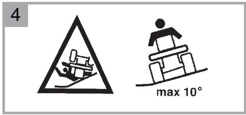
4 WARNING: Do Not Use This Machine On Slopes Greater Than 10 Degrees.
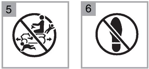
5 DANGER: Keep People, Especially Children, Away From Unit.
6 DANGER: No Step.
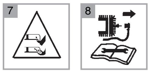
7 DANGER: Keep Feet And Hands Away From Rotating Blade.
8 DANGER: Disconnect Spark Plug Wire Before Servicing Unit.
9WARNING: Hot Surface.
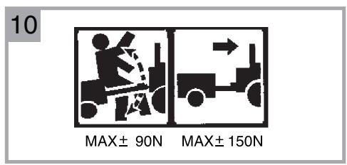
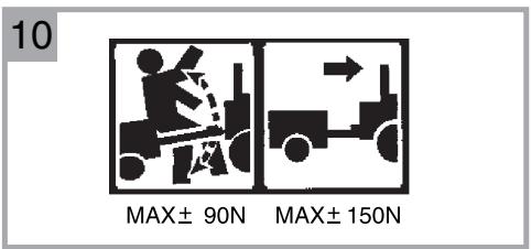
10 WARNING: Use Caution When Connecting Or Disconnecting Accessories.
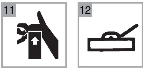
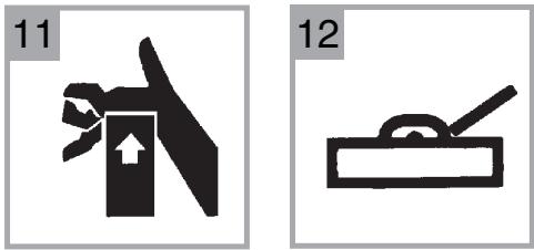
11 WARNING: Crushed Fingers.
12 IMPORTANT: Follow Instructions In Owner's Manual To Level The Deck.
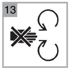
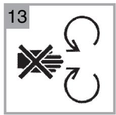
13 WARNING: Stay Clear Of Mower Blade As Long As Engine Is Running.
Control and Operating Pictorialis
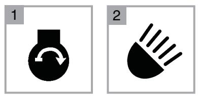
1 Engine Start
2 Lights
3 Engine Stop
4 Engine Run
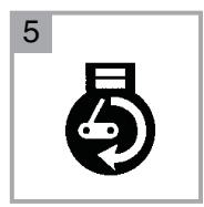
5 Engine Run
6 Brake
7 Parking Brake
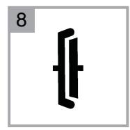
8 Clutch
9 Slow
10 Fast
11 Choke
12 Oil
13 Blade Rotation Control
14 Raise
15 Fuel
BRIGGS & STRATTON CORPORATION OWNER WARRANTY POLICY
Effective January 1, 2006 replaces all undated Warranties and all Warranties dated before January 1, 2006
LIMITED WARRANTY
Briggs & Stratton Corporation will repair or replace, free of charge, any part(s) of the product that is defective in material or workmanship or both. Transportation charges on product submitted for repair or replacement under this warranty must be borne by purchaser. This warranty is effective for the time periods and subject to the conditions stated below. For warranty service, find the nearest Authorized Service Dealer in your area. For warranty service, find the nearest Authorized Service Dealer in our dealer locator map at www.murray.com.
THERE IS NO OTHER EXPRESS WARRANTY. IMPLIED WARRANTYES, INCLUDING THOSE OF MERCHANTABILITY AND FITNESS FOR A PARTICULAR PURPOSE, ARE LIMITED TO ONE YEAR FROM PURCHASE, OR TO THE EXTENT PERMITTED BY LAW ANY AND ALL IMPLIED WARRANTYES ARE EXCLUDING. LIABILITY FOR INCIDENTAL OR CONSEQUENTIAL DAMAGES ARE EXCLOSED TO THE EXTENT EXCLUSION IS PERMITTED BY LAW. Some states or countries do not allow limitations on how long an implied warranty lasts, and some states or countries do not allow the exclusion or limitation of incidental or consequential damages, so the above limitation and exclusion may not apply to you. This warranty gives you specific legal rights and you may also have other rights which vary from state to state or country to country.
WARRANTY TERMS
Brand / Unit
Consumer
Use
Commercial
Use
Condition of
Warranty Term
Riders / Tractors 2 years 90 days
The warranty period begins on the date of purchase by the first retail consumer or commercial end user, and continues for the period of time stated in the table above. "Consumer use" means personal residential household use by a retail consumer. "Commercial use" means all other uses, including use for commercial, income producing or rental purposes. Once product has experienced commercial use, it shall thereafter be considered as commercial use for purposes of this warranty.
No warranty registration is necessary to obtain warranty on Murray branded products. Save your proof of purchase receipt. If you do not provide proof of the initial purchase date at the time warranty service is requested, the manufacturing date of the product will be used to determine the warranty.
ABOUT YOUR WARRANTY
We welcome warranty repair and apologize to you for being inconvenienceed. Any Authorized Service Dealer may perform warranty repairs. Most warranty repairs are handled routinely, but sometimes requests for warranty service may not be appropriate. For example, warranty service would not apply to the product if damage occurred because of misuse, lack of routine maintenance, shipping, handling, warehousing or improper installation. Similarly, the warranty is void if the serial number on the product has been removed or the product has been altered or modified.
This warranty covers product related defective material and/or workmanship only. To avoid misunderstanding which might occur between the customer and the Dealer, listed below are some of the causes of product failure that the warranty does not cover.
- Normal Wear: Small Engine Powered Equipment, like all mechanical devices, needs periodic parts and service to perform well. Warranty does not cover repair when normal use has exhausted the life of the product or part.
- Installation: This warranty does not apply to product that has been subjected to improper or unauthorized installation, alteration or modification. Nor installations that prevent starting, cause unsatisfactory engine performance.
- Improper Maintenance: The life of this product depends upon the conditions under which it operates, and the care it receives. Recommended maintenance and adjustment intervals are stated in the Operator's Manual. Often product, such as tillers, edgers, rotary mowers, are used in dusty or dirty conditions, which can cause what appears to be premature wear. Such wear, when caused by dirt, dust, or other abrasive material entering the product because of improper maintenance is not covered by warranty. The warranty will not cover repairs due to problems caused by replacement parts that are not original manufactured part(s).
Incorrect and/or insufficient fuel or lubrication: This warranty does not cover damage caused by the use of stale fuel, or altered gasolines. Damage to engine or engine components ie, combustion chamber, valves, valve seats, valve guides, burned starter motor windings caused by use of alternate fuels such as liquified petroleum, natural gas, are not covered unless engine is certified for this operation. Parts which are scored or broken because product was operated with insufficient, contaminated or incorrect grade of lubricating oil as well as product components damaged due to lack of lubrication are not covered. - Operational Misuse: Proper operation of the product is stated in the Operator's Manual. Product damaged by overspeeding, overheating, or operation in a confined area without sufficient ventilation. Product broken by excessive vibration caused by a loose engine mounting, loose or unbalanced blades, impellers, overspeeding, or bent crankshaft due to striking of solid object. Damage or malfunctions resulting from accidents, abuse, or improper servicing or freezing or chemical deterioration, as well as operating in excess of recommended capacities as outlined in the Operator's Manual are not covered.
Routine tune-up, wear items or adjustments: This warranty excludes wear items such as oil, belts, blades, o-rings, filters, etc.
Other exclusions: Repair or adjustments for part(s) that are not manufactured by Briggs & Stratton Corporation, are not covered, see warranty for respective manufacturers. This warranty excludes failures due to acts of God and other major forceful events beyond the manufacturers control. Also excluded are used, reconditioned, and demonstration products.
Warranty service is available only through Authorized Service Dealers. Locate your nearest dealer in our locator map at www.murray.com.
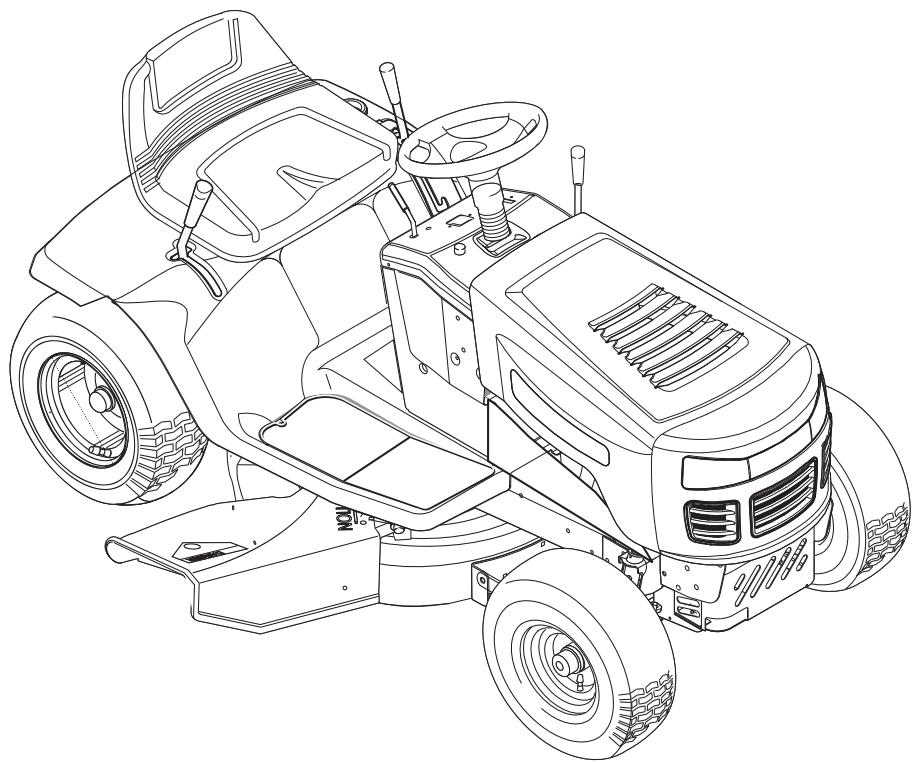
Know Your Product
If you understand the unit and how the unit operates, you will get the best performance. As you read this manual, compare the illustrations to the unit. Learn the location and the function of the controls. To help prevent an accident, follow the operating instructions and the safety rules. Keep this manual for future reference.

WARNING
Look for this symbol to indicate important safety precautions. This symbol indicates: "Attention! Become Alert! Your Safety Is At Risk."
Responsibility of the Owner

WARNING
This cutting machine is capable of amputating hands and feet and throwing objects. Failure to observe the following safety instructions could result in serious injury or death to the operator or bystanders.
The responsibility of the owner is to follow the instructions below.
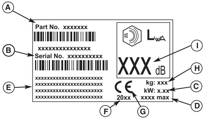
CE Identification Tag Markings
A. Manufacturer's Identification Number
B. Manufacturer's Serial Number
C. Power Rating in Kilowatts
D. Maximum Engine Speed in Rotations per Minute
E. Manufacturer's Name and Address
F. Year of Manufacture
G. CE Compliance Logo
H. Mass of Unit in Kilograms
I. Guaranteed Sound Power in Decibels
For Ride-On (Riding) Rotary Mower Machines
Training
- Read the instructions carefully. Be familiar with the controls and the proper use of the equipment.
- Never allow children or people unfamiliar with these instructions to use the mower. Local regulations may restrict the age of the operator.
- Never mow while people, especially children, or pets are nearby.
- Keep in mind that the operator or user is responsible for accidents or hazards occurring to other people or their property.
- Do not carry passengers.
- All drivers should seek and obtain professional and practical instruction. Such instruction should emphasize:
a. the need for care and concentration when working with ride-on machines;
b. control of a ride-on machine sliding on a slope will not be regained by the application of the brake. The main reasons for loss of control are:
insufficient wheel grip;
- being driven too fast;
- inadequate braking;
- the type of machine is unsuitable for its task;
- lack of awareness of the effect of ground conditions, especially slopes;
- incorrect hitching and load distribution.
Preparation
- While mowing, always wear substantial footwear and long trousers. Do not operate the equipment when barefoot or wearing open sandals.
-
Thoroughly inspect the area where the equipment will be used and remove all objects which may be thrown by the machine.
-
WARNING-Petrol is highly flammable.
a. Store fuel in containers specifically designed for this purpose.
b. Refuel outdoors only and do not smoke while refuelling.
c. Add fuel before starting the engine. Never remove the cap of the fuel tank or add petrol while the engine is running or when the engine is hot.
d. If petrol is spilled, do not attempt to start the engine but move the machine away from the area of spillage and avoid creating any source of ignition until petrol vapors have dissipated.
e. Replace all fuel tanks and container caps securely.
- Replace faulty silencers.
- Before using, always visually inspect to see that the blades, blade bolts and cutter assembly are not worn or damaged. Replace worn or damaged blades and bolts in sets to preserve balance.
- On multi-blade machines, take care as rotating one blade can cause other blades to rotate.
Operation
- Do not operate the engine in a confined space where dangerous carbon monoxide fumes can collect.
- Mow only in daylight or in good artificial light.
- Before attempting to start the engine, disengage all blade attachment clutches and shift into neutral.
- Do not use slopes of more than 10 degrees.
- Remember there is no such thing as a "safe" slope. Travel on grass slopes requires particular care. To guard against overturning:
a. do not stop or start suddenly when going up or downhill;
b. engage clutch slowly, always keep machine in gear, especially when travelling downhill;
c. machine speeds should be kept low on slopes and during tight turns;
d. stay alert for humps and hollows and other hidden hazards;
e. never mow across the face of the slope, unless the mower is designed for this purpose.
- Use care when pulling loads or using heavy equipment.
a. Use only approved drawbar hitch points.
b. Limit loads to those you can safely control.
c. Do not turn sharply. Use care when reversing.
d. Use counterweight(s) or wheel weights when suggested in the Instruction Book.
- Watch out for traffic when crossing or near roadways.
-
Stop the blades rotating before crossing surfaces other than grass.
-
When using any attachments, never direct discharge of material toward bystanders nor allow anyone near the machine while in operation.
- Never operate the mower with defective guards or shields, or without safety protective devices in place.
- Do not change the engine governor settings or overspeed the engine. Operating an engine at excessive speed may increase the hazard of personal injury.
- Before leaving the operator's position
a. disengage the power take-off and lower the attachments;
b. change into neutral and set the parking brake;
c. stop the engine and remove the key.
- Disengage drive to attachments, stop the engine, and disconnect the spark plug wire(s) or remove the ignition key
a. before cleaning blockages or unclogging chute;
b. before checking, cleaning or working on the mower;
c. after striking a foreign object. Inspect the mower for damage and make repairs before restarting and operating the equipment;
d. if the machine starts to vibrate abnormally (check immediately).
- Disengage drive to attachments when transporting or not in use.
- Stop the engine and disengage drive to attachment
a. before refuelling;
b. before removing the grass catcher;
c. before making height adjustment unless adjustment can be made from the operator's position.
- Reduce the throttle setting during engine run-out and, if the engine is provided with a shut-off valve, turn the fuel off at the conclusion of mowing.
- Before and when backing, look behind and down for small children.
- Use extra care when approaching blind corners, shrubs, trees or other objects that may obscure vision.
Maintenance and Storage
- On multi-blade machines, take care as rotating one blade can cause other blades to rotate.
- When machine will be parked, stored or left unattended, lower the cutting means unless a positive mechanical lock is used.
- Keep all nuts, bolts, and screws tight to be sure the equipment is in safe working condition.
- Never store the equipment with petrol in the tank inside a building where fumes may reach an open flame or spark.
- Allow the engine to cool before storing in any enclosure.
- To reduce the fire hazard, keep the engine, silencer, battery compartment and petrol storage area free of grass, leaves, or excessive grease.
- Check the grass catcher frequently for wear or deterioration.
- Replace worn or damaged parts for safety.
- If the fuel tank has to be drained, this should be done outdoors.
All fasteners are in the parts bag. Do not discard any parts or material until the unit is assembled.

WARNING
Before doing any assembly or maintenance to the mower, remove the wire from the spark plug.
NOTE: In this instruction book, left and right describe the location of a part with the operator on the seat.
Install the Front Wheels
Use a knife and cut the four sides of the container. Install the front wheels (1) in the container (see Figure 1).
NOTE: Use a piece of wood about 4 feet (1.25 meters) long to raise the front of the tractor. If a piece of wood cannot be found, get another person to help lift the tractor. Be careful, do not let the tractor fall.
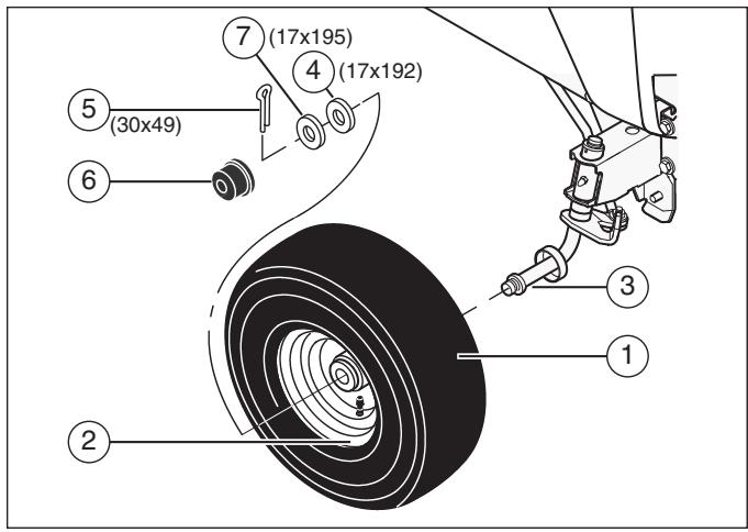
Figure 1
- Raise the front of the tractor. Set a support (block of wood) under the tractor.
- Make sure the valve stem (2) is to the outside of the tractor. Slide the front wheel (1) on the spindle (3).
- Fasten each front wheel with washer (4), washer (7) and cotter pin (5). Bend the ends of the cotter pin apart to keep the front wheel on the spindle.
- After the front wheels are installed, lift the tractor from the support. Roll the tractor off of the container.
- If your tractor has hub caps (6), install the hub caps. Make sure the washers hold the hub caps in place.
Install the Seat
- Carefully remove the plastic bag from the seat.
- Align the holes in the seat hinge (2) to the holes in the seat (1) (see Figure 2). Fasten the seat to the seat hinge with the fasteners (4) and (5).
- Check the operating position of the seat. If the seat needs to be adjusted, loosen the two wing bolts (5). Slide the seat forward or backward along the seat adjusting holes (3). Tighten the wing bolts.
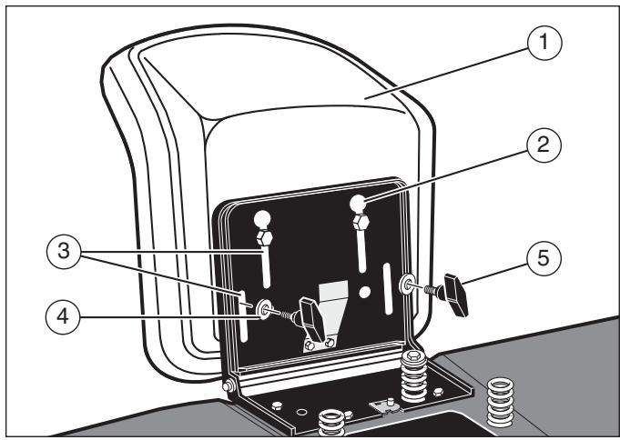
Figure 2
Assemble the Steering Wheel
- Make sure the front wheels point forward.
- Slide the cover (3) over the steering post (2) (see Figure 3). Make sure the collar of the cover is on top.
- Slide the steering wheel (1) onto the steering post.
- Attach the steering wheel to the steering post with screw (4) and washer (6).
- Some models have an optional insert (7) in the parts bag. Attach the insert to the center of the steering wheel.
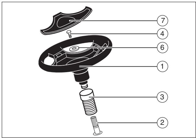
Figure 3
Maintenance Free Battery
IMPORTANT: Before you attach the battery cables to the battery, check the battery date. The battery date tells if the battery must be charged.
- Check the top of the battery (1) for the location of the battery date (see Figure 4).
- If the battery is put into service before the battery cables can be attached without charging the battery. See "Install the Battery Cables."
- If the battery is put into service after the battery must be charged. See "Charge the Battery."
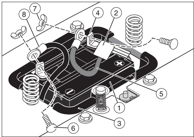
Figure 4
Charge the Battery

WARNING
When you charge the battery, do not smoke. Keep the battery away from any sparks. The fumes from the battery acid can cause an explosion.
- Remove the battery (1) and battery tray (3) (see Figure 4).
- Remove the protective caps from the battery terminals.
- Use a 12 volt battery charger to charge the battery. Charge at a rate of 6 amps for one hour. If you do not have a battery charger, have an authorized service center charge the battery.
- Install the battery (1) and battery tray (3). Make sure the positive (+) terminal (4) is on the left side.
Install the Battery Cables

WARNING
To prevent sparks, fasten the red cable to the positive (+) terminal before you connect the black cable.
- Remove the protective caps from the battery terminals (see Figure 4).
- Slide the terminal cover (2) on to the red cable (5). Fasten the red cable to the positive (+) terminal (4) with the fasteners (6) and (7).
- Fasten the black cable (8) to the negative (-) terminal with the fasteners (6) and (7).
Check the Tires
Check the air pressure in the tires. Tires with too much air pressure will cause the unit to ride rough. Also, the wrong air pressure will keep the mower housing from cutting level. The correct air pressure is: Front Tires 0,97 BAR (14 PSI), Rear Tires 0,69 BAR (10 PSI). The tires were over inflated for shipment.
Check the Level of the Mower Housing
Make sure the level of cut is still correct. After you mow a short distance, look at the area that was cut. If the mower housing does not cut level, see the instructions to "Level the Mower Housing" in the Maintenance section of this instruction book.
Prepare the Engine
NOTE: The engine was shipped from the factory filled with oil. Check the level of the oil. Add oil as needed.
See the engine manufacturer's instructions for the type of petrol and oil to use. Before you use the unit, read the information on safety, operation, maintenance, and storage.

WARNING
Follow the engine manufacturer's instructions for the type of petrol and oil to use. Always use a safety petrol container. Do not smoke when adding petrol to the engine. When inside an enclosure, do not fill with petrol. Before you add petrol, stop the engine. Let the engine cool for several minutes.
Important! Before You Start Mowing
Check the engine oil.
- Fill the fuel tank with petrol.
- Check the air pressure of the tires.
- Check the level of the mower housing.
- Attach the battery cables.
Location of Controls
Blade Rotation Control (1): Use the blade rotation control to start and stop the rotation of the blade (see Figure 5).
Clutch/Brake Pedal (2): The pedal has two functions. The first function is a clutch. The second function is a brake.
Headlight Switch (3): The headlight switch is the first part of the ignition switch. To use the lights with the engine running, turn the key to the position for the lights.
Ignition Switch (3): Use the ignition switch to start and stop the engine.
Shift Lever (4): Use the shift lever to change the speed of the unit.
Lift Lever (5): Use the lift lever to change the height of cut.
- Parking Brake Lever (6): Use the parking brake lever to engage the brake when you leave the unit.
Throttle Control Lever (7): Use the throttle control lever to increase or decrease the speed of the engine.
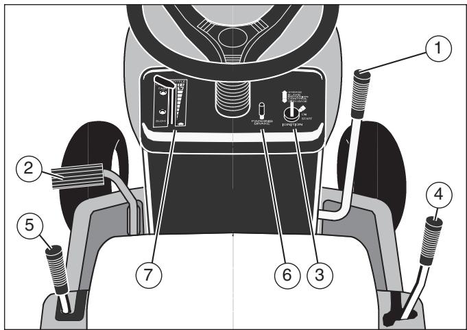
Figure 5
Attachments
This unit can use many different attachments. This unit can pull attachments like a lawn sweeper, a lawn aerator, or a hopper spreader. This unit cannot use attachments that engage the ground like a plough, a disk harrow, or a cultivator.
For trailer and pull-behind attachments, the maximum weight is 113kg (250 lbs).
Use the Throttle Control
Use the throttle control (7) to increase or decrease the speed of the engine (see Figure 5).
- The FAST position is marked with a detent. For normal operation and when using a grass bagger, move the throttle control to the FAST position. For maximum charging of the battery and for a cooler running engine, operate the engine in the FAST position.
- The engine governor is set at the factory for maximum performance. Do not adjust the governor to increase the speed of the engine.
Use the Blade Rotation Control
Use the blade rotation control (1) to engage the blade(s) (see Figure 5).
- Before you start the engine, make sure the blade rotation control (1) is in the DISENGAGE position.
- Move the blade rotation control to the ENGAGE position to rotate the blade(s).
NOTE: If the engine stops when you engage the blade(s), the seat switch is not activated. Make sure you sit in the middle of the seat.
- Move the blade rotation control to the DIS-ENGAGE position to stop the blade(s). Before you leave the operator's position, make sure the blade(s) has stopped rotating.
- Before you ride the unit across a sidewalk or a road, move the blade rotation control to the DISENGAGE position.

WARNING
Always keep your hands and feet away from the blade, deflector opening, and the mower housing when the engine runs.
Use the Shift Lever
To change the forward speed or the direction of the unit, follow the steps below.

CAUTION
Before you move the shift lever, completely push the clutch/brake pedal forward to stop the unit. If the unit is not stopped, the gearbox can be damaged.
- Completely push the clutch/brake pedal (2) forward to stop the unit. Keep your foot on the pedal (see Figure 5).
- Move the throttle control lever (7) to the SLOW position.
- To go forward, move the shift lever (4) to a forward speed setting. To go backward, move the shift lever to reverse.
- Slowly release the clutch/brake pedal (2). Do not keep your foot on the pedal.
- Move the throttle control (7) to the FAST position.
Use the Parking Brake
- Completely push the clutch/brake pedal (2) forward (see Figure 5).
- Lift the parking brake lever (6).
- Remove your foot from the clutch/brake pedal and then release the parking brake lever. Make sure the parking brake will hold the unit.
- To release the parking brake, completely push the clutch/brake pedal (2) forward. The parking brake will automatically release.

WARNING
Before you leave the operator's position, move the shift lever to the neutral (N) position. Set the parking brake. Move the blade rotation control to the DISENGAGE position. Stop the engine and remove the ignition key.
Change the Cutting Height
To change the cutting height, raise or lower the lift lever (5) as follows (see Figure 5).
- Move the lift lever forward to lower the mower housing and back to raise the mower housing.
- When you ride on a sidewalk or road, move the lift lever to the highest position and move the blade rotation control to the DISENGAGE position.
Stop the Unit
- Completely push the clutch/brake pedal (2) forward to stop the unit. Keep your foot on the pedal (see Figure 5).
- Move the blade rotation control (1) to the DIS-ENGAGE position.
- Move the shift lever (4) to the NEUTRAL position.
- Set the parking brake (6).

WARNING
Make sure the parking brake will hold the unit.
- Move the throttle control (7) to the SLOW position.
- To stop the engine, turn the ignition key (3) to the OFF position. Remove the key.
Transport the Unit
To transport the unit, follow the steps below.
- Move the blade rotation control to the DISENGAGE position.
- Raise the lift lever to the highest position.
- Move the throttle control to a position between SLOW and FAST.
- To go faster, move the shift lever to a faster speed.
Operate with the Mower Housing
IMPORTANT: When you operate with the mower housing, always operate with the throttle control in the FAST position.
- Start the engine.
- Move the lift lever to a height of cut position. In high or thick grass, cut the grass in the highest position first and then lower the mower housing to a lower position.
- Move the throttle control to the SLOW position.
- Slowly move the blade rotation control to the ENGAGE position.
- Push the clutch/brake pedal completely forward.
- Move the shift lever to one of the speed settings.
NOTE: When you mow in heavy grass or mow with a bagger, put the shift lever in the slowest speed.
- Slowly release the clutch/brake pedal.
- Move the throttle control to the FAST position. If you need to go faster or slower, stop the unit and move the shift lever to another speed setting.
- Make sure the level of cut is still correct. After you mow a short distance, look at the area that was cut. If the mower housing does not cut level, see the instructions to "Level the Mower Housing" in the Maintenance section.

WARNING
For better control of the unit, select a safe speed.
Operate on Hills

WARNING
Do not ride up or down slopes that are too steep to back straight up. Never ride the unit across a slope.
- Before you ride up or down a hill, move the shift lever to the slowest speed.
- Do not stop or change speed settings on a hill. If you must stop, quickly push the clutch/brake pedal forward and set the parking brake.
- To start again, make sure the shift lever is in the slowest speed. Move the throttle control to the SLOW position. Slowly release the pedal.
-
If you must stop or start on a hill, always have enough space for the unit to roll when you release the brake and engage the clutch.
-
Be very careful when you change directions on a hill. When on a slope or in a turn on a hill, move the throttle control to the SLOW position to help prevent an accident.
Before Starting the Engine
Check the Oil
NOTE: The engine was shipped from the factory filled with oil. Check the level of the oil. Add oil as needed. See the engine manufacturer's instructions for the type of petrol and oil to use.
- Make sure the unit is level.
NOTE: Do not check the level of the oil while the engine runs.
- Check the oil. Follow the procedure in the engine manufacturer's instructions.
- If necessary, add oil until the oil reaches the FULL mark on the dipstick. The quantity of oil needed from ADD to FULL is shown on the dipstick. Do not add too much oil.
Add Petrol

WARNING
Always use a safety petrol container. Do not smoke when adding petrol to the fuel tank. Do not add petrol when you are inside an enclosure. Before you add petrol, stop the engine and let the engine cool for several minutes.
Fill the fuel tank (1) to the FULL (2) position with regular unleaded petrol (see Figure 6). Do not use premium unleaded petrol. Make sure the petrol is fresh and clean. Leaded petrol will increase deposits and shorten the life of the valves.
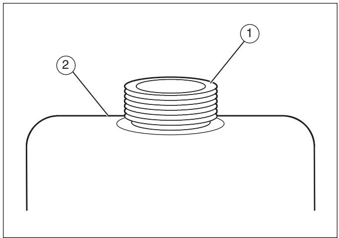
Figure 6
Start the Engine

WARNING
The electrical system has an operator presence system that includes a sensor switch for the seat. These components tell the electrical system if the operator is sitting on the seat. This system will stop the engine when the operator leaves the seat. For your protection, always make sure this system operates correctly.
NOTE: The engine will not start unless you depress the clutch/brake pedal and move the blade rotation control to the DISENGAGE position.
- Push the clutch/brake pedal completely forward. Keep your foot on the pedal.
- Move the shift lever to the neutral (N) position.
- Make sure the blade rotation control is in the DISENGAGE position.
- Move the throttle control completely forward to the CHOKE or FAST position. Some models have a separate choke knob. Pull the choke knob to the full CHOKE position.
- Turn the ignition key to the START position.
NOTE: If the engine does not start after four or five tries, move the throttle control to the FAST position. Again try to start the engine. If the engine will not start, see the TROUBLESHOOTING CHART.
- Slowly move the throttle control to the SLOW position.
- To start a hot engine, move the throttle control to a position between FAST and SLOW.
Mowing and Bagging Tips
- For a lawn to look better, check the cutting level of the mower housing. See "Level the Mower Housing" in the Maintenance section.
-
For the mower housing to cut level, make sure the tires have the correct amount of air pressure.
-
Every time you use the unit, check the blade. If the blade is bent or damaged, immediately replace the blade. Also, make sure the nut for the blade is tight.
- Keep the blade(s) sharpened. Worn blades will cause the ends of the grass to turn brown.
- Do not cut or bag grass that is wet. Wet grass will not discharge correctly. Let the grass dry before cutting.
- Use the left side of the mower housing to trim near an object.
- Discharge the cut grass onto the mowed area. The result is a more even discharge of cut grass.
- When you mow large areas, start by turning to the right so that the cut grass will discharge away from shrubs, fences, driveways, etc. After one or two rounds, mow in the opposite direction making left turns until finished.
- If the grass is very high, cut two times to decrease the load on the engine. First cut with the mower housing in the highest position and then lower the mower housing for the second cut.
- For better engine performance and an even discharge of the cut grass, always operate the engine with the throttle in FAST position.
- When you use a bagger, operate the engine with the throttle in FAST position and the shift lever in first or second gear.
- For better cutting performance and a quality cut, mow with the shift lever in one of the slower speeds.
- After each use, clean the bottom and top of the mower housing for better performance. Also, a clean mower housing will help prevent a fire.
| Frequency | Maintenance Required | Comments |
| Daily or before each use | Maintenance engine. | Refer to the Engine Owner's Manual. |
| Examine blade(s). | Check for cracks, wear, and excessive damage. | |
| Remove debris from unit and moving parts. | ||
| Examine all rotating and sliding parts. | ||
| Check tire inflation. | Refer to the Maintenance section. | |
| Verify that the mower housing is level. | Refer to the Maintenance section. | |
| Examine V-belts. | Check for cracks, wear, and excessive damage. | |
| Check brake operation. | Refer to the Engine Owner's Manual. | |
| After completion of first 5 hours | Change oil. | Refer to the Engine Owner's Manual. |
| After 25 hours | Maintenance engine. | Refer to the Maintenance section. |
| Remove, examine, sharpen, and balance blade(s). | Refer to the Maintenance section. | |
| Check adjustments: a. Blade Rotation Control b. Brake c. Clutch d. Steering. | Refer to the Maintenance section. | |
| Lubricate chassis and mower housing. | Refer to Where to Lubricate instructions. | |
| Check the muffler: a. Torque b. For wear or burn out c. Condition of spark arrester (if applicable). | Refer to the Maintenance section. | |
| Before storage of 30 days or more | Prepare engine for storage. | Refer to the Engine Owner's Manual. |
| Drain fuel system. | Refer toWarnings in Owner's Manual. | |
| Add fuel stabilizer. | Refer to the Engine Owner's Manual. | |
| Prepare battery for storage: a. Remove from unit. b. Fully charge. c. Move to cool dry place. |
General Recommendations
- The owner's responsibility is to maintain this product. This will extend the life of the product and is also necessary to maintain warranty coverage.
- Check the spark plug, drive brake, lubricate the unit, and clean the air filter once a year.
- Check the fasteners. Make sure all fasteners are tight.
- Follow the Maintenance section to keep the unit in good operating condition.

WARNING
Before you make an inspection, adjustment, or repair to the unit, disconnect the wire to the spark plug. Remove the wire from the spark plug to prevent the engine from starting by accident.
NOTE: Torque is measured in foot pounds (metric Nm). This measurement describes how tight a nut or bolt must be. The torque is measured with a torque wrench.
Inspect the Blade

WARNING
Before you inspect or remove the blade, disconnect the wire to the spark plug. If the blade hits an object, stop the engine. Check the unit for damage. The blade has sharp edges. When you hold the blade, use gloves or cloth material to protect your hands.
If you keep the blade (1) sharp and inspect the blade for damage, the blade will cut better and be more safe to operate (see Figure 7). Frequently check the blade for excessive wear, cracks, or other damage.
Frequently check the nut (3) that holds the blade (1). Keep the nut (3) tight. If the blade hits an object, stop the engine. Disconnect the wire to the spark plug. See if the blade is bent or damaged. Check the blade adapter (5) for damage.
Before you operate the unit, replace damaged parts with original equipment parts. See the authorized service center in your area. Every three years, have an authorized service person inspect the blade or replace the old blade with an original equipment part.
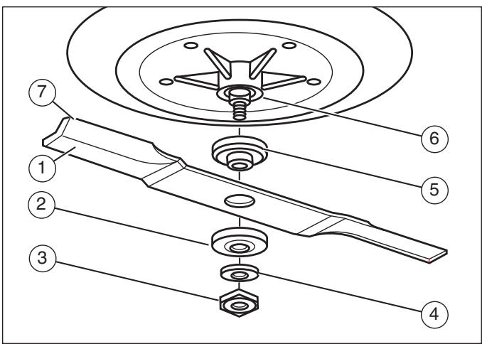
Figure 7
Remove and Install the Blade
- Remove the mower housing. See the instructions to "Remove the Mower Housing."
- Use a piece of wood to keep the blade from rotating.
- Remove the nut (3) that holds the blade (1) (see Figure 7).
- Check the blade and the blade adapter (5) according to the instructions for "Inspect Blade." Replace a badly worn or damaged blade with an original equipment blade. See an authorized service center in your area.
- Clean the top and bottom of the mower housing. Remove all the grass and debris.
- Mount the blade and blade adapter (5) on the mandrel (6).
- Mount the blade so that the hi-lift edges (7) are up. If the blade is upside down, the blade will not cut correctly and can cause an accident.
- Fasten the blade with the original washers and nut (3). Make sure the outside rim of the Belleville washer (2) is against the blade.

WARNING
Always keep the nut (3) tight that holds the blade (1). A loose nut or blade can cause an accident.
- Tighten the nut (3) that holds the blade to a torque of 30 foot pounds (41,5 Nm).
- Install the mower housing. See "Remove the Mower Housing."
Adjust the Blade Rotation Control

WARNING
To prevent an injury, the blade rotation control must operate correctly.
In normal usage, the blade rotation control will not require an adjustment. However, it the cutting performance decreases or the quality of cut is poor, make the following changes.
- When you mow, make sure the throttle control is in the FAST position.
- Move the blade rotation control to the DIS-ENGAGE position (1) (see Figure 8).
- Stop the engine. Disconnect the wire from the spark plug.
- Check the blade(s). Keep a sharp edge on the blade(s). A blade that is not sharp will cause the tips of the grass to become brown.
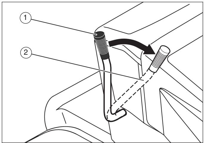
Figure 8
- Disconnect the blade drive spring (2) from the blade control rod (1) (see Figure 9). Move the blade drive spring (2) to the middle hole (4). This will increase the tension on the mower drive belt.
- Attach the wire to the spark plug. Mow for a short distance and again check the quality of cut. If necessary, move the blade drive spring (2) to the bottom hole (5).
- Again check the quality of cut. If the quality of cut has not improved, replace the mower drive belt. See "Replace the Mower Drive Belt." If replacing the belt does not correct the problem, take the unit to an authorized service center.
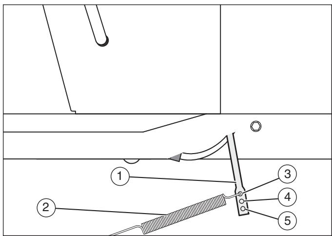
Figure 9
- Move the blade rotation control to the DIS-ENGAGE position. Stop the engine.
- Check the operation of the blade brake. Rotate the pulleys with your hand. Make sure the brake pads (7) are pressed tightly against the pulleys (see Figure 10).

WARNING
If the brake pads (7) do not press tightly against the pulleys, take the unit to an authorized service center.
- Move the blade rotation control to the ENGAGE position (2) (see Figure 8).
- Check the pads for the blade brake (7) (see Figure 10). If the pads are excessively worn or damaged, replace the brake pad assemblies. Correct replacement parts and assistance are available from an authorized service center.
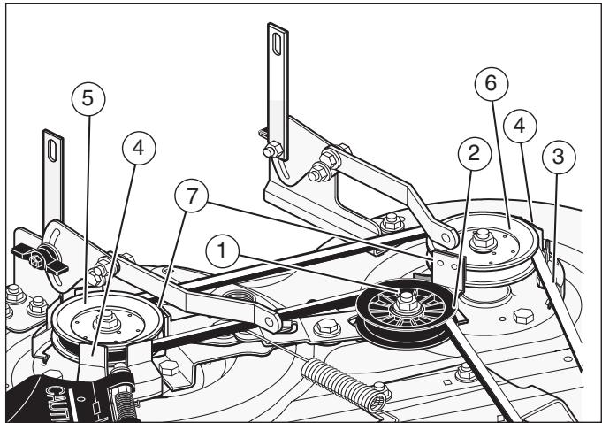
Figure 10
- Attach the wire to the spark plug. Mow for a short distance and again check the operation of the blade rotation control.
- When you move the blade rotation control to the DISENGAGE position, all movement will stop within five seconds. If there is movement of the belt or the blades continue to rotate, engage and disengage the blade rotation control five times to remove any excess rubber from a new mower drive belt. If you need assistance, take the unit to an authorized service center.
- If you replace the mower drive belt, move the blade drive spring (2) to the top hole (3) (see Figure 9).
Adjust the Shift Lever
If the NEUTRAL position on the shift lever does not match neutral on the gearbox, adjust the shift lever as follows.
- Stop the engine.
- Disconnect the adjuster nut (2) from the shifter bracket (3) (see Figure 18).
- Make sure the shift lever is in the NEUTRAL position.
- Push the unit forward. Make sure the gearbox is in neutral.
- To align the adjuster nut with the hole in the shifter bracket, turn the adjuster nut.
- Connect the adjuster nut to the shifter bracket.
- Make sure the NEUTRAL position on the shift lever matches neutral on the gearbox.
Check and Adjust the Clutch
If the motion drive belt is loose, the clutch will slip when; going up a hill, pulling a heavy load, or the unit will not move forward. Adjust the clutch as follows.

WARNING
Before you make an inspection, adjustment, or repair to the unit, disconnect the wire to the spark plug. Remove the wire from the spark plug to prevent the engine from starting by accident.
- Check the routing of the motion drive belt. Make sure the belt is installed correctly and is inside all the belt guides.
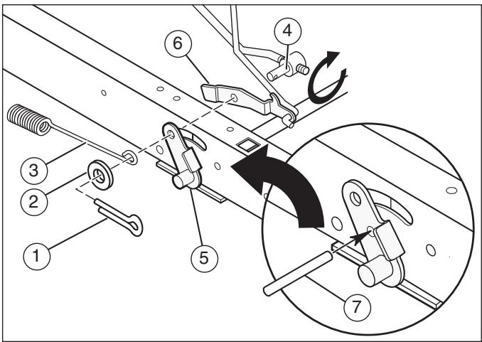
Figure 11
- Remove the cotter pin (1), washer (2), and brake spring (3) from the adjustable nut (4) (see Figure 11).
- Disconnect the adjustable nut from the brake lever assembly (5) and the parking brake latch (6).
- Align the hole in the brake lever (5) with the hole in the frame. Hold the brake lever in place with a 6 mm pin or bolt (7).
- Pull the clutch rod forward until tight. Turn the adjustable nut until the nut will fit through the hole in the brake lever.
- Assemble the adjustable nut to the parking brake latch, brake lever and brake spring. Fasten with the washer (2) and cotter pin (1).
- Remove the 6 mm pin or bolt.
- If the belt still slips after the clutch has been adjusted, then the motion drive belt is worn or damaged and must be replaced. See "Replace the Motion Drive Belt."
Check and Adjust the Drive Brake
Completely push the clutch/brake pedal forward. Set the parking brake. Move the shift lever to the neutral (N) position. Push the unit. If the rear wheels rotate, adjust or replace the brake pads. Adjust the drive brake as follows.
- The location of the drive brake (1) is on the right side of the gearbox (3) (see Figure 12).
-
Make sure the parking brake is set and the shift lever is in neutral (N). Turn the hex nut (2) in a clockwise direction until the rear wheels do not turn when the unit is pushed forward.
-
Release the parking brake and push the unit. If the unit does not roll, turn the hex nut (2) in a counterclockwise direction until the unit rolls.
- Set the parking brake. Push the unit. If the rear wheels do not turn, the drive brake (1) is correctly adjusted. Release the parking brake.

WARNING
If you cannot correctly adjust the drive brake, replace the brake pads. Correct replacement parts and assistance are available from an authorized service center.
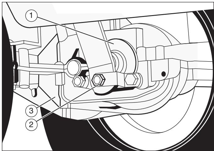
Figure 12
Remove the Battery
To charge or clean the battery (1), remove the battery from the unit as follows (see Figure 4).

WARNING
To prevent sparks, disconnect the black battery cable (8) from the negative (-) terminal before you disconnect the red cable (5).

WARNING
The battery contains sulphuric acid which is harmful to the skin, eyes and clothing. If the acid gets on the body or clothing, wash with water.
- Disconnect the black cable (8) from the negative (-) terminal.
- Disconnect the red cable (5) from the positive (+) terminal (4).
- Lift the battery tray (3) and the battery (1) out of the unit.
Charge the Battery

WARNING
When you charge the battery, do not smoke. Keep the battery away from any sparks. The fumes from the battery acid can cause an explosion.
- Before you charge the battery (1), remove the battery (see Figure 4).
- To charge the battery, use a 12 volt battery charger. Charge at a rate of 6 amps for 1 hour.
- Install the battery.

WARNING
To prevent sparks, fasten the red cable to the positive (+) terminal before you connect the black cable.
- Fasten the red cable (5) to the positive (+) terminal (4) with the fasteners as shown.
- Fasten the black cable (8) to the negative (-) terminal with the fasteners as shown.
Level the Mower Housing
If the mower housing is level, the blade will cut easier and the lawn will look better.

WARNING
Before you make an inspection, adjustment, or repair to the unit, disconnect the wire to the spark plug. Remove the spark plug wire to prevent the engine from starting by accident.
- Make sure the unit is on a hard flat surface.
- Check the air pressure in the tires. If the air pressure is incorrect, the mower housing will not cut level. Make sure the tires are inflated to: Front Tires 0,97 BAR (14 PSI), Rear Tires 0,69 BAR (10 PSI).
- Move the lift lever (1) to the lowest cut position (2) (see Figure 13).

WARNING
The lifter lever (3) is spring loaded. Make sure the lift lever (3) is locked in the lowest cut position (2).
- Loosen the left and right adjuster knobs (1) (see Figure 14). Push down on each side of the mower housing. Make sure both sides of the mower housing are setting on a flat surface. Also, make sure the lift links are loose and can easily move up or down.
- Push down on the lift links (2) and tighten the left and right adjuster knobs. Make sure the adjuster knobs are tight. If necessary, use a wrench to tighten the adjuster knobs.
- Raise the lift lever (1) (see Figure 13).
- Mow for a short distance. If the height of cut is not level, repeat the above steps.
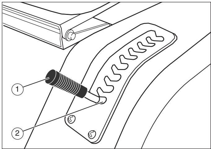
Figure 13
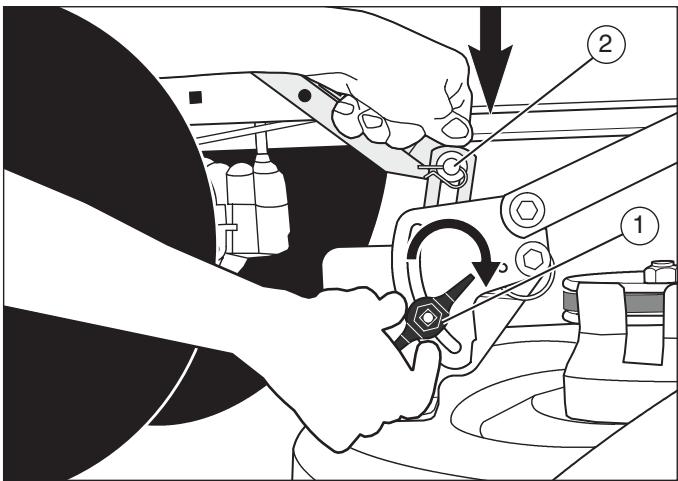
Figure 14
Where to Lubricate

Models with grease fittings: Lubricate with grease gun (see Figure 15).
Apply grease with a brush to the areas shown.
Lubricate the areas shown with engine oil.
NOTE: Apply grease to the steering gear assembly.
CAUTION: If the unit is operated in dry areas that have sand, use a dry graphite spray to lubricate the unit.
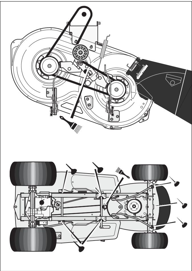
Figure 15
Check the Tires
Check the air pressure in the tires. Tires with too much air pressure will cause the unit to ride rough. Also, the wrong air pressure will keep the mower housing from cutting level. The correct air pressure is: Front Tires 0,97 BAR (14 PSI), Rear Tires 0,69 BAR (10 PSI).
Replace the Motion Drive Belt
- Remove the mower housing. See the instructions to "Remove the Mower Housing."
- Completely push the pedal forward and engage the parking brake.
- Remove the idler pulley (1) (see Figure 16).
- To access the belt guides (1), remove the battery and battery tray (see Figure 17). See "Remove the Battery."
- Loosen the belt guides (1) at the drive pulley (2).
- Remove the motion drive belt (3) from the drive pulley (4) (see Figure 16).
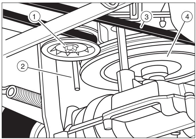
Figure 16
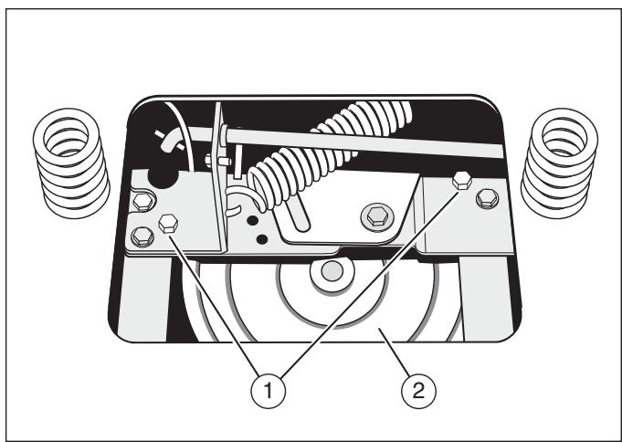
Figure 17
- Remove the adjuster nut (2) from the shifter bracket (3). Pull the motion drive belt over the shifter bracket (3) (see Figure18).
- To remove the motion drive belt (1) from the stack pulley (2), pull the front end of the belt under the stack pulley and then back between the stack pulley and the steering plate (3) (see Figure 19).
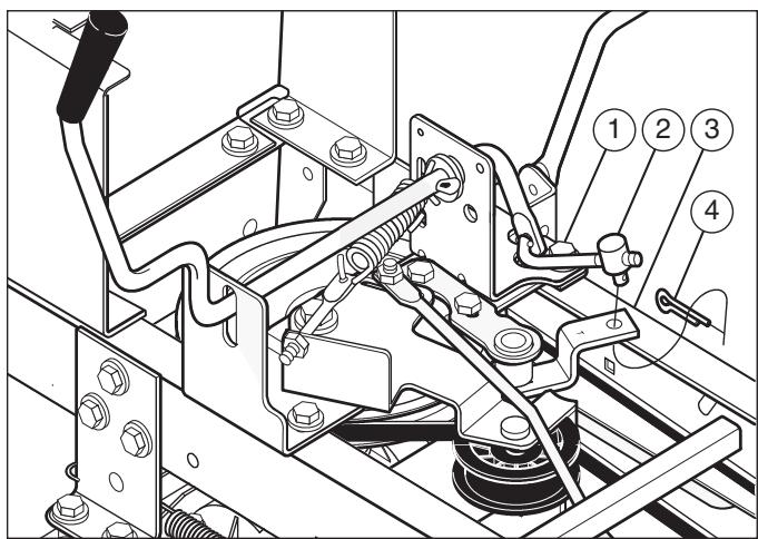
Figure 18
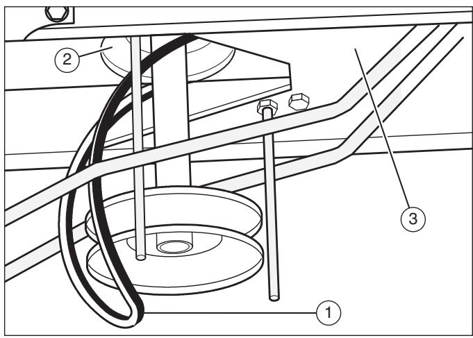
Figure 19
- Remove the access panel (1) (see Figure 20).
- Remove the two screws (4) that attach the steering shaft assembly. Raise the steering wheel and steering shaft assembly. Pull the motion drive belt (3) under the steering shaft assembly.
- Remove the motion drive belt. A correct replacement part or assistance is available from an authorized service center in your area.
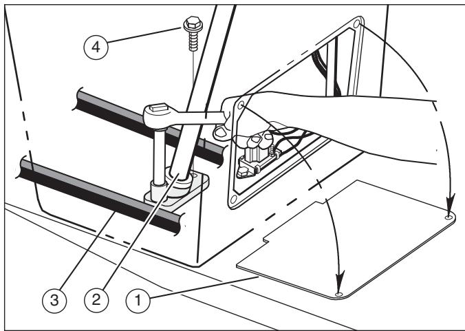
Figure 20
- To install the motion drive belt, reverse the above steps.
- Check the routing of the motion drive belt (1) (see Figure 21). Make sure the motion drive belt is installed correctly on the idler pulley (2). Make sure the steering shaft assembly (3) is inside the motion drive belt.
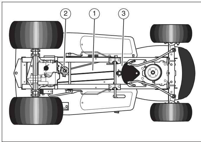
Figure 21
Replace the Mower Drive Belt
- Remove the mower housing. See the instructions to "Remove the Mower Housing."
- Pull the belt retainer (1) away from the idler pulley (2) and remove the mower drive belt (3) (see Figure 10).
- Pull the belt retainer (4) away from the right mandrel pulley (5) and remove the mower drive belt (3).
- Pull the belt retainer (4) away from the left mandrel pulley (6) and remove the mower drive belt (3). A correct replacement part or assistance is available from an authorized service center in your area.
- To install the mower drive belt, reverse the above steps.
Remove the Mower Housing
- Move the blade rotation control (1) to the DIS-ENGAGE position (see Figure 22).
- Move the lift lever (2) to the level adjustment position.
- Remove the hair pins and the washers from the adjuster arms (3). See illustrations "C" and "D".
- Remove the hair pins and washers from the suspension links (4). See illustrations “A” and “B”.
- Disconnect the extension spring (5) from the blade control rod (6). See illustration "E".
- Disconnect the front hanger (9) from the axle support. See illustration “F”.
- Remove the mower drive belt (7) from the stack pulley (8).
- Pull the mower housing away from the right side of the unit.
- To install the mower housing, reverse the above steps.
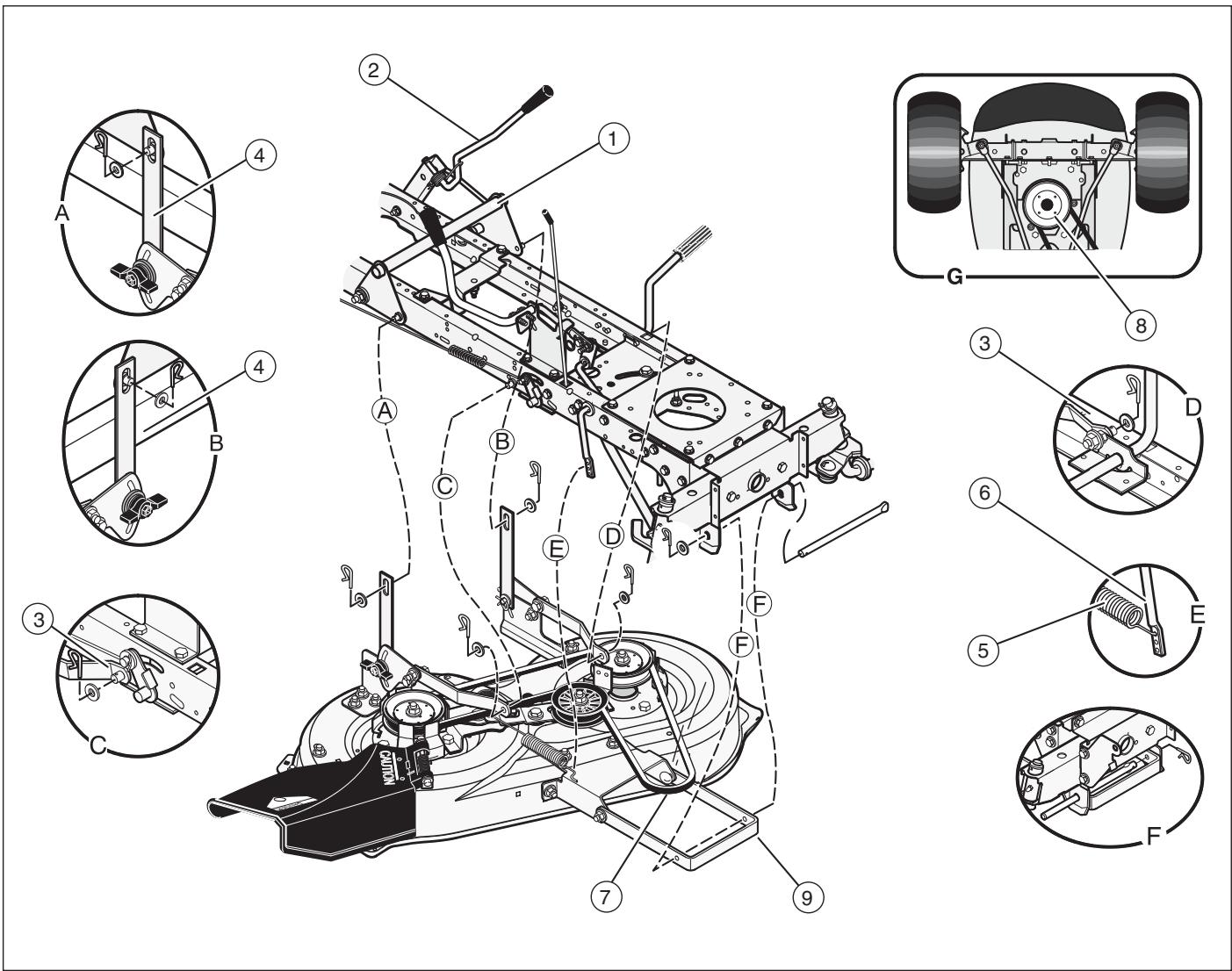
Figure 22
Replace the Fuse
If the fuse is blown, the engine will not start. Remove the fuse and replace with a 15 amp automotive fuse.
Storage (over 30 days)
At the end of each year, prepare the unit for storage as follows.
- Drain the fuel from the carburetor and the fuel tank. Change the engine oil. See the engine manufacturer's instructions.
- Clean the entire unit.
- Charge the battery.
Order Replacement Parts
The replacement parts are shown either on the back pages of this Instruction Book or in a separate Parts List Book.
Use only manufacturer's authorized or approved replacement parts. Do not use attachments or accessories not specifically recommended for this unit. In order to obtain proper replacement parts you must supply the model number of your mower (see nameplate).
Replacement parts, except for the engine, transmission, transaxle or differential, are available from the store where the mower was purchased or a service shop recommended by the store.
Warranty service is available only through Authorized Service Dealers. Locate your nearest dealer in our locator map at www.murray.com.
Replacement parts for the engine, transaxle, or transmission, are available from the manufacturer's authorized service center found in the commercial pages of the telephone directory. Also, see the individual engine or transmission warranties to order replacement parts.
When ordering the following information is required:
(1) Model Number
(2) Serial Number
(3) Part Number
(4) Quantity
| Problem | Solution |
| The engine will not start. | 1. Follow the steps, “Start the Engine” in this book. |
| 2. Electric-Start Models: Clean the battery terminals. Tighten the cables. | |
| 3. Check for a loose wire. Tighten the limit switches. (See the wiring diagram.) | |
| 4. Drain the fuel tank. Clean the fuel line. Replace the fuel filter. | |
| 5. Remove the spark plug(s). Move the throttle to the SLOW position. Turn the ignition key to the ON position. Try to start the engine several times. Install the spark plug. | |
| 6. Replace the spark plug. | |
| 7. Adjust the carburetor. | |
| The engine will not turn over. | 1. Follow the steps, “To Start the Engine” in this book. |
| 2. Electric-Start Models: Charge the battery. | |
| 3. Replace the fuse. | |
| 4. Check the wiring harness for damage or a loose connection. Repair the damaged wire. | |
| 5. Electric-Start Models: replace the solenoid. Recoil-Start Models: replace the module. | |
| The engine is difficult to start. | 1. Adjust the carburetor. |
| 2. Replace the spark plug. | |
| 3. Replace the fuel filter. | |
| The engine does not run smooth or has a loss of power. | 1. Check the oil. |
| 2. Clean the air filter. | |
| 3. Clean the air screen. | |
| 4. Replace the spark plug. | |
| 5. The engine is working too hard. Use a lower gear. | |
| 6. Adjust the carburetor. | |
| 7. Replace the fuel filter. | |
| The engine does not run smooth at fast speed. | 1. Replace the spark plug. |
| 2. Adjust the throttle control. | |
| 3. Clean the air filter. | |
| 4. Replace the fuel filter. | |
| The engine stops when the blades are engaged. | 1. Check the wiring harness for damage or a loose connection. Repair the damaged wire. |
| 2. Grass bag must be installed (applies only to model with rear discharge grass bag). | |
| On slopes, the engine stops. | 1. Mow up and down slopes. Never mow across a slope. |
| The engine will not idle. | 1. Replace the spark plug. |
| 2. Clean the air filter. | |
| 3. Adjust the carburetor. | |
| 4. Adjust the throttle control. | |
| 5. Drain the fuel tank. Clean the fuel line. Replace the fuel filter. | |
| A hot engine causes a decrease in power. | 1. Clean the air screen. |
| 2. Check the oil. | |
| 3. Adjust the carburetor. | |
| 4. Replace the fuel filter. | |
| Excessive vibration. | 1. Replace the blade. |
| 2. Check for loose engine bolts. | |
| 3. Decrease the air pressure in the tires. | |
| 4. Adjust the carburetor. | |
| 5. Check for a damaged belt or damaged pulley. Replace the damaged parts. | |
| The grass does not discharge correctly. | 1. Stop the engine. Clean the mower housing. |
| 2. Raise the height of cut. | |
| 3. Replace or sharpen the blade(s). | |
| 4. Move the shift lever to a lower speed. | |
| 5. Move the throttle control to the FAST position. | |
| 6. Replace the spring for the blade idler. | |
| 7. Clean the extension tube and the connector tube (applies only to model with rear discharge grass bag). | |
| The mower housing does not cut level. | 1. Check the air pressure in the tires. |
| 2. Adjust the level of the mower housing. | |
| 3. Check the front axle. If the front axle does not freely pivot, loosen the axle bolt(s). | |
| The mower blades will not rotate. | 1. Check the mower drive belt. Make sure the belt is installed correctly. |
| 2. Replace the mower drive belt. | |
| The unit will not move when the clutch is engaged. | 1. Check the motion drive belt. Make sure the belt is installed correctly. |
| 2. Adjust the clutch. | |
| 3. Replace the motion drive belt. | |
| The unit moves slower or stops when the clutch is engaged. | 1. Adjust the clutch. |
| 2. Replace the motion drive belt. | |
| When the clutch/brake pedal is released, belt noise can be heard. | 1. Temporary belt noise does not change the operation of the unit. If belt noise is continuous, check the routing of the belt. Make sure the belt is inside all belt guides. |
| 2. If the noise is continuous, adjust the clutch. | |
| The rear wheels spin over uneven terrain. | 1. Check the front axle. If the front axle does not freely pivot, loosen the axle bolt(s). |
| The transaxle is difficult to shift between gears with the engine running and the clutch depressed. | 1. Check the clutch adjustment to make sure the belt stops when the clutch pedal is depressed with the transaxle in (N) neutral. |
| 2. Check the belt guides around the transaxle drive pulley. Make sure the belt guides do not touch the pulley. |
//MURRAY
INSTRUZIONI PER L'USO
Modello 405021x51A
Product Type
Mfg. No. Description
Model No. 405021x51A
Product Type
Mfg. No. Description
7800279 40” Murray CE Plænetraktor

CAUTION: Read and
follow all instructions.
Manual Part No. 7101969
Revision 00
Rev. Date 01/2008
TP 199-4811-00-RD-R
Internationale Illustrationer 60
Begraenset Garanti 61
Information til Ejeren 62
Sikker Brug. 63
Samling at Plaenetraktoren 65
Brug af Plaenetraktoren 67
Before Starting the Engine
Kontroller olien
Opbevaring (over 30 dage)
Ved aflsutnig af brug for aret, folg fologende procedure for opbevaring af plaenetraktoren.
Model No. 405021x51A
Product Type
Mfg. No.
7800279
Description
40” Murray CE Rider

CAUTION: Read and
follow all instructions.
Manual Part No. 7101969
Revision 00
Rev. Date 01/2008
TP 199-4811-00-RD-R
If the NEUTRAL position on the shift lever does not match neutral on the gearbox, adjust the shift lever as follows.
- Slå av motoren
- Kople justeringsmutteren (2) fra skiftebraketten (3) (figur 18).
- Undersøk at girspaken står i NEUTRAL (fri).
- Skyv encheten forover. Kontroller at girboksen er i fri.
- Skru justeringsmutteren for Å stille den på linje med hullet i skiftebrakketten.
- Kople justeringsmutteren til skiftebraketten.
- Kontroller at stillingen NEUTRAL (fri) på girspaken på stemmer overens med fri på girboksen.
Modell No. 405021x51A
Product Type
Mfg. No.
7800279
Description
follow all instructions.
Manual Part No. 7101969
Revision 00
Rev. Date 01/2008
TP 199-4811-00-RD-R
Internationella Symboler 116
Begransad Garanti 117
Information Till Agaren 118
Rutiner For Saker Drift 119
Montering. 121
Drift. 123
Underhalskort 127
Underhäll 128
Model No. 405021x51A
Product Type
Mfg. No. Description
7800279 40" Murray CE Braucošs Plăveja

CAUTION: Read and
follow all instructions.
Manual Part No. 7101969
Revision 00
Rev. Date 01/2008
TP 199-4811-00-RD-R
Starptautiskie Illustrativie Apzimejumi 144
Ierobežota Garantija 145
Informacija Ipašniekam. 146
Droši Darba Panēmieni 147
Montaza 149
Eksplatacija 151
Apkopes Diagram 155
Apkope 156
Bojajumu Nover'sanas Shema 165


BRIGGS & STRATTON CORPORATION, IPASNIKGA GARANTIJAS POLISE
If the brake pads (7) do not press tightly against the pulleys, take the unit to an authorized service center.
- Virziet asmens rotacijas vadibu uz ENGAGE sta vokli (2) (Attels 8).
- Pärbaudiet paliktnus prieks asmens bremzes (7). Ja paliktni ir loti nodilusi vai bojati, nomainiet bredzu paliktnu mezglus (Attels 10). Pareizas rezerves dalas un palidziba ir sanemama no autorizeta servisa centra.

Attels 10