
X-65F PRO FLIGHT COMBAT CONTROL SYSTEM - Joystick SAITEK - Free user manual and instructions
Find the device manual for free X-65F PRO FLIGHT COMBAT CONTROL SYSTEM SAITEK in PDF.
| Product Type | Joystick with Throttle and Switch Panel |
| Brand | Saitek (a Mad Catz brand) |
| Model | X-65F Pro Flight Combat Control System |
| Technology | Force Sensing (no moving parts on stick) |
| Axes | X, Y, Rudder (twist); Throttle 1, Throttle 2, Rotary 1, Rotary 2 |
| Buttons (Stick) | 8 buttons, 1 hat switch (4-way) |
| Buttons (Throttle) | 4 buttons, 1 hat switch (4-way), mouse nipple, scroll wheel |
| Switch Panel | 4 T-buttons, safe cover button, mode lights, 4 force setting buttons (F1-F4) |
| Modes | 4 mode positions (controlled by slider on throttle) |
| Force Settings | 4 pre-sets (F1 strongest to F4 lightest), adjustable for X, Y, Rudder axes (kgf/lbf/N*m/ft*lbs) |
| Deadzone Adjustment | Per axis, plus axis enveloping (X, Y, Rudder) |
| Connectivity | USB 2.0 (cable included) |
| Power Source | USB bus-powered |
| Compatible Operating Systems | Windows XP (32/64-bit), Windows Vista (32/64-bit), Windows 7 (32/64-bit) |
| Programming Software | Smart Technology (ST) Programming Software (included on CD) |
| Profile Storage | Custom profiles can be saved and activated |
| Warranty | 2 years from date of purchase (with proof of purchase) |
| Regulatory Compliance | FCC Part 15 Class B, Canadian ICES-003 |
| Maintenance & Cleaning | Wipe with dry cloth; avoid liquids and abrasives |
| Spare Parts / Repairability | Contact authorized service center or Mad Catz support |
Frequently Asked Questions - X-65F PRO FLIGHT COMBAT CONTROL SYSTEM SAITEK
User questions about X-65F PRO FLIGHT COMBAT CONTROL SYSTEM SAITEK
0 question about this device. Answer the ones you know or ask your own.
Ask a new question about this device
Download the instructions for your Joystick in PDF format for free! Find your manual X-65F PRO FLIGHT COMBAT CONTROL SYSTEM - SAITEK and take your electronic device back in hand. On this page are published all the documents necessary for the use of your device. X-65F PRO FLIGHT COMBAT CONTROL SYSTEM by SAITEK.
USER MANUAL X-65F PRO FLIGHT COMBAT CONTROL SYSTEM SAITEK
Programming With Smart Technology Software 13
Troubleshooting 18
Technical Support 18
François
Commencer l'installation. 20
Support Technique 25
Deutsch
Beginn 37
In order for this product to function correctly, please install the drivers on the CD supplied with this product.
Drivers and Software installation for users of Windows® XP, 32-and 64-bit
A) Drivers Only Installation
- With your computer switched on, close down any programs that are currently running and insert the Installation CD into your CD-ROM drive.
- When the Introduction Screen appears, click Install Software to continue. If the CD does not run automatically, select Start from the Windows® Taskbar, then Run and type D:\Setup.exe and click OK - where D:\ is the letter of your CD-ROM drive.
- When the Welcome screen appears, click Next to continue.
- After reading the Disclaimer, select the I accept the terms of the Disclaimer option and click Next to continue.
- At the Driver Setup screen, if you haven't already done so, plug the USB cable into one of your computer's USB ports and click on Next.
- At the Driver Setup screen, click Next to test your controller.
- When the Saitek Controller screen appears, try out all your controller's buttons and controls to determine if it is working properly. When you have finished, click OK.
- At the Software Setup screen, select Do not install the ST Programming Software and click Next. The Programming Software can be installed at a later date by following instruction (B). below
- At the Registration screen, select Check this box to register now and follow the on-screen instructions, or you can choose to select this option later.
- Click on Finish to complete the installation.
B) Drivers and Programming Software For Advanced Users
- Follow points 1 to 8 of the install procedure in A), then at the Software Setup screen, select Install the SST Programming Software and click Next.
- In the following Software Setup screen, click Next and follow the on-screen instructions. At this point you will be asked to install such features as the Saitek Magic Mouse, HID-compliant mouse, Saitek Magic Keyboard and HID Keyboard Device (these are what XP calls the various elements of your Saitek programming software). Continue to click on Next and Finish to accept the installation until the Registration screen appears.
- At the Registration screen, select Check this box to register now and follow the on-screen instructions, or do not select this option and register later.
- Upon completion of the installation, you have the option to Run Profile Editor, which will give you a view of the programming environment. If you do not wish to see the Profile Editor at this point, just uncheck the box and click on Finish to complete the installation.
Drivers and Software installation for users of Windows® Vista and 7, 32-and 64-bit
A) Drivers Only Installation
- With your computer switched on, close down any programs that are currently running and insert the Installation CD into your CD-ROM drive.
- When the Introduction Screen appears, click Install Software to continue. If the CD does not run automatically, select Start from the Windows® Taskbar, then Run and type D:\Setup.exe and click OK - where D:\ is letter of your CD-ROM drive.
- When the Welcome screen appears, click Next to continue.
- After reading the Disclaimer, select the I accept the terms of the Disclaimer option and click Next to continue.
- At the Driver Setup screen, if you haven't already done so, plug the USB cable into one of your computer's USB ports and click on Next.
- At the Driver Setup screen, click Next to test your controller.
- When the Saitek Controller screen appears, try out all your controller's buttons and controls to determine if it is working properly. When you have finished, click OK.
- At the Software Setup screen, select Do not install the SST Programming Software and click Next. The Programming Software can be installed at a later date by following instruction (B). below
- At the Registration screen, select Check this box to register now and follow the on-screen instructions, or you can choose to select this option later.
- Click on Finish to complete the installation.
B) Drivers and Programming Software For Advanced Users
- Follow points 1 to 8 of the install procedure in A), then at the Software Setup screen, select Install the SST Programming Software and click Next.
- In the following Software Setup screen, click Next, a pop-up box will appear asking if you "want to trust software from Saitek". Click yes and click Next – the installation will automatically continue until the Registration screen appears.
- At the Registration screen, select Check this box to register now and follow the on-screen instructions, or do not select this option and register later.
- Upon completion of the installation, you have the option to Run Profile Editor, which will give you a view of the programming environment. If you do not wish to see the Profile Editor at this point, just uncheck the box and click on Finish to complete the installation.
Force Sensing
Your new X65F uses force sensing technology to provide ultimate realism.
Force Sensing means that the X65F stick contains no moving parts, therefore the stick will not move; instead the greater amount of pressure you apply to the stick with your hand the more the stick will respond, if you want to bank hard left you will apply more pressure to the right side of the stick; subsequently if you want to slightly raise the nose of your plane you will apply a little pressure to the front of the stick. The direction of pressure remains the same as a standard joystick so that in no time at all this method will become second nature and you'll see why some of the best known fighters in the world use this method.
CONTROLLER SETTINGS
Your Saitek X65F is supplied ready for use. However, we want you to use it in the way that suits you best. We’ve therefore included the facility for you to change various settings on your stick and throttle units. You can, for example, vary the amount of pressure required to move the force sensing stick or check that your stick is working correctly.
You can change your controller settings in the Pro Flight X65F properties page. There are a number of ways to open this page depending on your operating system.
For Windows XP- 32-and 64-bit versions
Double-click on the Game Controllers icon in the Control Panel and then click Properties in the Game Controllers window that is displayed.
If the SST programming software has been installed, right-click on the Saitek X65F Flight Stick profiler icon in your task bar and select Control Panel from the pop-up list of options displayed.
For Windows Vista and Windows 7 – all versions
- Click on Start, select Games from the start menu, click the tools option from the tabs. From the list under tools click input device, the game controller window will open. Make sure X65F is highlighted by clicking on it then click on the properties icon, or-
- Click on Start, click on devices and printers from the start menu. The X65F icon will appear, right-click and select game controller settings - click on properties in the window that is displayed.
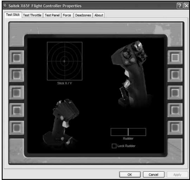
The Pro Flight X65F properties window consists of six separate tabs.
- Test Stick
- Test Throttle
- Test Panel
- Force
- Deadzones
- About
You can view and change various controller settings in each tab. The settings you can change are described in the following sections.
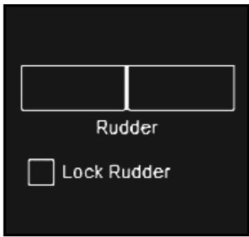
1. Test Stick
The test stick tab allows you test all the functions and features of your X65F stick.
Buttons / Hats
Press any button or use any HAT on your X65F Stick and the corresponding button or HAT direction will light up on the page; this will indicate that the buttons and Hats are working correctly.
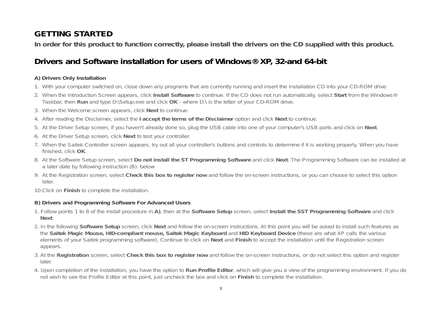
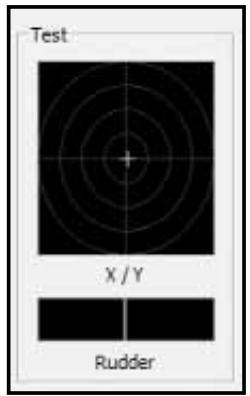
Axis
The X65F stick has 3 axes, an X-axis (Left and Right), a Y-axis (Up and Down) and a Twist or Rudder axis (Twist Stick).
To test the X and Y axes simply place your hand on the stick and apply pressure in the forward / back or left / right motions, or a combination of both. You will see the cross hair, as per the image on the left, moving around the square test area; this indicates the X and Y axes are working correctly.
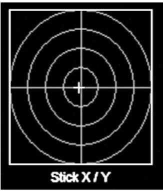
To test the rudder axis, place your hand on the stick and apply pressure to the twist motion of the stick. You will see the green bar in the bottom right of the screen fill up
depending on which way you are applying pressure. This shows the rudder axis is responding correctly.
Checking the Lock Rudder box will stop the rudder on the X65F from responding. This is especially useful if you own a set of rudder pedals – N.B. Pro Flight rudder pedals are available from our website – www.saitek.com.
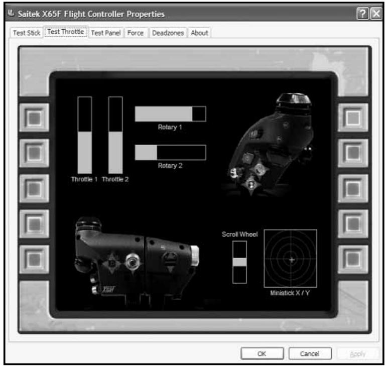
2. Test Throttle
The test throttle tab allows you test all the functions and features of your X65F throttle.
Buttons / Hats
Press any button or use any HAT on your X65F Throttle and the corresponding button or HAT direction will light up on the page; this will indicate that the buttons and HATs are working correctly.
Axis
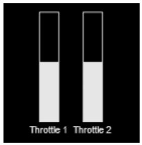
The X65F throttle has 4 axes, the Left Throttle, Right Throttle, Rotary 1 and Rotary 2.
To test the left and right throttle, either move the twin throttles together or move them independently. When moving the throttles the 2 green bars in the top right corner will fill and unfill depending on the throttles' position; with the throttles full forward the bars will be full and with the throttles full back the bars will be empty; this will indicate that the throttles are working correctly.
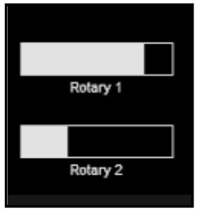
To test the rotaries, move one or both rotaries on the throttle unit; you will see the green rotary bars fill and un-fill on the test page; this indicates your rotaries are working correctly.
Mouse
To test the mouse feature, move the mouse nipple on the throttle unit; the green cross hairs in the bottom right corner should move around the mouse test area; this shows your mouse feature is working correctly.
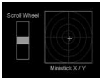
Scroll Wheel
To test the scroll wheel, move the scroll wheel up and down on your throttle unit; in the scroll wheel test area you will see the green bar moving up and down, depending on which way you are moving the wheel: this shows the scroll wheel is working correctly.
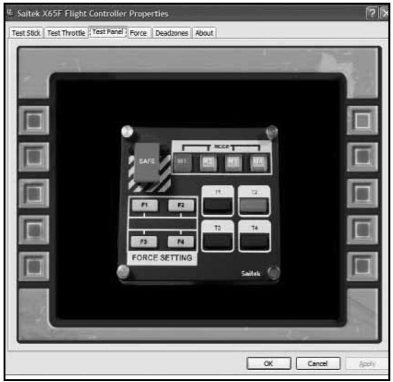
3. Test Switch Panel
The test panel tab allows you test all the functions and features of your X65F Switch Panel.
T-Buttons
The T- Buttons, 1 to 4, are just standard controller buttons; pressing any of the buttons on the switch panel will light the corresponding button in the on-screen image.
Safe Cover / Button
Lifting the safe cover will reveal a lit red button. This button is a standard controller button and can be assigned to any in-game function; pressing the button on the switch panel will light the corresponding button in the on-screen image.
Mode Lights
One of the mode lights will also be lit on the switch panel. These mode lights indicate which "Mode" the controller is currently in. The mode lights directly correspond to the mode slider button that is located on the throttle unit, so if the mode selector is in mode 1 the mode 1 light will be lit on the switch panel; if the mode selector is moved to position 2 the mode light 2 will be lit on the switch panel. This is the same for modes 3 and 4.
Force Settings Button
There are 4 Force setting buttons on the switch panel, labeled F1 to F4. Each one of these buttons indicates the current force setting. By physically pressing the Force buttons the light on the switch panel under that button will light. However it will not light on screen – only 1 Force button can be active at once.
The next section will explain what the default setting for each force is and how to change them to your own personal tastes.
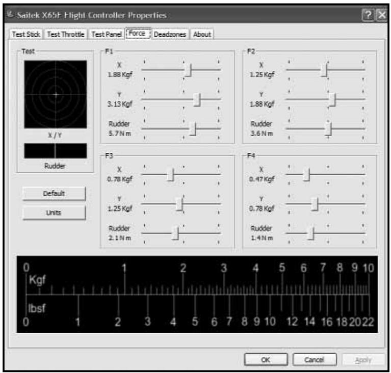
4. Force
The Force tab allows the changing of the 4 pre-set force settings.
When opening the tab you will see 5 main areas, a test area for X, Y and Rudder axes and 4 main adjustment area's labeled F1 to F4.
Test Area
Moving the X, Y or Rudder axes will give feedback in the test area. This test area is similar to the test stick page – it can used as a quick reference when adjusting the Force Settings.
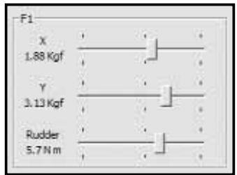
Adjusting Force Settings
There are 4 boxes, labeled F1 to F4, and each of these boxes is directly related to the F1 to F4 buttons on the Switch Panel.
In each box you will see 3 sliders with the labels X, Y and Rudder.
Each of the F1 to F4 boxes will be set to different levels. These are called Default levels, F1 being the strongest setting
going through to F4 which is the lightest setting.
You may wish to change one or all four of the force settings for a particular F key. For example, if you wish to change the settings for the F1 button, simply move the sliders to your desired setting. You will not have to save your settings as these are dynamically updated. As soon as a slider is moved the new settings can be tested by looking at the test area on the left side of the screen and moving the appropriate axis on the stick.
If you decide that you prefer or wish to return to the default settings, simply click the Default button on the left side of the screen just under the test area. You will see that all the settings will jump back to thier original values if they have been changed.
By default, the X and Y axis will be set to Kgf – Kilograms force and the rudder axis will be set to N m – Newton's meters. However if you prefer to see the units in imperial, press the Units button located on the left side of the screen under the test area; the F1 – F4 settings will now change to lbsf (pounds force) for X and Y axes and ft lbs (Feet pounds) for the rudder axis.
For ease of use we have included a conversion table at the bottom of the screen which shows Kgf to lbsf, (Kilograms force to pounds force).
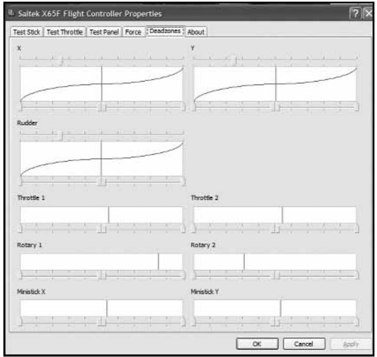
5. Deadzones
This screen is split into 2 main areas, while you can set the deadzone settings on all 7 axes and 2 mouse axes, you can also adjust the axis envelope on the X, Y and Rudder axes. We will explain both of these features, starting with deadzones.
What is a deadzone?
A deadzone is a part of the range in which an axis moves that is not detected by the drivers; it has no effect on the game in progress. It may be around the center point of the axis range, or at either end of the axis range.
You can create deadzones for each of the 7 axes, X, Y, Rudder, Throttle 1, Throttle 2, Rotary 1, Rotary 2, and for your mouse mini stick which has separate bands for left, right, up and down. For example, you may want to move your stick in the X axis only, but find it difficult to avoid moving it in the Y axis as you do so. You can set up a
deadzone in the Y axis so that these minor movements are not detected by the drivers.
To maintain your deadzones.
Each axis is represented by a white box that contains a red line
displaying where the axis is currently sitting. Moving the corresponding axis moves the red line. Use this line to determine exactly where your deadzone must begin and end. Beneath each box is a sliding scale. You can use this to help specify the size of each deadzone.
For each axis (white box) there are 4 arrows that sit directly under the box on a slider (the slider controls on the top of the X, Y and Rudder axes will be explained later), 2 in the middle and 1 at each end. The 2 in the middle are for the center point of the axis and the ones at either end are for the top and bottom of the axis.
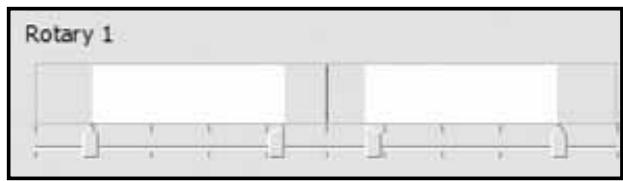
Whilst left-clicking and holding the mouse button down, move the arrow along the slider; you will notice that there are 2 arrows moving along the slider; moving 2 arrows at once will help you to maintain the deadzones correctly. You can drag the arrows to any point you wish. The grey area that appears when you are moving the arrows is known as the deadzone. The image (above, left) shows an example of a rotary that has had the deadzone increased around the center point and at the 2 end points.
If required, you can change the sliders to act independently rather than in pairs, this may be useful if you need a deadzone at the top of an axis but not at the bottom. To do this, right-click anywhere in the white box and select Link Deadzones from the pop-up list displayed. Repeat this to link the pairs of sliders again.
You can clear existing deadzones for an axis by right-clicking anywhere in the white box and selecting Clear Deadzone.
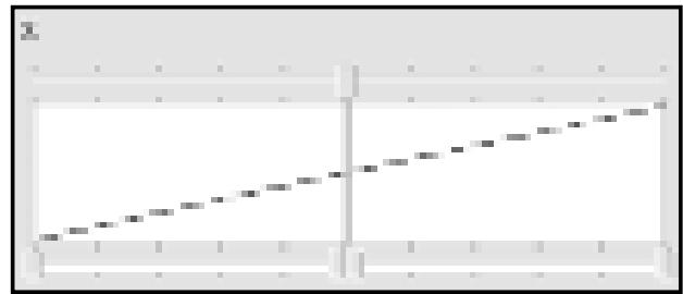
Axis Enveloping
You will see that the X, Y and Rudder axes have a larger axis box than all the other axis boxes and how they have a diagonal line running through them.

The line running from the bottom left to the top right of the box represents the behavior of that axis; for example, if you have the line set as the image on the left, the stick will have the same sensitivity across the whole of the axis range.
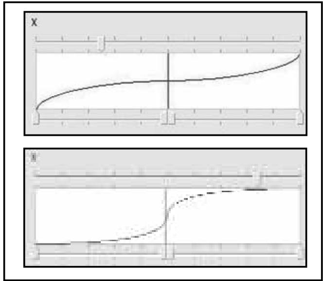
In the 2 examples on the left, the line with the flat middle will mean that the stick will be more sensitive where the curve is steeper at each end of the axis range and less sensitive where the line is flatter around the center point. The example below means that the X axis will be very sensitive around the center and not so sensitive at each end of the axis range.
To move the axis curve, simply drag the arrow that is on the top of the X, Y and Rudder boxes; as you drag the arrow on the slider you will see the curve changing. If you wish to revert back to the standard axis envelope, simply right-click on the arrow and choose Clear Deadzone from the drop down list. The axis line will now go to a straight line.
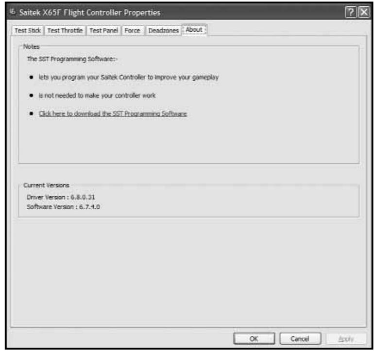
6. About
From the About screen you can see notes on the programming software, which you may or may not have already installed.
You will also see the driver and software version that you have currently installed.
PROGRAMMING YOUR PRO FLIGHT CONTROLLER WITH SMART TECHNOLOGY PROGRAMMING SOFTWARE
Introducing Smart Technology Programming Software
Smart Technology (ST) Programming Software is the software supplied to configure your controller for enhanced functionality. ST delivers a powerful set of features, allowing you to program your device with the ultimate configuration for total interaction. Despite a level of sophistication previously unseen in the market, and because of the Smart Technology inside, the software remains simple and intuitive to use.
Features of Smart Technology Programming Software:
- Quick and easy setup in any game
- Personalize the controller settings for your favorite games
- Configure your controller with an on-screen high-resolution model and interface
- Multiple setup options for each controller - ideal if a controller is used by several people
- Program special moves with sophisticated timing features
- Special game setups available as "Profiles" from the Saitek website and on the Smart Technology CD
- Download the latest version of Smart Technology software from the Saitek website

start the Smart Technology software, either:-
i) Click on Start, then All Programs, then look for Saitek SD6 Programming Software in your list of programs, click on this and under this heading you will see another heading with an icon saying Smart Technology. Click on this and the Smart Technology software will open up.
ii) Look on your desktop for the Smart Technology icon, Once found, double-click and the Smart Technology software will load.
iii) Right-click the controller icon next to your clock, and then click the profile editor. Once the ST software has opened, you will be presented with (if it's the first time you have run the software) a "tip" screen. These screens give useful information pertaining to the profile software. If you do not wish to see these screens when you start the ST software, un-check the small check box in the corner of the tip screen. The tip box can be closed by clicking on the OK icon in the bottom right corner.
Once the tip box has shut down you will be presented with the main screen.
On the Main screen you will see a series of tabs along the top, these are:
- Product
- Settings
- Programming
- Support
Product
The product page is the main screen that appears when the Smart Technology software is first opened.
This screen detects which Pro Flight hardware you have plugged in and shows it on this screen. If you have no Pro Flight hardware plugged in, the Pro Flight Rudder Pedals will appear in the screen. This is because they are first in the list.
Near the bottom center of the page there is a drop down selector box which allows you to alter the controller you wish to change the settings or programming for.
Settings
In the settings tab you can alter the force settings for each of the 4 force sensing buttons, F1 to F4. This is done in a similar way to the Force tab in the Game Controller Settings.
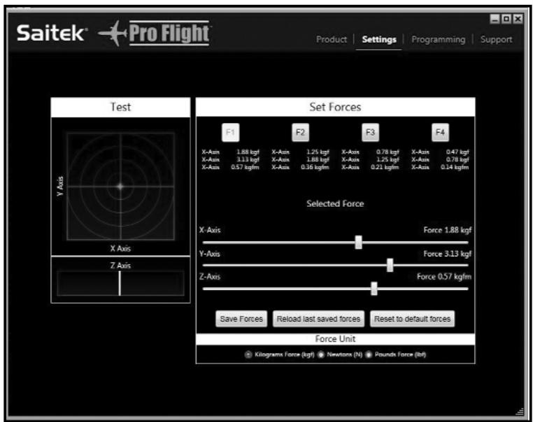
On the left side of the screen is the force test area. This area allows you to test the forces on the X, Y and Rudder axes.
On the right side of the screen is the "Set Forces" area, this area allows you to set your force for each of the force sensing buttons.
You will see 4 buttons, F1 to F4, these are the same buttons that are on your switch panel.
To change a force for any of the buttons, click that button. For example, F2. You can then move the sliders, which are underneath the buttons, to your desired force. You will notice that the actual forces being applied to the stick are registered above each of the sliders.
At the bottom of the screen there is a Force Units icon. Clicking this will scroll through force units that are available to use. These are: Kilograms Force (Kgf), Newtons (N) and Pounds Force (Lbs).
Once the force settings are tested and set to the desired level, click on the Save Forces icon, located just under the sliders. There is also a Reload last saved forces icon which, in case you have made changes to your forces you do not like, will revert your settings to the previously saved settings. The Reset to default forces will reset all forces on the F1 to F4 keys to their default state.
Programming
From the programming tab, you can mimic your controller to directly copy any of your keyboard commands that are used in your favorite games. The commands are then saved in what we call a Profile.
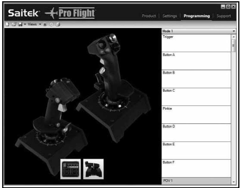
When you click on the programming tab, you will be presented with a high-resolution image of the controller you are going to program on the left, and on the right side of the screen you will see a list of command boxes, called "Cells", going down the page.
What is a Profile?
A profile is the name we call a file that has programmed controller commands saved into it – for example, you may have a Joystick with a number of buttons / hats. If you want one of these to do something in-game that you would normally have to use a keyboard shortcut for, you can “assign” that command to that button. So, if you want button A to activate the landing gear (which is the “g” key), you can assign this in the ST editor. You can of course do more complicated assignments, like “shift+F2” or even timed commands.
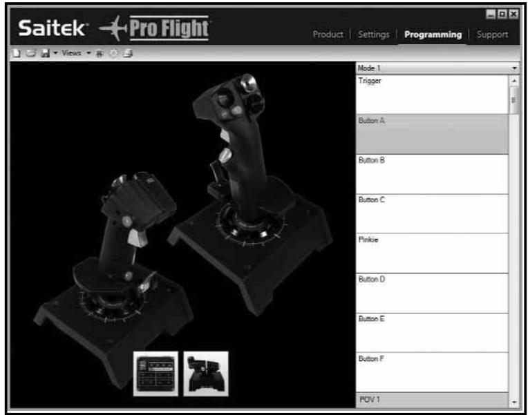
Making your first Profile
- Either hover the mouse pointer over the cell or press the button on the controller you wish to profile, i.e. for the X65F we will use button A on the stick. You will notice that if you hover your mouse over the button A cell, the A button will light up on the 3D joystick image, or if you prefer, just click the A button on the stick and the correct cell will light up 2. When the correct cell is lit, left-click in it, and a large flashing cursor will appear in the cell on the left. There will be a green tick, a red cross and a mouse icon on the right side
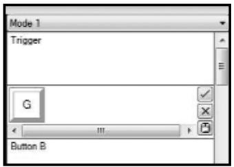
- The cell is now waiting for the keyboard command, using the keyboard, press the button on the keyboard you would like the A button on the stick to activate. For this example we will use the g key, which is normally landing gear. When you press G on the keyboard, a large white tile with the letter G should have appeared in the cell, as shown on the left
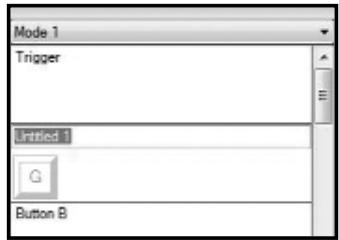
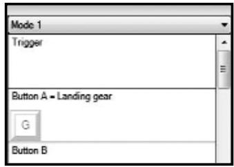
-
If this is the correct keyboard command, press the green tick icon on the right side. If not, press the red cross an go over the procedure to get the keyboard command into the cell again. After pressing the green tick icon, the command name box will appear. At present this will say "Untitled" - left figure top - simply type the name in this box that you want to call the command. For this example type in Landing gear, then press enter and you will now see the cell is complete; Button A = landing gear which is the G key - left image bottom.
-
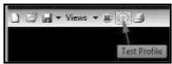
We can now test what we have done by opening the "test window". If you look just above the 3D image there are 7 icons. The 2nd one from the right, which looks like a silver cog, is called Test Profile.
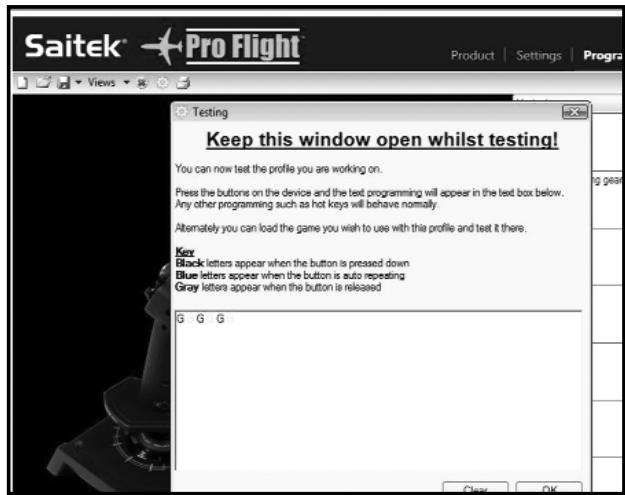
Click on this icon and a new window will open. A cursor will already be flashing in the test area, so all we need to do is to
press the A button on the X65F. When this is pressed you will see the letter G appear in the window, which proves your first programmed button is working.
Shut this window down by clicking on the OK icon in the bottom right corner of the test window.
- You can go on and add other keyboard commands if you wish and then test them; just remember to save your work before you shut the ST Programming editor down.
- To make the programming you have just created work in your game, you must first save it as a profile and then activate it. This can be done with one click – in the icon row which is just above the 3D image, you will see an icon that looks like a blue target. If you hover over this icon, a tool tip will appear saying Profile.
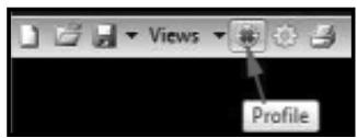
Click this icon and a standard windows save box will appear. Give your profile a name and save it – when you have saved it, the profile will become active. You can now shut the ST software down and play your game and the controller will now respond as you have programmed it.
- There are many other powerful features that we have not covered that the ST programming
software can do. For example, program axes, program mouse movement and mouse buttons, program hats, perform special timed or complicated commands. For a full list of features and full manual please go to the Support tab and click on "Read SST Programming manual."
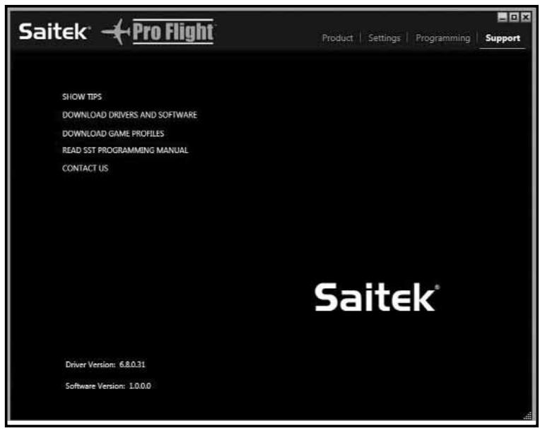
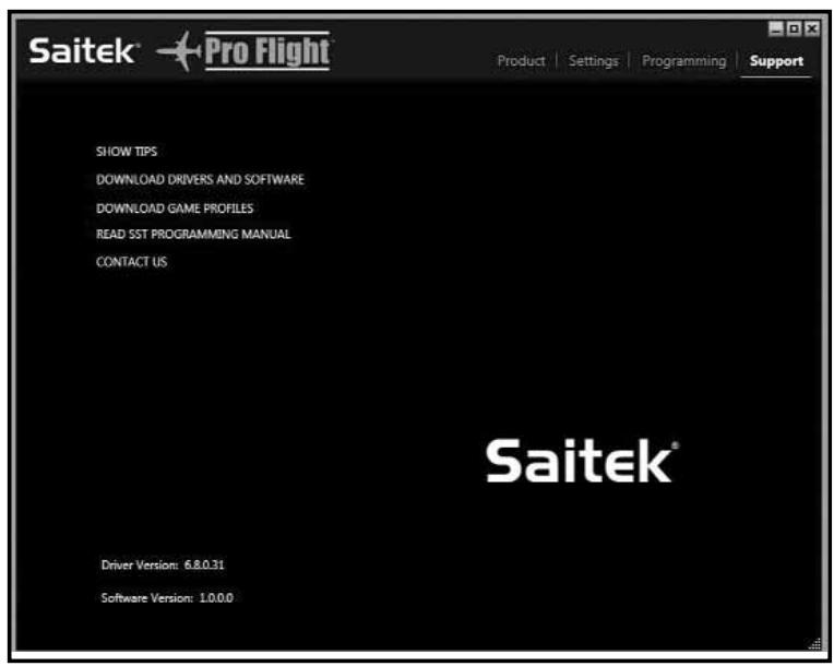
Support
From the support tab you can access the following features by clicking on them:-
- Show Tips
- Download Drivers and Software
- Download Game Profiles
- Read ST Programming Manual
- Contact Us
Show Tips
Once clicked, the tip screen will appear on the screen. This is the same screen that appears the very first time you run the ST software – if desired you can run through all tips from this screen.
Download Drivers and Software
Clicking on this link will open your default browser and direct it at the download drivers and software page.
Download Game Profiles
- Clicking on this link will open your default browser and direct it at the download profiles page. From this page, choose your controller and a list of pre-made profiles will appear that will match all the latest games.
Read ST Programming Manual
The full ST programming manual will open in your default browser window.
Contact Us
Clicking on Contact Us will open your default browser and direct it to the contact information page – from here there is a list of contacts that you can choose from.
TROUBLESHOOTING SECTION
Q My computer is not recognizing the Pro Flight Controller. What's wrong?
A 1. Have you installed the drivers on the CD supplied with this product?
A 2. Check the cable connections. Unplug your controller and plug it back in, making certain that it is securely attached.
A 3. Have you tested your controller? Please refer to the "Controller Settings" section in this manual for further information.
Q2 The game I am playing does not recognize my controller. What's wrong?
A 1. Ensure that you have conducted the checks in Q1 [above].
A 2. Does the game you are playing offer support for game controllers? Please refer to your game manual, this will have information regarding the use of game controllers in the game you are using.
Q3 One of the buttons or axes is not working on my controller.
A 1. Please test your product in the Game controllers panel as mentioned in the early part of this manual.
A 2. If you are still experiencing problems with the controller, please visit the FAQ page which is part of the support section on the Saitek web site.
Q4 My CD is not responding in my CD drive.
A 1. Check for any marks or finger prints on the CD, try to wipe with a dry cloth, if there is still no response please use the "Contact Technical Support" section at the bottom of this Q and A.
Q5 There is a part of my controller which hasn't been included in the box.
A 1. Please contact the retailer who you have purchased from.
Q6 My LEDs are not functioning correctly.
A 1. Ensure that the cables are fully plugged in.
2. Try the controller in a different USB port - N.B. we have noticed that front facing USB ports have shown glitches from time to time, therefore please try a rear USB port if available.
3. If plugging through a non powered USB hub, try plugging the controller directly into the rear of the PC.
4. If available, please try on another PC.
Q7 My axes appear to be off center or moving erratically.
A 1. Please visit the FAQ page which is part of the support section on the Saitek web site. This will give simple instructions on how to reset the calibration. All address are listed in the technical support area in this manual.
TECHNICAL SUPPORT
Can't get your joystick to work? don't worry, we're here to help you!
Nearly all the products that are returned to us as faulty are not faulty at all - they have just not been installed properly. If you experience any difficulty with this product, please first visit our website www.saitek.com. The technical support area will provide you with all the information you need to get the most out of your product and should solve any problems you might have.
If you do not have access to the internet, or if the website cannot answer your question, please contact your local Saitek Technical Support Team. We aim to offer quick, comprehensive and thorough technical support to all our users so, before you call, please make sure you have all the relevant information at hand.
FCC Compliance and Advisory Statement
Warning: Changes or modifications to this unit not expressly approved by the party responsible for compliance could void the user's authority to operate the equipment.
This device complies with Part 15 of the FCC Rules. Operation is subject to the following two conditions:
1 This device may not cause harmful interference, and
2 This device must accept any interference received, including interference that may cause undesired operation.
NOTE: This equipment has been tested and found to comply with the limits for a Class B digital device, pursuant to Part 15 of the FCC Rules. These limits are designed to provide reasonable protection against harmful interference in a residential installation. This equipment generates, uses and can radiate radio frequency energy and, if not installed and used in accordance with the instructions, may cause harmful interference to radio communications. However, there is no guarantee that interference will not occur in a particular installation. If this equipment does cause harmful interference to radio or television reception, which can be determined by turning the equipment off and on, the user is encouraged to try to correct the interference by one or more of the following measures:
- Reorient or relocate the receiving antenna
- Increase the separation between the equipment and receiver
- Connect the equipment into an outlet on a circuit different from that to which the receiver is connected
- Consult the dealer or an experienced radio/TV technician for help
Saitek Industries, 2295 Jefferson Street, Torrance, CA 90501, USA
Canadian EMC statement
This Class B digital apparatus complies with Canadian ICES-003.
You will see that the X, Y and Rudder axes have a larger axis box than all the other axis boxes and how they have a diagonal line running through them.
- Product
- Settings
- Programming
- Support
Product
Making your first Profile
- Show Tips
- Download Drivers and Software
- Download Game Profiles
- Read ST Programming Manual
- Contact Us
Show Tips
Download Drivers and Software
Download Game Profiles
Show Tips
- Download Drivers and Software
Download Game Profiles
- Read ST Programming Manual
- Contact Us
Conditions of Warranty
1 Warranty period is 2 years from date of purchase with proof of purchase submitted.
2 Operating instructions must be followed.
3 Product must not have been damaged as a result of defacement, misuse, abuse, neglect, accident, destruction or alteration of the serial number, improper electrical voltages or currents, repair, alteration or maintenance by any person or party other than our own service facility or an authorized service center, use or installation of nonMad Catz replacement parts in the product or the modification of this product in any way, or the incorporation of this product into any other products, or damage to the product caused by accident, fire, floods, lightning, or acts of God, or any use violative of instructions furnished by Mad Catz .
4 Obligations of Mad Catz shall be limited to repair or replacement with the same or similar unit, at our option. To obtain repairs under this warranty, present the product and proof of purchase (e.g. bill or invoice) to the authorized Mad Catz Technical Support Center (listed on the separate sheet packaged with this product) transportation charges prepaid. Any requirements that conflict with any state or Federal laws, rules and/or obligations shall not be enforceable in that particular territory and Mad Catz will adhere to those laws, rules, and/or obligations.
5 When returning the product for repair, please pack it very carefully, preferably using the original packaging materials. Please also include an explanatory note.
6 IMPORTANT: To save yourself unnecessary cost and inconvenience, please check carefully that you have read and followed the instructions in this manual.
7 This warranty is in Lieu of all other expressed warranties, obligations or liabilities. ANY IMplied WARRANTY, OBLIGATIONS, OR LIABILITIES, INCLUDING BUT NOT LIMITED TO THE IMPLIED WARRANTY OF MERCHANTABILITY AND FITNESS FOR A PARTICULAR PURPOSE, SHALL BE LIMITED IN DURATION TO THE DURATION OF THIS WRITTEN LIMITED WARRANTY. Some states do not allow limitations on how long an implied
warranty lasts, so the above limitations may not apply to you. IN NO EVENT SHALL WE BE LIABLE FOR ANY SPECIAL OR CONSEQUENTIAL DAMAGES FOR BREACH OF THIS OR ANY OTHER WARRANTY, EXPRESS OR IMPLIED, WHATSOEVER Some states do not allow the exclusion or limitation of special, incidental or consequential damages, so the above limitation may not apply to you. This warranty gives you specific legal rights, and you may also have other rights which vary from state to state.
© 2010 Mad Catz Interactive Asia. Mad Catz, the Mad Catz logo, Saitek, Saitek logo and Pro Flight are trademarks or registered trademarks of Mad Catz Interactive Asia., its subsidiaries and affiliates. Saitek is owned by Mad Catz Interactive, Inc., a publicly-listed company, Mad Catz, and the Mad Catz logo are trademarks or registered trademarks of Mad Catz, Inc., its subsidiaries and affiliates. All other trademarks or registered trademarks are the property of their respective owners. Made in China. All rights reserved. Product features, appearance and specifications may be subject to change without notice. Please retain this information for future reference. Mad Catz is a publicly traded company on the TSX/AMEX, symbol MCZ.
Conditions de garantie

- François
- Deutsch
- Drivers and Software installation for users of Windows® XP, 32-and 64-bit
- A) Drivers Only Installation
- B) Drivers and Programming Software For Advanced Users
- Drivers and Software installation for users of Windows® Vista and 7, 32-and 64-bit
- Force Sensing
- CONTROLLER SETTINGS
- For Windows XP- 32-and 64-bit versions
- For Windows Vista and Windows 7 – all versions
- Test Stick
- Buttons / Hats
- Axis
- Test Throttle
- Mouse
- Scroll Wheel
- Test Switch Panel
- T-Buttons
- Safe Cover / Button
- Mode Lights
- Force Settings Button
- Force
- Test Area
- Adjusting Force Settings
- Deadzones
- What is a deadzone?
- To maintain your deadzones.
- Axis Enveloping
- About
- PROGRAMMING YOUR PRO FLIGHT CONTROLLER WITH SMART TECHNOLOGY PROGRAMMING SOFTWARE
- Introducing Smart Technology Programming Software
- Product
- Settings
- Programming
- What is a Profile?
- Making your first Profile
- Support
- Show Tips
- Download Drivers and Software
- Download Game Profiles
- Read ST Programming Manual
- Contact Us
- TROUBLESHOOTING SECTION
- TECHNICAL SUPPORT
- FCC Compliance and Advisory Statement
- Conditions of Warranty
- Conditions de garantie
Brand : SAITEK
Model : X-65F PRO FLIGHT COMBAT CONTROL SYSTEM
Category : Joystick