CAME DIR 10 - Photoelectric cell

DIR 10 - Photoelectric cell CAME - Free user manual and instructions

Find the device manual for free DIR 10 CAME in PDF.

📄 2 pages English EN Download 💬 AI Question 2 questions
Notice CAME DIR 10 - page 1
Pick your language and provide your email: we'll send you a specifically translated version.

User questions about DIR 10 CAME

2 questions about this device. Answer the ones you know or ask your own.

Ask a new question about this device

The email remains private: it is only used to notify you if someone responds to your question.

Why are my CAME DIR 10 photoelectric cells not working and how can I resolve this issue?
Frequently Asked Questions - 26/02/2026
Response Notice-Facile

Several causes may explain the malfunction of your CAME DIR 10 photoelectric cells. Unlike other models, the DIR 10 cells do not require any special intervention for alignment thanks to their integrated optical-electronic circuit, which simplifies troubleshooting. Here are the essential points to check to identify and resolve the issue:

First, check the power supply. The DIR 10 cells operate at 12/24 V AC/DC. Ensure that the correct voltage is reaching the power terminals (marked Rx for the receiver and Tx for the transmitter). Visually inspect the electrical connections at the CAME control panel to determine if there is a cut, disconnection, or a blown fuse. A power supply issue is the most common cause of complete cell malfunction.

Immediately clean the infrared lenses. Even though the cell does not require precise alignment, the lenses must be clear for the infrared beam to function correctly. Check that the lenses are not obstructed by dust, dirt, limescale, or residues. Gently clean the lenses with a soft, dry cloth, without any harsh products. Also, ensure that no physical obstacles (branches, fences, vehicles) block the infrared beam between the transmitter and the receiver.

Inspect the wiring and connections to the control circuit. Examine the cables for cuts, fraying, or signs of mechanical wear. Check that the TX (transmitter) and RX (receiver) connections are properly connected to the correct terminals on the CAME panel (ZA2, ZE3, ZC2, ZH2, or ZR22 depending on your panel model). The DIR 10 cells use a relay contact that must transmit the signal: if this contact is damaged or its range exceeded (1 A max at 24 V), the relay will not close properly.

Check the operating conditions. The DIR 10 cells are guaranteed to operate between -20 °C and +70 °C. If the cells are exposed to extreme temperatures, they may not detect correctly or at all. Also, check that the cell is mounted about 50 cm off the ground, as recommended in the documentation. A positioning that is too high or too low can affect detection.

Test by temporarily disabling the cells. Disconnect the cells from the control circuit and manually restart the gate opening without the cell safety. If the gate operates normally without the cells, the problem lies with the cell itself or its connection. If the problem persists, it is a failure of the control circuit, not the cells. In case of persistent malfunction despite these checks, it is possible that the internal optical-electronic circuit is faulty and the DIR 10 cell needs to be replaced.

Respond (be the first)
What is the wiring diagram for CAME DIR 10 cells to ensure their proper functioning?
Frequently Asked Questions - 28/11/2025
Response Notice-Facile

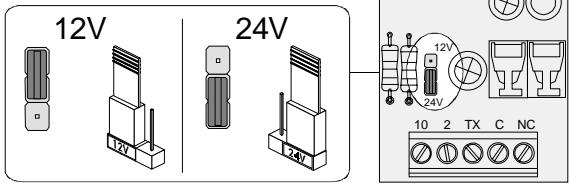
The CAME DIR 10 photoelectric cells consist of a pair of infrared transmitter (TX) and receiver (RX). They do not require any special alignment and should be mounted approximately 50 cm from the ground. The first step is to choose the power supply voltage: 12V or 24V in alternating or direct current depending on your control system. The cells consume 60 mA at 24V a.c. and the relay contact can support a maximum of 1A at 24V.

The wiring depends on your CAME electrical panel. Start by identifying the type of panel (old or new series) to which you are connecting the cells. For the power supply, connect the 12/24V wires (positive and negative) directly to the corresponding terminals of the optical-electronic circuit. The DIR 10 cells have clearly marked terminals on the electronic board for the power supply voltage input.

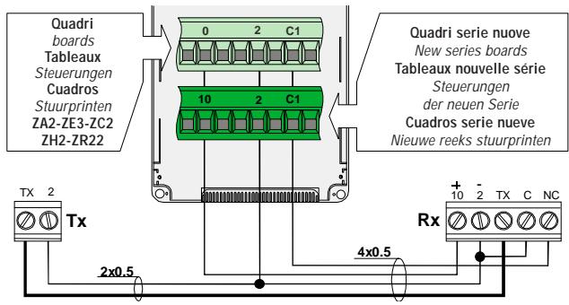
For signal connections, connect the TX and RX outputs to the CAME panel according to the diagram provided in your manual. The relay contact has three terminals: common (C), normally open contact (C or NC). If you want a reopening during closure, use the appropriate configuration indicated in the wiring diagram provided with the cells. The cable connecting the transmitter and receiver must be at least 2×0.5 mm² in section for simple pairs.

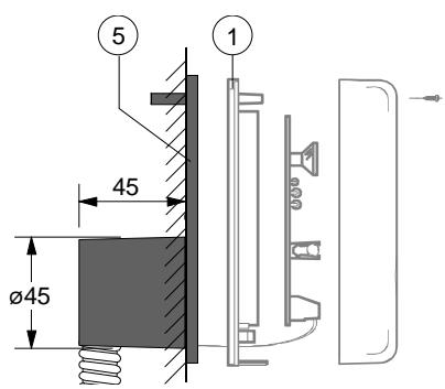
Install the optical-electronic circuit housing (1) on the wall or on the provided mounting base (5), using the supplied fixing screws. Protect the power supply cable by passing it through a suitable conduit to avoid damage. Then mount the infrared screen cover (3) that protects the detector and enhances its robustness against external light interference.

Before commissioning, check that all connections are secure and that the power supply is correct (12V or 24V according to your initial choice). Clean the lenses of the cells with a soft cloth to avoid any obstruction. The cells operate at a range of 10 meters under normal conditions and accept a temperature range of -20°C to +70°C. Restore power and test the operation by interrupting the infrared beam between the transmitter and receiver to verify that the system correctly detects the presence or absence of an obstacle.

Respond (be the first)

Download the instructions for your Photoelectric cell in PDF format for free! Find your manual DIR 10 - CAME and take your electronic device back in hand. On this page are published all the documents necessary for the use of your device. DIR 10 by CAME.

USER MANUAL DIR 10 CAME

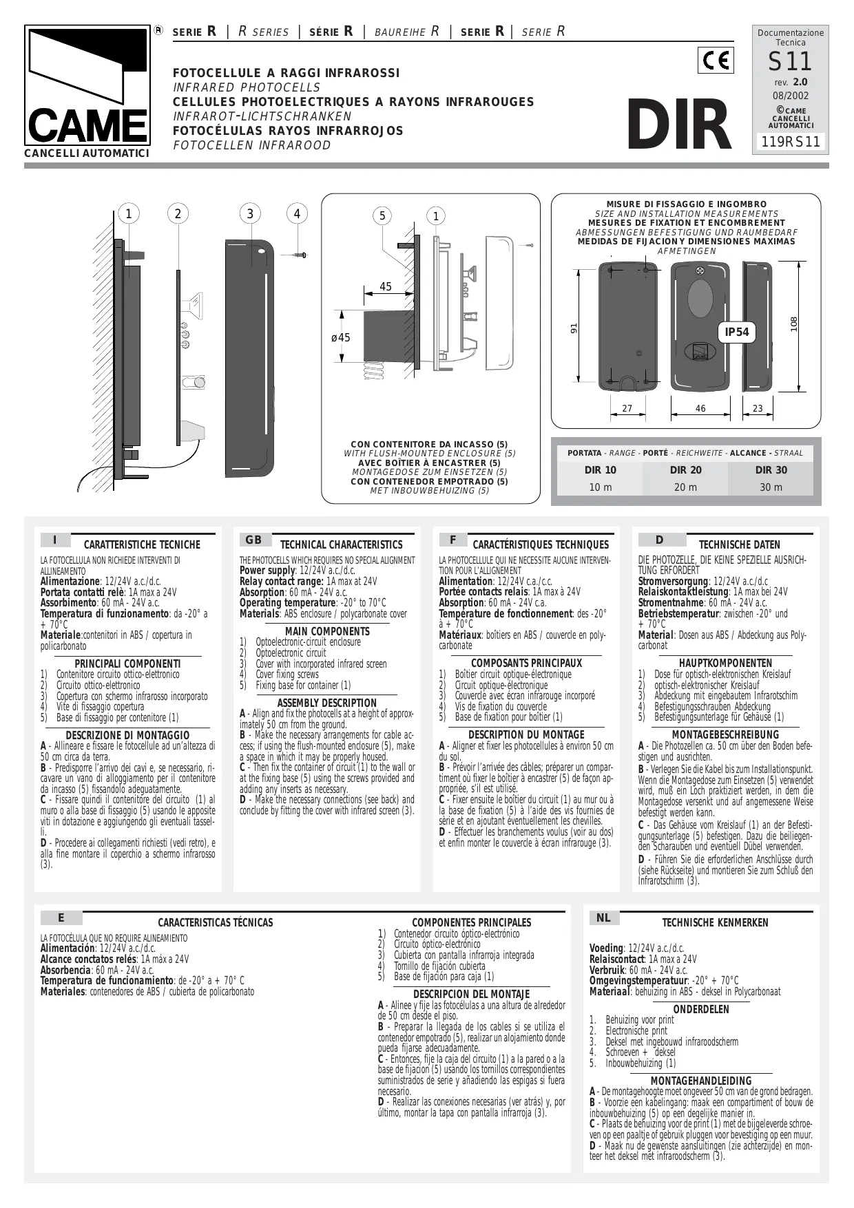
THE PHOTOCELL WHICH REQUIRES NO SPECIAL ALIGNMENT

Power supply: 12/24V a.c./d.c.
Relay contact range: 1A max at 24V
Absorption: 60 mA - 24V a.c.
Operating temperature: -20° to +70°C
Materials: ABS enclosure / polycarbonate cover

MAIN COMPONENTS

1) Optoelectronic circuit enclosure
2) Optoelectronic circuit
3) Cover with incorporated infrared screen
4) Cover fixing screws
5) Fixing base for container (1)

CAME DIR 10 - MAIN COMPONENTS - 1 CAME DIR 10 - MAIN COMPONENTS - 2

ASSEMBLY DESCRIPTION

A - Align and fix the photocells at a height of approximately 50 cm from the ground.

B - Make the necessary arrangements for cable access; if using the flush-mounted enclosure (5), make a space in which it may be properly housed.
C - Then fix the container of circuit (1) to the wall or at the fixing base (5) using the screws provided and adding any inserts as necessary.
D - Make the necessary connections (see back) and conclude by fitting the cover with infrared screen (3).

Set power supply to 12V or 24V a.c./d.c.

CAME DIR 10 - ASSEMBLY DESCRIPTION - 1

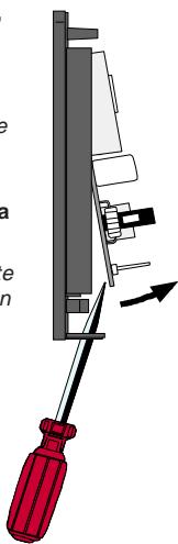
To remove the board, exert force only from the side indicated.

CAME DIR 10 - ASSEMBLY DESCRIPTION - 2

Connection examples to a CAME electric panel

CAME DIR 10 - Connection examples to a CAME electric panel - 1

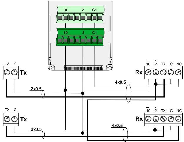
Connection for REOPENING DURING CLOSURE

CAME DIR 10 - Connection examples to a CAME electric panel - 2

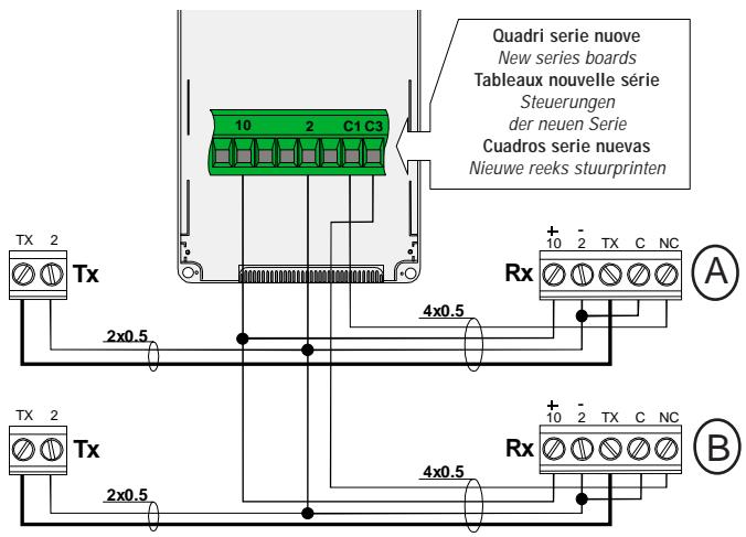
Connection of TWO COUPLES: (A) one for REOPENING DURING CLOSURE and (B) one FOR PARTIALLY CLOSED

CAME DIR 10 - Connection examples to a CAME electric panel - 3
Table of contents Click a title to access it
Manual assistant
Powered by Anthropic
Waiting for your message
Product information

Brand : CAME

Model : DIR 10

Category : Photoelectric cell