
MR8003 - Automatic door sensor CAME - Free user manual and instructions
Find the device manual for free MR8003 CAME in PDF.


| Brand | CAME |
| Model | MR8003 |
| Product Type | Automatic Door Sensor |
| Detection Method | Active Reflective Infrared |
| Max. Mounting Height | 3.0 m |
| Horizontal Detection Angle | ±7° adjustable in 3.5° steps |
| Vertical Detection Angle | ±4° adjustable in 1° steps |
| Power Supply | 12 to 30 V AC/DC |
| Power Consumption | 160 mA max. (at 12 V AC) |
| Output Type | Form C Relay (50 V, 0.3 A max.) |
| Relay Hold Time | 0.5 s |
| Response Time | Less than 0.3 s |
| Operating Temperature | -20 °C to +55 °C |
| Weight | 200 g |
| Housing Color | Silver |
| Included Accessories | Cable (3 m), mounting screws, template, adjustment tool, manual |
| Main Functions | Presence and motion detection, width/depth adjustment, snow mode, anti-interference |
| Maintenance and Cleaning | Clean the detection window with a damp cloth. Do not use solvent. |
| Safety | Do not disassemble, wash or repair yourself. Follow local regulations. |
| Operation Indicator | Green (standby), Red (1st line active), Orange (other lines active) |
Frequently Asked Questions - MR8003 CAME
User questions about MR8003 CAME
0 question about this device. Answer the ones you know or ask your own.
Ask a new question about this device
Download the instructions for your Automatic door sensor in PDF format for free! Find your manual MR8003 - CAME and take your electronic device back in hand. On this page are published all the documents necessary for the use of your device. MR8003 by CAME.
USER MANUAL MR8003 CAME
MANUFACTURER'S STATEMENT
Read this Operation Manual carefully before use, to ensure proper operation of this sensor.
Failure to read this Operation Manual may cause improper sensor operation and may result in serious injury or death.
This product is a non-contact activating switch intended for mounting on the header of an automatic door.
Do not use it for any other applications; otherwise proper operation and safety cannot be guaranteed.
Cautions:
- Follow the instructions (especially Note) in this Operation Manual when installing and adjusting the sensor.
- When setting the sensor's area pattern, make sure there is no traffic around the installation site.
- Before turning the power on, check the wiring to prevent damage or malfunction of equipment that is connected to the sensor.
- Do not wash, disassemble, rebuild or repair the sensor by yourself; otherwise it may cause electric shock or breakdown of the sensor.
- Only use the sensor as specified in the supplied instructions.
- Be sure to install the sensor in accordance with the local laws and standards of your country.
- Before leaving the jobsite, be sure that this sensor is operating properly and instruct the building owner/operator on proper operation of the door and this sensor.
SPECIFICATIONS
Model : MR8003
Cover color type : Silver
Mounting Height : 3.0m (9'10") Max.
Detection Area : See “Detection Area”
Detection Method : Active Infrared Reflection Method
Detection Angle : ±4° adjustable by 1° every one click Adjustments (Deep / Shallow)
Detection Width : ±7° adjustable by 3.5° every one click Adjustments (Right / Left)
Power Supply : 12 to 30V AC / DC
Current Draw : 160mA Max. (at 12V AC)
Operation Indicator: Green / Stand-by
Red / 1st Row Detection Active
Orange / Other Row Detection Active
Output : "Form C" relay 50V 0.3A Max.
(Resistance Load)
Relay Hold Time : 0.5 sec.
Response Time : < 0.3 sec.
Operating Temperature: -20°C to +55°C (-4°F to +131°F)
Weight : 200g (7.1oz)
Accessories : 1 Cable 3m (9'10")
2 Mounting Screws
1 Operation Manual
1 Mounting Template
1 Area Adjustment Tool
*The specifications herein are subject to change without prior notice due to improvements.
OUTER DIMENSIONS
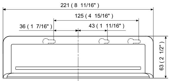
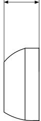
29.9 (1 3/16")

mm (inch)
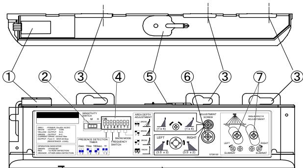
(8)
9
1:Connector
2: Sensitivity Switch
3: Mounting holes
4:Dipswitches
5:Area Adjustment Tool
6:Area Adjustment Screw
7:Width Adjustment Shutters
8:Operation Indicator
9: Detection Window
INSTALLATION
1
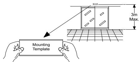
- Affix the Mounting Template to the mounting surface.
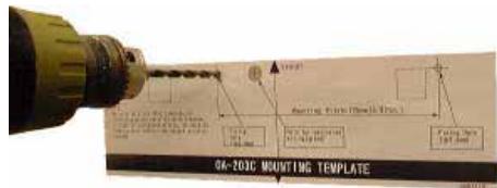
- Drill two mounting holes (Ø 3.4mm or 1/8").
- To carry through the wire to the header, drill a wiring hole (Ø 8mm or 5/16").
- After drilling the holes, remove the Mounting Template.
Note
Be sure that the mounting height is within the value of those in "SPECIFICATION."
2
The cable is arranged to connect to the door controller properly as shown below.
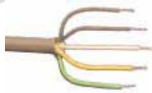
Grey
Grey

Power Supply
12 to 30V AC / DC
White
e:COM.
Yellow: N.O.
Green: N.C.
Note
Connect the cable when main power is turned off.
Note
When passing through the cable to the hole, make sure not to tear shield: otherwise it may cause electric shock or breakdown of sensor.
3
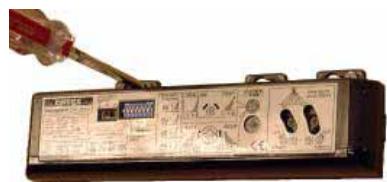
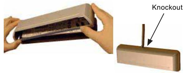
Remove the cover and attach the sensor with screws.
4
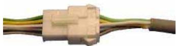
Plug the Connector for the sensor to that for the cable.
5
Supply power to the sensor. Adjust the detection area and set the various Switches. (See "ADJUSTMENT.")
Note
Make sure that you connect the cable correctly to the Control Unit of the door before turning the power on.
6
- Put back the cover on the sensor.
- If wiring is to be exposed, break the Knockout.
DETECTION AREA
Detection Areas are shown in the figure below.
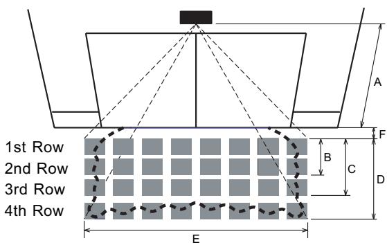

: Emitting Spot

Detection Area
| Provided Detection Row type | 1st | 2nd | 3rd | 4th |
| Presence Detection | ○ | ○ | × | × |
| Motion Detection | ○ | ○ | ○ | ○ |
After adjustment, turn the power off and on again, be sure to walk-test all of detection areas.
*The values of the chart blow is of the Emitting Spots, but not of the Detection Area.
The actual Detection Area may become smaller depending on the ambiance light and the colour / material of object and the floor as well as the entry speed of object.
[m]
| A | 2.00 | 2.20 | 2.50 | 2.70 | 3.00 |
| B | 0.28 | 0.31 | 0.35 | 0.38 | 0.41 |
| C | 0.68 | 0.75 | 0.85 | 0.92 | 1.02 |
| D | 1.18 | 1.30 | 1.48 | 1.59 | 1.77 |
| E | 2.10 | 2.30 | 2.60 | 2.80 | 3.10 |
| F | 0.16 | 0.18 | 0.20 | 0.22 | 0.25 |
[feet, inch]
| A | 6' 6 3/4" | 7' 2 5/8" | 8' 2 7/16" | 8' 10 5/16" | 9' 10 1/8" |
| B | 11" | 1' 3/16" | 1' 1 3/4" | 1' 2 15/16" | 1' 4 9/16" |
| C | 2' 2 3/4" | 2' 5 1/2" | 2' 9 9/16" | 3' 1/4" | 3' 4 3/16" |
| D | 3' 10 7/16" | 4' 3 3/16" | 4' 10 1/4" | 5' 2 5/8" | 5' 9 11/16" |
| E | 6' 10 11/16 | 7' 6 9/16" | 8' 6 3/8" | 9' 2 1/4" | 10' 2 1/16" |
| F | 6 5/16" | 7 1/16" | 7 7/8" | 8 11/16" | 9 13/16" |
ADJUSTMENT
1
Adjusting the Pattern Width
Setting the Width adjustment shutters
| Opens All Areas | Eliminate 1|2 | Eliminate 7|8 | Eliminate 1|2|7|8 |
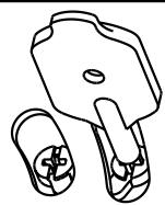
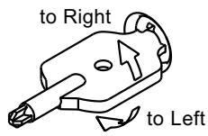
Adjusting the Width Angle Left or Right: between 0^ to 7^ (3.5^ per click)
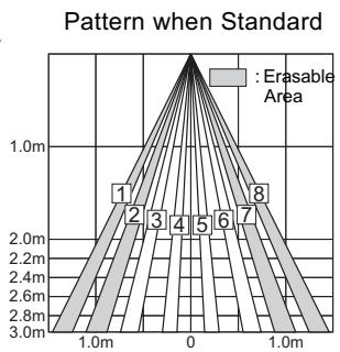
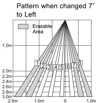
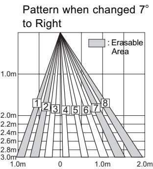

Setting the pattern for exact door opening may give a slow response to side approaching traffic.
2
Adjusting the Pattern Depth
Setting the Row with the Dipswitch 7 & 8.
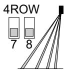
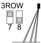
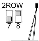
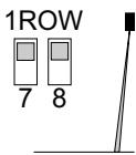
Adjusting the Depth Angle between -4^ to 4^ (1° per click).
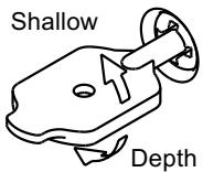
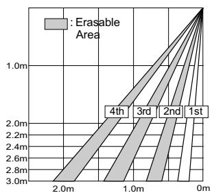
Pattern when Standard
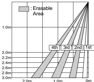
Pattern when changed -4^ to Shallow (inside).
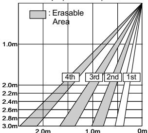
Pattern when changed 4^ to Deep (outside).

Set the pattern for actual traffic. It may cause slow activation for the traffic from the front, when the Row is eliminated.
3
Setting of Sensitivity Switch and Dipswitches
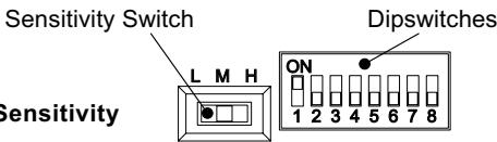
Setting the Sensitivity
Normally set to "M."
"H" increases the sensitivity and "L" lowers the sensitivity.
Setting the Presence timer
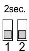
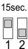
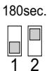
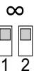
1st Row and 2nd Row from door provide the presence detection.
(1) Select the presence detection time.
(2) Turn the power off and on again. Otherwise it may leave door open for the duration of the presence time set.
(3) After making sure that the door closes, wait for 10 seconds before entering the detection area to set the Presence timer.
Setting the Frequency Function (Interference Prevention)
Four different frequencies can be set by adjusting the Dipswitch 3 and 4.
Position Position Position Position
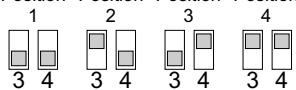

When two or more sensors are installed close to each other, it is possible that they interfere. When that happens, change the Frequency.
Setting the Snow mode
Set the Dipswitch5 and 6 to snow mode, if the sensor is used in a region with snow or a lot of insects.
normal
Immunity
snow mode
sr


heavy
snow
mode
6
CHECKING
Check the operation according to the chart below.
| Entry motion (image) | Power OFF | Outside the Detection area | Entry into 3rd or 4th Row | Entry into 2nd Row | Entry into 1st Row | Outside the Detection area |
| Sensor status | Power OFF | Stand-by | Motion Detection Active | Motion or Presence Detection Active | Stand-by | |
| Operation indicator | OFF | Green | Orange | Red | Green | |
| Output | ○—Yellow ○—Green ○—White | ○—Yellow ○—Green ○—White | ○—Yellow ○—Green ○—White | ○—Yellow ○—Green ○—White | ||

The door may open once after the power is switched on.
Inform the following items to the building owner/operator
- When turning the power on, always walk-test the sensor pattern to ensure proper operation.
- Always keep the detection window clean. If dirty, wipe the window with a damp cloth. (Do not use any cleaner or solvent.)
- Do not wash the sensor with water.
- Do not disassemble, rebuild or repair the sensor yourself; otherwise electric shock may occur.
- Contact your installer or the sales engineer if you want to change the settings.
- Do not place an object that moves or emits light in the detection area. (Ex. Plant, illumination, etc.)
- Do not paint the Detection Window.
TROUBLESHOOTING
| TROUBLE | POSSIBLE CAUSE | SOLUTION |
| NE DOES NOT OPERATE | Power supply is not adequate. | Adjust to stated voltage. |
| Connection Failure. | Check the wiring and the connector. | |
| DOSE NOT OPERATE CONSISTENTLY | Dirty detection window. | Wipe the detection window with a damp cloth. (Do not use any cleaner or solvent.) |
| Sensitivity is Low. | Set the Sensitivity Switch “H.” | |
| OPERATES BY ITSELF (GHOSTING) | There is an object that moves or emits light in the detection area. (Ex. plant, illumination, etc.) | Remove the object. |
| Vibration of the header. | Secure the header. Or set the Sensitivity Switch “L.” | |
| Sensitivity is high. | Set the Sensitivity Switch “L.” | |
| Waterdrops on detection window. | Install in a place keeping the waterdrops off. OR use a rain-cover (Optional). | |
| Detection area has interfered the area of another sensor. | Set the different frequency position each other. | |
| The detection 1st row spots are overlapping with the door / header. | Adjust the detection area to deep (outside). | |
| There is an reflected object in the detection area. Solar light reflects. | Remove the object. | |
| There was a puddle left by rain or snow. The floor has gotten wet. | This sensor is equipped with the anti-malfunction. However, pay attention when installing as malfunction may occur under the left conditions. | |
| The exhaust of the car and the fog penetrate into the detection area. | ||
| DOOR STAY OPEN OR CLOSED | Presence timer is Infinity. There was an abrupt condition change in the detection area. | Turn the power off and on again. |
| Contact your installer or the sales engineer if: - the trouble still persists after checking and remedying as described above. | ||
DECLARATION CE OF CONFORMITY
Pursuant to the Electromagnetic
compatibility Directive
Is fully liable in declaring that the
products listed below:
ACTIVE INFRARED PRESENCE
SENSORS
MR8003
comply with the National Law related
to the following European Directives
and to the applicable parts of the
following Standards:
89/336/EEC - 92/31/EEC
Electromagnetic compatibility Directive
89/106/EEC
Construction products Directive
··
EN 61000-6-2
EN 61000-6-3
EN 13241-1
Dosson di Casier, 29th November 2005
The Managing Director
Andrea Menuzzo
Reference code to
request a true copy
of the original
DDFEGB
R001 Ver 1.1

CAME
CANCELLI AUTOMATICI
ASSISTENZA TECHNICA
NUMERO VERDE
800295830
WEB
www.came.it
info@came.it
SISTEMA QUALITA
CERTIFICATO

CAME CANCELLI AUTOMATICI S.P.A.
DOSSON DI CASIER (TREVISO)
(+39)04224940 (+39)04224941
CAME NORD S.R.L. COLOGNO MONZESE (MI)
(+39)0226708293 (+39)0225490288
CAME SUD S.B.L. NAPOLI
(+39) 0817524455 (+39) 0817529109
CAME (AMERICA) L.L.C. MIAMI (FL)
(+1) 3055938798 (+1) 3055939823
CAME AUTOMATISMOS S.A MADRID
(+34) 0915285009 (+34) 0914685442
CAME BELGIUM LESSINES
(+32) 068 333014 (+32) 068 338019
CAME FRANCE S.A. NANTERRE CEDEX (PARIS)
)(+33)0146130505 (+33)0146130500
CAME GMBH KORNTAL BEI (STUTTGART)
(+49) 0715037830 (+49) 07150378383
CAME GMBH SEEFELD BEI (BERLIN)
(+49) 03 33988390 (+49) 03 339885508
CAME PL SP.ZQ.O WARSZAWA
(+48) 022 8365076 (+48) 022 8369920
CAME UNITED KINGDOM LTD NOTTINGHAM
(+44) 01159210430 (+44) 01159210431
- MANUFACTURER'S STATEMENT
- Cautions:
- SPECIFICATIONS
- OUTER DIMENSIONS
- INSTALLATION
- DETECTION AREA
- ADJUSTMENT
- 1
- Adjusting the Pattern Width
- 2
- Adjusting the Pattern Depth
- 3
- Setting of Sensitivity Switch and Dipswitches
- Setting the Sensitivity
- Setting the Presence timer
- Setting the Frequency Function (Interference Prevention)
- Setting the Snow mode
- CHECKING
- Inform the following items to the building owner/operator
- TROUBLESHOOTING
- DECLARATION CE OF CONFORMITY
- ACTIVE INFRARED PRESENCE
- SENSORS
- MR8003
- 89/336/EEC - 92/31/EEC
- 89/106/EEC
Brand : CAME
Model : MR8003
Category : Automatic door sensor