USER MANUAL C07867 DEVILLE
INSTALLATION AND OWNERS MANUAL
4.1 Surrounds
4.2 Optional accessory
- CONDITIONS FOR THE INSTALLATION OF THE APPLIANCE 18
5.1 Definition of components included in the smoke evacuation system
5.2 Characteristics and size of the smoke flue to which the appliance must be connected
5.2.1 Type of Smoke Flue
5.2.2 Minimum Flue Section
5.2.3 General Recommendations
5.3 Type and characteristics of the pipe connecting the appliance to the smoke flue
5.4 Draught requirements
5.5 Ventilation of the area in which the appliance is to be installed
5.6 Walls in the vicinity of the appliance, building-in dimensions and type of necessary insulations
5.6.1 Installation advice
5.6.2 Building-in and insulation for a 70 K maximum overheating of the chimney walls
5.7 Recommendations and typical installations
5.7.1 Installation within an existing fireplace made of refractory materials
5.7.2 Installation within an existing fireplace made of refractory materials
5.8 Preparation and installation of the appliance in the fireplace
- CONDITIONS FOR THE USE OF THE APPLIANCE 23
6.1 Lighting the insert for the first time
6.2 Fuel
6.2.1 Recommended Fuel
6.2.2 Prohibited fuels
6.3 Use of controls and accessories
6.4 Using the appliance
6.4.1 Lighting the insert
6.4.2 Working requirements
6.4.2.1 Working with doors closed
6.4.2.2 Ventilator
6.4.2.3 Ash Removal
6.4.2.4 Safety Rules
- SWEEPING AND MAINTENANCE RECOMMENDATIONS FOR THE APPLIANCE AND SMOKE FLUE 26
7.1 Removal of the deflector
7.2 Removal of the draught damper
- SERVICING & MAINTENANCE OF THE VENTILATOR 27
8.1 Removal of the ventilator support
8.2 Electric diagram
- GLOBAL TERMS OF WARRANTY 28
You are advised to read carefully and in full the information provided in order to get the best performance - and the most satisfaction - out of your DEVILLE insert.
Failure to comply with the assembly, installation and operating instructions places all responsibility upon the person(s) concerned.
THIS APPLIANCE MUST BE INSTALLED IN COMPLIANCE WITH CURRENT D.T.U. SPECIFICATIONS.
All local, national and European regulations must be respected when using this appliance. The appliance must not be modified.
INSTALLATION MUST BE MADE BY A QUALIFIED TRADESMAN.
1 - DEFINITION
This turbo insert complies with French Standard NF EN 13229.
This insert hearth is a continuous heating appliance with an on-grid combustion, using wood, with a semi-closed combustion chamber.
It is meant to be installed in a new fireplace to be built, or in an existing hearth.
Note the serial number written on the label sticked on the unit and on the warranty certificate. Write this number in the following case :
This serial number will be necessary to identify the unit in case of spare parts requirements.
Device in accordance with the Electromagnetic Accountancy Directive 89/336/EEC altered by the Directive 93/68/EEC.
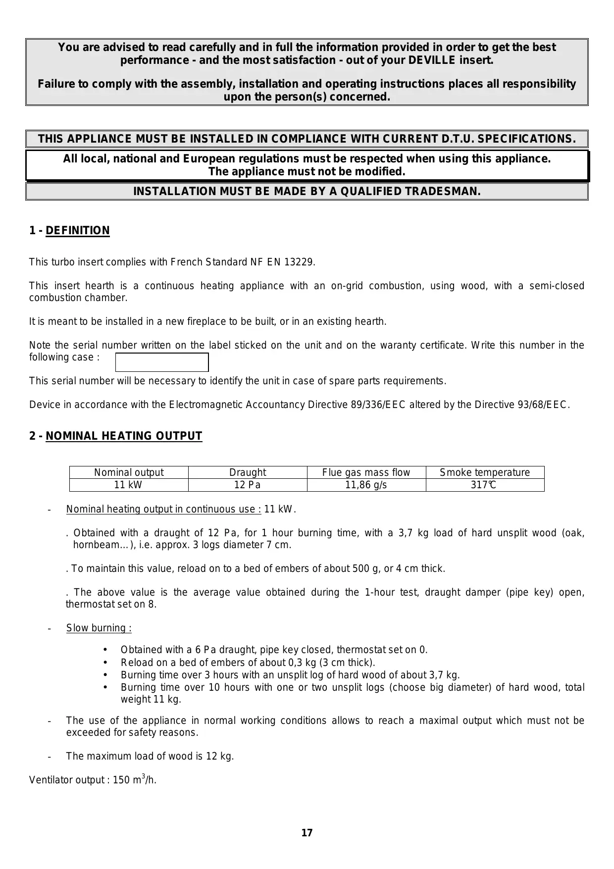
2 - NOMINAL HEATING OUTPUT
| Nominal output | Draught | Flue gas mass flow | Smoke temperature |
| 11 kW | 12 Pa | 11,86 g/s | 317℃ |
Nominal heating output in continuous use: 11 kW.
. Obtained with a draught of 12 Pa, for 1 hour burning time, with a 3,7 kg load of hard unsplit wood (oak, hornbeam...), i.e. approx. 3 logs diameter 7 cm.
. To maintain this value, reload on to a bed of embers of about 500 g, or 4 cm thick.
The above value is the average value obtained during the 1-hour test, draught damper (pipe key) open, thermostat set on 8.
-
Slow burning :
-
Obtained with a 6 Pa draught, pipe key closed, thermostat set on 0.
- Reload on a bed of embers of about 0,3kg (3 cm thick).
- Burning time over 3 hours with an unsplit log of hard wood of about 3,7kg .
-
Burning time over 10 hours with one or two unsplit logs (choose big diameter) of hard wood, total weight 11kg .
-
The use of the appliance in normal working conditions allows to reach a maximal output which must not be exceeded for safety reasons.
- The maximum load of wood is 12 kg .
Ventilator output : 150 m³/h.
3.1 DESCRIPTION
The main components of your insert are indicated below and identified on Fig. 1.
The Deville turbo-insert is made of 4mm steel, the inside is covered on the back and on both sides with cast iron decorated plates. The two cast iron doors, as well as the ash pan door, are fitted with seals which ensure tightness and allow the appliance to stay in for a very long time. The burning speed is adjusted with the thermostat.
A two-speed blower allows the circulation of hot air to be activated. The top of the casing includes 4 connections diam. 125. This equipment allows you to send a hot air flow in 4 different directions (adjacent rooms). If not connected with hot air ducts, your insert will provide a better convection in the room where it is installed.
The draught damper (pipe key) allows to reduce the excessive depressions of some flue pipes.
| C07836 | C07867 | C07887 |
| Net weight | 186 kg | 175 kg | 173 kg |
3.2 OVERALL DIMENSIONS (FIG. 2)
Outside dimensions (mm):
| Width | Height | Depth |
| Overall | 772 | 730 | 514 |
4 - SURROUNDSD AND OPTIONAL ACCESSORY
4.1 SURROUNDSD
Your turbo insert can be installed within either a Deville stone fireplace (choose among our commercial brochure) or an existing fireplace.
4.2 OPTIONAL ACCESSORY
On request, your insert can be completed with a barbecue kit C07012, for pleasant and cheerful grill-parties (Fig. 3).
5 - CONDITIONS FOR THE INSTALLATION OF THE APPLIANCE
IMPORTANT : TO AVOID ANY FIRE RISK, THIS APPLIANCE MUST BE INSTALLED IN COMPLIANCE WITH CURRENT RELEVANT SPECIFICATIONS (D.T.U. 24-2-2) AND IN THE RESPECT OF THE PRESENT INSTRUCTIONS. INSTALLATION MUST BE ACHIEVED BY A QUALIFIED TRADESMAN.
Installation should comply with the basic recommendations given below. However, these cannot under any circumstances replace strict application of any of the provisions of DTU 24-2-2.
5.1 DEFINITION OF COMPONENTS INCLUDED IN THE SMOKE EVACUATION SYSTEM (FIG. 4)
5.2 CHARACTERISTICS AND SIZE OF THE SMOKE FLUE, TO WHICH THE APPLIANCE MUST BE CONNECTED
5.2.1 Type of Smoke Flue
5.2.1.1 New Smoke Flue
- The following materials must be used :
. Fireclay flue blocks compliant with French Standard NF P 51-311
Concrete flue blocks compliant with NF P 51-321
. Composite metal pipes compliant with NF D 35-304 and NF D 35-303
. Fireclay bricks compliant with NF P 51-301
. Refractory bricks compliant with NF 51-302
- The use of certified insulating materials means that on-the-spot insulating work can be avoided, particularly where the chimney stack is concerned.
5.2.1.2 Existing Smoke Flue
The installer is responsible for existing parts. He should check the condition of the flue and carry out any work required in order to ensure that it is in proper working order and compliant with the regulations in force.
He should sweep the flue and then check the following points very thoroughly :
. Compatibility of the flue with the intended use
. Stability
. The flue must be empty and smoke-tight (DTU 24-1, Appendix II)
If the flue is not compatible, make a casing using an approved method (^*) or install a new flue.
(*) French assessment and certification system
5.2.2 Minimum Flue Section
| Possible working with doors open | Working with doors closed |
| Square or oblong flue blocks | Minimum section 4 dm2 | Minimum section 2,5 dm2 |
| Circular flues | Minimum diameter 200 mm | Minimum diameter 153 mm |
5.2.3 General recommendations
- A good flue will be built of materials with low heat conducting properties so that it stays hot.
It should be completely smoke-tight, stable and have no rough spots.
- There should be no sudden changes in section (slope in relation to the vertical less than 45^ ).
- It should extend at least 0.4 m above the ridge of the roof and of adjacent roofs.
- Two appliances should not be connected to the same flue.
It should come out into the room containing the appliance at a height of at least 50~mm , unless special case indicated by the flue's manufacturer.
- The interior face should be at least 16 cm away from any wood or combustible materials.
- Flue blocks should be placed with the male part towards the bottom so as to avoid any leaks to the outside.
- The flue should include no more than two changes of direction, i.e. no more than one non-vertical section. The bend angle should not exceed 45^ over a total flue height limited to 5m . For any greater height, this angle should not exceed 20^ .
- Smoke-tightness, insulation, openings in walls or floors and sale fire distances should all strictly comply with the provisions of DTU 24-2-2.
5.3 TYPE AND CHARACTERISTICS OF THE PIPE CONNECTING THE APPLIANCE TO THE SMOKE FLUE
- A connecting pipe must be installed between the appliance and the smoke flue outlet.
The pipe should consist of an "Avis Technique" approved rigid or flexible multi-fuel tube designed to be used directly with a closed fireplace.
It should be noted that the following are forbidden : aluminium, aluminium steel and galvanized steel.
- The flue must be visible over its whole length through a grille or inspection flap and be able to be swept by mechanical means. Any expansion should not adversely affect the smoke-tightness of the joins at either end or its mechanical performance or that of the smoke flue. Its design, and more especially the connection between it and the smoke flue, should be such as to prevent the accumulation of soot, particularly when it is being swept.
- Connections to the appliance and the flue should strictly comply with DTU 24.2.2 and with the specifications of the pipe's manufacturer; they should include all the recommended parts (end pieces and all other fittings).
5.4 DRAUGHT REQUIREMENTS
Draught is measured on the connecting pipe at a point approximately 50~cm above the outlet on the appliance.
The following draught is required for proper working with the doors closed :
. 6 Pa at reduced speed (0,6 mm WG)
. 12 Pa at normal speed (1,2 mm WG)
The installation of a damper is highly recommended (Fig. 5).
The damper ensures that the appliance works properly, even when the draught is considerable (high flue, piping). It should be readily visible and accessible.
The damper does not affect the insert performance when doors are open.
5.5 VENTILATION OF THE AREA IN WHICH THE APPLIANCE IS TO BE INSTALLED
- The appliance needs air in addition to the air required by the statutory air change rate. This is obligatory when the dwelling includes mechanical ventilation.
- The air intake should give directly to the outside or should be located in an area ventilated to the outside; it should also be protected by a grille (see recommendations on Fig. 6).
- The air outlet should be located directly either in the fireplace and come out near the thermostat adjusted air inlet, or as near as possible to the appliance. The user should be able to close it off when it comes out directly into the room.
The air intake section should be at least equal to one-quarter of the section of the smoke flue with a minimum of :
. 50~cm^2 for use with doors closed
. 200~cm^2 if people wish to use the insert with open doors
It may be necessary to stop the extractor of the mechanical ventilation so as to avoid smoke coming back into the room when the doors are open.
5.6 NATURE OF WALLS AND OTHER BOUNDARY STRUCTURES IN THE VICINITY OF THE APPLIANCE, BUILDING-IN DIMENSIONS AND TYPE OF PROTECTIONS/INSULATIONS TO USE
5.6.1 Installation advice
Remove all materials, that are either combustible or affected by temperature, from walls and inside elements (doors, walls and ceilings) near the chimney and the fireplace.
The appliance should be encased in MO-rated combustible materials.
The floor should be of incombustible material from under the appliance to at least 400mm in front of the appliance.
If the mantelpiece is made of a combustible material (wooden beam, for example), it must be protected by some sort of incombustible material, by a deflector or by the fascia (see DTU 24-2-2 and Fig. 10).
If the supporting wall is a light partition wall with combustible built-in insolation, it must be lined with incombustible material: 10 cm cellular concrete with a 2 cm cavity across the whole width of the fireplace extending 5 to 10 cm each side.
5.6.2 Building-in and protection to limit overheating of the casing walls to 65K
To limit overheating of the casing walls, the instructions below should be followed :
- Back wall, both sides and top must be insulated.
- The floor must be protected.
- Respect minimum thermal protections.
- Implement the convection air system of the appliance.
- Comply with the minimum fitting dimensions to limit overheating of the fireplace walls to 65K ( K = ^ above ambient temperature) and protect the appliance (Fig. 7).
The insulating material must be rigid and able to support high temperatures without getting warped or damaged (rated MO material), such as rockwool, 30~mm thick, covered with aluminium foil exposed to the heat from the appliance.
The global conductivity of the insulating material must be inferior to 1,3W / m^2C
Example: 30 ~mm rockwool, conductivity inferior to 0.04 ~W / 3^ C , or 80 ~mm insulating brick, conductivity inferior to 0.1 ~W / m^ C .
Air convection around the stove.
Do not obturate the ventilation points : air coming in from the front under the appliance, circulating between the side and rear double walls.
The floor shield consists in a reflective metal shielding (thick 7/10^e ).
NOTE : If the appliance is installed within an existing fireplace made of refractory materials, basically designed for an open fire, the minimum building-in dimensions should be complied with in order to protect the appliance.
NOTA: On completion of work, the surface temperature of the backing walls should not exceed 50^ in areas where they are accessible (Fig. 8).
5.7 RECOMMENDATIONS AND TYPICAL INSTALLATIONS
The appliance must be set up on a floor with a sufficient bearing capacity. If the existing construction does not comply with this prior requirement, appropriate measures must be taken to allow the floor to bear the appliance, such as setting up a load distribution plate.
5.7.1 Installation within a new fireplace to be built
- Figures 26, 27, 28 and 29, given as examples, show installation in a DEVILLE fireplace. They show different connection methods, which are :
Fig. 26: connection into masonry flue already installed in ceiling by means of special component
Fig. 27: connection into masonry flue already installed in ceiling by masonry flange
Fig. 28: connection into masonry flue from the floor with refractory concrete lining and sand filling
Fig. 29: connection into masonry flue from the floor and accessible soot hatch
- A hot air outlet with a minimum cross-section of 400~cm^2 should be installed at the front or sides, at 300~mm from the ceiling, to reduce the inside temperature of the structure.
5.7.2 Installation in an existing fireplace built with refractory materials and normally intended for an open fire
Connection to the fireplace (see example Fig. 10):
- It is essential to ensure that the base of the smoke flue ① is completely smoke-tight. Any air coming in will prevent the appliance from working properly.
- Put the required sealant all around the steel flange ④ . In order to do this :
Fix the flange with refractory mortar.
The top part of the mortar will result in the shape of a funnel.
The end of the pipe should not extend beyond the flange ④ after insertion into the outlet on the appliance.
The diameter of the connecting pipe must be at least 180mm
- Place the connecting pipe ② in the sealed flange ④ and fix it in the high position.
Connection to the appliance :
- Position the appliance in the fireplace (see § 5.8) and fit the pipe into the outlet of the appliance (Fig. 9).
NOTA : The connecting pipe ② and the flange ④ should be in stainless steel, minimum thickness 0,4 mm.
If there is not enough place over the appliance, several solutions can be used to fit the pipe.
Pre-insert in the pipe, about 10cm from the bottom, a pin by which the pipe can be held, with your hand inside the appliance. The pin can stay where it is without any effect on performance (Fig. 9).
It is also possible, once all parts taken out from the inside of the unit, to remove the connecting nozzle (6 screws HM6). The pipe can then be introduced through the inside of the appliance.
The ventilation of the hood will be realized as for a new fireplace (refer to § 5.7.1).
5.8 PREPARATION AND FITTING OF THE APPLIANCE WITHIN THE FIREPLACE
5.8.1 General recommendations
To reduce the weight of the appliance, and make its installation easier, remove the deflector, the other cast iron parts placed inside the unit, and also the doors (also remove the polystyrene wedge holding the deflector).
5.8.2 Use of the lateral squares
They make the embedding of the appliance within the fireplace easier.
Before casing the insert, screw on the sides of the unit the 4 screws supplied (there are 2 holes on each side). Stop the screwing in order to be able to fit easily, without too much play, the side squares on the screws after having put the appliance in its place.
Once the appliance is installed, slide the 2 squares, cut-out parts facing screws, then take squares down up to floor (refer to Fig. 11 and 12).
5.8.3 Fitting of the upper hot air grille
Remove the draught damper from the top (Fig. 22); draw out the control stem, flap, crossbar, spring and stem ring.
Introduce the control stem through the hot air grille (between 2^nd and 3^rd bar from the top of the grille), then reassemble successively the ring, spring and crossbar.
Adjust the whole on the appliance and fix the grille with 2 of the screws supplied in the bag (use the 2 holes placed at the bottom of the grille).
Refit the flap, tighten its fixing screw (vertical key for vertical flap).
5.8.4 Hot air supply
Hot air can be supplied in the adjacent rooms :
- Remove the 4 pre-cut obturators on the top of the appliance : drill (using a 6 bit) through the 3 existing holes ( 2). Put the 125 hot air outlets ① supplied with the appliance in place of the obturators (Fig. 13).
- Slightly unscrew the 2 fixing screws of the hot air grille ; then slide the obturating plate ② between the grille and the unit itself. Use the 2 remaining screws from the bag to fix the plate on the appliance (Fig. 13). Then tighten the 2 fixing screws of the hot air grille.
- Ensure a thermal protection of the hot air flues (minimum 16 cm between hot air duct and combustible materials), and use insulated ducts. The selected materials should be highly heatproof (classification MO).
WARNING : The hot air ducts should not be in contact with any parts of the smoke evacuation circuit. Even more important, the hot air ducts should in no case run through the smoke pipe.
-
Go from the appliance with vertical ducts as high as possible in order to privilege circulation by convection, limit the lengths of horizontal ducts and the number of bends.
-
Make sure that air comes back from the adjacent rooms to the room where the insert is installed ("return" circuit). Also check that the hot air function does not affect the home ventilation system.
It is important to make sure, while insert working, that the convection air comes in through the intake ports and comes out through all the outlet vents. If it is not the case, reduce the section of the outlet which works properly until the other outlets blow hot air : the use of adjustable nozzles makes this balancing easier.
The obturating plate, fitted over the front air outlet, can be adjusted in order to regulate the hot air flow of the different outlets; however, this plate maintains a 10 mm "safety" air flow: this prevents overheating of the appliance when none of the 4 nozzles Ø 125 is open.
5.8.5 Blower electrical connection
- The appliance is delivered with a flexible cable of an approximate length of 1.5 ~m , allowing it to be connected to the electricity supply network. The end of the cable is situated at the bottom of the left-hand rear part of your insert and you will have to pull it (without forcing) to take it out. On the fixed installation, set up an omnipolar partition device with an opening distance of contacts of at least 3 ~mm : this device will enable you to isolate the appliance from the electrical supply network. The installation should be in accordance with the French standard NFC 15100, and in particular the earth (green and yellow wire) should be connected.
- The rated power of the blower is 40W - incoming voltage 230V .
It might be necessary to remove the ventilator or the fireplace : for this purpose keep a sufficient length of cable so that these operations may be carried out without pulling on the cable.
5.8.6 Final fitting of the turbo insert
Once your turbo insert is in its right position, replace all cast iron parts previously removed, successively the deflector, plates, combustion grate and door.
5.8.7 Adjusting of the thermostat
Adjusting is factory-set. However we recommend checking it before first lighting. For this operation, open ashpan door and remove ashpan.
For a 20^ room temperature, when the control lever is set on 0, the gap between the supporting plate and the flap must be zero (cold appliance) (Fig. 14).
However the flap must be subjected to no thrust, it must lift from its supporting plate when the knob is set to position 1.
If required, change the flap adjustment by acting upon the adjustment knob : access inside the ashpan compartment.
NOTA: With use, it may become difficult to turn the thermostat knob ①. In that case, oil the control screw ② (graphite grease, motor oil) (refer to arrows on Fig. 15).
6 - USE OF YOUR DEVILLE INSERT
Your "closed hearth" is an extremely efficient heating appliance :
High output, slow burning, adjustable output by thermostatic regulation.
6.1 FIRST LIGHTING
- When the fireplace is completed and the appliance in place, give the various building materials time to dry: connection and seals on the smoke pipe, stones, hood, etc... Generally count 2 to 3 weeks for drying.
- After lighting the insert for the first time (see § 6.4.1), build a moderate fire for the first few hours using just one log with a diameter of about 15 cm ,with the thermostat set on position 4 : this will ensure that the temperature of all the parts of the fireplace increases gradually and that the appliance will expand normally.
- You may find that initially the insert gives off a smell of paint, in which case simply air the room.
6.2 - FUEL
6.2.1 - Recommended Fuel
Hardwood: oak, honbeam, beech, Chesnut, etc.
It is advisable to use only well-seasoned wood with a maximum moisture content of 20% , i.e. 2 years dry storage following cutting, in order to obtain better efficiency and avoid sooting smoke pipe and glasses.
Do not use resinous woods (pine, fir, spruce, etc.), which involve more frequent maintenance of the insert and flue.
For a constant burning, load as described in § 2 – Nominal heating output.
For an intermediate burning, reduce the load.
For a long-lasting fire at low speed, use one or two unsplit logs (diameter superior to 15cm ).
6.2.2 - Prohibited fuels
All types of fuel other than wood are forbidden, in particular coal and its by-products.
Do not burn household refuse, plastics or by-products, greasy materials, waste made of manufactured wood, agglomerated products, painted or varnished woods ; all these are sources of pollution and risks of sooting.
The appliance should not be used as a waste incinerator.
Flare-ups from small pieces of wood, vine shoots or similar, bits of plank, straw and cardboard are dangerous and must not be used.
6.3 - USE OF CONTROLS AND ACCESSORIES
- Thermostat knob : may be hot, so must be handled with the poker. Set on position 0 to 8 according to required speed.
Example :
Position 8: normal burning
Position 3 et 5 : intermediate burning
Position 0 : slow burning
- Door handle : vertical rotation using the poker. Down : closed ; up : open (Fig.16).
- Poker : required for moving logs inside the insert according to the combustion, also needed to operate the thermostat knob, the door handle, and to close the ashpan door.
- Scaper: for ash removal.
6.4 - USING THE APPLIANCE
6.4.1 - Lighting
- Set thermostat knob on position 8.
- Screw up some paper and place it on the grate along with some very dry kindling, then some bigger split wood on top (diameter about 3 to 5 centimetres).
Light the paper and close the doors (or leave them slightly ajar so that the fire catches more quickly).
- When the kindling is alight, open the doors and put in the wood recommended above.
6.4.2 - Operation requirements
6.4.2.1 - Operation in closed hearth mode
- The burning rate is adjusted by choosing a suitable load according to your needs and acting on the thermostat (refer to § 6.2.1. and 6.3).
Only re-load when all the flames have died down to leave a bed of embers. In particular, if you require a long staying time at slow burning rate, load into a bed of embers that are barely glowing. The return of fire will be slow but more certain than in an open hearth.
On the other hand, if you require fast burning, revive the fire with fire-lighters before loading.
- Continuous fire at slow burning rate, especially during mild periods and with moist wood, results in incomplete combustion which increases soot and tar deposits. Spells of slow burning should be alternated with periods at normal.
- After operation at slow burning rate, the glass may be darkened by a slight sooty deposit. This deposit normally disappears during faster burning owing to pyrolysis.
To avoid any blasts of smoke or even ashes when reloading, the following precautions must be taken when opening the doors :
- Open the draught damper (pipe key) in order to get a maximum smoke flow.
- Switch off the fan to avoid drawing in ash which may then fall from the front of the appliance.
- Open the doors slightly, wait a few moments for the draught to be established in open doors mode, and then slowly open the doors.
- After your have closed the doors, remove the ashes that may have fallen in front of the appliance, to prevent them from being drawn by the ventilator.
The user should follow these precautions in order to avoid dirt to the hot air outlets.
IMPORTANT :
For a good working of the whole, and to avoid the thermostat being damaged, it is absolutely required to keep the ashpan door closed when the appliance is being used. The door is rightly closed when the 2 bolts
are in the following position (Fig. 17).
6.4.2.2 - Ventilator
Select a speed of ventilation :
- Low speed, selector 8 in position I
High speed, selector 8 in position II
Set the appliance heating (see Instructions).
Select automatic operation (AUTO) or manual operation (MANU) with selector 14.
- In the MANU position : the fan is switched on and off by manual control. In this position, the blower function can be started up immediately and must be switched off by hand.
- In the AUTO position : the fan is operated automatically, when the whole of the appliance is warm, generally during the hour following the lighting. Its running is interrupted when the appliance is cold, generally at the fireplace's extinction.
If you want the blower to be started up immediately and then switched off automatically, select the MANU position when lighting and then switch to the AUTO position once the appliance is hot. The blower will then be switched off automatically.
6.4.2.3 - Ash Removal
The air used for burning the wood comes in under the grate when the thermostat flap is open. The incoming air also cools the grate. So in order to ensure the best performance from your insert and prevent damage to the grate through overheating, it is essential to empty out the ash so as to keep the grate clean : the ash level should never be so high as to reach the cast iron grate.
. Use the poker to open the ashpan door (introduce the end part of the poker into the hole of the ashpan door handle, and operate the poker as on Fig. 17).
. Use the scraper to remove ash from the grate.
The ashpan, located underneath the grate, is easily removed using its handle.
6.4.2.4 Safety Rules
- Never try to extinguish the fire with water.
- Be careful of the glass, which gets very hot. Keep children away from it.
- The insert gives out a lot of heat through the glass, so keep materials and heat-sensitive objects at least 1.50 metres away from it.
- Empty the ashpan into a special metal or otherwise inflammable receptacle used only for this purpose. Ashes that might appear cold can still be very hot, even if you think they have had enough time to get cold.
- Do not put easily flammable materials near the appliance.
- In case of chimney fire, put the thermostat on position 0 and close the draught damper (pipe key).
7- SWEEPING AND MAINTENANCE RECOMMENDATIONS : INSERT AND SMOKE FLUE
Mechanical sweeping of the smoke flue is obligatory. This should be done several times a year and at least once during the heating period. The contractor concerned should provide the necessary certificates.
For sweeping :
- Remove the deflector and the draught damper (pipe key) and put them back into place after sweeping (see instructions hereafter).
- Carefully check the condition of the appliance, and more especially smoketightness : seals, fixings, door and frame.
- Check the condition of the smoke flue and the connecting pipe ; all fittings should be in good mechanical condition and smoke-tight.
Using the vacuum cleaner, clean the inside of the hood to get rid of any dust and if necessary clear the hot air convection system (air inlet and outlet through the hot air supplying ducts) and fresh air inlet.
In case of problems, have your appliance or installation checked and repaired by a tradesman.
Clean the glasses with a damp cloth and ash ; if necessary, use a household cleaning product (soda products) following the user instructions. Wait until the appliance is completely cold before cleaning.
7.1 - REMOVAL OF THE DEFLECTOR
The deflector (Fig. 18) with notches (E) at the front (F) sides leans :
To replace the deflector
- follow the same steps in reverse.
7.2 - REMOVAL OF THE DRAUGHT DAMPER
Once the deflector removed, loosen the screw (A) (use box spanner H 10); release the knob and the control stem partially, without drawing them out of the grille, in order to release the flap (Fig. 22).
Nota : Set the knob in vertical position to make it easier for the pin to go through the grille.
To replace the draught damper
Follow the same steps in reverse. See to the right orientation of the key (vertical key for vertical flap).
8- SERVICING - MAINTENANCE OF THE VENTILATOR
8.1 REMOVAL OF THE VENTILATOR SUPPORT
- Remove the 3 fixing screws ① of the ventilator support and protection grid (Fig. 23).
- Remove the 2 screws and 2 fan rings (Fig. 23).
- Lift the grid to remove it.
- Draw the ventilator slantwise (Fig. 24).
1. TERMS AND CONDITIONS
Apart from the legal warranty, particularly for latent defects, Deville guarantees to deliver the furniture in case of obvious defects or non-conformity to the ordered furniture.
Without prejudice to the provisions that are to be taken concerning the carrier, claims on delivery of furniture concerning the obvious defects or the non conformity, must be issued by the Buyer in writing a registered letter with confirmation of receipt to Deville company with in 5 days after noticing the defect. It is up to the Buyer to prove the reality of the noticed defects and irregularities. The Buyer must let Deville every opportunity of noticing any of those defects and irregularities in order to salve then.
The Buyer must also keep the non standard supplies at the disposal of Deville, according to the instructions of the latter. All return of material, for any reasons, should be subject to a formal pre - agreement from Deville.
2. EXTEND
The warranty of Deville covers, except for any compensation or for damages, the free replacement or repairing of supplier the part acknowledged as being defected (except for wear and tear parts) by its services to the exclusion of the fees for the workplace, for the removal and for the shipping.
On enamelled equipments, appliances, crackles are never considered as a manufacturing defect. They are due to the difference of expansion of iron enamel or cast-iron enamel and don't alter the adherence.
Paid replacement parts are warranted for a six-month period from the invoicing date, any additional warranty agreed by a retailer from Deville doesn't commit Deville. Whenever claiming under a warranty, the guarantee with the stamp from the retailer Deville is strictly required. The above guarantee must be produced for any demand to repair the appliance under warranty, or a detachable slip or coupon of any such guarantee must, according to the own organisation of Deville, be returned to the latter within the required time. For lack of this, the date on the invoice issued by Deville can't be taken into account. The interventions under warranty can't have the effect of continuing the warranty.
3. WARRANTY PERIOD
The period of the agreed warranty ensured by Deville is for 2 years (5 years for the fireplace heating body) from the date when the appliance was purchased by the user, subject to the fact the claims -forecast by the above conditions-were done within the time allowed. The repairing, the replacement or the alteration of parts under the warranty period can neither have the effect of continuing the period of the latter, not get to any compensation for any fees, for late delivery, accidents or any such damages.
4. EXCLUSION
The warranty is unavailable for the following cases, without this list being exhaustive :
-
Fitting out, fitting out and assembling of appliances not due to Deville.
-
Consequently Deville can't be considered as responsible for damages or supplies, or accidents to persons due to local laws and regulations (for example the fact that there is no linking to the a earth ground connection, or a wrong drought of a fitting out).
Fair wear and tear of the supplies or abnormal use of the supplies including the case of industrial or trading use or a use of the supplies in different conditions from the ones it was built for. It is, for example, of non respect of the conditions described in the directions issued by Deville : display to outside conditions damaging the appliance ; such as excessive dampness or abnormal change of the electrical tension. Malfunction, damage or accident due to a shock, a drop, a carelessness, a failure of supervision or of service from the Buyer.
Any alteration, change or intervention made by a member of the staff or a company that is not approved by Deville, or manufactured with replacement parts that are not genuine or not approved by the manufacturer.
5. SPECIAL TERMS OF WARRANTY
These terms add and define the above general terms of warranty and come first to the former, refer to the enclosed leaf untitled : "special terms of sales Deville - warranty".
INHALT
Pages
- ALLGEMEINE GARANTIEBEDINGUGEN 41
9 - ALLGEMEINE GARANTIEBEDINGUGEN
1. MODALITÄTEN
6.1 PRIMA ACCENSIONE
The descriptions and features described here are given for information only and constitute no liability. In addition, and in line with our policy of quality enhancement, we reserve the right to modify or improve any of our products without notice.
***