
C07335 - 01-06 - Fireplace DEVILLE - Free user manual and instructions
Find the device manual for free C07335 - 01-06 DEVILLE in PDF.
User questions about C07335 - 01-06 DEVILLE
0 question about this device. Answer the ones you know or ask your own.
Ask a new question about this device
Download the instructions for your Fireplace in PDF format for free! Find your manual C07335 - 01-06 - DEVILLE and take your electronic device back in hand. On this page are published all the documents necessary for the use of your device. C07335 - 01-06 by DEVILLE.
USER MANUAL C07335 - 01-06 DEVILLE
INSTALLATION AND OWNERS MANUAL
1-FOREWORD 14
2-FIREPLACE CHARACTERISTICS 14
2.1 - Description
2.2 - Nominal heat output and reduced burn rate autonomy
2.3 - Description
2.4 - Dimensions
2.5 - Environment
3 - FIREPLACE INSTALLATION LOCATION CHARACTERISTICS 15
3.1 - Designation of the various parts of the smoke removal system
3.2 - Type and dimensional characteristics of the chimney flue to which the fireplace must beconnected.
3.2.1 - Chimney flue type
3.2.2 - Minimum flue cross-section
3.2.3 - A few general recommendations
3.3 - Type and characteristics of the connecting tube between the fireplace and the flue
3.4 - Draft conditions
3.5 - Ventilation of the room where the fireplace is installed
3.6 - Blower electrical connection
3.7 - Walls in the vicinity of the appliance
4 - INSTALLATION OF THE "READY TO INSTALL" FIREPLACE 17
5-FIREPLACE OPERATION 17
5.1 - Commissioning
5.2 - Combustible
5.2.1 - Recommended combustible
5.2.2 - Forbidden combustibles
5.3 - Operation of control devices and accessories
5.4 - Operation
5.4.1 - Lighting a fire
5.4.2 - Operation
6 - MAINTENANCE AND SWEEPING INSTRUCTIONS 20
6.1 - Maintenance and sweeping of the chimney flue
6.2 - Routine maintenance
6.2.1 - Adjusting the door closing mechanism
7 - GLOBAL TERMS OF WARRANTY 22
CAUTION : TO PREVENT THE RISK OF FIRE, THIS FIREPLACE MUST BE INSTALLED IN ACCORDANCE WITH ACCEPTED TRADE PRACTICES AND IN COMPLIANCE WITH THE TECHNICAL REGULATIONS STIPULATED IN THIS MANUAL.
THE INSTALLATION OF THIS APPLIANCE MUST COMPLY WITH CURRENT D.T.U. (French Code of Practice) SPECIFICATIONS.
INSTALLATION BY A QUALIFIED TRADESMAN IS RECOMMENDED.
We strongly recommend that you take the time to thoroughly read and familiarize yourself with this manual in order to obtain maximum enjoyment and satisfaction from your DEVILLE fireplace.
All local, national, and european regulations must be respected when using this appliance.
The nonobservance of the assembly, installation and operating instructions shall engage the liability of the individual(s) concerned. The unit must not be modified.
1-FOREWORD
-
The "ready to install" fireplaces, models are to be installed in the same manner as a wood burning stove. The rules for installation are identical, particularly as regards the following points:
-
The type and installation requirements of the chimney flue compatible with this usage.
- The connection of the fireplace to the chimney flue.
-
Room ventilation.
-
Chapter 4 specifically concerns the "ready to install" fireplace :
Installation against a backing wall.
- Height adjustment.
- Important, the "Ready-to-Install" fireplaces do not allow the connection of hot air outlet ducts: the safety of the environment can no longer be ensured if the screens which protect the backing wall are modified (pierced, moved).
- The following chapters provide basic recommendations for proper fireplace operation. The building technical rules DTU 24-2-2 and 24.1 fully describe the specifications related to smoke evacuation and fresh air intake requirements.
- The ready-to-install fireplaces C07335 and C07342 comply with the French standards NF EN 13240.
2 - FIREPLACE CHARACTERISTICS
2.1 - Description
The "ready to install" fireplaces, models are exclusively wood-burning, grate-type continuous combustion, semi-open heating appliances, and are designed to be installed against a backing wall without any additional protection.
2.2 - Nominal heat output and reduced burn rate autonomy
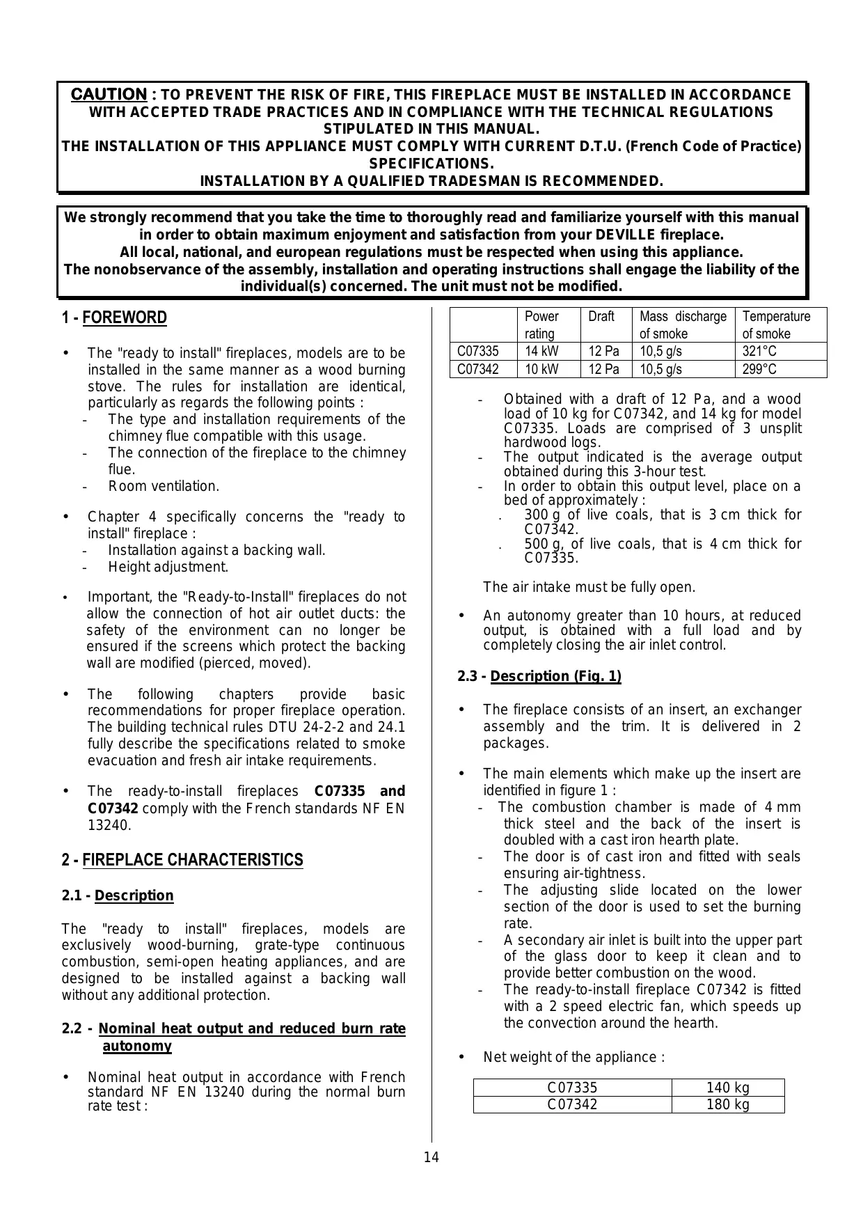
Nominal heat output in accordance with French standard NF EN 13240 during the normal burn rate test:
| Power rating | Draft | Mass discharge of smoke | Temperature of smoke | |
| C07335 | 14 kW | 12 Pa | 10,5 g/s | 321°C |
| C07342 | 10 kW | 12 Pa | 10,5 g/s | 299°C |
- Obtained with a draft of 12 Pa, and a wood load of 10 kg for C07342, and 14 kg for model C07335. Loads are comprised of 3 unsplit hardwood logs.
The output indicated is the average output obtained during this 3-hour test.
In order to obtain this output level, place on a bed of approximately :
300 g of live coals, that is 3 cm thick for C07342.
500 g, of live coals, that is 4 cm thick for C07335.
The air intake must be fully open.
- An autonomy greater than 10 hours, at reduced output, is obtained with a full load and by completely closing the air inlet control.
2.3 - Description (Fig. 1)
- The fireplace consists of an insert, an exchanger assembly and the trim. It is delivered in 2 packages.
-
The main elements which make up the insert are identified in figure 1 :
-
The combustion chamber is made of 4mm thick steel and the back of the insert is doubled with a cast iron hearth plate.
- The door is of cast iron and fitted with seals ensuring air-tightness.
- The adjusting slide located on the lower section of the door is used to set the burning rate.
- A secondary air inlet is built into the upper part of the glass door to keep it clean and to provide better combustion on the wood.
- The ready-to-install fireplace C07342 is fitted with a 2 speed electric fan, which speeds up the convection around the hearth.
Net weight of the appliance :
| C07335 | 140 kg |
| C07342 | 180 kg |
For handling of the appliance, remove the door or doors and the various cast iron parts located in the fireplace.
2.4 - Dimensions (Fig. 2)
2.5 - Environment (Fig. 2)
- The fireplace must be installed against a wall. The adjustable tube cover enables the height of the fireplace to be adjusted to that of the ceiling.
- The shields supplied with the fireplace provide heat radiation protection and hide the air cooling systems designed to protect the walls. It is imperative that all shields be installed in strict compliance with the indications below.
- The fireplace must be connected to the chimney flue by means of a 180 mm connecting tube for models C07335 and 153 mm connecting tube for models C07342 (see paragraph 3.3).
3 - FIREPLACE INSTALLATION LOCATION CHARACTERISTICS
3.1 - Designation of the various parts of the smoke exhaust system (Fig. 3)
3.2 - Type and dimensional characteristics of the chimney flue to which the fireplace must be connected
3.2.1 - Chimney flue type
3.2.1.1 - In the case of a new flue
The following materials may be used :
Terracotta chimney blocks in compliance with NF standard P 51-311.
Concrete chimney blocks in compliance with NF standard P 51-321.
- Composite metal chimney flues in compliance with NF standards D 35-304 and D 35-303 or which have been awarded a favorable "Technical Report" for this purpose.
Terracotta bricks in compliance with NF standard P 51-301.
- Fire bricks in compliance with NF standard P 51-302.
- The use of pre-insulated materials avoid having to install insulation at the job site, particularly for walls at the attic level and over the height of the stack (minimum thermal resistance: 0.43m^2kW ).
3.2.1.2 - In the case of an existing flue
-
The installer shall bear the responsibility for all existing sections. The condition of the flue must be checked and the necessary modifications made to ensure proper operation and compliance with regulations.
-
Sweep the flue, then perform a thorough examination in order to verify the following points:
-
Compatibility of the flue with its usage.
- Stability.
-
Vacuousness and tightness (Appendix II of DTU 24-1).
-
If the flue is incompatible, insert chimney stack tubing in accordance with a certified procedure, or install a new chimney flue.
3.2.2 - Minimum flue cross-section
| Regulations | Operation with doors closed |
| Square or rectangular chimney blocks | Minimum cross-section 2.5 dm2 |
| Round chimney flues | Minimum diameter 153 mm |
In all cases, the cross-section of the flue must be at least equal to that of the connection nozzle on the appliance.
3.2.3 - A few general recommendations
- In order to remain hot, a good flue should be made from materials which are poor conductors of heat.
-
The trim surrounding the flue should limit the outside superficial temperature to :
-
50^ C , in inhabited zones.
-
80^ C , in uninhabited or inaccessible zones.
-
The flue must be perfectly tight, stable and without internal surface roughness.
- The flue must not present sudden section variations (slope off vertical less than 45^ ).
- The flue opening must extend at least 0.4m above the ridge of the roof and neighboring roofs (Fig. 3).
- Two fireplaces must not be connected to the same flue.
- The flue must enter the room where the fireplace is to be installed by at least 50~mm .
- Its inside face must be at least 16cm from all wood and combustible material (Fig. 3).
- The flue must not have more than two offsets, that is to say not more than one non-vertical section.
- Masonry flue:
The angle of the offsets must not exceed 45^ for a total flue height under 5m . For flue heights greater than 5m , the offset angle must not exceed 20^ .
Insulated metal flue :
The angle of the offsets must not exceed 45^ with a height limitation of 5m between the top and bottom of the offset. The total flue height is not limited.
- Chimney blocks must be installed with the male portion facing downward so as to prevent runs from passing to the exterior.
- All seals, insulation, floor and ceiling feedthroughs, and firebreak distances must be performed in strict compliance with DTU 24-2-2.
3.3 - Type and characteristics of the connecting tube between the fireplace and the flue
- A connecting pipe must be installed between the appliance and the smoke flue outlet. This flue must be made with either rigid or flexible dual-fuel tubing, bearing a favorable "Technical Report" for direct connection to the closed insert.
It should be noted that it is strictly forbidden to use aluminum, aluminized steel and galvanized steel chimney flues.
The following are approved : black plate (min. thickness 2 mm), enamelled plate (min. thickness 0,6 mm) and stainless steel (min. thickness 0,4 mm). - This flue must be visible over its entire distance and be able to be mechanically swept. Fluedilation must not jeopardize upstream and downstream junction seals nor its mechanical characteristics or that of the chimney flue. Its design and particularly the connection with the chimney flue must prevent the accumulation of soot, especially during sweeping operations.
- The junctions with fireplace and the chimney flue must be performed in strict compliance with DTU 24.2.2 and the tube manufacturer specifications, using all recommended components (fittings, connections, etc.).
- The connecting tube cross-section must be at least equal to that of the smoke channel on the fireplace.
- If the connector is to be horizontal, there should be an ascending slope of 5cm per metre.
IMPORTANT:
The area located within a radius of 200mm around the connecting tube must be made of incombustible materials (concrete, bricks).
However, the use of combustible or incombustible materials which degrade above 90^ is authorized provided that the surfaces subjected to direct heat radiation from the connecting tube are heat insulated. The insulation used must bear an M0 fire rating (rock wool, ceramic fibers...) (Fig. 4).
3.4 - Draft conditions
-
The draft is measured on the connecting tube at approximately 50~cm after the fireplace's smoke channel.
Required draft for proper operation (door closed): -
6 Pa at reduced burn rate (0.6 mm WC).
-
12 Pa at normal burn rate (1.2 mm WC).
-
The installation of a draft damper is recommended. It can be installed:
Either on the connecting tube, in the tube cover, above the tube cover shield, in the case of an outlet at the top.
Or on the chimney flue, in the case of an outlet at the rear.
- The damper ensures that the appliance works properly, even when the draught is considerable (high flue, piping). The damper should be visible and readily accessible and installed in the same room as the stove.
- The damper does not affect stove performance when the door is open.
3.5 - Ventilation of the room where the fireplace is installed
- Proper fireplace operation requires air intake in addition to regulatory air exchange. This air inlet is mandatory when the residence if equipped with a mechanical ventilation system.
- The air inlet must draw air directly from the outside or be located in a room with ventilation to the exterior and must be protected by a grille.
- The air inlet exhaust must be located as close as possible to the fireplace. The outlet must be able to be closed. The user should be able to close it off when it comes out directly into the room. While the appliance is being used, make sure that it is free of any obstructions.
- The cross-section of the air inlet must be at least equal to the cross-section of the chimney flue with a minimum of 50~cm^2 for use with the door closed only.
- It may be necessary to stop the mechanical ventilation extractor to avoid smoke being pulled into the room when the door is opened.
3.6 - Blower electrical connection
- The installation to the fixed 230 ~V+ ground connection must be made with flexible cable.
-
The connection can be made with : - Either an accessible power outlet.
-
Or a fixed electrical terminal. In this case, the installation must be fitted with an omnipolar disconnect device having a contact opening distance greater than 3mm .
- The installation must be in compliance with NFstandard C 15100. In particular, the installation must be properly grounded (green and yellow wire).
3.7 - Walls in the vicinity of the appliance
Install the fireplace ready to set up at a minimum 300 mm distance from the side walls of the accommodation and from any combustible material.
The appliance should be installed on a fire-proof floor.
In order to protect the floor from heat radiation and possible falling combustible, install the unit on reflective metal shielding (or on a tiled floor) which covers the entire surface underneath and in front of the unit.
The apparatus should be installed on a floor with sufficient bearing capacity. If an existing building does not meet this precondition, proper measures should be taken (for example, the installation of a load spreading plate) to enable the floor to bear the apparatus.
4 - INSTALLATION OF THE "READY TO INSTALL" FIREPLACE (Fig. 5 and 6a)
Screws provided (Fig. 6b)
2 installation configurations are possible:
In both cases, the ceiling shield is placed 60mm from the ceiling.
To remove the knockouts in the various shields, simply use a 6 drill bit to overdrill the 2mm marks.
- CONNECTION ON TOP (FIG 5)
① Remove the circular knockouts from the ceiling and tube cover shields (leave the others in place) (Fig. 7).
② Secure the wall + ceiling shield assembly to the wall with the 6 screws B, anchors D and nuts C included in the instruction packet while maintaining a distance of 60 ~mm between the ceiling and the ceiling shield (Fig. 9).
③ Place the fireplace against the wall. Fit the tube cover shield onto the connecting tube. Install the connecting tube. Secure the tube cover shield to the hood shield using the sheetmetal screws A supplied in the instruction packet (Fig. 10).
- CONNECTION AT REAR (FIG 6a)
① Remove the circular knockout in the hood shield and the rectangular knockout in the wall shield. Leave the others in place (Fig. 8).
② Position the fireplace equipped with its connecting pipe (Fig. 6a).
③ Slide the wall + ceiling shield assembly into place (Fig. 9) while maintaining a distance of 60 ~mm between the ceiling and the ceiling shield. Locate the fixation points on the wall.
Only for C07342 : locate the fixation points of the rectangular pre-cut piece (Fig. 11).
④ Move the fireplace away from the wall slightly. Fit the horizontal part of the connecting tube (Fig. 11). Replace the fireplace back against the wall. Fix the wall screen and the ceiling screen.
Only for C07342 : the wall screen should be fitted with the rectangular pre-cut piece (4 self-tapping screws A supplied in the instruction packet ; this operation is performed when the floor to ceiling height is greater than 2.4m ).
⑤ Place the fireplace against the wall.
Fit the connecting tube to the chimney flue.
Secure the tube cover shield to the hood shield using the self-tapping screws A supplied in the instruction packet
NEXT, IN ALL CASES (FIG. 12):
- Note the dimension H between the top of the hood and the ceiling.
- Fit the upper tube cover into the lower tube cover and adjust to dimension H.
- Drill four 3.2 holes in the upper tube cover through the 4 holes located in the upper section of the lower tube cover.
- Assemble the 2 tube covers with the 4 self-tapping screws A included in the instruction packet.
- Spread apart the assembly made of the 2 tube covers and fit the hood onto the fireplace.
- Secure this assembly onto the hood using 4 self-tapping screws A, included in the instruction packet.
Special case where the chimney flue penetrates into the room at a certain height and whose dimensions allow its integration into the upper tube cover (see Fig. 13).
5 - FIREPLACE OPERATION
- This "closed insert" fireplace is a veritable heating appliance :
Heigh yield.
- Long-lasting, reduced burn rate operation.
5.1 - Commissioning
- After first lighting the fire (see paragraph 5.4.1), burn a moderate fire for the first few hours, by limiting the load (one 15 cm log) and set the air intake control lever in the middle position (Fig. 14): this enables the temperature of all chimney elements to rise progressively and ensures normal fireplace dilation.
- The smell of paint may be detected initially. Ventilate the room to limit this discomfort.
- Do not join up the ready to set up to a pipe already used for other appliances.
5.2 - Combustible
5.2.1 - Recommended combustible
Hardwood logs with a maximum length of :
- 57 cm for C07342
- 63 cm for C07335
oak, hornbeam, beech, chestnut, etc.
Maximum loading height :
- 20 cm for C07342
-
25 cm for C07335
-
We recommend that you use very dry wood with a maximum moisture content of 20% , or wood that has been stored under shelter for 2 years after being cut in order to obtain the best yield and to prevent the accumulation of creosote in the flue and on the glass.
- Avoid using resinous wood (pine, fir, spruce...) which leads to more frequent maintenance of the fireplace and chimney flue.
5.2.2 - Forbidden combustibles
- All types of fuel except wood are forbidden, including coal and its derivatives.
- Burning kindling wood, branches, planks, straw, cardboard, liquid fuels is dangerous and is forbidden.
- The apparatus should never be used as an incinerator for waste products.
5.3 -Operation of control devices and accessories
Air intake control lever (Fig. 14): should be adjusted with the poker.
- Door handle : This must be operated used the poker (Fig. 15).
- Scaper (Fig. 16): to remove embers and to clean the appliance.
Do not burn your hands uselessly. Use the accessories.
5.4 - Operation
5.4.1 - Lighting a fire
-
Set the air intake to normal position (Fig. 14).
-
Place some crumpled paper and very dry twigs on the grate followed by branches of larger diameter (approximately 3 to 5cm ).
- Light the paper and close the door (or leave the door slightly open to accelerate the blaze).
- Once the "kindling wood" load is burning, open the door, load the appliance with the recommended fuel and use the regulation devices to obtain the burning required.
5.4.2 -Operation
5.4.2.1 - Periodic and continuous use
- The intermittent use of the appliance requires a reload every 45 minutes. This type of use is particularly recommended as it environmentally friendly.
- The apparatus may also be used in continuous mode when periodic use is not possible or when reduced burning is required. In this case, maximum heat output can be maintained for 3 hours and with a slow combustion rate, and a low heat output, the burning period can extend to 10 hours with a 10kg load for C07342, 13kg for C07335.
The nominal power in intermittent use :
- Obtained with a 12 Pa draft, with a wood load of :
- 3,3 kg for C07335
- 2,4 kg for C07342
as a hard wood and non-split log.
- Reload every 45 minutes on glowing embers : 0,5kg for C07335
0,4 kg for C07342 (i.e. 3 cm thickness) with the air intake set to maximum position. - The announced power is the average power obtained with each 45 minute-load.
The nominal power in continuous use :
-
Obtained with a 12 Pa draft, with a wood load of : 0 13kg for C07335
10 kg for C07342 made up of 2 hard wood and non split logs. -
Reload every 3 hours on glowing embers : 0,5kg for C07335
0,35 kg for C07342
(i.e. 3 cm thickness) with the air intake set to maximum position.
- The burning power given is the average burning power obtained with each 3 hours load.
Slow combustion, autonomy greater than 10 hours in continuous use :
- Obtained with a 6 Pa draft, with a wood load of :
13 kg for C07335
10 kg for C07342
made up of a hard wood and non-split log (preferably logs more than 16 cm in diameter).
- Reload on glowing embers of approximately :
(i.e. 3 cm thickness) with the air intake set to close position.
5.4.2.2 - Fireduct
-
The desired burn rate is obtained by moving the air intake control lever (see paragraph 5.3) and by selecting a load in relation to your specific needs:
-
For maximum heating, load the fireplace with 3 logs measuring approximately 10~cm in diameter (air intake set to normal position) (Fig. 14).
Use this position only temporarily, to heat the rooms following prolonged absence.
- For an intermediate burn rate, reduce the load : one or two logs (air intake set to middle position) (Fig. 14).
-
For a long-lasting heat output with a slow combustion rate, use 1 or 2 non-split logs with a diameter superior to 15 ~cm (air intake set to close position) (Fig. 14).
-
To get a long-lasting combustion rate, reload on a merely burning bed of embers.
- For rapid restarting of the fire, add some kindling wood, load the logs, and only if necessary keep the door partly open for several minutes, without leaving the appliance unattended. Thereafter, use the controls as per the instructions (paragraph 5.4). Doing so will accelerate the fire's recovery, particularly if the wood is damp.
- Make burn rate changes (passing from a normal to a reduced burn rate, for example) before reloading the fireplace during the "live coals" combustion phase, in order to allow the fireplace and the chimney flue to adapt progressively to the change.
-
To avoid smoke and falling ash coming out into the room during reloading operations, the door should be opened with the following precautions:
-
Open the door partly, waits for the open door suction to start, and open the door slowly.
-
Using the stove in continuous mode and a slow combustion rate, especially in milder temperature conditions (bad draught) and with wet timber, leads to an incomplete combustion and the formation of tar and soot deposits :
Alternate operation with periods of slow burning and normal burning.
- Burning small loads is recommended.
- After the stove has been used in slow combustion mode, the front glass may darken because of a slight soot deposit, this deposit will burn off (by pyrolysis) with the next hot fire (higher combustion rate).
The fitting of a suction moderating flap in the connecting duct enables to control the burning, notably slow burning, enabling long lasting heating.
5.4.2.3 - Set fan (only for C07342)
- DESCRIPTION (Fig. 24)
The blower unit includes the following :
- a box ⑦
- a fan support ① with a 230 V 50 Hz 30 W motor fan
-
a fan shield ②
-
a selector with two speeds and stop ⑤
For the versions with thermostat :
- a thermostat ⑧ which sets in motion the ventilator in accordance with the fireplace's temperature, if the selector ⑤ is in position I or II.
- a selector ⑥ AUTO/MANU
- UTILIZATION
Select a speed of ventilation :
. Little speed, selector ⑤ in position I
. High speed, selector ⑤ in position II
Put in heating the apparatus (see the handbook Fireplace / Insert).
For the versions with thermostat, select automatic operation (AUTO) or manual operation (MANU) with the selector ⑥ :
-
In the MANU position : the fan is switched on and off by manual control. In this position, the blower function can be started up immediately and must be switched off by hand.
-
In the AUTO position : the fan is operated automatically, when the whole of the apparatus is warm, generally during the following hour the lighting. Its running is interrupted when the apparatus is cold, generally at the fireplace's extinction.
If you want the blower to be started up immediately and then switched off automatically, select the MANU position when lighting and then switch to the AUTO position once the appliance is hot. The blower will then be switched off automatically.
5.4.2.4 - Ash removal
- The air used for the combustion of the wood arrives underneath the grate when the air intake control lever is open. This air is also used to cool the grate. To ensure optimum performance and to avoid damaging the grate due to overheating, it is very important that it not be obstructed. The grate should therefore be cleaned regularly and the ashes removed.
Use the scraper to de-ash the grating (Fig. 16).
Extracting the ash box.
- Open the ash box door, pull the ash box and grab it by the handle.
- Remove periodically any ash which spilled accidentally in the ash box compartment.
- The ash pan, located under the grate, is easily removed by pulling it out with the poker.
The level of ashes must never reach the cast iron grate : de-ash every 2 to 3 days.
5.4.2.5 - Safety rules
- Never dowse the fire with water to put it out.
- The front glass as well as other parts of the stove are very hot: be aware of the risk of burns, particularly when small children are present.
- The fireplace radiates a significant amount of heat even through the glass: do not place heat-sensitive materials or objects at a distance closer than 1.50m from the glass.
- Empty the ash pan into a metal or nonflammable container intended for this purpose. Although the ashes may appear to be cold, they may still be very hot even after a long cooling-down period.
- Do not place easily inflammable materials near the fireplace or in the woodbox.
- Cautious, do not store the firewood under the appliance (Fig. 17).
- In case of fire in the flue, set the air intake to close position.
6 MAINTENANCE AND SWEEPING INSTRUCTIONS
6.1 - Maintenance and sweeping of the chimney flue
-
The chimney flue must be mechanically swept. This operation should be performed several times per year and at least once during the heating season. A certificate should be handed in by a qualified professional.
Prior to sweeping operations : -
Dismount the deflector (Fig. 18, 19, 20):
. dismount the deflector (lift the deflector 1 move it forward 2 , tilt the rear 3 , lower it 4 and remove it 5 through the right-hand side).
- Remove the hearth back panel and the connecting pipe.
-
For reinstall the deflector, carry out the same operations in the reverse order.
-
Thoroughly inspect the condition of the fireplace and all seals, in particular: seals, locking mechanisms, bearing surfaces (door, frame).
- After removing the tube cover :
Thoroughly inspect the condition of the chimney flue and the connecting tube: all connections must be mechanically sound and retain their tightness.
. Use a vacuum cleaner to clean the convection circuit around the fireplace, inside the hood and in the hot air outlets.
- Clean the appliance using a brush and a vacuum cleaner.
If an anomaly is detected, have the unit or the installation repaired by a certified professional.
After a long off-period :
- Check that nothing obstructs any pipes before using the stove again.
6.2 - Routine maintenance
- Clean the glass with a damp cloth and remove the ash. If necessary, use a special cleaning product in accordance with the manufacturer's instructions. Wait until the installation has completely cooled down before performing this operation.
- Clean regularly the ventilation guides (Fig. 21):
Using the tip of a metallic object (2), scratch the inner edges of the cast iron to remove the soot which may have formed.
Using a vacuum cleaner (1), remove the particles and dust trapped between the door and window (Fig. 22).
NOTE : The particles disrupt the formation of the secondary air layer which protects the glass from direct contact with the smoke and assists in the complete combustion of the wood.
These operations should be performed whenever the glass is dirty and only once the fireplace has completely cooled down.
- Check that the door catch operates correctly and, if necessary, make the adjustments (see paragraph 6.2.1):
- Regularly clean the hot air outlets on the tube cover. The outlets become quickly obstructed with intensive operation. Select an adequate cleaning interval.
-
If servicing of the blower is necessary for any reason whatsoever:
-
For C07342 (Fig. 26):
. Dismantling of the ventilator support Slightly unscrew the three screws ① and remove the joint support ② Remove the 2 fixing screws ③ of the blower. Take the blower out by pulling the grid. Reassembling the blower. Proceed in the reverse order to the dismantling. Electric diagram (Fig. 27)
6.2.1 - Adjusting the door closing mechanism
- Tighten door closure: (Fig 23)
- Alternately loosen screw (1) and tighten screw (2).
- Turn each screw 1/4 turn and repeat the operation as required.
NOTE : This operation increases the pressure on the fireplace door seal.
Loosen door closure: (Fig 23)
- Alternately loosen screw (2) and tighten screw (1).
- Turn each screw 1/4 turn and repeat the operation as required.
NOTE : This operation reduces the pressure on the fireplace door seal.
1. TERMS AND CONDITIONS
Apart from the legal warranty, particularly for latent defects, Deville guarantees to deliver the furniture in case of obvious defects or non-conformity to the ordered furniture.
Without prejudice to the provisions that are to be taken concerning the carrier, claims on delivery of furniture concerning the obvious defects or the non conformity, must be issued by the Buyer in writing a registered letter with confirmation of receipt to Deville company with in 5 days after noticing the defect. It is up to the Buyer to prove the reality of the noticed defects and irregularities. The Buyer must let Deville every opportunity of noticing any of those defects and irregularities in order to salve then.
The Buyer must also keep the non standard supplies at the disposal of Deville, according to the instructions of the latter. Prior to any return of supplies an agreement will be issued.
2. EXTEND
The warranty of Deville covers, except for any compensation or for damages, the free replacement or repairing of supplier the part acknowledged as being defected (except for wear and tear parts) by its services to the exclusion of the fees for the workplace, for the removal and for the shipping.
On enamelled equipments, appliances, crackles are never considered as a manufacturing defect. They are due to the difference of expansion of iron enamel or cast-iron enamel and don't alter the adherence.
Paid replacement parts are warranted for a six-month period from the invoicing date, any additional warranty agreed by a retailer from Deville doesn't commit Deville. Whenever claiming under a warranty, the guarantee with the stamp from the retailer Deville is strictly required. The above guarantee must be produced for any demand to repair the appliance under warranty, or a detachable slip or coupon of any such guarantee must, according to the own organisation of Deville, be returned to the latter within the required time. For lack of this, the date on the invoice issued by Deville can't be taken into account. The interventions under warranty can't have the effect of continuing the warranty.
3. WARRANTY PERIOD
The agreed warranty period assured by Deville is the longer of 1 year from the day of the purchase of the appliance, subject to the above terms and conditions are fact that the claims covered by the conditions are requested within the required time. The repairing, the replacement or the alteration of parts under the warranty period can neither have the effect of continuing the period of the latter, not get to any compensation for any fees, for late delivery, accidents or any such damages.
4. EXCLUSION
The warranty is unavailable for the following cases, without this list being exhaustive :
Fitting out, fitting out and assembling of appliances not due to Deville.
Consequently Deville can't be considered as responsible for damages or supplies, or accidents to persons due to local laws and regulations ( for example the fact that there is no linking to the a earth ground connection, or a wrong drought of a fitting out ).
Fair wear and tear of the supplies or abnormal use of the supplies including the case of industrial or trading use or a use of the supplies in different conditions from the ones it was built for. It is, for example, of non respect of the conditions described in the directions issued by Deville : display to outside conditions damaging the appliance ; such as excessive dampness or abnormal change of the electrical tension. Malfunction, damage or accident due to a shock, a drop, a carelessness, a failure of supervision or of service from the Buyer.
Any alteration, change or intervention made by a member of the staff or a company that is not approved by Deville, or manufactured with replacement parts that are not genuine or not approved by the manufacturer.
5. SPECIAL TERMS OF WARRANTY
These terms add and define the above general terms of warranty and come first to the former, refer to the enclosed leaf untitled : "special terms of sales Deville - warranty".