
DNS-726-4 - NAS D-LINK - Free user manual and instructions
Find the device manual for free DNS-726-4 D-LINK in PDF.
| Product type | Network Video Recorder (NVR) / NAS |
| Brand | D-Link |
| Model | DNS-726-4 |
| Power Supply | External power adapter 12V DC |
| Connectivity | 1 Gigabit Ethernet port, 1 USB port (for UPS) |
| Hard drives | 2 bays for 3.5-inch SATA hard drives |
| Supported RAID | RAID 1 (mirror) |
| Maximum capacity | Depends on drives used (up to 2 x maximum capacity) |
| Supported cameras | Up to 4 IP cameras (brands D-Link, Axis, Panasonic, SONY) |
| Required operating systems (client) | Windows 2000/XP/2003/Vista |
| Required browser | Internet Explorer 6.0 or higher |
| Security | Front panel lock with key, security cable slot (Kensington) |
| Main functions | Remote access, automatic camera detection, management via Web utility |
| Box contents | Recorder, power adapter, Ethernet cable, CD, keys, cable holder, installation guide |
| Maintenance and cleaning | Clean the exterior with a soft, dry cloth. Avoid liquids. |
| General information | Brand D-Link, model DNS-726-4, NAS category. Warranty and support available on the D-Link website. |
Frequently Asked Questions - DNS-726-4 D-LINK
User questions about DNS-726-4 D-LINK
0 question about this device. Answer the ones you know or ask your own.
Ask a new question about this device
Download the instructions for your NAS in PDF format for free! Find your manual DNS-726-4 - D-LINK and take your electronic device back in hand. On this page are published all the documents necessary for the use of your device. DNS-726-4 by D-LINK.
USER MANUAL DNS-726-4 D-LINK
Quick Installation Guide+
Hardware Requirements
One or two 3.5" SATA hard disk drives*
Network Requirements
- IP Camera(s) (See the D-Link website for a list of supported cameras.)
- Subscribed broadband internet connection (for remote access)
- Gigabit Ethernet Switch and Internet Router (or Internet Router with a with an available Gigabit Ethernet LAN port)
Remote PC Minimum Requirements
- Operating System: Windows® 2000/XP/2003/Vista™
CPU: Pentium 4 - 2.4GHz or greater
RAM:512MB - Web Browser: Internet Explorer v6.0 or later
Optional
UPS with USB interface
*Hard disk drives should be from the same manufacturer. To ensure maximum performance, identical drives are recommended for RAID 1 configurations.
Package Contents
D-Link DNS-722-4/ DNS-726-4 Network Video Recorder (NVR)
- CAT5 Ethernet Cable
- Power Adapter
- Cable Holder
- Keys
- Manual and Software on CD
- Quick Install Guide
Note: Using a power supply with a different voltage than the one included with your product will cause damage and void the warranty for this product.
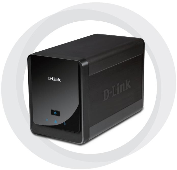
Hardware Overview
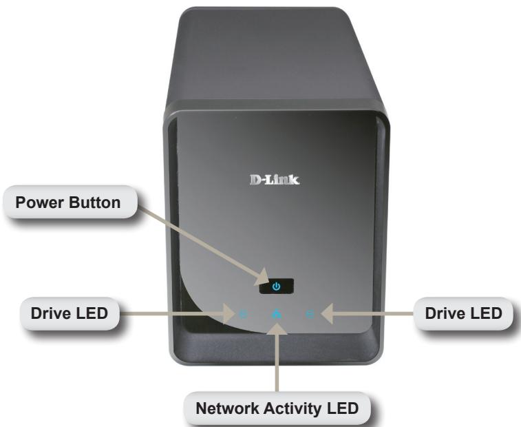
Front View
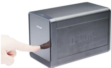
Power Button:
Press once to power on the NVR. Press and hold the button until the LED begins to blink to power down the NVR.
Drive LEDs:
These LEDs will be solid BLUE when the drives are connected but inactive. The LEDs will blink when the drives are being accessed, formatted or synchronized. They will illuminate AMBER if a drive has failed.
Activity LED:
The LED will be solid BLUE when there is an Ethernet connection. It will blink to indicate LAN traffic.
Bottom
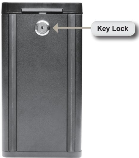
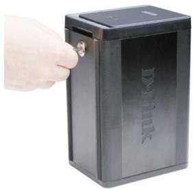
Key Lock:
Use this lock to secure the front panel of the NVR. The panel can be unlocked with the provided key for initial installation.
Rear Panel (Connections)
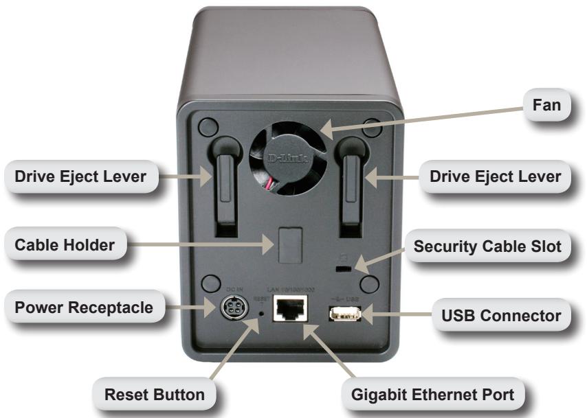
Power Receptacle:
The supplied power adapter connects here.
Gigabit Ethernet Port:
The Gigabit Ethernet port connects the NVR to a network.
Drive Eject Lever:
Use these levers to eject the hard drives. The front panel must be removed before ejecting the drives. Make sure to reset the ejector before installing the new hard drive.
Reset Button:
A pinhole button located beside the Ethernet socket is used to reset the system or restore the factory default settings. To reset, simply press and hold the button until the power LED flashes.
USB Connector:
A UPS can be used as an emergency power supply for the NVR. The UPS can use the USB interface to notify the NVR to perform a proper shutdown before battery power runs out.
Security Cable Slot:
An external lock can be affixed to this slot to prevent theft.
Fan:
The NVR will adjust the system temperature automatically by turning the fan on/off.
Cable Holder:
Holds the power cable to ensure a safe operating environment.
Note: After resetting the unit, you will still be able to access the recorded data on your hard drives.
Connecting Your NVR to the Network
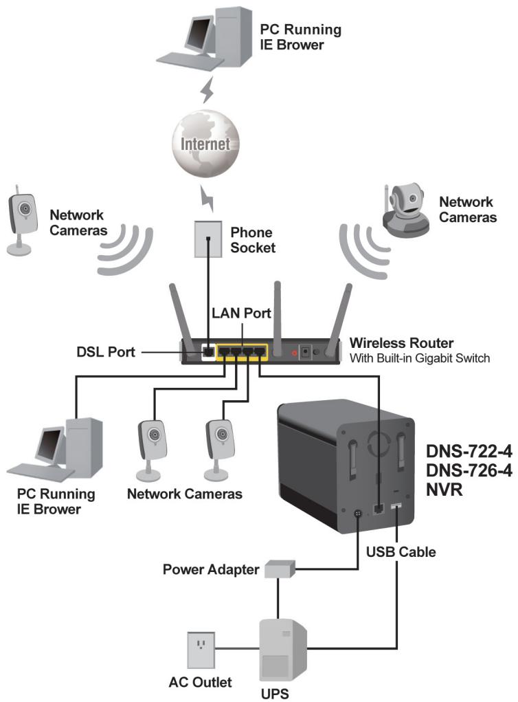
Your Network Setup
Hardware Installation
Install the Hard Drives:
- Please install a SATA HDD before turning on the NVR. Use the key to unlock the faceplate from the bottom of the NVR.
- Slide the faceplate up until it unlatches from the device.
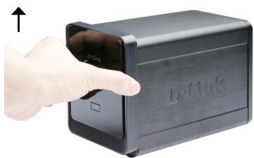
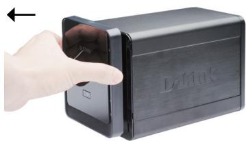
- Once the faceplate is unlatched, pull it off the device, exposing the drive bays.
- Insert a 3.5" SATA hard drive into an available drive bay. Make sure to align the drive connector to the SATA connector on the bottom edge inside the drive bay of the NVR. Gently push the drive in until it connects. When a drive is inserted properly, you will feel it "seat" into the connector. Some hard drives that are thin or oddly shaped may need to be guided carefully into position. If a drive is not properly seated, the LED will not illuminate after powering on the device.
Optional: When installing an optional second HDD, please repeat Step 4. To avoid data incompatibility in RAID 1 operation, useidentical SATA drives from the same manufacturer. Formatted drive capacity for RAID 1 operation is dependant on the HDD with the lowest capacity.
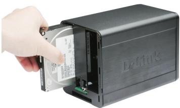
- Attach the faceplate to the front of the device.

- Lock the faceplate to secure the HDDs.

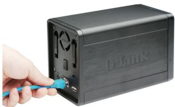
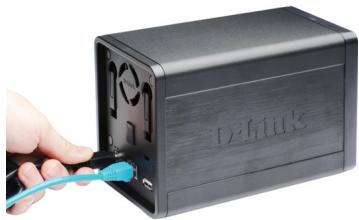
Connect the Ethernet Cable
Connect an Ethernet cable to the Ethernet port. Connect one end of the Ethernet cable to the NVR. Connect the opposite end of this cable to a Gigabit Ethernet LAN port of a router or a switch, or directly to a computer.
Connect the UPS (Optional)
If you have a Universal Power Supply (UPS) that you would like to use with the NVR, you may connect it before powering the unit on.
- Connect the USB cable from the UPS to the port on the back of the NVR.
- Connect the power cable to the UPS. (Ensure that the UPS is plugged in and receiving power.)
Note: To turn off the NVR, simply push the power button for 5 seconds. The power LED will blink and the NVR will turn off after a moment.
Attach the External Power Supply
Attach the external power supply to the DC power receptacle located on the NVR's rear panel (labeled DC12V) and connect the other end to an AC power outlet.
Turn on the Power and Initialize the HDD
Push the power button at the front panel. The LED on the NVR will begin to blink. When you have a proper connection, wait about 60 seconds, the NVR power LED will stay steady and the HDD and network LEDs will begin to blink. The NVR will initialize the HDD to default settings. To change HDD settings, please visit the SETUP page in the web-based configuration utility.
Supported Cameras
DNS-722-4: Supports all D-Link network cameras. Includes support for auto-discovery, and up to 1.3 megapixel resolution.
DNS-726-4: Supports known-brand network cameras including D-Link, Axis, Panasonic, and SONY. Specific feature support depends on software.
Getting Started
Step 1: Make sure the NVR is connected to a network via a router or a switch, or directly connected to PC.
Step 2: Turn on the computer and insert the D-Link DNS-722-4/DNS-726-4 Autorun CD into the CD-ROM drive. The following step-by-step instructions displayed are shown when using Windows Vista operating system. The steps and screens are similar for other Windows operating systems.
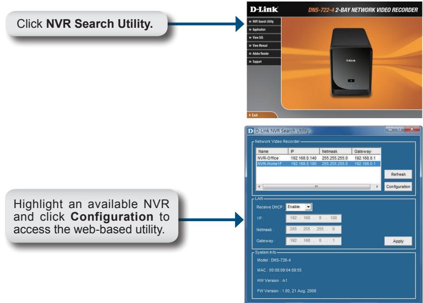
For detailed configuration instructions, please refer to the User Manual on the CD-ROM.
Technical Support
United Kingdom (Mon-Fri)
Home Wireless/Broadband 0871 873 3000 (9.00am-06.00pm, Sat 10.00am-02.00pm)
Managed, Smart, & Wireless Switches, or Firewalls 0871 873 0909 (09.00am - 05.30pm)
(BT 10ppm, other carriers may vary.)
Ireland (Mon-Fri)
All Products 1890 886 899 (09.00am-06.00pm, Sat 10.00am-02.00pm)
€0.05ppm peak, €0.045ppm off peak Times
Internet
http://www.dlink.co.uk
ftp://ftp.dlink.co.uk

E-Mail: support@dlink.at
Telefon: +43(0)820 480084 0,116 € pro Minute
Assistance technique
URL: http://www.dlink.it/support
Notes
D-Link®

Ver. 1.00(E)
2009/01/09
6ENS7264Q.01G