
SR 1301 B - Industrial Cleaner NILFISK - Free user manual and instructions
Find the device manual for free SR 1301 B NILFISK in PDF.

| Product type | Industrial sweeper |
| Brand | NILFISK |
| Model | SR 1301 B |
| Cleaning width (with one side broom) | 1,054 mm |
| Cleaning width (with two side brooms) | 1,308 mm |
| Dimensions (L x W x H) with one side broom | 1,776 x 1,208 x 1,350 mm |
| Total weight in operating order (with operator) | 723 kg |
| Power supply | Batteries 24 V (4 x 6 V 180 Ah or 1 x 24 V 240 Ah, max 330 Ah) |
| Battery type | Lead-acid (WET) or Gel (GEL) |
| Waste container capacity | 130 litres |
| Maximum forward speed | 7 km/h |
| Maximum reverse speed | 3.5 km/h |
| Maximum climbable slope | 16% |
| Minimum turning radius | 1,685 mm |
| Sound pressure level (operator ear) | 67 dB(A) ± 3 dB(A) |
| Suction system motor | 310 W, 3,000 rpm |
| Main broom motor | 500 W, 550 rpm |
| Traction motor | 750 W, 315 rpm |
| Standard dust filter | Paper 15-20 μm, 3.6 m² |
| Container emptying height | 270 - 1,370 mm from floor |
| Working temperature | 0°C to +40°C |
| Working humidity | 30% - 95% |
| Scheduled maintenance | Every 10, 50, 100, 200, 400 hours |
| Safety | Emergency stop button, parking brake, seat micro-switch, thermal fuses |
| Spare parts | Use exclusively original Nilfisk parts |
Frequently Asked Questions - SR 1301 B NILFISK
User questions about SR 1301 B NILFISK
0 question about this device. Answer the ones you know or ask your own.
Ask a new question about this device
Download the instructions for your Industrial Cleaner in PDF format for free! Find your manual SR 1301 B - NILFISK and take your electronic device back in hand. On this page are published all the documents necessary for the use of your device. SR 1301 B by NILFISK.
USER MANUAL SR 1301 B NILFISK
Authorized signatory: Franco Mazzini, General Mgr
Date: Signature:
INHALTSVERZEICHNIS
EINLEITUNG 2
CONSERVATION DU MANUEL 2
DECLARATION DE CONFORMITE 2
DONNEES D'IDENTIFICATION 2
STRUCTURE DE LA MACHINE 6
TABLEAU DE BORD ET COMMANDES 8
ACCESSIONS / OPTIONS 9
CHARACTERISTIQUES TECHNIQUES 9
SCHEMA ELECTRIQUE 11
SCHEMA HYDRAULIQUE 13
UTILISATION 14
CONTROLE / PREPARATION DES BATTERIES SUR UNE MACHINE NEUVE 14
AVANT LA MISE EN MARCHE DE LA MACHINE 15
MISE EN MARCHE ET ARRET DE LA MACHINE 15
MACHINE AU TRAVAIL 16
VIDANGE DU CONTENEUR DECHETS 17
APRES L'UTILISATION DE LA MACHINE 18
REGLAGE DU FEU DE TRAVAIL 18
INACTIVITE PROLONGEE DE LA MACHINE 18
PREMIERE PERIODE D'UTILISATION 18
ENTRETIEN 18
PLAN D'ENTRETIEN PROGRAMME 19
CONTROLE ET REGLAGE DE LA HAUTEUR DU BALAI CENTRAL 20
REEMPLACEMENT DU BALAI CENTRAL 21
CONSERVATION DU MANUEL
STRUCTURE DE LA MACHINE
STRUCTURE DE LA MACHINE (suite)
P100243
TABLEEAU DE BORD ET COMMANDES
ACCESSIONS / OPTIONS
REEMPLACEMENT DU BALAI CENTRAL

REMARQUE
REEMPLACEMENT DU BALAI LATERAL

REMARQUE
MANUAL PURPOSE AND CONTENTS 2
TARGET 2
HOW TO KEEP THIS MANUAL 2
DECLARATION OF CONFORMITY 2
IDENTIFICATION DATA. 2
OTHER REFERENCE MANUALS 3
SPARE PARTS AND MAINTENANCE 3
CHANGES AND IMPROVEMENTS 3
OPERATION CAPABILITIES 3
CONVENTIONS 3
UNPACKING/DELIVERY 3
SAFETY 4
SYMBOLS 4
GENERAL INSTRUCTIONS 4
MACHINE DESCRIPTION 6
MACHINE STRUCTURE 6
CONTROL PANEL 8
ACCESSIONS/OPTIONS 9
TECHNICAL DATA. 9
WIRING DIAGRAM 11
HYDRAULIC DIAGRAM 13
USE 14
BATTERY CHECK/SETTING ON A NEW MACHINE 14
BEFORE STARTING THE MACHINE 15
STARTING AND STOPPING THE MACHINE 15
MACHINE OPERATION 16
HOPPER EMPTYING 17
AFTER USING THE MACHINE 18
WORKING LIGHT ADJUSTMENT 18
MACHINE LONG INACTIVITY 18
FIRST PERIOD OF USE 18
MAINTENANCE 18
SCHEDULED MAINTENANCE TABLE 19
MAIN BROOM HEIGHT CHECK AND ADJUSTMENT 20
MAIN BROOM REPLACEMENT 21
SIDE BROOM HEIGHT CHECK AND ADJUSTMENT 22
SIDE BROOM REPLACEMENT 23
PANEL DUST FILTER CLEANING AND INTEGRITY CHECK 24
CLOSED POCCKET FILTER CLEANING AND INTEGRITY CHECK 25
SKIRTHEIGHT AND OPERATION CHECK 26
HOPPER HYDRAULIC LIFTING SYSTEM OIL LEVEL CHECK 27
BATTERY INSTALLATION/REMOVAL AND BATTERY TYPE SETTING (WET OR GEL) 27
BATTERY CHARGING 28
FUSE CHECK/REplacement/RESET 29
TROUBLESHOOTING 30
SCRAPPING 30
INTRODUCTION

NOTE
The numbers in brackets refer to the components shown in Machine Description chapter.
MANUAL PURPOSE AND CONTENTS
The purpose of this Manual is to provide the operator with all necessary information to use the machine properly in a safe and autonomous way. It contains information about technical data, safety, operation, storage, maintenance, spare parts and disposal. Before performing any procedure on the machine, the operators and qualified technicians must read this Manual carefully. Contact Nilfisk in case of doubts regarding the interpretation of the instructions and for any further information.
TARGET
This Manual is intended for operators and technicians qualified to perform the machine maintenance.
The operators must not perform procedures reserved for qualified technicians. Nilfisk will not be answerable for damages coming from the non-observation of this prohibition.
HOW TO KEEP THIS MANUAL
The User Manual must be kept near the machine, inside an adequate case, away from liquids and other substances that can cause damage to it.
DECLARATION OF CONFORMITY
The declaration of conformity, supplied with the machine, certifies the machine conformity with the law in force.

NOTE
Two copies of the original declaration of conformity are provided together with the machine documentation.
IDENTIFICATION DATA
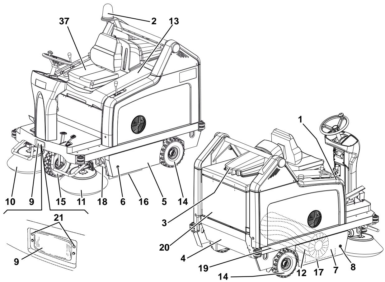
The machine model and serial number are marked on the plate (1).
The machine model year is written in the declaration of conformity and it is also indicated by the first two figures of the machine serial number.
This information is useful when requiring machine spare parts. Use the following table to write down the machine identification data.
MACHINE model
MACHINE serial number
OTHER REFERENCE MANUALS
- Spare Parts List (supplied with the machine)
Service Manual (that can be consulted at Nilfisk Service Centers)
SPARE PARTS AND MAINTENANCE
All necessary operating, maintenance and repair procedures must be performed by qualified personnel or by Nilfisk Service Centers. Only original spare parts and accessories must be used.
Contact Nilfisk for service or to order spare parts and accessories, specifying the machine model and serial number.
CHANGES AND IMPROVEMENTS
Nilfisk constantly improves its products and reserves the right to make changes and improvements at its discretion without being obliged to apply such benefits to the machines that were previously sold.
Any change and/or addition of accessories must be approved and performed by Nilfisk.
This sweeper has been designed and built to clean/sweep smooth and solid floors, and to collect dust and light debris, in civil and industrial environments, under safe operation conditions by a qualified operator.
CONVENTIONS
Forward, backward, front, rear, left or right are intended with reference to the operator's position, that is to say on the driver's seat (37).
UNPACKING/DELIVERY
To unpack the machine carefully follow the instructions on the packing.
Upon delivery check that the packing and the machine were not damaged during transportation. In case of visible damages, keep the packing and have it checked by the carrier that delivered it. Call the carrier immediately to fill in a damage claim.
Check that the machine is equipped with the following features:
-
Technical documents:
-
User Manual
-
Spare Parts List
-
No. 1 150 A main fuse (F0)
- No. 1 10 A fuse
- No. 1 battery charger connector
SAFETY
The following symbols indicate potentially dangerous situations. Always read this information carefully and take all necessary precautions to safeguard people and property.
The operator's cooperation is essential in order to prevent injury. No accident prevention program is effective without the total cooperation of the person responsible for the machine operation. Most of the accidents that may occur in a factory, while working or moving around, are caused by failure to comply with the simplest rules for exercising prudence. A careful and prudent operator is the best guarantee against accidents and is essential for successful completion of any prevention program.
SYMBOLS

DANGER!
It indicates a dangerous situation with risk of death for the operator.

WARNING!
It indicates a potential risk of injury for people or damage to objects.

CAUTION!
It indicates a caution or a remark related to important or useful functions. Pay careful attention to the paragraphs marked by this symbol.

NOTE
It indicates a remark related to important or useful functions.

CONSULTATION
It indicates the necessity to refer to the User Manual before performing any procedure.
GENERAL INSTRUCTIONS
Specific warnings and cautions to inform about potential damages to people and machine are shown below.

DANGER!
Before performing any maintenance, repair, cleaning or replacement procedure disconnect the battery connector, remove the ignition key and engage the parking brake.
- This machine must be used by properly trained operators only. Children or disabled people cannot use this machine.
- Keep the batteries away from sparks, flames and incandescent material. During the normal operation explosive gases are released.
- Do not wear jewels when working near electrical components.
- Do not work under the lifted machine without supporting it with safety stands.
- When working under the open hood, ensure that it cannot be closed by accident.
- Do not operate the machine near toxic, dangerous, flammable and/or explosive powders, liquids or vapours. This machine is not suitable for collecting dangerous powders.
- If the machine is equipped with lead (WET) batteries, battery charging produces highly explosive hydrogen gas. Keep the hood open when charging the batteries and perform this procedure in well-ventilated areas and away from naked flames.
- When lead batteries (WET) are installed on this machine, do not tilt the machine more than 30^ from its horizontal position to not allow the highly corrosive acid to leak out of the batteries. When the machine is to be tilted to perform maintenance procedures, remove the batteries.

WARNING!
- Carefully read all the instructions before performing any maintenance/repair procedure.
Take all necessary precautions to prevent hair, jewels and loose clothes from being caught by the machine moving parts. - When the machine is equipped with lead batteries (WET), don't smoke while charging the batteries.
- To avoid any unauthorized use of the machine, remove the ignition key.
- Do not leave the machine unattended without being sure that it cannot move independently.
- Do not use the machine on slopes with a gradient exceeding the specifications.
- Use only brooms supplied with the machine and those specified in the User Manual. Using other brooms could reduce safety.
Before using the machine, close all doors and/or covers. - Do not use the machine in excessively dusty areas.
- Do not wash the machine with direct or pressurised water jets, or with corrosive substances.
- Do not use compressed air to clean this type of machine, except for the filters (see the relevant paragraph).
While using this machine, take care not to cause damage to other people, and children especially. - Do not put any can containing fluids on the machine.
- The machine storage temperature must be between 0^ and +40^ .
- The machine working temperature must be between 0^ C and +40^ C .
The humidity must be between 30% and 95% .
Always protect the machine against the sun, rain and bad weather, both under operation and inactivity condition. Store the machine indoors, in a dry place. This machine must be used in dry conditions, it must not be used or kept outdoors in wet conditions. - Do not use the machine as a means of transport, or for pushing/towing.
The machine maximum capacity, operator's weight not included, is 110 kg (the weight of waste). - Do not allow the brooms to operate while the machine is stationary to avoid damaging the floor.
In case of fire, possibly use a powder fire extinguisher, not a water one. - Do not bump into shelves or scaffoldings, especially where there is a risk of falling objects.
- Adjust the operation speed to suit the floor conditions.
This machine cannot be used on roads or public streets. - Do not tamper with the machine safety guards.
Follow the routine maintenance procedures scrupulously. - Do not remove or modify the plates affixed to the machine.
In case of machine malfunctions, ensure that these are not due to lack of maintenance. Otherwise, request assistance from the authorised personnel or from an authorised Service Center.
If parts must be replaced, require ORIGINAL spare parts from an Authorised Dealer or Retailer. - To ensure machine proper and safe operation, the scheduled maintenance shown in the relevant chapter of this Manual must be performed by the authorised personnel or by an authorised Service Center.
- The machine must be disposed of properly, because of the presence of toxic-harmful materials (batteries, oils, etc.), which are subject to standards that require disposal in special centres (see the Scrapping chapter).
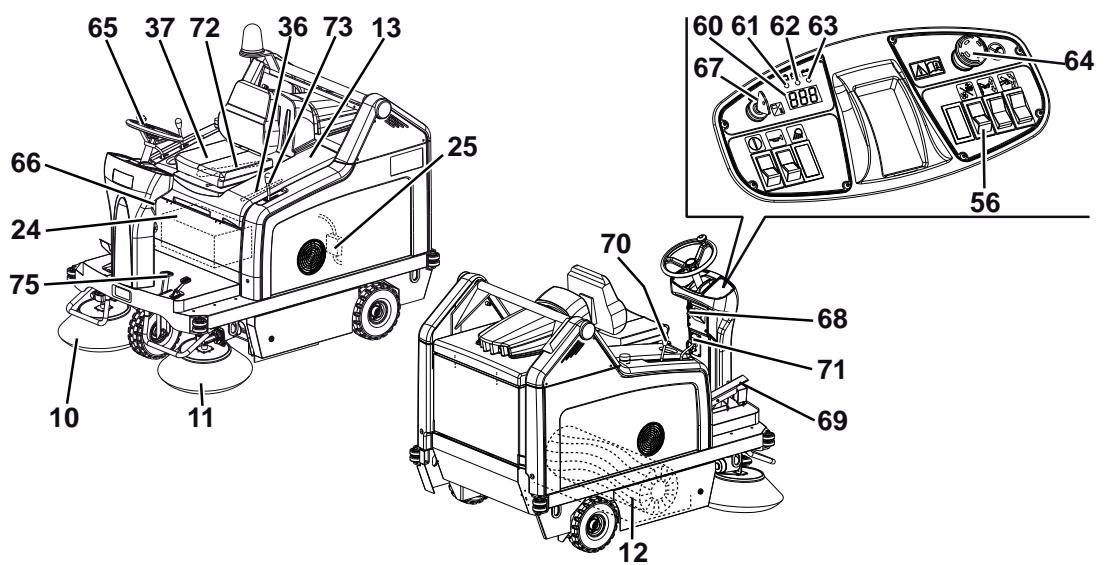
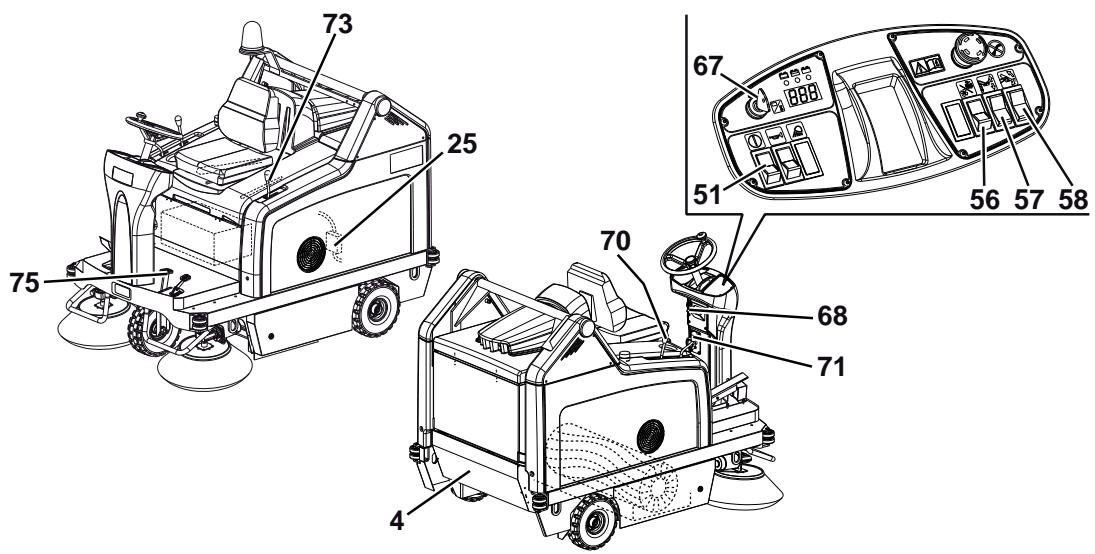
MACHINE DESCRIPTION
MACHINE STRUCTURE
- Serial number plate/technical data/conformity certification
- Flashing light (always on when the ignition key is turned to "I") (optional)
- Vacuum system motor cover
- Hopper (empty it when it is full)
- Left door (to be opened for performing maintenance procedures only)
- Left closing fastener with safety mounting screw
- Right door (for main broom removal)
- Right fastener
- Working light (optional)
- Right side broom
- Left side broom (optional)
- Main broom
- Battery compartment hood
- Rear driving wheels on fixed axle
- Front steering wheel
- Left side skirt
- Right side skirt
- Front skirt
-
Rear skirt
-
Dust filter container
- Working light aiming adjusting screws
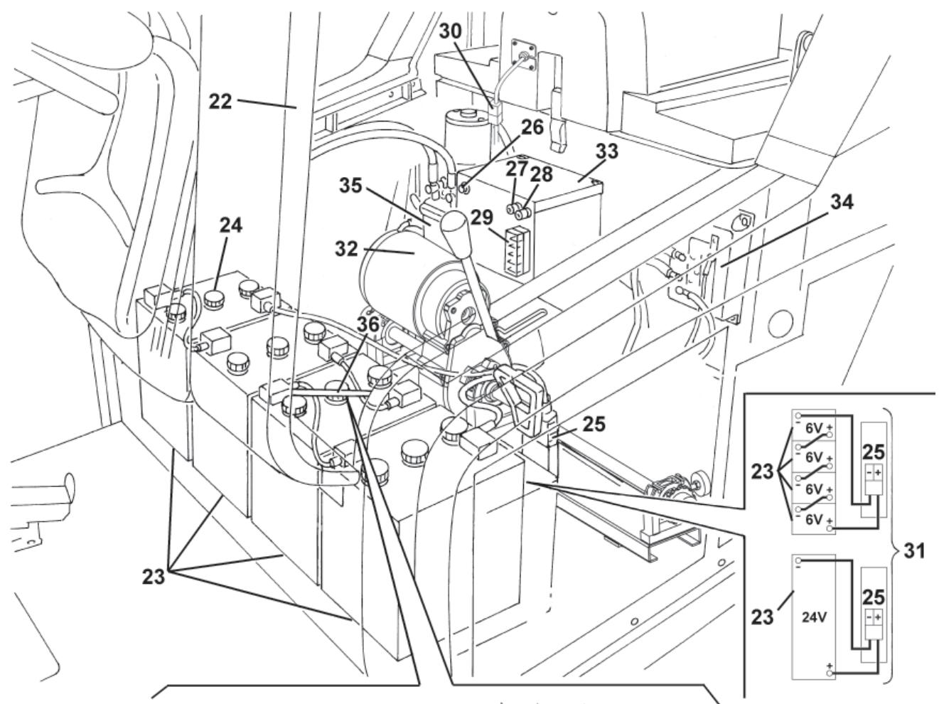
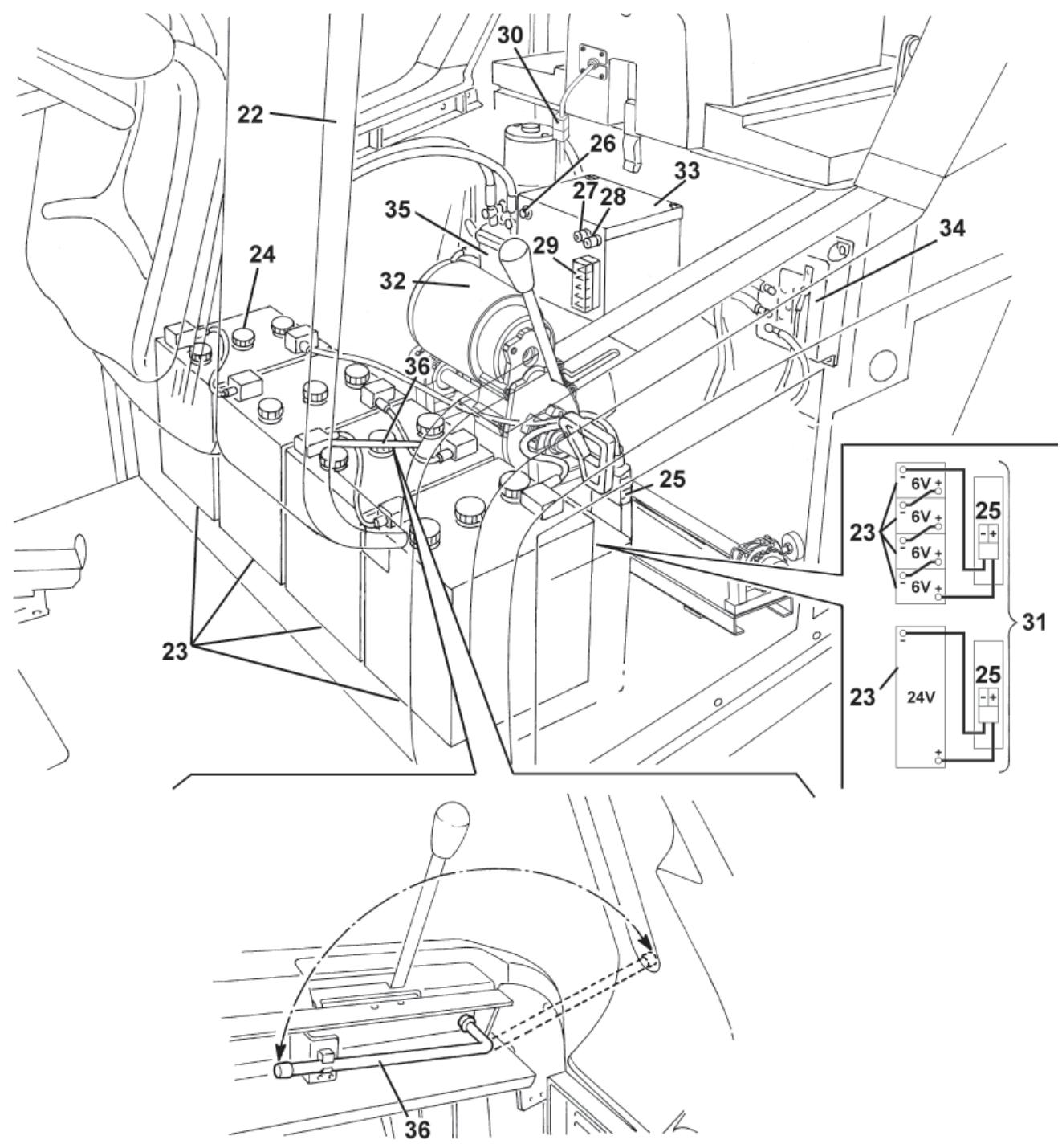
- Battery compartment hood (open)
- Lead batteries (WET) or optional gel batteries (GEL)
- Battery caps (for WET batteries only)
- Battery connector
- Main broom motor resettable thermal fuse
- Right side broom motor resettable thermal fuse
- Left side broom motor resettable thermal fuse (optional)
- Lamellar fuse box
- Vacuum system motor connector
- Battery connection diagram
- Drive system motor
- Electrical component box
- Drive system electronic board
- Hopper hydraulic lifting system oil tank
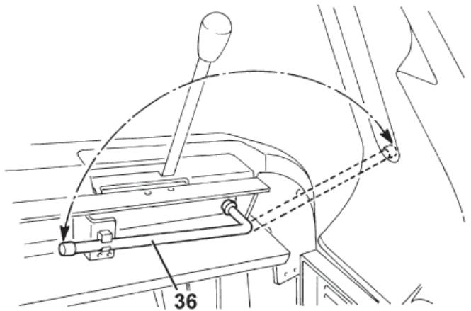
- Hood support rod
- Driver's seat
MACHINE STRUCTURE (Continues)
P100243
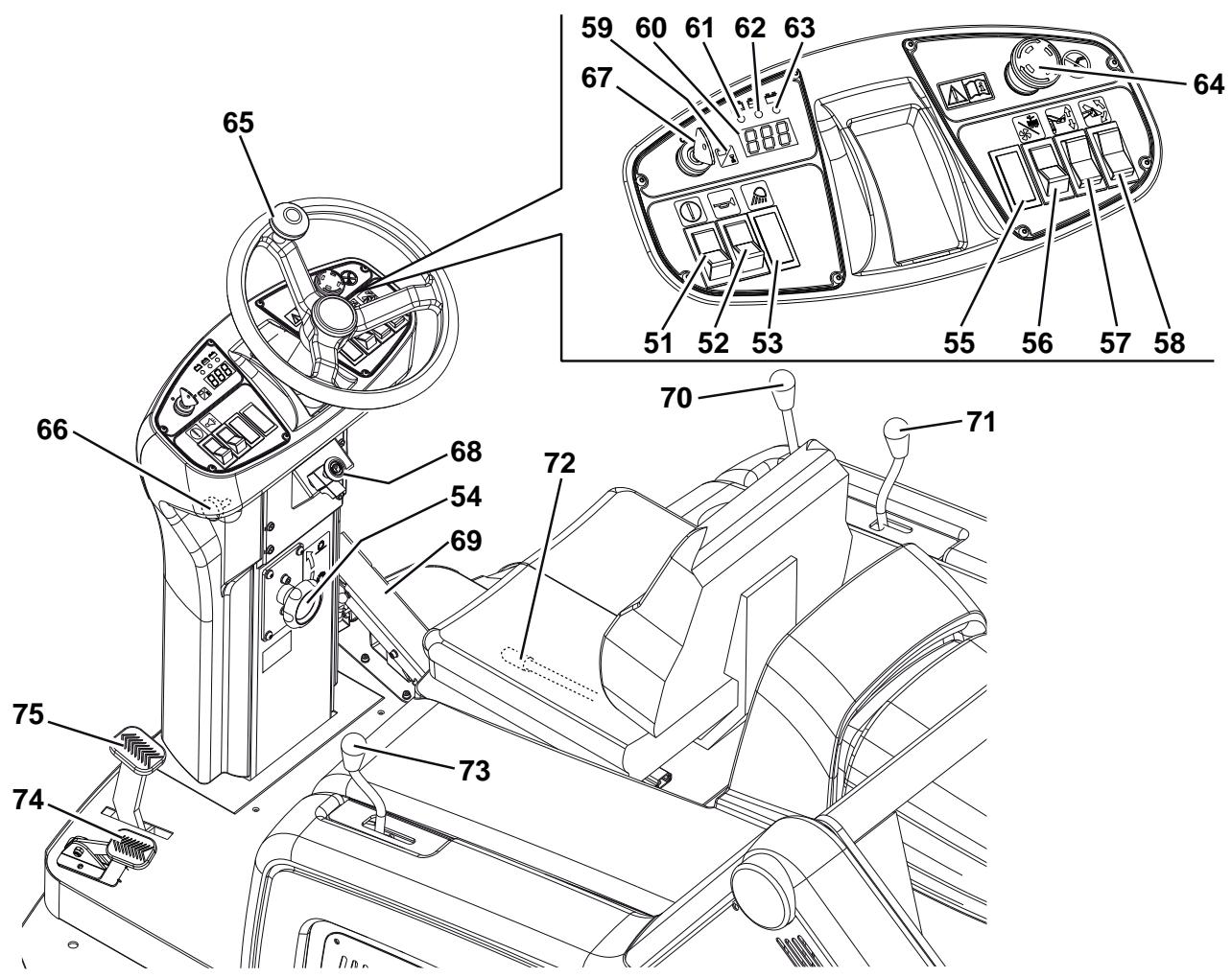
CONTROL PANEL
- Hopper lifting/lowering/dumping enabling switch
- Horn switch
- Working light switch (optional)
-
Main broom print adjusting knob
-
Turn it counter-clockwise to increase the broom print
-
Turn it clockwise to decrease the broom print
-
Position for optional switch
- Switch
(Lower position) vacuum system activation
- (Upper position) filter shaker activation
- Hopper lifting/lowering switch
- Hopper dumping switch
- Display selection switch for the following functions, in sequence:
Working hours
Last digit of the hours - (dot) - minutes
Battery voltage (V)
- Display
- Discharged battery warning light (red) When it is on, the batteries are discharged. The autonomy is over, the batteries must be recharged (see the procedure in the relevant paragraph).
-
Semi-discharged battery warning light (yellow) When it is on, the batteries are semi-discharged. Residual autonomy is few minutes.
-
Charged battery warning light (green) When it is on, the batteries are charged. Residual autonomy depends on battery capacity and working conditions.
- Emergency push-button Press it in case of emergency to stop all the machine functions.
To deactivate the emergency push-button, turn it in the direction shown by the arrow.
- Steering wheel
- Steering wheel tilting control knob
-
Ignition key:
-
When turned to "0", it turns the machine off and disables all functions.
-
When turned to "l", it enables all machine functions; it also turns on the flashing light.
-
Parking brake lock control lever It locks the service brake (75) thus switching it to parking brake.
-
Forward/reverse gear pedal
- Right side broom lifting/lowering lever
- Left side broom lifting/lowering lever (optional)
- Seat longitudinal position adjusting lever
- Main broom lifting/lowering lever
- Front skirt lifting pedal
- Service brake pedal
ACCESSIONS/OPTIONS
In addition to the standard components, the machine can be equipped with the following accessories/options, according to the machine specific use:
- Left side broom
- Main and side brooms with harder or softer bristles
- Antistatic polyester or polyester BIA C dust filter
- Closed pocket filter
- Flashing light
Working light
Non-marking skirts
Non-marking wheels - Protective roof
For further information concerning the optional accessories, contact an authorised Retailer.
TECHNICAL DATA
| General | Values |
| Working width (with one side broom) | 1,054 mm |
| Working width (with two side brooms) | 1,308 mm |
| Machine length | 1,776 mm |
| Machine width (with one side broom) | 1,208 mm |
| Machine width (with two side brooms) | 1,310 mm |
| Machine maximum height (at the steering wheel) | 1,350 mm |
| Minimum distance from the floor (skirts not included) | 60 mm |
| Hopper maximum lifting height | 1,650 mm |
| Maximum weight liftable by the hopper | 110 kg |
| Minimum/maximum dumping height | 270/1,370 mm |
| Minimum turning radius | 1,685 mm |
| Main broom size (diameter x length) | 300 x 800 mm |
| Side broom diameter | 500 mm |
| Maximum forward speed | 7 km/h |
| Maximum reverse speed | 3.5 km/h |
| Gradeability | 16% |
| Hopper capacity | 130 litres |
| Front axle weight in running conditions | 299 kg |
| Rear axle kerb weight | 424 kg |
| Machine kerb weight (with operator) | 723 kg |
| Rear wheel specific pressure on the floor | 1.1 N/mm² |
| Front wheel specific pressure on the floor | 1.1 N/mm² |
| Front steering wheel (diameter x width) | 305 x 92 mm |
| Rear driving wheel (diameter x width) | 305 x 92 mm |
| Sound pressure level at workstation (ISO 11201, ISO 4871) (LpA) | 67 dB(A) ± 3 dB(A) |
| Machine output acoustic power (ISO 3744, ISO 4871) (LwA) | 82 dB(A) |
| Vibration level at the operator's arms (ISO 5349-1) (*) | < 2.5 m/s² |
| Vibration level at the operator's body (ISO 2631-1) (*) | 6.5 m/s² |
(*) Under normal working conditions, on a level asphalt surface.
| Electrical components | Values |
| Electrical system voltage | 24 V |
| Vacuum system motor | 310 W, 3,000 rpm |
| Main broom motor | 500 W, 550 rpm |
| Drive system motor | 750 W, 315 rpm |
| Side broom reduction unit | 90 W, 85 rpm |
| Filter shaker motor | 90 W, 5700 rpm |
| Closed pocket filter shaker motor (optional) | 110 W, 3,000 rpm |
| Batteries | Values |
| Standard WET batteries with acid electrolyte, in serial connection | Four 6 V 180 Ah batteries |
| Optional WET battery with acid electrolyte | One 24 V 240 Ah battery |
| Optional WET or GEL batteries available at any Nilfisk Retailer | Total voltage 24 V |
| Battery maximum capacity | 330 Ah |
| Battery case size (length x width x height) | 800 x 300 x 150 mm |
| Battery compartment maximum size (width x length x height) | 800 x 360 x 380 mm |
| Dust vacuuming and filtering | Values |
| Paper dust filter 15-20 μm | 3.6 m² |
| Main broom compartment vacuum | 10.9 mm/H₂O |
| Hopper hydraulic lifting system | Values |
| Pump | Parker 108 AE S32 - 24 V |
| Maximum pressure | 110 Bar |
| Oil tank capacity | 0.75 litres |
| Hydraulic circuit total capacity | 1.4 litres |
| Hydraulic system oil (at ambient temperature above 10°C) | AGIP Arnica 46 (*) |

CAUTION!
If the machine is to be used at ambient temperatures below +10^ , the oil should be changed with equivalent oil having a viscosity of 32 cSt. For temperatures below 0^ , use an oil with lower viscosity.
(*) See the oil technical data and reference data tables below.
| TECHNICAL DATA | |||
| AGIP ARNICA | 46 | 32 | |
| Viscosity at 40°C | mm²/s | 45 | 32 |
| Viscosity at 100°C | mm²/s | 7.97 | 6.40 |
| Viscosity index | / | 150 | 157 |
| Flash point COC | °C | 215 | 202 |
| Pour point | °C | -36 | -36 |
| Density at 15°C | kg/l | 0.87 | 0.865 |
| REFERENCE DATA |
| ISO-L-HV |
| ISO 11158 |
| AFNOR NF E 48603 HV |
| AISE 127 |
| ATOS Tab. P 002-0/I |
| BS 4231 HSE |
| CETOP RP 91 H HV |
| COMMERCIAL HYDRAULICS |
| Danieli Standard 0.000.001 (AGIP ARNICA 22, 46, 68) |
| EATON VICKERS I-286-S3 |
| EATON VICKERS M-2950 |
| DIN 51524 t.3 HVLP |
| LAMB LANDIS-CINCINNATI P68, P69, P70 |
| LINDE |
| PARKER HANNIFIN (DENISON) HF-0 |
| REXROTH RE 90220-1/11.02 |
| SAUER-DANFOSS 520L0463 |
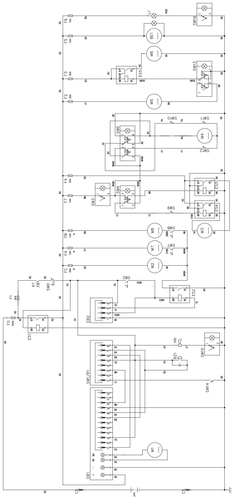
WIRING DIAGRAM
Key
| BE1 | Flashing light (optional) |
| BZ1 | Reverse gear buzzer/horn |
| C1 | Battery connector |
| EB1 | Drive system electronic board |
| EB2 | Display electronic board |
| ES1 | Line electromagnetic switch |
| ES2 | Main broom electromagnetic switch |
| ES3 | Hopper lifting pump relay |
| ES4 | Hopper lowering pump relay |
| ES5 | Vacuum system relay |
| F0 | Main fuse (150 A) |
| F1 | Key fuse (30 A) |
| F2 | Filter shaker fuse (30 A) |
| F3 | Vacuum system fuse (30 A) |
| F4 | Hydraulic pump fuse (30 A) |
| F5 | Flashing light fuse (10 A) |
| F6 | Working light fuse (10 A) |
| F7 | Actuator fuse (10 A) |
| FA | Right side broom circuit breaker (10 A) |
| FB | Left side broom circuit breaker (10 A) (optional) |
| FC | Main broom circuit breaker (30 A) |
| HN | Horn |
| K1 | Ignition key |
| L1 | Working light (optional) |
| M1 | Drive system motor |
| M2 | Main broom motor |
| M3 | Hydraulic pump |
| M4 | Actuator |
| M5 | Filter shaker motor |
| M6 | Vacuum system motor |
| M7 | Right side broom motor |
| M8 | Left side broom motor (optional) |
| R1 | Accelerator potentiometer (built in the pedal) |
| SW0 | Emergency push-button |
| SW1 | Forward/reverse gear switch (built in the pedal) |
| SW2 | Main broom microswitch |
| SW3 | Hopper enabling switch |
| SW4 | Hopper lifting/lowering switch |
| SW5 | Hopper dumping switch |
| SW7 | Right side broom microswitch |
| SW8 | Left side broom microswitch (optional) |
| SW9 | Horizontal hopper microswitch |
| SW10 | Lifted hopper microswitch |
| SW11 | Opened hopper microswitch |
| SW12 | Closed hopper microswitch |
| SW13 | Filter shaker/vacuum system switch |
| SW14 | Driver's seat safety microswitch |
| SW15 | Horn switch |
| SW16 | Working light switch (optional) |
Colour code
| BK | Black |
| BU | Blue |
| BN | Brown |
| GN | Green |
| GY | Grey |
| OG | Orange |
| PK | Pink |
| RD | Red |
| VT | Violet |
| WH | White |
| YE | Yellow |
WIRING DIAGRAM (Continues)
P100245
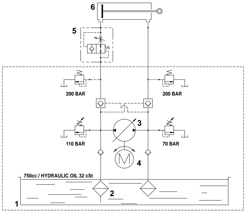
HYDRAULIC DIAGRAM
Key
- Oil tank
- Oil filter
- Pump
- Motor
- Lifting cylinder safety valve
- Hopper lifting cylinder
P100210
USE
P100246

WARNING!
On some points of the machine there are some adhesive plates indicating:
DANGER
WARNING
- CAUTION
CONSULTATION
While reading this Manual, the operator must pay careful attention to the symbols shown on the plates.
Do not cover these plates for any reason and immediately replace them if they are damaged.
BATTERY CHECK/SETTING ON A NEW MACHINE

WARNING!
The electric components of the machine can be seriously damaged if the batteries are either improperly installed or connected. The batteries must be installed by qualified personnel only. According to the type of batteries (WET or GEL), set the electronic board of the machine.
Check the batteries for damage before installation.
Disconnect the battery connector and the battery charger plug.
Handle the batteries with great care.
Install the battery terminal protection caps supplied with the machine.
The machine requires one 24V battery, or four 6 V batteries in serial connection.
The machine can be supplied in one of the following configurations:
a) Batteries already installed and ready to be used
b) Batteries installed on the machine but without electrolyte
c) Without batteries
According to machine configuration, proceed as follows.
a) Batteries already installed and ready to be used
- Open the hood (13) and engage the hood support rod (36).
- Check that the batteries are connected to the machine with the connector (25).
- Disengage the support rod (36) and close the hood.
- Insert the ignition key (67) and turn it to "I", without pressing the pedal (69). If the green warning light (63) turns on, the batteries are charged. If the yellow (62) or red (61) warning light turns on, the batteries must be charged (see the procedure in Maintenance chapter).
b) Batteries installed on the machine but without electrolyte
- Open the hood (13) and engage the hood support rod (36).
- Remove the battery caps (24).

WARNING!
Pay attention when using sulphuric acid, as it is corrosive. If it comes in contact with skin or eyes, rinse thoroughly with water and consult a physician.
Batteries have to be filled in a well-ventilated area. Wear protective gloves.
- Fill the battery cells with sulphuric acid for batteries (density from 1.27 to 1.29kg at 25^ ) according to the instructions shown in the Battery Manual.
- The correct quantity of sulphuric acid is shown in the Battery Manual.
- Let the batteries rest and fill in with sulphuric acid according to the instructions shown in the Battery Manual.
- Charge the batteries (see the procedure in Maintenance chapter).
c) Without batteries
- Buy appropriate batteries (see the Technical Data paragraph).
For the battery choice and installation, apply to qualified battery Retailers. - Install the batteries, then set the machine according to the type of batteries (WET or GEL) (see the procedure in Maintenance chapter).
- Charge the batteries (see the procedure in Maintenance chapter).
BEFORE STARTING THE MACHINE
- Make sure that there are no open doors/hoods and that the machine is in normal operating conditions.
- If the machine has not been used after being transported, check that all the blocks used for the transportation have been removed.
STARTING AND STOPPING THE MACHINE
Starting the machine
- Sit on the driver's seat (37), then adjust the seat in order to reach a comfortable position by using the lever (72).
- Unlock the knob (66) by pulling it, then tilt the steering wheel (65) in order to reach a comfortable position.
After the adjustment, release the knob (66) and slightly move the steering wheel to lock it.
- Sit on the driver's seat (37), insert the ignition key (67) and turn it to "I", without pressing the drive pedal (69), then wait (for a few seconds) for the display (60) to turn on and the working hours to appear.
Check that the green warning light (63) turns on. - If the yellow (61) or red warning light (62) turns on, turn the ignition key to "0" and remove it. Charge the batteries (see the procedure in Maintenance chapter).

NOTE
The seat (37) is equipped with a safety sensor, which allows the machine to be driven only when the operator is on the driver's seat.
- Disengage the parking brake by pressing the pedal (75) and disengaging the lever (68).
- Drive the machine to the working area, by keeping the hands on the steering wheel (65) and pressing the pedal (69) on the front side to move forward and on the rear side to move backward.
The drive speed can be adjusted from zero to maximum speed by increasing the pressure on the pedal.
- Lower the main broom with the lever (73), then turn on the vacuum system by pressing the lower part of the switch (56).
- Lower the right side broom with the lever (70).
- If equipped, lower the left side broom with the lever (71).

NOTE
The brooms (10, 11, 12) can be lowered and lifted even when the machine is moving.
The brooms do not turn when they are lifted.
- Start sweeping by driving the machine with the hands on the steering wheel (65) and by pressing the pedal (69).
Stopping the machine
- To stop the machine, release the pedal (69).
To stop the machine quickly, also press the service brake pedal (75).
In case of emergency, press the emergency push-button (64) to immediately stop the machine.
To deactivate the emergency push-button (64), turn it in the direction shown by the arrow.
- Turn the ignition key (67) to "0" and remove it.
- Engage the parking brake by pressing the pedal (75), then engage the brake lock control lever (68).
MACHINE OPERATION
P100247
- Avoid stopping for a long time with the machine in the same position and the brooms turning: this could create unwanted marks on the floor.
- To collect light and bulky waste materials, lift the front skirt by pressing the pedal (74); take into consideration that the machine vacuum capability is reduced when the front skirt is lifted.

WARNING!
When operating on wet floors, it is essential to turn off the vacuum system by pressing the switch (56) to prevent the dust filter from being damaged.
- For machine proper operation, the dust filter must be as clean as possible. To clean the dust filter while sweeping, turn on the filter shaker for a short interval by pressing the upper part of the switch (56), then turn on the vacuum system by pressing the lower part of the switch (56).
While working, repeat the procedure every 10 minutes on average (depending on the dustiness of the area to be cleaned).

NOTE
This procedure can also be performed when the machine is moving.

CAUTION!
When the dust filter is clogged and/or the hopper is full, the machine cannot collect dust and debris anymore.
- The hopper (4) should be dumped after each working period and whenever it is full (see the procedure in the next paragraph).
HOPPER EMPTYING
- The hopper maximum dumping height is 1,370 mm (see Fig. 2).
-
To empty it, move the machine close to the dustbin and proceed as follows:
-
Lift the side and main brooms.
- Turn off the vacuum system with the switch (56).
- Turn on the filter shaker by pressing the upper part of the switch (56).

WARNING!
Always perform this procedure on a level floor to avoid machine unbalance.

WARNING!
When lifting and emptying the hopper (4), engage the parking brake with the pedal (75) and the lever (68).
- Keep people away from the machine and from the hopper (4) especially.
- Press the enabling switch (51) while pressing the hopper lifting switch (57) to lift the hopper (A, Fig. 1) up to the desired position.
- Press the enabling switch (51) and the dumping switch (58) of the hopper (B, Fig. 2) at the same time, and discharge all the debris in the dustbin (A).

WARNING!
The hopper (A, Fig. 1) can be dumped only when lifted at a minimum height of 270~mm .
- Press the enabling switch (51) and the hopper dumping switch (58) at the same time to bring the hopper back to horizontal position.
- To lower the hopper, press the hopper enabling switch (51) while pressing the hopper lowering switch (57).

WARNING!
The hopper cannot be lowered if it is not brought to horizontal position first.
- The machine is ready to start sweeping again.
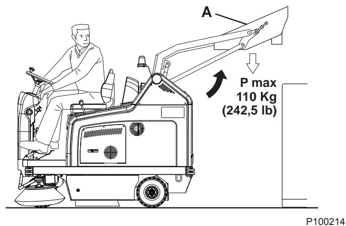
Figure 1
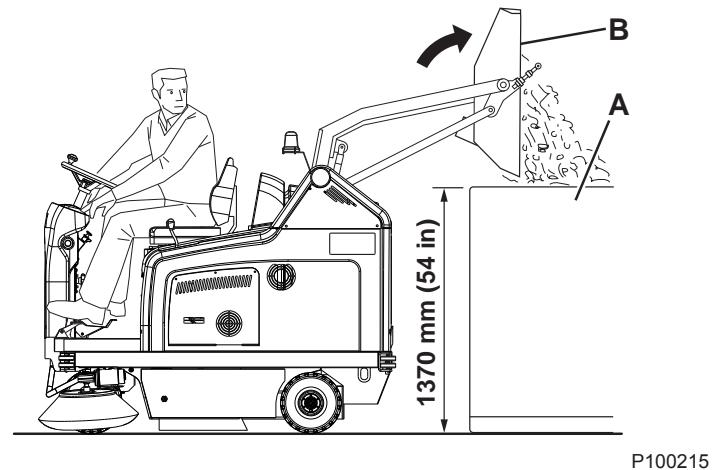
Figure 2
AFTER USING THE MACHINE
After working, before leaving the machine:
- Turn on the filter shaker shortly, by pressing the upper part of the switch (56).
Empty the hopper (4) (see the procedure in the previous paragraph). - Lift the main broom with the lever (73).
- Lift the side brooms with the levers (70) and (71).
- Turn off the machine by turning the ignition key (67) to "0", then remove it.
- Engage the parking brake by pressing the pedal (75), then engage the brake lock control lever (68).
WORKING LIGHT ADJUSTMENT
If necessary, adjust the working light beam aiming (9) with the screws (21).
MACHINE LONG INACTIVITY
If the machine is not going to be used for more than 30 days, proceed as follows:
- Check that the machine storage area is dry and clean.
- Disconnect the battery connector (25).
FIRST PERIOD OF USE
After the first 8 hours, check the machine fastening and connecting parts for proper tightening and check the visible parts for integrity and leakage.
MAINTENANCE
The lifespan of the machine and its maximum operating safety are ensured by correct and regular maintenance.
The following table provides the scheduled maintenance. The intervals shown may vary according to particular working conditions, which are to be defined by the person in charge of the maintenance.
All scheduled or extraordinary maintenance procedures must be performed by qualified personnel, or by an authorised Service Center.
This Manual describes only the easiest and most common maintenance procedures.
For other maintenance procedures shown in the Scheduled Maintenance Table, refer to the Service Manual that can be consulted at any Service Center.

WARNING!
To perform maintenance procedures, the machine must be off, the ignition key removed, and, if necessary, the batteries must be disconnected.
Before performing any maintenance procedure, carefully read the instructions shown in Safety chapter.
SCHEDULED MAINTENANCE TABLE
| Procedure | Upon delivery | Every 10 hours | Every 50 hours | Every 100 hours | Every 200 hours | Every 400 hours |
| Battery fluid level check | (1) | |||||
| Side and main broom height check | ||||||
| Hopper hydraulic lifting system oil level check | (1) | |||||
| Skirt height and operation check | ||||||
| Panel dust filter cleaning and integrity check | ||||||
| Filter shaker operation check | (*) | |||||
| Driving wheel chain cleaning and tension check | (*) | |||||
| Visual inspection of the belt between motor and main broom | (*) | |||||
| Closed pocket filter cleaning and integrity check | ||||||
| Brake adjustment | (*) | |||||
| Nut and screw tightening check | (*)(2) | |||||
| Steering chain cleaning | (*) | |||||
| Vacuum system efficiency check | (*) | |||||
| Replacement of the timing belt between idle gear and main broom | (*) | |||||
| Hopper gasket integrity check | (*) | |||||
| Lifted hopper control microswitch adjustment check | (*) | |||||
| Horizontal hopper control microswitch adjustment check | (*) | |||||
| Motor carbon brush check and replacement | (*) | |||||
| Hydraulic system oil change | (*)(3) |
(*) For the relevant procedure, see the Service Manual.
(1) Or before start-up.
(2) And after the first 8 running-in hours.
(3) Change the hydraulic system oil for the first time after 500 hours, then every 2,000 hours or every year.
MAIN BROOM HEIGHT CHECK AND ADJUSTMENT

NOTE
Brooms with harder or softer bristles are available. This procedure is applicable to all types of brooms.
-
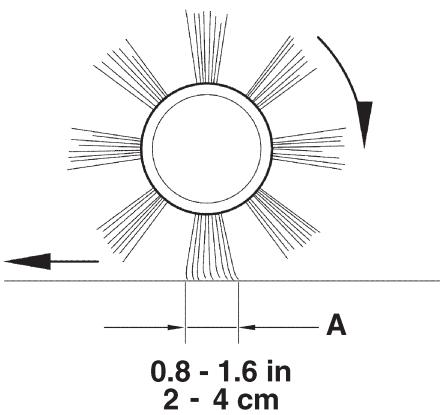
Check the main broom distance from the floor as shown below:
-
Drive the machine on a level floor.
- Keep the machine stationary, lower the main broom and turn it on for a few seconds.
- Stop and lift the main broom, then move the machine and switch it off.
- Check that the main broom print (A, Fig. 3), along its length, is 2 to 4 cm wide.
If the print (A) is not within specifications, adjust the main broom height according to the following procedure.
-
Turn the knob (A, Fig. 4) as shown below:
-
To increase the print width, turn the knob counterclockwise
- To decrease the print width, lift the broom with the lever (73) and turn the knob clockwise

NOTE
The knob can be used both to adjust the print and to adjust the broom according to the bristle wear.
- Perform step 1 again to check the proper adjustment of the main broom height.
- When the broom is too worn to be adjusted, replace it as shown in the next paragraph.

NOTE
If it is not possible to adjust the print (A, Fig. 3) properly, because the pressure on the floor at the ends of the broom is different, refer to the Service Manual.
P100216
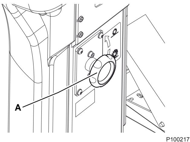
Figure 3
Figure 4
MAIN BROOM REPLACEMENT

NOTE
Brooms with harder or softer bristles are available. This procedure is applicable to all types of brooms.

WARNING!
It is advisable to wear protective gloves when replacing the main broom because there can be sharp debris between the bristles.
- Drive the machine on a level floor and engage the parking brake with the pedal (75) and the lever (68).
- Turn the ignition key (69) to "0" and remove it.
- Release the fastener (8) and open the right door (7).
- Unscrew and remove the knobs (A, Fig. 5).
- Remove the main broom compartment cover (A, Fig. 6).
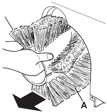
- Remove the main broom (A, Fig. 7).
- Check that the drive hub (A, Fig. 8) is free from dirt or foreign materials (ropes, rags, etc.) accidentally rolled up.
- The new main broom must be installed with the bristles rows (B, Fig. 8) bent as shown in the figure.
- Install the new main broom (C, Fig. 8) and ensure that the mesh (D) correctly fits into the relevant drive hub (A).
- Install the main broom compartment cover (A, Fig. 6) and tighten the knobs (A, Fig. 5).
- Close the right door (7) and engage the fastener (8).
- Check and adjust the main broom height as shown in the previous paragraph.
P100219
Figure 6
P100220
Figure 7
P100218
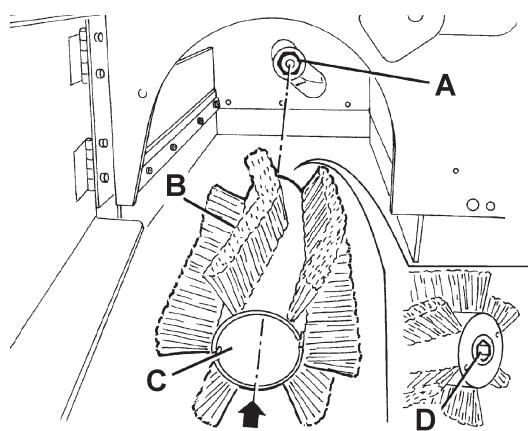
Figure 5
P100221
Figure 8
SIDE BROOM HEIGHT CHECK AND ADJUSTMENT

NOTE
Brooms with harder or softer bristles are available. This procedure is applicable to all types of brooms.
-
Check the side broom distance from the floor, according to the following procedure:
-
Drive the machine on a level floor.
- Keep the machine stationary, lower the side brooms and turn them on for a few seconds.
- Stop and lift the side brooms, then move the machine.
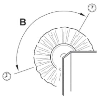
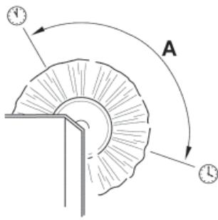
- Check that the side broom prints are as shown in the figure (A and B, Fig. 9).
If the print is not within specifications, adjust the side broom height according to the following procedure.
- Engage the parking brake with the pedal (75) and the lever (68).
- Turn the ignition key (69) to "0".
- Open the hood (22) and fasten it with the support rod (36).
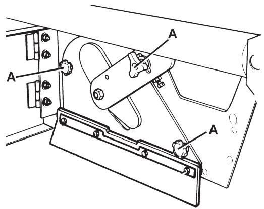
- For the right side broom, operate on the idle gear of the lever (A, Fig. 10), by loosening the ring nut (B) and by adjusting the adjuster (C) until the correct print (A, Fig. 9) is achieved. Then fasten the adjuster with the ring nut (B, Fig. 10).
For the left side broom, operate on the idle gear of the lever (D, Fig. 10), by loosening the ring nut (E) and by adjusting the adjuster (F) until the correct print (B, Fig. 9) is achieved. Then fasten the adjuster with the ring nut (E, Fig. 10).
- Perform step 1 again to check the proper adjustment of the side broom height.
- When the broom is too worn to be adjusted, replace it as shown in the next paragraph.

NOTE
If necessary, the side broom tilting can be adjusted too (see the procedure in the Service Manual).
P100222
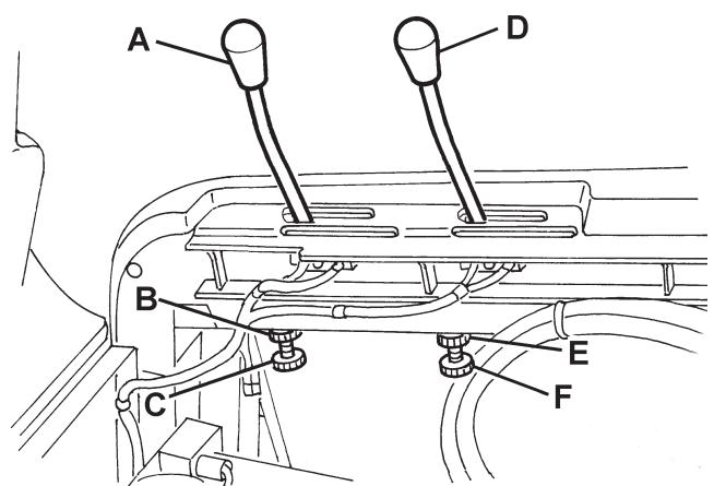
Figure 9
P100223
Figure 10
SIDE BROOM REPLACEMENT

NOTE
Brooms with harder or softer bristles are available. This procedure is applicable to all types of brooms.

WARNING!
It is advisable to wear protective gloves when replacing the side broom because there can be sharp debris between the bristles.
- Drive the machine on a level floor and engage the parking brake with the pedal (75) and the lever (68).
- Turn the ignition key (67) to "0".
- Lift the side broom which has to be removed, with the lever (70) or (71).
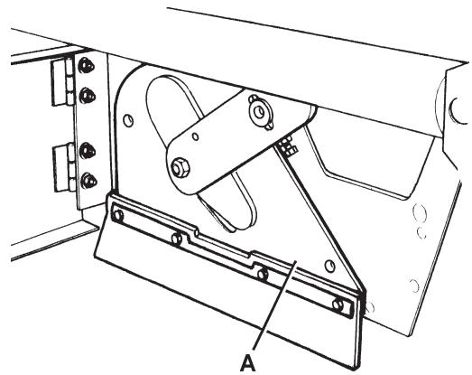
- Remove the screw (A, Fig. 11) inside the side broom, then remove the side broom (B) with the hub (B) by disengaging it from the shaft (C).
Recover the key (D) and the washer (E).
- At the workbench, remove the two screws (F, Fig. 11) and separate the broom (H) from the hub (G).
- Install the new side broom (H, Fig. 11) onto the hub (G), and tighten the screws (F).
- Install the key (D), then install the new side broom with the hub (B, Fig. 11). Install the washer (E) and tighten the screw (A).
- Check and adjust the side broom height as shown in the previous paragraph.
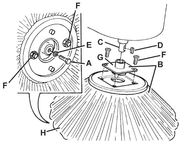
Figure 11
P100224
PANEL DUST FILTER CLEANING AND INTEGRITY CHECK

NOTE
Besides the standard paper filter, polyester filters are also available. The following procedure is applicable to each type of filter.
- Drive the machine on a level floor and engage the parking brake with the pedal (75) and the lever (68).
- Turn the ignition key (67) to "0".
- Open the hood (22) and fasten it with the support rod (36).
- Disconnect the battery connector (25).
- Disconnect the vacuum system motor connector (30).
- Release the fasteners (A, Fig. 12) and remove the vacuum system cover (B).
- Disconnect the connector (A, Fig. 13) from the filter shaker.
- Unscrew the knobs (B, Fig. 13) and remove the filter mounting frame (C).
-
Remove the dust filter (D, Fig. 13).
-
In an outdoor area, clean the filter by shaking it on a level and clean surface, tapping the side (A, Fig. 14) opposite to the wire gauze (B).
Complete the cleaning procedure by using compressed air (C) at maximum 6 Bar, blowing only from the side protected by the wire gauze (B), at a minimum distance of 30~cm .
Check the filter body for tears.
According to the filter type, observe the following cautions:
- Paper filter (standard): Do not use water or detergents to clean it, otherwise it can be damaged.
-
Polyester filter (optional): For a better cleaning, it is allowed to wash the filter with water and non-lathering detergents. This provides better quality cleaning but reduces the life of the filter, which will have to be replaced more frequently. The use of inadequate detergents can damage the filter.
-
If necessary, clean the filter compartment rubber gasket (A, Fig. 15) along its perimeter and check it for integrity. If necessary, replace it.
- Assemble the components in the reverse order of disassembly, and note the following:
Install the filter with the wire gauze (B, Fig. 14) facing upwards.
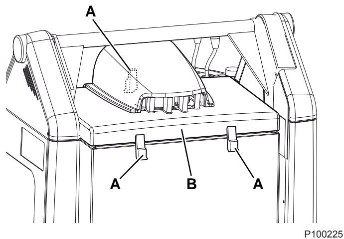
Figure 12
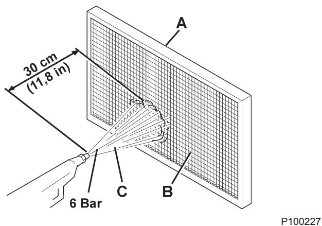
Figure 14
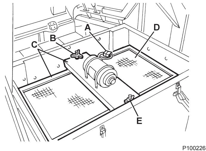
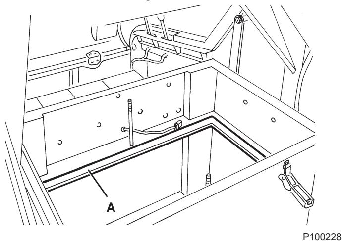
Figure 13
Figure 15
CLOSED POUCHET FILTER CLEANING AND INTEGRITY CHECK

NOTE
The polyester closed pocket filters are normally kept clean by using the filter shaker supplied with the machine.
If necessary, they can be cleaned externally according to the following procedure.
When the filtering surfaces are worn, the filter must be replaced.
- Drive the machine on a level floor and engage the parking brake with the pedal (75) and the lever (68).
- Turn the ignition key (67) to "0".
- Open the hood (22) and fasten it with the support rod (36).
- Disconnect the vacuum system motor connector (30).
- Release the fasteners (A, Fig. 12) and remove the vacuum system cover (B).
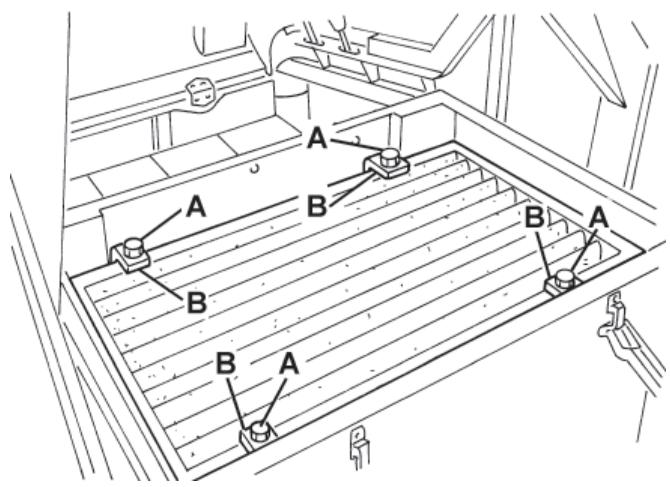
- Unscrew the knobs (A, Fig. 16) and remove the brackets (B).
- Disconnect the filter shaker connector (B, Fig. 17) and remove the dust filter (A).
- In an outdoor area, and with the operator wearing suitable equipment (gloves, mask, glasses), remove the polyester filtering surface, according to the following procedure.
- Remove the filter shaker motor (A, Fig. 18) by unscrewing the two mounting screws.
- Open the filter shaker motor support unit (B, Fig. 18) completely, and release the filtering pocket tension rods (C).
- Remove all the filtering pocket tension rods (D, Fig. 18).
- Open the upper retaining cord (E, Fig. 18) of the closed pocket filter to remove it from the upper frame (F).
- Remove the inner pocket separator (G, Fig. 18).
- Clean the polyester fibber surface (H, Fig. 18) from the dirty side (by using an external vacuum cleaner), spreading it out completely or cleaning pocket by pocket. At the same time, clean both surfaces of the pocket separator (G, Fig. 18), thus removing anything deposited on them. Check the filtering surface for tears and replace it if necessary. It is also possible to use compressed air (maximum 6 Bar), blowing the air from the clean side towards the dirty side.

WARNING!
Do not wash the filter with water. The polyester fibber can shrink and become unusable.
- If necessary, clean the filter compartment rubber gasket (C, Fig. 17) along its perimeter and check it for integrity. If necessary, replace it.
- Assemble the components in the reverse order of disassembly.
P100229
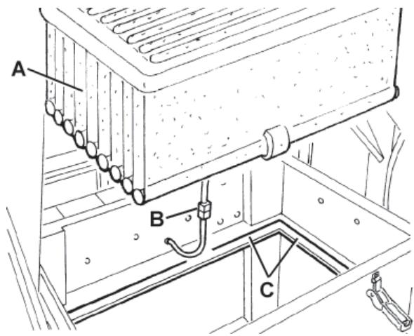
Figure 16
P100230
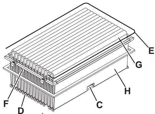
Figure 17
P100231
Figure 18
Preliminary procedure
- Empty the hopper (as shown in the User Manual), because the weight of the waste inside the hopper can affect the skirt height check.
- Drive the machine on a level floor that is suitable for checking the skirt height.
- Engage the parking brake with the pedal (75) and the lever (68).
- Turn the ignition key (67) to "0".
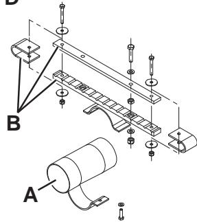
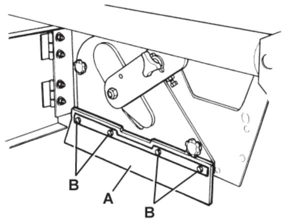
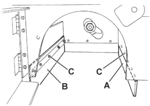
Side skirt check
- Release the fasteners (8 and 6), then open the right and left door (7 and 5).
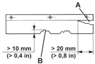
- Check the side skirts (A, Fig. 19) for integrity.
Replace the skirts when they have cuts (A, Fig. 20) larger than 20mm or cracks/tears (B) larger than 10mm (for skirt replacement, refer to the Service Manual).
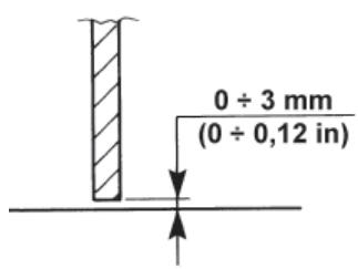
- Check that the distance from the floor of the side skirts (A, Fig. 19) is within 0 - 3mm (see Fig. 21).
If necessary, loosen the screws (B, Fig. 19) and adjust the skirt position. Then tighten the screws (B).
Front and rear skirt check
- Remove the main broom as shown in the relevant paragraph.
- Check the front (A, Fig. 22) and rear skirts (B) for integrity.
Replace the skirts when they have cuts (A, Fig. 20) larger than 20mm or cracks/tears (B) larger than 10mm (for skirt replacement, refer to the Service Manual).
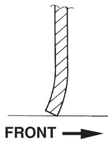
- Check that the front (A, Fig. 22) and rear skirts (B) slightly rub on the floor (see Fig. 24).
If necessary, loosen the screws (C, Fig. 22) and adjust the skirt position. Then tighten the screws (C).
- Press the front skirt lifting pedal (75) completely, and check that the front skirt lifts 5 cm approximately.
Release the pedal and check that the skirt does not remain in an intermediate position but returns to its initial position.
If necessary, adjust the skirt lifting cable (A, Fig. 23) with the adjuster (B) on the left front side of the skirt (for the front skirt control cable replacement, see the Service Manual).
Reset
- Assemble the components in the reverse order of disassembly.
P100232
Figure 19
P100233
P100234
Figure 20
P100235

Figure 23
Figure 21
P100237
Figure 24
HOPPER HYDRAULIC LIFTING SYSTEM OIL LEVEL CHECK

WARNING!
This procedure must be performed with the hopper (4) fully retracted (as shown in the figure).
- Engage the parking brake with the pedal (75) and the lever (68).
- Turn the ignition key (67) to "0".
- Open the hood (22) and fasten it with the support rod (36).
- Check that the oil level in the tank (35) is between the minimum (MIN) and maximum (MAX) marks shown in Fig. 25.
- If necessary, add oil through the plug (A, Fig. 25), using the oil specified in Technical Data paragraph.
- Remove the support rod (36) and close the hood (22).
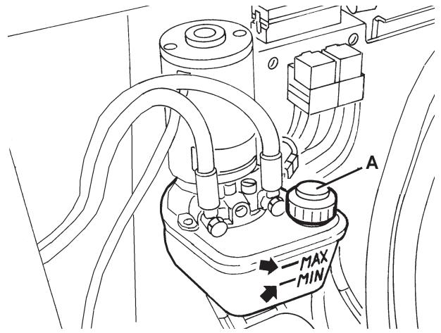
Figure 25
P100245
BATTERY INSTALLATION/REMOVAL AND BATTERY TYPE SETTING (WET OR GEL)

WARNING!
Do not tilt the lead batteries (WET) to prevent the highly corrosive acid from leaking out of the batteries.
Do not connect, not even accidentally, the battery positive and negative terminals by using tools, keys, etc. This could cause dangerous short-circuits.
Battery installation
For approved battery types, see the Technical Data paragraph.
The batteries must be installed as shown in the diagram (31).
According to the battery dimensions, check if it is possible to place them inside the relevant plastic container, supplied with the machine.
If the batteries are larger than the container, use the square guides, supplied with the machine, to ensure the stability inside the battery compartment.

WARNING!
Non-sealed WET batteries always need an appropriate container to prevent the acid form leaking.
Do not install the WET batteries without an appropriate container.
- Engage the parking brake with the pedal (75) and the lever (68).
- Check that the ignition key (67) has been removed.
- Open the hood (22) and fasten it with the support rod (36).
- With the help of an assistant and an appropriate hoisting system, install the batteries (23) as shown in the diagram (31).
- Connect the batteries according to the diagram (31). Do not connect the battery connector (25).
- Set the battery type (WET or GEL), according to the following procedure.
WET or GEL battery setting
- The machine factory setting is for lead batteries (WET). If lead batteries (WET) are installed, do not change the machine settings.
Otherwise, the machine electronic board must be set according to the following procedure.
- Ensure that the battery connector (25) is disconnected.
- Remove the support rod (36) and close the hood (22).
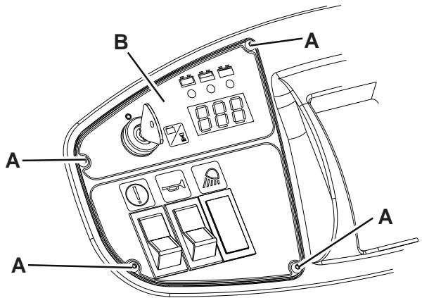
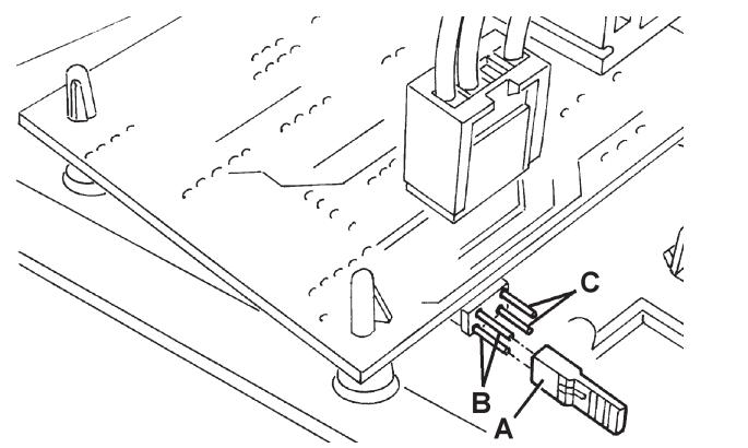
- Remove the screws (A, Fig. 26) and carefully remove the right control panel (B).
- Install a jumper wire (A, Fig. 27) on WET connectors (B) for lead batteries, or on GEL connectors (C) for gel batteries.
- Carefully install the control panel (B, Fig. 26) and the relevant screws (A).
- Open the hood (22), connect the battery connector (25) and close the hood (22).
- If necessary, charge the batteries (see the procedure in the following paragraph).
Battery removal
- Engage the parking brake with the pedal (75) and the lever (68).
- Remove the ignition key (67).
- Open the hood (22) and fasten it with the support rod (36).
- Disconnect the battery connector (25).
- Disconnect the battery wiring harness (23).
- Remove any square guide or bracket fastening the batteries.
- Check that WET battery caps (24) are closed, to prevent the highly corrosive acid from leaking out of the batteries.
- With the help of an assistant and an appropriate hoisting system, remove the batteries (23).
S311445
Figure 26
S311446
Figure 27
BATTERY CHARGING

WARNING!
If the machine is equipped with lead (WET) batteries, battery charging produces highly explosive hydrogen gas. Charge the batteries in well-ventilated areas and away from naked flames. Do not smoke while charging the batteries.
While charging the batteries always keep the hood open.

WARNING!
Pay careful attention when charging lead batteries (WET) as there may be battery fluid leakages. The battery fluid is corrosive. If it comes in contact with skin or eyes, rinse thoroughly with water and consult a physician.
- Drive the machine on a level floor and engage the parking brake with the pedal (75) and the lever (68).
- Turn the ignition key (67) to "0".
- Open the hood (22) and fasten it with the support rod (36).
- (For WET batteries only) check the level of electrolyte inside the batteries (23). If necessary, top up through the caps (24).
Leave the caps (24) open for the next battery charge. If necessary, clean the upper surface of the batteries.
- Check that the battery charger is suitable by referring to the Battery Charger Manual.
The battery charger voltage rating is 24V
Use a battery charger suitable for the type of batteries installed. - Disconnect the battery connector (25) and connect it to the external battery charger.
- Connect the battery charger to the electrical system and charge the batteries.
- After charging, disconnect the battery charger from the electrical mains and from the connector (25).
- Check the electrolyte level and close all caps (24).
- Connect the battery connector (25) to the machine.
- Remove the support rod (36) and close the hood (22). The machine is ready to be used.
FUSE CHECK/REPLACEMENT/RESET
- Drive the machine on a level floor and engage the parking brake with the pedal (75) and the lever (68).
- Turn the ignition key (67) to "0".
- Open the hood (22) and fasten it with the support rod (36).
- Disconnect the battery connector (25).
Lamellar fuse check/replacement
- Remove the cover (A, Fig. 28) and mark the positions of the fuses shown on the adhesive.
- Check/replace the relevant fuse among the following (B):
F1 fuse (30 A): Key circuit
F2 fuse (30 A): Filter shaker
F3 fuse (30 A): Vacuum system
F4 fuse (30 A): Hydraulic pump
F5 fuse (10 A): Flashing light (optional)
F6 fuse (10 A): Working light (optional)
F7 fuse (10 A): Hopper actuator
F8 fuse (30 A): Spare fuse
Main fuse check/replacement
- Remove the screws (C, Fig. 28), then remove the cover (D).
- Remove the nuts (E).
- Check replace the main fuse F0 (150 A) (F)
Circuit breaker check
- Check for deactivation of one of the following fuses, then reset it after the relevant motor has cooled down:
FA fuse (H, Fig. 28): Right side broom motor circuit breaker
- FB fuse (I): Left side broom motor circuit breaker (optional)
- FC fuse (G): Main broom motor circuit breaker
Assembly
- Assemble the components in the reverse order of disassembly.
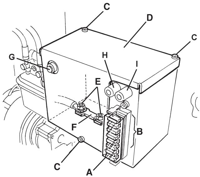
Figure 28
S311447
TROUBLESHOOTING
| Trouble | Possible cause | Remedy |
| When turning the ignition key (67) to "l", the display does not turn on and the machine does not operate. | The battery connector (25) is disconnected. | Connect the battery connector. |
| The F1 and/or F0 fuse is open. | Check the fuses. | |
| The machine does not move when pressing the forward/reverse gear pedal. | The forward/reverse gear pedal has been pressed while turning the ignition key to "l". | Turn the ignition key to "0" and then to "l", and do not press the forward/reverse gear pedal. |
| The main broom does not work. | The circuit breaker (26) is open. | Wait for the main broom motor to cool down, then reset the circuit breaker (26) by pressing the relevant push-button. |
| The side brooms do not operate. | The right side broom circuit breaker (27) or the left side broom circuit breaker (28) is open. | Wait for the side broom motor to cool down, then reset the circuit breaker (27) or (28) by pressing the relevant push-button. |
| The machine operates only when stationary, otherwise the red warning light turns on. | Discharged batteries | Charge the batteries. If the trouble persists, replace the batteries. |
| The battery autonomy is low. | The batteries are no more efficient. | Replace the batteries. If necessary, install batteries with higher capacity (see Technical Data paragraph). |
| The machine collects little debris/dust. | The vacuum system is turned off. | Turn on the vacuum system with the switch (56). |
| The dust filter is clogged. | Clean the dust filter by using the filter shaker or by disassembling it. | |
| The hopper is full. | Empty the hopper. | |
| The skirts are not properly adjusted or are broken. | Adjust/replace the skirts. | |
| The brooms are not properly adjusted. | Adjust the broom height. | |
| The hopper does not lift. | The hydraulic system oil level is incorrect. | Check the hydraulic system oil level in the tank (41). |
| The F4 or F7 fuse is open. | Replace the fuse. | |
| The hopper does not dump. | The F7 fuse is open. | Replace the fuse. |
| The hopper is too low. | Lift the hopper at a minimum height of 300 mm. | |
| The hopper does not lower. | The hopper has not returned to horizontal position after dumping. | Turn the hopper to horizontal position after dumping. |
| In case of particular weather conditions, the hydraulic system oil is slow in flowing through the safety valve. | Wait a few moments to let the hydraulic system oil flow. | |
| The filter shaker does not operate. | The F2 fuse is open. | Replace the fuse. |
For further information, refer to the Service Manual, available at any Nilfisk Service Center.
SCRAPPING
Have the machine scrapped by a qualified scrapper.
Before scrapping the machine, remove and separate the following materials, which must be disposed of properly according to the Law in force:
Batteries
Polyester dust filter
- Main and side brooms
Hydraulic system oil
Hydraulic system oil filter
- Plastic hoses and components
- Electrical and electronic components (*)
(*) Refer to the nearest Nilfisk Center especially when scrapping electrical and electronic components.
INHOUDSOPGAVE
INLEIDING 2
DOEL EN INHOUD VAN DEZE HANDLEIDING 2
BETREFFENDE PERSONEN 2
OPBERGEN VAN DE HANDLEIDING 2
CONFORMITEITSVERKLARING 2
IDENTIFICATIEGEGEVENS 2
ANDERE GEBRUKERSHANDLEIDENGIN 3
VERVANGINGSONDERDELEN EN ONDERHOUD 3
MODIFICATIES EN VERBETERINGEN 3
BEDRIJFSCAPACITEIT 3
ALGEMENE OPMERKINGEN 3
VERPAKKING VERWIJDEREN/AFLEVERING 3
VEILIGHEID 4
GEBRUIKTE SYMBOLEN 4
ALGEMENE INSTRUCTIONS 4
BESCHRIJVING VAN DE MACHINE 6
BOUW VAN DE MACHINE 6
BEDIENINGSPANEEL EN KNOPPEN 8
ACCESSIONS / OPTIES 9
TECHNISCHE EIGENSCHAPPEN 9
ELEKTRISCH SCHEMA 11
HYDRAULISCH SYSTEEM 13
GEBRUIK 14
CONTROLE / VOORBEREIDINGEN VOOR ACCU'S OP EEN NIEUWE MACHINE 14
VOOR HET STARTEN VAN DE MACHINE 15
DE MACHINE STARTEN EN STOPPEN 15
MACHINE IN BEDRIJF 16
DE AFVALCONTAINER LEGEN 17
NA GEBRUIK VAN DE MACHINE 18
DE BEDRIJFSVERLICHTING AFSTELLEN 18
LANGE PERIODE VAN STILLSTAND 18
EERSTE GEBRUIKSPERIODE 18
ONDERHOUD 18
ONDERHOUDSSCHEMA 19
DE HOOGTE VAN DE HOOFDBORSTEL CONTROLLEREN EN AFSTellen 20
DE HOOFDBORSTELVERVANGEN 21
DE HOOGTE VAN DE ZIJBORSTELS CONTROLEREN EN AFSTellen 22
DE ZIJBORSTEL VERVANGEN 23
REINIGING EN CONTROLE OP BESCHADIGING VAN HET STOFPANEELFILTER 24
REINIGING EN CONTROLE OP BESCHADIGING VAN HET ZAKFILTER 25
CONTROLE VAN DE HOOGTE EN WERKING VAN DE FLAPS 26
CONTROLE VAN HET PEIL VAN DE OLIE VOOR HET HYDRAULISCH SYSTEEM VOOR HET HEFFEN VAN DE
AFVALCONTAINER 27
DE ACCU'S MONTEREN/VERWIJDEREN EN HET TYPE ACCU INSTellen (WET OF GEL) 27
ACCU'S OPLADEN 28
CONTROLE / VERVANGING / RESETTEN VAN DE ZEKERINGEN 29
STORINGEN LOKALISEREN 30
VERWIJDERING 30
INLEIDING

OPMERKING
GEVAAR
LETOP
WAARSCHUWING
ADVIES