USER MANUAL MX-10 GRAUPNER
Computer System mx-10
5-Kanal-Fernlenkset in 2,4 GHz Graupner HoTT-Technologie (Hopping Telemetry Transmission)
Computer System mx-10
5-Kanal-Fernlenkset in 2,4 GHz Graupner HoTT-Technologie (Hopping Telemetry Transmission)
Enternung
OUTPUT CH 2: Quer/Höhe links
SUMI (Summensignal IN)
| m/1s
θ.0 | H | RXSQ
θ |
| m/3s
θ.θ | HÖHE | MAX
θm |
| m/10s
θ.0 | T | MIN
θm |

PRX (Power for Receiver)
Best.-Nr. 4136
Safety notes and handling instructions relating
to Nickel-Metal-Hydride rechargeable batteries 75
Foreword 77
Description of radio control set. 78
Recommended battery chargers 80
Transmitter power supply. 81
Receiver power supply 82
Adjusting the stick length. 83
Opening the transmitter case 83
Changing the stick mode 84
Description of transmitter. 86
Transmitter controls 86
Rear of transmitter. 87
Data socket 87
Using the transmitter for the first time. 88
Transmitter firmware update. 89
Using the receiver for the first time 92
Receiver firmware update 94
Installation notes. 96
Receiving system power supply 97
Definition of terms 99
Digital trims and stick calibration 100
Fixed-wing model aircraft. 101
Receiver socket sequence 102
Model helicopters 103
Receiver socket sequence 103
Program descriptions
"Base settings" (model)
Fixed-wing model aircraft 104
Country setting 104
Tail type setting 105
Binding receivers. 106
Range-checking 106
Model helicopter 108
Country setting. 108
Binding receivers. 110
Range-checking 110
"Servo settings" 111
"Fail-Safe" 111
"Telemetry 113
SETTING & DATA VIEW 114
TX display 114
RX Dataview 115
RX Servo. 116
RX Fail Safe 117
RX Free mixers 119
RX Expo. 120
RX Servotest 121
DATA VIEW 124
Receiver 125
General Module. 125
Electric Air Module 125
Vario Module 126
GPS Module. 126
"Trainer mode" 127
Teacher. 127
Pupil 128
Appendix
Appendix 174
Conformity declaration. 202
FCC Information 203
Guarantee certificate 204
Environmental protection
This symbol on the product, in the operating instructions or the packaging indicates that the product must not be discarded via the normal household refuse at the end of its useful life. Instead it must be taken to a collection point for the recycling of electrical and electronic apparatus.
The materials can be re-used according to their identification code. You can make an important contribution to the protection of our shared environment by recycling

old equipment and making use of its basic materials.
Dry and rechargeable batteries must be removed from the device and taken to the appropriate collection point.
Please ask your local authority for the location of your nearest waste disposal site.
The sole purpose of this manual is to provide information; it is subject to amendment without prior notification.
Graupner accepts no responsibility or liability for errors or inaccuracies which may occur in the information section of this manual.
Safety Notes
Please read carefully!
We all want you to have many hours of pleasure in our mutual hobby of modelling, and safety is an important aspect of this. It is absolutely essential that you read right through these instructions and take careful note of all our safety recommendations. We also strongly recommend that you register without delay at http:// www.graupner.de/en/service/productregistration, as this ensures that you automatically receive the latest information relating to your product by e-mail.
If you are a beginner to the world of radio-controlled model aircraft, boats and cars, we strongly advise that you seek out an experienced modeller in your field, and ask him or her for help and advice.
If you ever dispose of this transmitter, these instructions must be passed on to the new owner.
Application
This radio control system may only be used for the purpose for which the manufacturer intended it, i.e. for operating radio-controlled models which do not carry humans. No other type of use is approved or permissible.
Safety notes
SAFETY IS NO ACCIDENT
and
RADIO-CONTROLLED MODELS
ARE NOT PLAYTHINGS
Even small models can cause serious personal injury and damage to property if they are handled incompetently, or if an accident occurs due to the fault of others.
Technical problems in electrical and mechanical systems can cause motors to rev up or burst into life unexpectedly, with the result that parts may fly off at great speed, causing considerable injury.
Short-circuits of all kinds must be avoided at all times.
Short-circuits can easily destroy parts of the radio control system, but even more dangerous is the acute risk of fire and explosion, depending on the circumstances and the energy content of the batteries.
Aircraft and boat propellers, helicopter rotors, open gearboxes and all other rotating parts which are driven by a motor or engine represent a constant injury hazard. Do not touch these items with any object or part of your body. Remember that a propeller spinning at high speed can easily slice off a finger! Ensure that no other object can make contact with the driven components.
Never stand in the primary danger zone, i.e. in the rotational plane of the propeller or other rotating parts, when the motor is running or the drive battery is connected.
Please note that a glowplug engine or electric motor could burst into life accidentally if the receiving system is switched on when you are transmitting the transmitter. To be on the safe side, disconnect the fueltank or the flight battery.
Protect all electronic equipment from dust, dirt, damp, and foreign bodies. Avoid subjecting the equipment to vibration and excessive heat or cold. Radio control equipment should only be used in "normal" ambient temperatures, i.e. within the range -15°C to +55°C.
Avoid subjecting the equipment to shock and pressure.
Check the units at regular intervals for damage to cases and leads. Do not re-use any item which is damaged or has become wet, even after you have dried it out thoroughly.
Use only those components and accessories which we expressly recommend. Be sure to use only genuine matching Graupner connectors of the same design with contacts of the same material.
When deploying cables ensure that they are not under
strain, are not tightly bent (kinked) or broken. Avoid sharp edges, as they can chafe through insulating materials.
Before you use the system, check that all connectors are pushed home firmly. When disconnecting components, pull on the connectors themselves – not on the wires.
It is not permissible to carry out any modifications to the RC system components, as any such changes invalidate both your operating licence and your insurance cover.
Installing the receiving system
In a model aircraft the receiver must be packed in soft foam and stowed behind a stout bulkhead, and in a model boat or car it should be protected effectively from dust and spray.
The receiver must not make direct contact with the fuselage, hull or chassis at any point, otherwise motor vibration and landing shocks will be transmitted directly to it. When installing the receiving system in a model with a glowplug or petrol engine, be sure to install all the components in well-protected positions, so that no exhaust gas or oil residues can reach the units and get inside them. This applies above all to the ON / OFF switch, which is usually installed in the outer skin of the model.
Secure the receiver in such a way that the aerial, servo leads and switch harness are not under any strain. The receiver aerial should be at least 5 cm away from all large metal parts and any wiring which is not connected directly to the receiver. This includes steel and carbon fibre components, servos, electric motors, fuel pumps, cabling of all kinds, etc..
Ideally the receiver should be installed well away from
Safety Notes
any other installed equipment in the model, but in an easily accessible position. Under no circumstances allow servo leads to run close to the aerial, far less coiled round it!
Ensure that cables are fastened securely, so that they cannot move close to the receiver aerial when the model is flying.
Deploying the receiver aerial(s)
The receiver and its aerials should be installed as far away as possible from all kinds of power system. If your model has a carbon fibre fuselage, the aerial tips must always be deployed outside the fuselage. The orientation of the aerial(s) is not critical, but we recommend installing them vertically (upright) in the model. If the receiver features aerial diversity (two aerials), the second aerial should be arranged at 90^ to the first.
Installing the servos
Always install servos using the vibration-damping grommets supplied. The rubber grommets provide some degree of protection from mechanical shock and severe vibration.
Installing control linkages
The basic rule is that all linkages should be installed in such a way that the pushrods move accurately, smoothly and freely. It is particularly important that all servo output arms can move to their full extent without fouling or rubbing on anything, or being obstructed mechanically at any point in their travel.
It is essential that you should be able to stop your motor at any time. With a glow motor this is achieved by adjusting the throttle so that the barrel closes completely when you move the throttle stick and trim to their endpoints.
Ensure that no metal parts are able to rub against each other, e. g. when controls are operated, when parts rotate, or when motor vibration affects the model. Metal-to-metal contact causes electrical "noise" which can interfere with the correct working of the receiver.
Directing the transmitter aerial
Transmitter field strength is at a minimum in an imaginary line extending straight out from the transmitter aerial. It is therefore fundamentally misguided to "point" the transmitter aerial at the model with the intention of obtaining good reception.
When several radio control systems are in use on adjacent channels, the pilots should always stand together in a loose group. Pilots who insist on standing away from the group endanger their own models as well as those of the other pilots.
However, if two or more pilots operating 2.4 GHz radio control systems stand closer together than 5m , the down-link channel may be swamped, triggering a very premature range warning. If this should occur, walk away from the other pilots until the range warning ceases again.
Pre-flight checking
Before you switch on the receiver, ensure that the throttle stick is at the stop / idle end-point.
Always switch on the transmitter first, and only then the receiver.
Always switch off the receiver first, and only then the transmitter.
If you do not keep to this sequence, i.e. if the receiver is at any time switched on when "its" transmitter is switched OFF, then the receiver is wide open to signals
from other transmitters and any interference, and may respond. The model could then carry out uncontrolled movements, which could easily result in personal injury or damage to property.
Please take particular care if your model is fitted with a mechanical gyro: before you switch your receiver off, disconnect the power supply to ensure that the motor cannot run up to high speed accidentally.
As it runs down, the gyro can generate such a high voltage that the receiver picks up apparently valid throttle commands, and the motor could respond by unexpectedly bursting into life.
Range checking
Before every session check that the system works properly in all respects, and has adequate range. Secure the model adequately, and ensure that no persons are standing in front of the model.
Carry out at least one complete function check on the ground, followed by a complete simulated flight, in order to show up any errors in the system and the model's programming. Be sure to read the notes on pages 106 and 110 in this regard.
When operating a model, i.e. when flying or driving, do not operate the transmitter without the aerial fitted. Check that the transmitter aerial is firmly seated.
Operating your model aircraft, helicopter, boat or car Never fly directly over spectators or other pilots, and take care at all times not to endanger people or animals. Keep well clear of high-tension overhead cables. Never operate your model boat close to locks and full-size vessels. Model cars should never be run on public streets or motorways, footpaths, public squares etc..
Checking the transmitter and receiver batteries
It is essential to stop using the radio control system and recharge the batteries well before they are completely discharged. In the case of the transmitter this means – at the very latest – when the message "battery needs charging" appears on the screen, and you hear an audible warning signal.
It is vital to check the state of the batteries at regular intervals - especially the receiver pack. When the battery is almost flat you may notice the servos running more slowly, but it is by no means safe to keep flying or running your model until this happens. Always replace or recharge the batteries in good time.
Keep to the battery manufacturer's instructions, and don't leave the batteries on charge for longer than stated. Do not leave batteries on charge unsupervised. Never attempt to recharge dry cells, as they may explode.
Rechargeable batteries should always be recharged before every session. When charging batteries it is important to avoid short-circuits. Do this by first connecting the banana plugs on the charge lead to the charger, taking care to maintain correct polarity. Only then connect the charge lead to the transmitter or receiver battery.
Disconnect all batteries and remove them from your model if you know you will not be using it in the near future.
Capacity and operating times
This rule applies to all battery types: capacity diminishes with each charge. At low temperatures the battery's internal resistance rises, and capacity falls. This means that its ability to deliver current and maintain voltage is reduced.
Frequent charging, and / or the use of maintenance
programs, tends to cause a gradual reduction in battery capacity. We recommend that you check the capacity of all your rechargeable batteries at least every six months, and replace them if their performance has fallen off significantly.
Use only genuine Graupner rechargeable batteries!
Suppressing electric motors
All conventional (brushed) electric motors generate sparks between the commutator and the brushes, which cause more or less serious interference to the radio control system, depending on the type of motor. If an RC system is to work correctly, it is therefore important to suppress the electric motors, and in electric-powered models it is essential that every motor should be effectively suppressed. Suppressor filters reliably eliminate such interference, and should always be fitted where possible.
Please read the notes and recommendations supplied by the motor manufacturer.
Refer to the main Graupner FS catalogue or the Internet website at www.graupner.de for more information on suppressor filters.
Servo suppressor filter for extension leads
Order No. 1040
Servo suppressor filters are required if you are obliged to use long servo extension leads, as they eliminate the danger of de-tuning the receiver. The filter is connected directly to the receiver input. In very difficult cases a second filter can be used, positioned close to the servo.
Using electronic speed controllers
The basic rule is that the electronic speed controller must be chosen to suit the size of the electric motor it is
required to control.
There is always a danger of overloading and possibly damaging the speed controller, but you can avoid this by ensuring that the controller's current-handling capacity is at least half the motor's maximum stall current.
Particular care is called for if you are using a "hot" (i.e. upgrade) motor, as any low-turn motor (small number of turns on the winding) can draw many times its nominal current when stalled, and the high current will then burn out the speed controller.
Electrical ignition systems
Ignition systems for internal combustion engines can also produce interference, which has an adverse effect on the working of the radio control system.
Electrical ignition systems should always be powered by a separate battery – not the receiver battery.
Be sure to use effectively suppressed spark plugs and plug caps, and shielded ignition leads.
Keep the receiving system an adequate distance away from the ignition system.
Static charges
Lightning causes magnetic shock waves which can interfere with the operation of a radio control transmitter even if the thunderstorm actually occurs several kilometres away. For this reason ...
... cease flying operations immediately if you notice an electrical storm approaching. Static charges through the transmitter aerial can be life-threatening!
Caution
In order to fulfil the FCC RF radiation regulations
Safety Notes
- applicable to mobile transmitting apparatus, the equipment's aerial must be at least 20~cm from any person when the system is in use. We therefore do not recommend using the equipment at a closer range than 20~cm .
- Ensure that no other transmitter is closer than 20~cm from your equipment, in order to avoid adverse effects on the system's electrical characteristics and radiation pattern.
- The radio control system should not be operated until the Country setting has been set correctly at the transmitter. This is essential in order to fulfil the requirements of various directives - FCC, ETSI, CE etc. Please refer to the instructions for your particular transmitter and receiver for details of this procedure.
- Check all working systems and carry out at least one full range check on the ground before every flight, in order to show up any errors in the system and the model's programming.
- Never make any changes to the programming of the transmitter or receiver whilst operating a model.
Care and maintenance
Don't use cleaning agents, petrol, water or other solvents to clean your equipment. If the case, the aerial etc. gets dirty, simply wipe the surfaces clean with a soft dry cloth.
Components and accessories
As manufacturers, the company of Graupner GmbH & Co. KG recommends the exclusive use of components and accessories which have been tested by Graupner and approved for their capability, function and safety. If you observe this rule, Graupner accepts responsibility for the product.
Graupner cannot accept liability for non-approved components or accessories made by other manufacturers. It is not possible for Graupner to assess every individual item manufactured by other companies, so we are unable to state whether such parts can be used without incurring a safety risk.
Liability exclusion / Compensation
It is not possible for Graupner to ensure that the user observes the installation and operation instructions, and the recommended conditions and methods when installing, operating, using and maintaining the radio control components. For this reason Graupner denies all liability for loss, damages or costs which arise through misuse or mishandling of this equipment, or are connected with such use in any way.
Unless obliged by law, Graupner's obligation to pay compensation, regardless of the legal argument employed, is limited to the invoice value of that quantity of Graupner products which were immediately involved in the event in which the damage occurred, unless the company is deemed to have unlimited liability on account of deliberate or gross negligence.
As with all sophisticated technical products, it is vitally important that you observe the following safety notes and handling instructions if you wish the equipment to operate safely and reliably for an extended period.
Safety notes
- Rechargeable batteries are not playthings, and must be kept well away from children.
Store rechargeable batteries out of the reach of children.
- Check that the batteries are in perfect, serviceable condition before every use. Do not re-use defective or damaged batteries.
- Rechargeable batteries must be used within the specified limits stated for the corresponding cell type.
- Do not heat, incinerate or short-circuit rechargeable batteries, and never charge them with excessive currents or reversed polarity.
- Never use rechargeable batteries consisting of parallel-wired cells, combinations of old and new cells, cells of different construction, size, capacity, make, brand or cell type.
- Batteries installed inside equipment should always be removed from the device when it is not in use and not about to be used. Always keep equipment switched off in order to avoid deep-discharged cells. Batteries must be recharged in good time.
- The battery to be charged should be placed on a non-inflammable, heat-resistant, non-conductive surface for the whole of the charge period. Keep inflammable and volatile objects and materials well clear of the charging area.
- Batteries must always be supervised when on charge. Never exceed the maximum fast-charge current
specified for the cell type in use.
- If the battery heats up to more than 60^ whilst on charge, halt the charge process immediately and allow the pack to cool down to about 30^ .
- Never recharge a battery which is already charged, hot, or not completely discharged.
- Do not make any modifications to batteries. Never solder or weld directly to cells.
- If incorrectly handled, rechargeable batteries are at risk of combustion, explosion, corrosive action and burns. Suitable extinguishing materials include fire blankets, CO2 fire extinguishers and sand.
- Escaped electrolyte is corrosive - do not allow it to contact skin or eyes. In an emergency rinse the area immediately with plenty of clean water before seeking medical help.
- The cells' air vents must never be blocked or sealed, e.g. by solder. When soldering, the iron temperature should not exceed 220^ , and each joint should be completed in less than twenty seconds.
- To avoid cell deformation, do not exert excessive mechanical pressure on battery cells.
If a battery should be accidentally overcharged, use the following procedure:
Simply disconnect the battery and leave it on a noninflammable surface (e.g. stone floor) until it has cooled down. Never hold the battery in your hand, as there is a risk that cells might explode.
Always observe the recommended rates for charging and discharging.
The capacity of your rechargeable battery diminishes with every charge / discharge process. Stored batteries
may eventually exhibit reduced capacity.
Storage
Batteries should not be stored in a completely discharged state. Store them in a dry enclosed space at an ambient temperature of +5^ to +25^ . If you are storing a battery for a period longer than four weeks, ensure that the cell voltage does not fall below 1.2 V
Balancing individual battery cells
- To balance new battery cells, i.e. to bring them all to the same state of charge, charge them at what is known as the 'normal' rate until they are full. As a general guideline a fully discharged battery needs to be charged for a period of twelve hours at a current corresponding to one tenth of the capacity printed on the cell label (the "1/10C" method). After this treatment all the cells will be fully charged, and exhibit the same voltage. This method of balancing battery cells should be repeated after every ten fast-charge processes, so that the cells are repeatedly balanced; this helps to ensure an extended useful life for your batteries.
- If you have the facilities to discharge individual cells, we recommend that you make use of this before every charge process. Otherwise the battery pack should be run down to a discharge voltage of 0.9V per cell. For example, this corresponds to a final discharge voltage of 3.6V in the case of the four-cell pack used in the transmitter.
Charging
Ni-MH batteries should only be charged using the specified currents, charge times and temperature range, and should be supervised constantly when on charge. If you do not have access to a suitable fast charger, i.e. one
which allows you to set the charge current accurately, then the battery should always be recharged using the "normal" charge rate of 1/10C; see the example stated above.
Wherever possible, transmitter batteries should always be recharged at the 1/10C rate, in order to avoid differences in cell states. The charge current must never exceed the maximum permissible value stated in the transmitter instructions.
Fast charging
- If your battery charger includes the facility to adjust the Delta Peak charge cut-off voltage, set this value to 5mV per cell. However, most chargers are set to a fixed cut-off value of 15 20mV per cell, which makes them suitable for use with both NiCd and NiMH batteries. If you are not sure about this, please refer to the operating instructions supplied with your charger, or ask at your local model shop whether your charger is also suitable for Ni-MH packs. If in any doubt, charge your batteries at half the stated maximum charge current.
Discharging
All rechargeable batteries sold by Graupner and GM-Racing are suitable for a maximum continuous current load of 6C ... 13C, according to battery type (refer to the manufacturer's specification!). The higher the continuous current load, the shorter the batteries' useful life.
- Use your battery until its performance falls off, or until the low voltage warning is triggered.
Caution:
When stored for a long period, the cell voltage should not be allowed to fall below 1.2 V. This means that you may have to recharge the battery before sto
ring it.
- Reflex charging and charge / discharge (cycle) programs shorten the effective life of batteries unnecessarily, and are only suitable for checking battery quality or "reviving" relatively old cells. It also makes no sense to charge / discharge a battery before using it - unless you simply wish to check its quality.
Disposal of exhausted dry and rechargeable batteries
The German Battery Order places a legal requirement on every consumer to return all used and exhausted dry cells and rechargeable batteries. It is prohibited to dispose of these items in the ordinary domestic waste. At no charge to the user, old dry and rechargeable batteries can be surrendered at local authority collection points, Graupner retail outlets, and any other shop where dry and rechargeable batteries of the same type are sold. You can also send batteries supplied by us to the following address - with adequate pre-paid postage - for disposal:
You can make an important contribution to environmental protection in this way.
Caution:
Damaged batteries may require special packaging before despatch, as some contain highly toxic materials!!!
mx-10 the latest generation of radio control technology
HoTT (Hopping Telemetry Transmission) is the synthesis of expertise, engineering and world-wide testing by professional pilots. The equipment operates on the 2.4 GHz band, and offers bi-directional communication between transmitter and receiver via a down-link channel integrated into the receiver.
The mx-10 HoTT RC system is based on the Graupner/JR mc-24 computer radio control system which was introduced back in 1997. It has been developed specifically for the beginner, but the mx-10 HoTT is still capable of controlling all current model types without problem - whether fixed-wing model or helicopter, model boat or car.
In the area of fixed-wing models it is often necessary to employ complex mixer functions for the control surfaces. Computer technology enables you to activate a vast range of functions to cope with special model requirements – with the simple setting of a „jumper“. With the mx-10 HoTT all you do is select the appropriate model type, and the software then presents you automatically with the appropriate mixer and coupling functions. This means that the transmitter requires no additional modules in order to implement complex coupled functions, and you can forget all about old-fashioned mechanical mixers in the model. Even helicopters can be controlled by a „Flybarless“ system.
The mx-10 HoTT provides an extremely high level of safety and reliability in use.
The beginner quickly becomes familiar with the different functions thanks to the clear, logically arranged program structure.
In theory the Graupner HoTT process allows more than 200 models to be operated simultaneously. Although in practice the mixed operation of different technical sys
tems in the 2.4 GHz ISM band – as required by the approval regulations – reduces this number considerably. Generally, however, it will always be possible to operate even more models simultaneously on the 2.4 GHz band than on the 35 / 40MHz frequency bands which we have used to date. However, the actual limiting factor – as it has always been – is likely to remain the size of the (air-) space available. The simple fact that no frequency control procedure is necessary equates to an enormous gain in safety, especially at flying sites such as gliding slopes where groups of pilots may be distributed over a large area, with nobody in overall control.
The optional Smart-Box provides a simple means of accessing data and programming HoTT receivers. For example, this method can be used to map receiver outputs, distribute control functions to multiple servos, and match servo travels and directions to each other. This manual describes each menu in detail, and also provides dozens of useful tips, notes and programming examples to complement the basic information. Please refer to the Appendix for additional information on the HoTT system. This manual concludes with the transmitter's conformity declaration and guarantee certificate.
Please read the safety notes and the technical information. We recommend that you read right through the instructions with great care, and check all the functions as described in the text. This can be carried out simply by connecting servos to the supplied receiver, and watching their response as you program the transmitter. However, please read the notes on page 96 in this regard. This is the quickest method of becoming familiar with the essential procedures and functions of the mx-10 HoTT.
Always handle your radio-controlled model with a responsible attitude to avoid endangering yourself and others.
The Graupner team wishes you great pleasure and success with your mx-10 HoTT - a radio control system of the latest generation.
Kirchheim-Teck, October 2011
mx-10 Computer System
Five-channel radio control set with Graupner HoTT 2.4 GHz technology (Hopping Telemetry Transmission)

Graupner HoTT technology offers excellent reliability in use, with bi-directional communication between transmitter and receiver, integrated telemetry (with the optional Smart-Box) and ultra-fast response times.
Simplified programming technology with „Jumper“.
- Micro-computer radio control system exploiting the latest Graupner HoTT 2.4 GHz technology
Bi-directional communication between transmitter and receiver
- Ultra-fast response times through direct, ultra-reliable data transmission from the main processor to the 2.4 GHz RF module.
- Telemetry menu (with the optional Smart-Box) for
displaying telemetry data, and programming receiver outputs and optional sensors.
- Short, folding aerial
- Easy programming and accurate setting with toggle switches and a switch key
- 3 switches: a three-position switch for Trainer/pupil-mode, 2 two-position switches for dual rate and channel 5 are already built
- 5 control functions, including 1 switching channel
Servo reverse
- Mode selector for simple switching between stick MODES 1 ... 4 (throttle left / right, etc.) All applicable settings are automatically converted.
- Wing menu: 1 Ail, 2 Ail, V-tail, delta/flying wing
The following settings can only be done via the optional Smart-Box:
- User-selectable servo cycle times for digital servos, min. 10 ms
Servo-control ± 150% for all servo outputs can be set separately for each side (Single Side Servo Throw)
- Sub-trim in the range of ± 125% to adjust the neutral position of all servos
General features of the HoTT system
Simple, ultra-fast binding of transmitter and receiver
- Multiple receivers can be bound per model for parallel operation
- Extremely fast re-binding, even at maximum range
- Two-receiver satellite operation using special cable connection
mx-10 Computer System
Five-channel radio control set with Graupner HoTT 2.4 GHz technology (Hopping Telemetry Transmission)
- Range-check and warning function
- Receiver low-voltage warning on transmitter screen
- Ultra-wide receiver operating voltage range: 3.6V to 8.4V (fully operational down to 2.5V )
- Fail-Safe
- Unrestricted channel assignment (channel-mapping), mixer functions and all servo settings programmable in the Telemetry menu
- Up to four servos can be actuated simultaneously as a block, with a servo cycle time of 10 ms (digital servos only)
- Optimised frequency hopping and broad channel spread for maximum interference rejection
- Intelligent data transmission with corrective function
Real-time telemetry analysis
- More than 200 systems can be operated simultaneously
Future-proof update capability using data interface


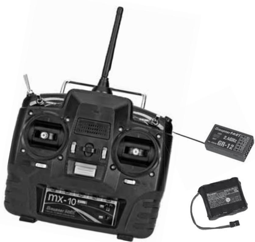
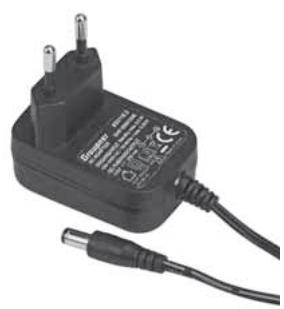
The set Order No. 33110 contains:
mx-10 HoTT micro-computer transmitter with integral 4NH-1500 RX RTU flat-pack Ni-MH transmitter battery (specification reserved), Graupner GR-12 HoTT bi-directional receiver, switch harness and plug-type battery charger
Recommended battery chargers (optional)
| Order No. | Description | 220 V mains conn. | 12 V DC connect. | Suitable for the following battery types | Integral charge, lead |
| NiCd | Ni-MH | LiPo | Lead-ac. |
| 6407 | Multilader 3 | x | | x | x | | | x |
| 6411 | Ultramat 8 | x | x | x | x | x | | |
| 6425 | Twin Charger | x | | | x | | | |
| 6427 | Multilader 3 | x | | x | x | | | x |
| 6455 | Multilader 7E | x | | x | x | | x | |
| 6463 | Ultramat 12 plus Pocket | | x | x | x | x | x | |
| 6464 | Ultramat 14 plus | x | x | x | x | x | x | |
| 6466 | Ultra Trio plus 14 | x | x | x | x | x | x | |
| 6468 | Ultramat 16S | x | x | x | x | x | x | |
| 6470 | Ultramat 18 | x | x | x | x | x | x | |
To recharge the radio system you will also need the transmitter charge lead, Order No. 3022, and the receiver battery charge lead, Order No. 3021, unless stated otherwise in the table.
For details of additional battery chargers, and details of the chargers listed here, please refer to the main Graupner FS catalogue, or our Internet site at www.graupner.de.
Specification, mx-10 HoTT transmitter
| Frequency band | 2,4 ... 2,4835 GHz |
| Modulation | FHSS |
| Transmitter power | see country setting, page 104/108 |
| Control functions | five functions; four with trims |
| Temperature range | -10 ... +55 °C |
| Aerial | folding |
| Operating voltage | 3,4 ... 6 V |
| Current drain | approx. 125 mA |
| Dimensions | approx. 190 x 195 x 90 mm |
| Weight | approx. 630 g with transmitter battery |
Accessories
Order No. Description
1121 Neckstrand, 20 mm wide
70 Neckstrand, 30 mm wide
3097 Wind-shield for hand-held transmitter
Replacement parts
Order No. Description
33112.1 4NH-1500 RX RTU, flat-pack
33800 HoTT transmitter aerial
Specification, GR-12 HoTT receiver
| Operating voltage | 3,6 ... 8,4 V |
| Current drain | ca. 70 mA |
| Frequency band | 2,4 ... 2,4835 GHz |
| Modulation | FHSS |
| Aerial | approx. 145 mm long,
approx. 115 mm encapsu-
lated and approx. 30 mm
active |
| Servo sockets | 6 |
| Sensor socket | 1 (instead of servo 5) |
| Temperature range | approx. -15° ... +70 °C |
| Dimensions | approx. 36 x 21 x 10 mm |
| Weight | approx. 7 g |
Operating Notes
Transmitter power supply
The mx-10 HoTT transmitter is fitted as standard with a high-capacity rechargeable 4NH-1500 RX RTU Ni-MH battery (Order No. 33112.1) (specification reserved).
When delivered, the standard rechargeable battery is not charged.
When you are using the transmitter you can monitor the battery voltage on the Status-LED. If it drops below the in the line „ALARM VOLT“ of the menu „TX“ of the optional Smart Box, page 114, adjustable voltage (default 4.5V ), an audible warning signal starts and the orange Status-LED starts blinking 5 - times in quick succession.
| TX | > |
| ACTION | VOLT: | 05.4V |
| MAXIMUM | VOLT: | 05.5V |
| MINIMUM | VOLT: | 05.4V |
| ALARM | VOLT: | 04.7V |
| COUNTRY | : | GENERAL |
| RANGE TEST | : | OFF 90s |
Always recharge the transmitter battery in good time. When you see this message, cease operations immediately and recharge the transmitter battery.
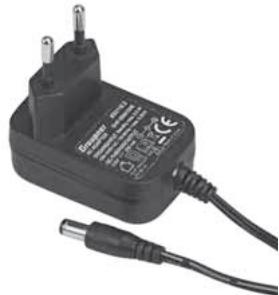
Charging the transmitter battery
The rechargeable Ni-MH transmitter battery can be recharged with the battery charger (Order No. 33116.2) supplied in the set, using the charge socket located on the right-hand side of the transmitter. Leave the battery inside the transmitter for charging, to avoid premature damage to the internal battery socket.
As an approximate guideline a discharged battery should be charged for twelve hours at a current corresponding to one tenth of the capacity printed on the pack. If you are using the standard transmitter battery and the charger supplied in the set, this current is 200mA .
The transmitter must be switched "OFF" for the whole period of the charge process. Never switch on the transmitter when it is still connected to the charger; even a very brief interruption in the process can cause the charge voltage to rise to the point where the transmitter is immediately damaged. For this reason check carefully that all connectors are secure, and are making really good contact.
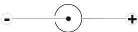
Polarity of the mx-10 HoTT charge socket
Commercially available battery charge leads produced by other manufacturers are often made up with the opposite polarity. For this reason it is essential to use only the genuine Graupner charge lead, Order No. 3022.
Using automatic battery chargers
Although the standard transmitter charge socket is protected against reversed polarity, it is still possible to use suitable chargers to fast-charge the transmitter battery. If possible, set the delta peak voltage difference of your fast charger to a value in the range 10mV ... 20mV or equivalent, as described in the charger's instructions; this ensures that it is suitable for fast-charging Ni-MH cells.
First connect the banana plugs on the charge lead to the charger, and only then connect the other end of the charge lead to the charge socket on the transmitter. When the charge lead is connected to the transmitter, never allow the bare ends of the plugs to touch! To avoid damage to the transmitter, the charge current must never exceed 1 A. If necessary, limit the current on the charger itself.
Removing the transmitter battery
To remove the transmitter battery, first disengage the cover over the battery compartment on the back of the transmitter, then lift it off:
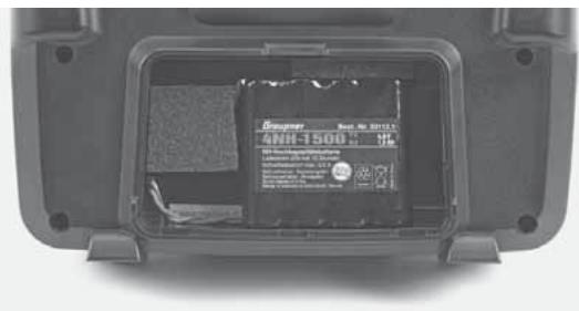
Remove the battery, then carefully pull on the power lead to disconnect the transmitter battery connector.
Installing the transmitter battery
Hold the connector attached to the transmitter battery in such a way that the black or brown wire faces the aerial, and the unused socket of the battery connector is on the side facing the bottom, then push the battery connector onto the three pins projecting out of the inside
of the transmitter, in the direction of the circuit board. (The battery connector is protected against reversed polarity by two chamfered edges; see illustration).
Finally place the battery in the compartment, and close the cover.
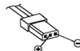
Polarity of transmitter battery connector
Operating Notes
Receiver power supply
A wide range of rechargeable four-cell and five-cell NiMH batteries varying in capacity is available for use as the receiver power supply. If you are using digital servos we recommend that you use a five-cell (6 V) pack of generous capacity. If your model is fitted with a mixture of digital and analogue servos, it is important to check the maximum permissible operating voltage of all the types.
The PRX unit, Order No. 4136, provides a stabilised receiver power supply with a user-variable voltage from one or two receiver batteries; see Appendix.
For reasons of safety battery boxes or dry cells should never be used.
The voltage of the airborne power supply is displayed on the optional Smart-Box screen while the model is flying:
| RX DATAVIEW > |
| S-QUA100%S-dBM-030dBM |
| S-STR100% R-TEM.+28°C |
| L PACK TIME 00010msec |
| R-VOLT:05.0V |
| L.R-VOLT:04.5V |
| SENSOR1:00.0V 00°C |
| SENSOR2:00.0V 00°C |
If the voltage falls below the pre-set warning threshold - 3.8 Volt as standard, but variable in the Telemetry menu; see page 115 - a visual and audible low-voltage warning is triggered.
Nevertheless it is important to check the state of the batteries at regular intervals. Don't put off charging the batteries until the warning signal is triggered.
Note:
Please refer to the main Graupner FS catalogue or visit the Internet site at www.graupner.de for full details of batteries, chargers, measuring equipment and battery monitor units.
Charging the receiver battery
The charge lead, Order No. 3021, can be connected directly to the NC receiver battery for charging. If the battery is installed in a model and you have installed one of the following switch harnesses: Order No. 3046, 3934 or 3934.1 or 3934.3, the battery can be charged via the separate charge socket, or the charge socket which is built into the switch. The switch on the switch harness must be left at the "OFF" position for charging.
Polarity of the receiver battery connector
General notes on battery charging
- Observe the recommendations provided by the charger manufacturer and the battery manufacturer at all times.
- Keep to the maximum permissible charge current stated by the battery manufacturer.
- The maximum charge current for the transmitter battery is 1.5 ~A . Limit the charge current to this value on the charger.
- If you wish to charge the transmitter battery at a current higher than 1.5 ~A , you must first remove the pack from the transmitter, otherwise you risk damaging the circuit board through overloading the conductor tracks, and / or overheating the battery.
- Carry out a series of test charges to ensure that the automatic charge termination circuit works correctly with your battery. This applies in particular if you wish to charge the standard Ni-MH battery using an automatic charger designed for Ni-Cd batteries.
-
You may need to adjust the Delta Peak trigger voltage, if your charger provides this option.
-
Do not discharge the battery or carry out a battery maintenance program via the integral charge socket. The charge socket is not suitable for this application.
- Always connect the charge lead to the charger first, and only then to the transmitter or receiver battery. Observing this rule eliminates the danger of accidental short-circuits between the bare contacts of the charge lead plugs.
- If the battery becomes hot when on charge, it is time to check the pack's condition. Replace it if necessary, or reduce the charge current.
- Never leave batteries unsupervised when on charge.
Environmental protection notes
Important information on the disposal of dry and rechargeable batteries:
The German Battery Order places a legal requirement on every consumer to return all used and exhausted dry cells and rechargeable batteries. It is prohibited to dispose of these items in the ordinary domestic waste. At no charge to the user, old dry and rechargeable batteries can be surrendered at local authority collection points, Graupner retail outlets, and any other shop where dry and rechargeable batteries of the same type are sold. You can also send batteries supplied by us to the following address - with adequate pre-paid postage - for disposal:
You can make an important contribution to environmental protection in this way.
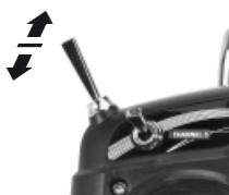
Adjusting stick length
Both sticks are infinitely variable in length over a broad range, enabling you to set them to suit your personal preference.
Hold the bottom half of the knurled grip firmly, and unscrew the top section:
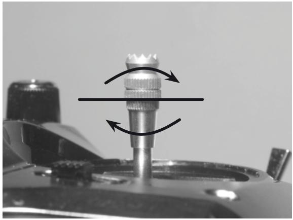
Now screw the stick top in or out (shorter or longer) to the length you prefer before tightening the top and bottom sections against each other to fix the stick top.
Opening the transmitter case
Please read the following notes carefully before you open the transmitter. If you have no experience in such matters, we recommend that you ask your nearest Graupner Service Centre to carry out the work for you. The transmitter should only be opened in the following cases:
- When a self-neutralising stick needs to be converted to non-neutralising action, or a non-neutralising stick to a self-neutralising action.
- If you wish to adjust the stick centring spring tension. Before opening the transmitter check that it is switched off (move Power switch to "OFF").
Open the battery compartment and remove the transmitter battery as described on the previous double page. After this, use a PH1-size cross-point screwdriver to undo the six screws recessed into the back panel of the transmitter, as shown in the illustration:
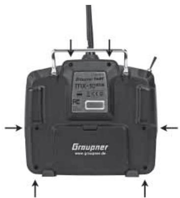
Arrangement of the case back screws
Hold the two case sections together with your hand, and turn the unit over to allow these six screws to fall out onto the table. Now carefully raise the case back and fold it open to the right, as if you were opening a book.
CAUTION
Two multi-core cables connect the lower shell to the transmitter electronics located in the top section. Please take great care not to damage this cable!
Important:
- Do not modify the transmitter circuit in any way, as this invalidates your guarantee and official approval for the system.
- Do not touch any part of the circuit boards with any metal object. Avoid touching the contacts with your fingers.
- Never switch the transmitter on while the case is open.
Please note the following points when closing the transmitter:
- Make sure that no cables are jammed between the transmitter case sections when you close the back.
- Check that the two case sections fit together flush all round before fitting the retaining screws. Never force the two case components together.
- Fit the case screws in the existing threads, and tighten them gently. Over-tightening them will strip the threads in the plastic.
- Remember to re-connect the battery.
Operating Notes
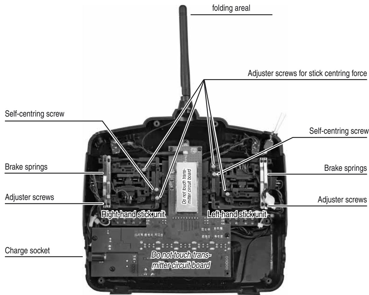
Converting the dual-axis stick units
Self-centring action
Either or both sticks can be converted from self-neutralising to non self-neutralising action: start by opening the transmitter as described on the previous page. If you wish to change the standard stick unit arrangement, start by locating the screw on the left-hand stick unit shown circled in white in the photo below.
Note:
The right-hand stick unit is of mirror-image construction, i.e. the screw you require is located on the right, below centre.
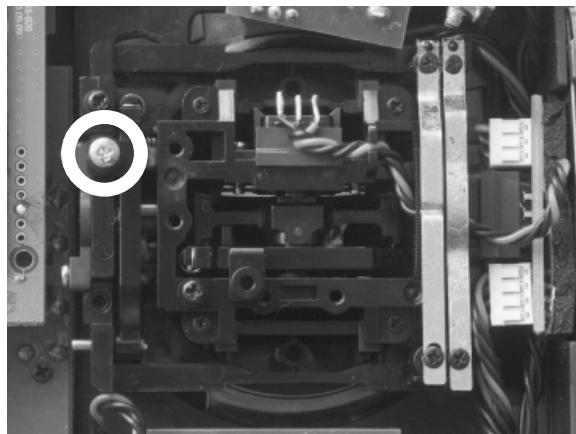
Turn this screw clockwise until the stick on that side moves freely from one end-stop to the other; alternatively unscrew it until the stick is fully self-centring again.
Brake spring and ratchet
You can alter the braking force of the stick by adjusting the outer of the two screws circled in white in the next picture; adjusting the inner screw alters the strength of the ratchet:
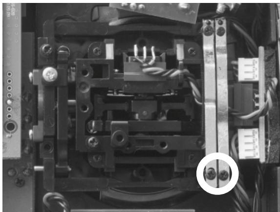
Note:
The right-hand stick unit is of mirror-image construction, i.e. the screw you require is located on the right, below centre.
Stick centring force
The centring force of the sticks is also variable to suit your preference. The adjustment system is located adjacent to the centring springs; see the white circles in the following photo.
You can set the preferred centring spring force by rotating the corresponding adjuster screw using a cross-point screwdriver:
- Turn to the right = harder spring tension;
- Turn to the left = softer spring tension.
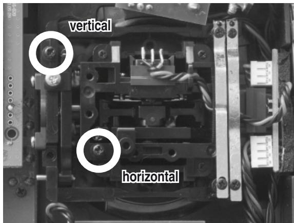
Note:
The right-hand stick unit is of mirror-image construction, i.e. the screw you require is located on the right, below centre.
Description of transmitter
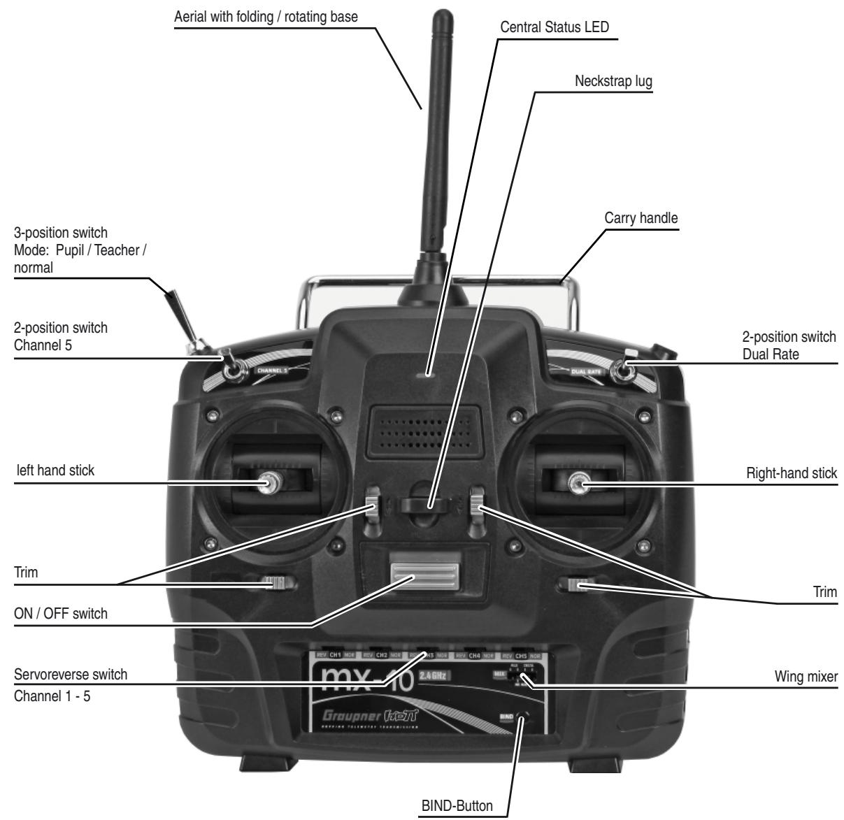
Transmitter controls
Attaching the transmitter neckstrap
You will find a strap lug mounted in the centre of the front face of the mx-10 HoTT transmitter, as shown in the drawing on the right. This lug is positioned in such a way that the transmitter is perfectly balanced even when suspended from a neckstrap.
Order No. 1121 Neckstrap, 20mm wide
Order No. 70 Neckstrap, 30~mm wide
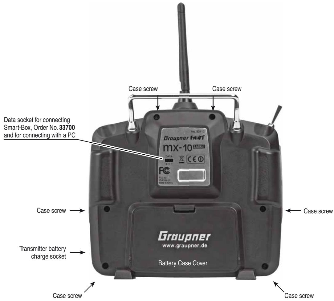
Data socket
For connecting the optional Smart-Box, Order No. 33700.
The Smart Box allows many other HoTT functions such as Servo curve, servo travel, cycle time or channel mapping and HoTT telemetry - see the section „telemetry“ on page 113.
For more details about the Smart-Box please refer to the main Graupner FS catalogue, or refer to that product on the Internet at www.graupner.de.
This socket can be used also to connect the transmitter to a PC running Windows XP, Vista or 7 using the optional USB adapter, Order No. 7168.6 and the connecting lead, Order No. 7168.6A.
The software required at the PC, including a suitable USB driver, can be found in the Download section for the corresponding product at www.graupner.de.
Once you have installed the software required, you can also update the transmitter via this connection.
Using the transmitter for the first time
Preliminary notes regarding the mx-10 HoTT transmitter
Preliminary notes
In theory the Graupner HoTT system permits the simultaneous operation of more than 200 models.
However, in practice the mixed operation of different technical systems in the 2.4 GHz ISM band - as required by the approval regulations - reduces this number considerably. Generally, however, it will always be possible to operate even more models simultaneously on the 2.4 GHz band than on the 35 / 40MHz frequency bands which we have used to date. However, the actual limiting factor - as it has always been - is likely to remain the size of the (air-) space available. The simple fact that no frequency control procedure is necessary - a great convenience in itself - equates to an enormous gain in safety, especially at flying sites where groups of pilots may be distributed over a large area, with nobody in overall control.
Battery charged?
When you take receipt of your transmitter, the battery will be in the discharged state, so you must first charge it as described on page 81. Otherwise you will hear a warning signal and the Status-LED flashes five times in quick succession when falling below a certain voltage to remind you to recharge it.
This warning threshold for the transmitter battery can be selected in the menu „TX“ of the optional the Smart Box, page 114.
Switching the transmitter on
After switching on the Status-LED glows constantly or is blinking to indicate the current transmitter mode.
See the following table:
| LED Status | Buzzer | Description |
| green LED on | - | Transmitter ON, but no bounded receiver or receiver bound, but no telemetry signal |
| orange LED on | - | Transmitter mode „normal“, country setting: general |
| orange LED flashes | - | Transmitter mode „normal“, country setting: France |
| orange LED flashes once | beeping twice after swit-ching on | Transmitter mode: pupil |
| orange LED flashes twice | 2x beeping twice after switching on | Transmitter mode: teacher |
| orange LED flashes three times | beeping three times after switching on | Bad receiving quality of the receiver |
| orange LED flashes four times | beeping four times after switching on | Bad receiving quality of the downlink channel |
| orange LED flashes five times | beeping five times after switching on | Transmitter battery empty. Hit the battery warning threshold, 4.5 V as standard, set in the menu „TX“ of the optional Smart-Box, page 114 |
First select the transmitter mode „normal“, „teacher“ or „pupil“ by the transmitter mode switch on the left top side of the transmitter:
Mode normal
teacher
pupil
The transmitter is delivered in the mode „normal“. For normal operation you have to change nothing. In order to select the teacher or pupil mode, read the chapter „Trainer model“ on page 127.
To change the mode, move the mode switch on the transmitter in the desired position, press and hold the BIND-button and then switch on the transmitter.
Note: after programming the „normal“ mode, the transmitter is in fail-safe programming mode (see page 111), if you do not want to program anything here, turn off the transmitter again now.
The programmed mode is indicated with LED and buzzer signals after switching on the transmitter, see the table above.
Transmitter firmware update
Important notes:
- The transmitter included in the set is prepared at the factory with the correct settings for most European countries (except France).
If you wish to operate the RC system in France, you MUST first set the Country setting on the transmitter to "FRANCE" mode; see page 104 or 108. IT IS PROHIBITED to use the system IN FRANCE using the Universal / EUROPE mode!
- You can operate up to five servos using the mx-10 HoTT transmitter and the receiver supplied in the set, which is already bound to the transmitter.
- When switching on, binding or setting up the radio control system, please ensure at all times that the transmitter aerial is an adequate distance from the receiver aerials. If the transmitter aerial is too close to the receiver aerials, the receiver will be swamped, and the green LED on the receiver will go out. At the same time the down-link channel will stop working. In parallel the orange status LED blinks four times in quick succession and starts the corresponding buzzer warnings. At the same time the radio control system switches to Fail-Safe mode.
If this should happen, simply increase the distance between transmitter and receiver until the displays revert to "normal".
Firmware update
Firmware updates for the transmitter are carried out at the owner's discretion using the three-pin PC interface on the back of the transmitter, in conjunction with a PC running Windows XP, Vista or 7. To connect the transmitter to a PC you also require the optional USB adapter, Order No. 7168.6 and the connecting lead, Order No. 7168.6A.
The latest software and information can be found in the Download section for the corresponding product at www.graupner.de.
Note:
Once you have registered your transmitter at http://graupner.de/de/service/produktristierung you will automatically be informed of new updates by e-mail as they become available.
Updating the mx-16 HoTT software
Attention:
It is essential to check the state of charge of your transmitter battery before carrying out any update. To be on the safe side we recommend that you give the battery a full charge.
1. Installing the driver
In order to be able to use the transmitter's integral port you must first install the driver software required, which is included in the program packages in the "USB driver" folder.
Start the driver installation by double-clicking on the appropriate file and following the on-screen instructions. When the installation is complete, your comput
er must be re-started. The driver only has to be installed once.
2. Connecting the transmitter to the PC
Make sure the transmitter is switched off, then connect the USB lead to the 3-pole socket on the back of the transmitter. Install the cable so that the orange cord shows to the left (center of the transmitter) and the brown cord to the right edge of the transmitter. Do not apply excessive force.
3. Updating the mx-16 HoTT transmitter software
Start the program "Firmware_Uptage_grStudio_Ver-SX.X.exe" from the appropriate folder by a double-click. (The at the time of printing this manual current version 1.3 starts without prior installation.)
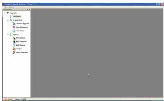
Select "Port Setup" under "Menu"; alternatively open the "Controller Menu" and click on "Port select":
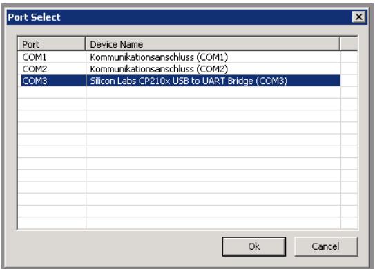
In the "Port select" window you can now select the correct COM port, i.e. the one to which the USB interface is connected. This can be identified by the name "Silicon Labs CP210x USB to UART Bridge" in the "Device Name" column; in the screen-shot above this would be the "COM 3" port.
Now call up the "HoTT Module Upgrade option under "Menu", open the "Controller Menu" and click on "HoTT Module":
Click on the button labelled "File Browse" and select the desired firmware update file (with the suffix "bin") in the "Open file" dialogue which now appears.
The firmware files are present in a product-specific encoded form, i.e. if you inadvertently select a file which does not match the product (e.g. receiver update file instead of transmitter update file), the pop-up window "Product code error" appears, and the update process cannot be started.
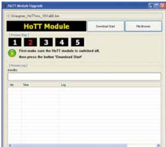
If you have not already done so, switch the transmitter OFF at this point and start the transmitter update procedure by clicking on the "Download Start" button. Wait until the progress bar starts running. This can take up to several seconds. Now switch the transmitter ON with the BIND-Button pressed. After a few seconds, the status display „Found target device ...“ appears. Now release the BIND-Button. The actual update process now commences, and a progress bar starts running:
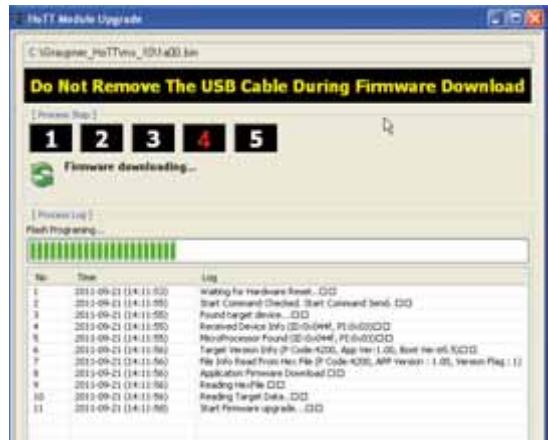
Do not interrupt the update process until the progress bar has reached the right-hand margin, and you see the message "Firmware Download Success" - also a brief buzzer sound appears and the STATUS-LED of the transmitter changes from orange to green:
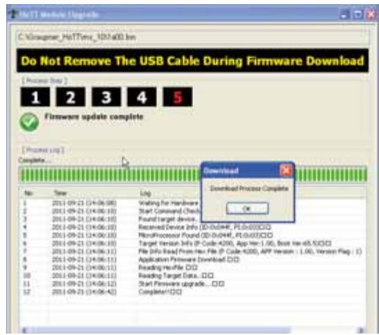
Click on "OK", then switch the transmitter off and finally disconnect the PC or laptop.
If the progress bar does not move forward, close the program and repeat the update procedure, taking note of any error messages which might appear.
4. Initialisation of the transmitter
After a successful update process you MUST - before re-use the transmitter - proceed an initialization for safety reasons:
Press and hold to the BIND-Button on the transmitter and turn it on. Now release the BIND-Button. Except the binding information all other necessary pre-programmed settings in the transmitter are reset to factory settings and must be entered again if needed.
Attention: When initialisation in mode „normal“ is complete, the transmitter will be in Fail-Safe setting mode (page 111), if you do not want to program anything here, turn off the transmitter now.
Using the receiver for the first time
Preliminary notes regarding the GR-12 receiver
Receiving system
The mx-10 HoTT radio control set includes a GR-12 2.4 GHz bi-directional receiver which is suitable for connection to a maximum of six servos.
In order to create a connection to the transmitter, the Graupner HoTT receiver must first be "bound" to "its" model memory in "its" Graupner HoTT transmitter; this procedure is known as "binding". However, binding is only necessary once for each receiver / model memory combination (see pages 106 or 109), and has already been carried out at the factory using the components supplied in the set. You therefore only need to carry out the "binding" process with additional receivers, or if you switch to a different model memory. The procedure can also be repeated whenever you wish - for instance, if you change the transmitter.
For this reason, if you connect the GR-12 HoTT receiver supplied in the set to a power supply and switch it on, the integral LED briefly lights up green, and then goes out again, assuming that "its" transmitter is not in range, or is switched off. If a connection is made, the LED glows a constant green.
Note:
If the LED glows a constant green, but the receiver responds neither to the SET button nor to control commands, then please check the polarity of your receiver power supply.
Receiver voltage display
Once a telemetry connection exists, the actual voltage of the receiver power supply is displayed on the right-hand side of the transmitter screen.
Temperature warning
If the temperature of the receiver falls below a limit value set on the receiver (the default is -10^ ), or exceeds the upper warning threshold, which is also set on the receiver (the default is +70^ ), the transmitter generates a warning in the form of steady beeps at intervals of about one second.
Servo connections and polarity
The servo sockets of Graupner HoTT receivers are numbered. The connector system is polarised: look for the small chamfers when inserting the connectors, and on no account force the plugs into the sockets.
The power supply is through-connected via all the numbered sockets. If there is no vacant servo socket, it is also possible to connect the power supply via a Y-lead, Order No. 3936.11, in parallel with a servo.
Do not connect the battery to these sockets with reversed polarity, as this is likely to ruin the receiver and any devices connected to it.
The function of each individual channel is determined by the transmitter you are using, rather than by the receiver. The throttle servo socket is defined by the radio control system, and may differ according to the make and type. For example, in the case of Graupner radio control systems the throttle function is assigned to channel 1 for fixed-wing models, and channel 6 for helicopters.
Servo socket 5: "SERVO" or "SENSOR"
The servo socket 5, which is marked with an additional "T" ...
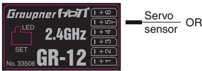
... can be used not only to update the receiver by connecting the adapter lead, Order No. 7168.6A, but also to connect a telemetry sensor.
However, to ensure that the receiver correctly detects the device connected to this socket, servo socket 5 MUST be reset from "SERVO" to "SENSOR" and vice versa to suit the device. This is carried out in the "Te- lemetry" menu on the "RX CURVE" page of the "SET- TING & DATA VIEW" sub-menu. See the section starting on page 120 for more details:
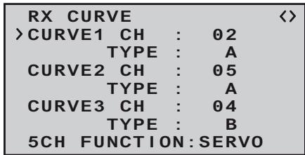
On this menu page locate the “>” symbol at the left-hand edge of the screen, use the INC or DEC button to move it to the bottom line, and then press the INC+DEC button simultaneously:
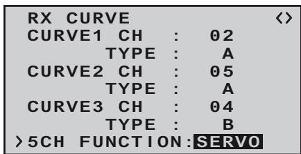
Now select the alternative "SENSOR" setting using one of the INC or DEC buttons:
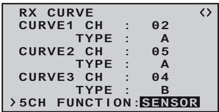
A further press of the NC+DEC buttons concludes your choice.
Concluding notes:
- The much higher servo resolution of the HoTT system results in a substantially more direct response compared with previous technologies. Please take a little time to become accustomed to the finer control characteristics offered by the system!
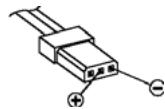
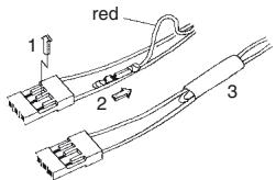
- If you wish to use a speed controller with integral BEC* system in parallel with a separate receiver battery, in most cases (depending on the speed controller) the positive terminal (red wire) must be removed from the three-pin connector, as shown in the diagram. Be sure to read the appropriate notes in the instructions supplied with your speed controller before doing this.
Carefully raise the central lug of the connector slight
ly (1), withdraw the red wire (2) and insulate the bare contact with tape to avoid possible short circuits (3).
Observe the installation notes regarding the receiver, receiver aerial and servos, which you will find on page 96.
Reset
If you wish to carry out a receiver reset, locate the SET button on the top of the receiver and hold it in while you connect its power supply; release the button again.
If the reset is carried out with the transmitter switched off, or if the receiver is not already bound, the receiver LED flashes red slowly after about two or three seconds; at this stage it is immediately possible to initiate a binding process at the transmitter. If the reset is carried out with an already bound receiver, if the transmitter is switched on, and if the associated model memory is active, then the LED lights up green after a short interval to indicate that your transmitter / receiving system is ready for use once more.
Please note the following:
Resetting the receiver resets ALL the settings stored in the receiver to the default settings, with the exception of the binding information! If you carry out a reset by mistake, this means that you will have to restore all the receiver settings entered using the Telemetry menu.
On the other hand, a deliberate RESET is particularly useful if you wish to "re-house" a receiver in a different model, as it represents an easy method of avoiding the transference of unsuitable settings.
Receiver firmware update
Firmware updates for the receiver are carried out using the receiver's telemetry socket - in the case of the GR-12 receiver supplied as standard in the set this is servo socket 5, which is also marked with a "T" - in conjunction with a PC running Windows XP, Vista or 7. To connect the receiver to a PC you require the separately available USB interface, No. 7168.6 and the adapter lead, Order No. 7168.6A. The latter - like all other connecting leads - must always be connected to the GR-12 receiver with the brown or black wire facing up.
The latest software and information can be found in the Download area for the corresponding product at www.graupner.de.
Note:
Once you have registered your transmitter at http://graupner.de/de/service/produktristierung you will automatically be informed of new updates by e-mail as they become available.
Updating the GR-12 software
Attention:
It is essential to check the state of charge of your receiver battery before carrying out any update. To be on the safe side we recommend that you give the battery a full charge.
1. Installing the driver
If you have not already done so, install the driver software for the USB interface, Order No. 7168.6, as described on page 89.
2. Connecting the receiver to the PC
Connect the USB interface, Order No. 7168.6 to the receiver socket marked " -+T" using the adapter lead,
Order No. 7168.6A. The connectors are polarised: look for the small chamfer on the side. The connectors should engage easily; on no account use force. Then connect the USB interface with the USB cable
Adapter cable Order No. 716
(PC-USB/mini-USB) to your PC or laptop. With proper connection the red LED on the interface board lit up for a few seconds. Now turn off the power supply of your receiver.
3. Firmware Update Utility
Start the program "Firmware_Uptage_grStudio_Ver-SX.X.exe" from the appropriate folder by a double-click. (The at the time of printing this manual current version 1.3 starts without prior installation.)

Select "Port Setup" under "Menu"; alternatively open the "Controller Menu" and click on "Port select":
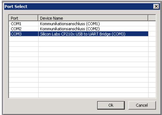
In the "Port select" window you can now select the correct COM port, i.e. the one to which the USB interface is connected. This can be identified by the name "Silicon Labs CP210x USB to UART Bridge" in the "Device Name" column; in the screen-shot above this would be the "COM 3" port.
Now call up the "HoTT Receiver Upgrade option under "Menu", open the "Controller Menu" and click on "HoTT Receiver":
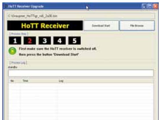
The firmware files are present in a product-specific encoded form, i.e. if you inadvertently select a file which does not match the product (e.g. transmitter update file instead of receiver update file) the pop-up window "Product code error" appears, and the update process cannot be started.
If you have not already done so, switch the receivers power supply OFF at this point and start the receivers update procedure by clicking on the "Download Start" button. Wait until the progress bar starts running. This can take up to several seconds. Now switch the receiver ON with the SET-Button pressed. After a few seconds, the status display „Found target device ...“ appears. Now release the SET-Button. The actual update process now commences, and a progress bar starts running:
On the other hand, if the device is not recognised, the pop-up window "Target device ID not found" appears.
If the process is interrupted before the progress bar reaches the 100% mark, switch off your receiver power supply and carry out another attempt at the update process, i.e. repeat all the steps described above.
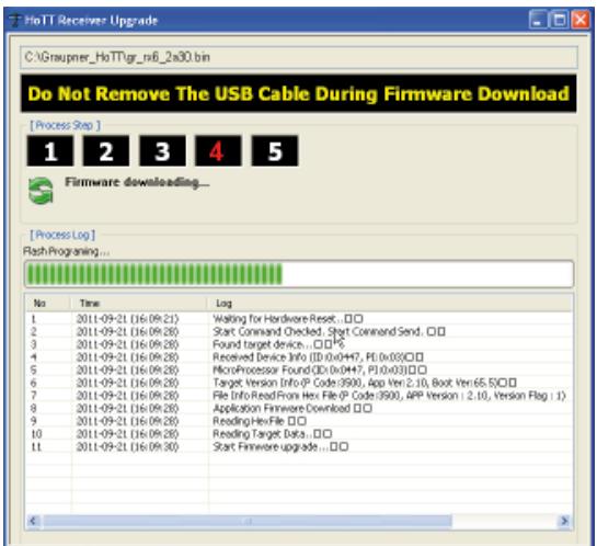
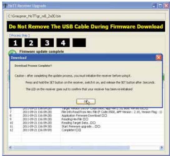
The Status Display and the progress bar show the progress of the firmware update process. The update is completed when the message "Download Process Complete!!" appears.
During the update process the green LED on the receiver light up. When the update is completed, the green LED goes out.
Switch the receiver off, and disconnect the interface lead. If you have multiple receivers, you must repeat the procedure with each one.
4. Initialising the receiver
Once you have completed the update process, for safety reasons you MUST initialise the receiver before
re using it again:
Hold the SET button on the receiver pressed in while you switch on its power supply; then release the SET button again after approx. 3 sec - the green LED expires. If you now switch the transmitter on again, after about two or three seconds the green LED on the receiver will light up constantly. However, all the other previously programmed settings in the receiver - with the exception of the binding information - are now reset to the factory default values, and you will need to re-enter them if required.
Installation Notes
Installing the receiver
Regardless of which Graupner receiving system you are using, the procedure is always the same:
Please note that the receiver aerials must be arranged at least 5cm away from all large metal parts and leads which are not attached or connected directly to the receiver. This includes steel and carbon fibre components, servos, fuel pumps, cables of all sorts, etc. Ideally the receiver should be installed in an easily accessible position in the model, away from all other installed components. Under no circumstances run servo leads immediately adjacent to the receiver aerials, far less coil them round it!
Tests have shown that a vertical (upright) position of a single aerial produces the best results when long approaches are flown with a model. If the receiver features a diversity aerial system (two aerials), the second aerial should be deployed at an angle of 90^ to the first.
The servo sockets of Graupner receivers are numbered. The power supply is through-connected via all the numbered sockets, and in principle can be connected to any of the servo sockets. It is also possible to connect the power supply via a Y-lead, Order No. 3936.11, in parallel with a servo.
The following section contains notes and helpful ideas on installing radio control components in the model:
- Wrap the receiver in foam rubber at least 6 mm thick. Fix the foam round the receiver using rubber bands, to protect it from vibration, hard landings and crash damage.
- All switches must be installed in a position where they will not be affected by exhaust gases or vibrati
on. The switch toggle must be free to move over its full range of travel.
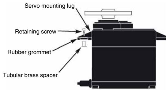
- Always install servos using the vibration-damping grommets and tubular metal spacers supplied. The rubber grommets provide some degree of protection from mechanical shock and severe vibration. Don't over-tighten the servo retaining screws, as this will compress the grommets and thereby reduce the vibration protection they afford. The system offers good security and vibration protection for your servos, but only if the servo retaining screws are fitted and tightened properly. The drawing below shows how to install a servo correctly. The brass spacers should be pushed into the rubber grommets from the underside.
- The servo output arms must be free to move over their full arc of travel. Ensure that no parts of the mechanical linkage can obstruct the servo's movement.
The sequence in which the servos are connected to the receiver is dictated by the model type. Please see the socket assignments listed on pages 43 and 47.
Be sure to read the additional safety notes on pages 3 ... 9.
If the receiver is ever switched on when the transmitter is off, the servos may carry out uncontrolled movements. You can avoid this by switching the system on in this
order:
Always switch the transmitter on first, then the receiver.
When switching the system off:
Always switch the receiver off first, then the transmitter.
When programming the transmitter you must always ensure that any electric motors in the system cannot possibly burst into life accidentally, and that an I.C. engine fitted with an automatic starter cannot start unintentionally. In the interests of safety it is always best to disconnect the flight battery, or cut off the fuel supply.
Receiving system power supply
A reliable power supply is one of the basic essentials for reliable model control. Free-moving pushrods, a fully-charged battery, battery connecting leads of adequate cross-section, minimal transfer resistance at the connectors etc. all help to minimise energy consumption, but if you have attended to all this, and the receiver voltage displayed on the transmitter screen still collapses repeatedly, or is generally (too) low, then please note the following:
The first point to check is that your batteries are always fully charged at the start of each flying session. Check that contacts and switches are low in resistance. It is a good idea to measure the voltage drop over the installed switch harness under load, as even a new, heavy-duty switch can cause a voltage drop of up to 0.2 Volt. Ageing effects and oxidation of the contacts can increase this several times over. Constant vibration and movement at the contacts also "gnaws away" at the contacts, and tends to produce a creeping increase in transfer resistance.
It is also true that even small servos, such as the Graupner/JR DS-281, can draw currents of up to 0.75 Ampere when stalled (mechanically obstructed). Just four servos of this type in a "foamy" can therefore place a load of up to 3 Amps on the airborne power supply ...
For this reason you should always choose a receiver battery which constantly delivers an adequate voltage, i.e. which does not collapse under severe load. To "calculate" the necessary battery capacity we recommend as a starting point that you provide 350 mAh for each analogue servo, and at least 500 mAh for each digital servo.
For example, a 1400 mAh battery would represent an absolute minimum as the power supply for a receiving
system with a total of four analogue servos. When making your calculations, however, please bear the receiver in mind as well, as it draws a current of around 70 mA due to its bi-directional function.
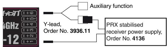
Regardless of these considerations, it is generally advisable to connect the power supply to the receiver using two leads. For example, you could use a switch or voltage regulator with two power supply leads running to the receiver. You might install a Y-lead, Order No. 3936.11, between lead and receiver, as shown in the diagram below, if you wish to use one or both of the receiver sockets to connect a servo, speed controller, etc. The dual connection at the switch or voltage regulator not only reduces the risk of a cable fracture, but also ensures a more even energy supply to the servos connected to the receiver.
Four-cell Ni-MH battery packs
Traditional four-cell packs are a good choice for powering your Graupner HoTT receiving system, provided that you observe the conditions described above, i.e. you must ensure that the packs have adequate capacity and maintain their voltage well.
Five-cell NiMH battery packs
Five-cell batteries offer a wider margin of safety in terms of voltage compared with four-cell packs. However, please note that not all servos available on the market can tolerate the voltage of a five-cell pack (in the long-term), especially when the battery is freshly charged.
For example, many of these servos respond to the high voltage with a clearly audible "rumble".
It is therefore important to check the specification of the servos you intend to use before you make the decision to use five-cell packs.
Two-cell Nanophosphate® (A123) batteries
Taking into account the current situation, these new cells are now regarded as the optimum choice for receiver packs. A123 cells can be fast-charged in conjunction with a suitable battery charger, and are protected by a metal case and therefore comparatively robust. It is also true that a much higher number of charge / discharge cycles is attributed to this cell type than, for example, to LiPo cells. The nominal voltage of 6.6 Volt of a two-cell Nanophosphate® pack presents no problems to Graupner HoTT receivers, nor to those servos, speed controllers, gyros, etc. which are expressly approved for use at these higher voltages. Please note, however, that virtually all servos, speed controllers, gyros etc. sold in the past, and also most of those currently available, are only approved for use on an operating voltage in the range 4.8 to 6 Volt. If you wish to connect these devices to the receiver, it is essential to use a stabilised regulated power supply, such as the PRX, Order No. 4136; see Appendix. If you neglect this, there is a danger that the connected devices will quickly suffer permanent damage
Two-cell LiPo battery packs
For a given capacity LiPo batteries are a great deal lighter than the battery types described above, but they are more susceptible to mechanical stress and damage due to their lack of a metal case. Moreover LiPo batteries only have a limited ability to be fast-charged, and
generally do not survive such a high number of charge / discharge cycles as is claimed for other batteries, such as Nanophosphate® types. The comparatively high nominal voltage of 7.4 Volt of a two-cell LiPo pack presents no problems to Graupner HoTT receivers, nor to those servos, speed controllers, gyros, etc. which are expressly approved for use at these higher voltages. Please note, however, that virtually all servos, speed controllers, gyros etc. sold in the past, and also most of those currently available, are only approved for use on an operating voltage in the range 4.8 to 6 Volt. If you wish to connect these devices to the receiver, it is essential to use a stabilised regulated power supply, such as the PRX, Order No. 4136; see Appendix. If you neglect this, there is a danger that the connected devices will quickly suffer permanent damage.
Definition of terms
Control functions, transmitter controls, function inputs, control channels, mixers, switches, control switches, Smart-Box
To make it easier for you to understand the mx-10 HoTT manual, the following section contains definitions of many terms which crop up again and again in the remainder of the text.
Control function
The term "control function" can be thought of as the signal generated for a particular function which needs to be controlled - initially independent of its subsequent progress through the transmitter. In the case of fixed-wing model aircraft the control functions include throttle, rudder and aileron, whereas collective pitch, roll and pitch-axis are typical of those used for helicopters. The signal of a control function may be assigned directly, or to several control channels simultaneously via mixers. A typical example of the latter is separate aileron servos or a V-Tail. The essential feature of a control function is its influence on the mechanical travel of the corresponding servo.
Transmitter control
The term "transmitter control" refers to the mechanical elements on the transmitter which are operated directly by the pilot. Their movements in turn generate corresponding movements in the servos, speed controllers etc. at the receiver end. The transmitter controls include the following:
- The two dual-axis stick units for the control functions 1 to 4; for both model types ("fixed-wing" and "helicopter") these four functions can be interchanged in any way you wish using the "Mode" function, e.g. throttle left or right, without having to re-connect the servos. The dual-axis stick function for throttle (or airbrakes) is often referred to as the Ch 1 (Channel 1) control.
- The switch for channel 5 When a proportional transmitter control is operated,
the servo or servos follow the position of the control directly, whereas a switched channel provides just the two or three set servo positions.
This is an imaginary point on the signal path, and must not be considered the same as the point on the circuit board where the transmitter control is connected! The two menus "Stick mode" and "Transmitter control settings" affect the course of the signal "after" this point, and it is possible (and likely) that there will be differences between the number of the transmitter control (as stated above) and the number of the subsequent control channel.
Control channel
There is a point on the signal path where the signal contains all the control information required for a particular servo – this may be directly generated by a transmitter control or indirectly via a mixer – and from this point on we call the signal a “control channel”. This signal is only affected by any adjustments carried out in the “Servo settings” menu before leaving the transmitter via the RF module. Once picked up at the receiver, this signal may be modified by any settings made in the Telemetry menu before finally passing to the corresponding servo in the model.
Mixer
The transmitter's software includes a wide range of mixer functions. Their purpose is to enable a control function to affect multiple servos at the branching point of the mixer input, or alternatively to allow several control functions to affect one servo. For more information please refer to the numerous mixer functions of the Smart-Box as described on page 119 of the manual.
Switch
The standard toggle switch for channel 5 moves the connected servo to the min./max. position.
Smart Box
The optional Smart-Box allows the use of many other HoTT functions such as:
- transmitter voltage display with programmable warning threshold
- Receiver Temperature
Servo travel
- Channel Mapping
- Mixer settings
- Signal quality
- Receiver Voltage
Servo neutral position
- Cycle time
- Channel-dependent fail-safe settings
Servo test
see the section ,telemetry" on page 113.
More details of the Smart-Box you will find the Graupner catalog FS and online under www.graupner.de/en
Digital trims and stick calibration
Description of function
Digital trims with visual and audible indicators
Both the dual-axis stick units are fitted with digital trim systems. When you give the trim lever a brief push (one "click"), the neutral position of the associated stick channel changes by one increment. If you hold the trim lever in one direction, the trim value changes continuously in the corresponding direction with increasing speed.
The degree of trim offset is also "audible", as the pitch of the tone changes to reflect the setting. When you are flying a model, you can find the trim centre position easily without having to look at the screen: if you over-run the centre setting, the trim stays in the centre position for a moment.
The current trim values are automatically stored.
The digital trim only works when the transmitter is switched ON. When switched OFF, even an accidental touch of the trim lever does not change the set values.
Stick Calibration
If you suspect that the centre point of your self-centring sticks (transmitter controls 1 ... 4) does not correspond exactly to 0% travel of the transmitter control, you can check and - if necessary - correct it using the following procedure:
Turn OFF the transmitter, and insert the supplied programming plug into the DATA jack on the back and the jumper in position „DELTA“ on the front of the transmitter. Bring both sticks in the middle position. Turn the radio ON. The transmitter starts beeping after one second for 10 seconds once per second. During this 10 seconds move both control sticks to all the end positions, so that the transmitter can save this positions. After expiration of the 10 seconds the calibration is completed and the transmitter is back in the normal mode, the beeps become silent. Turn the transmitter off and then remove the programming plug on the back.
Do not use the remote control with programming connector plugged in!
If necessary, plug the jumper into the correct position for your model.
If you have achieved not all stick-end positions during these 10 seconds, repeat the entire process.
This program provides convenient support for normal model aircraft with up to two aileron servos, V-tail models, flying wings and deltas with two elevon (aileron / elevator) servos.
The majority of power models and gliders belong to the "normal" tail type with one servo each for elevator, rudder, ailerons and throttle or electronic speed controller (airbrakes on a glider).
If your model features two separate aileron servos (and also in some cases two flap servos), the aileron travel of both pairs of control surfaces can be set up with differential movement in the "Tail type" menu.
If the model features a V-tail instead of a conventional tail, you need to select the tail type "V-tail" with in the "Tail type" menu, as this automatically superimposes the elevator and rudder control functions in such a way that each tail panel can be actuated by a separate servo. For deltas and flying wings it is easy to set up mixed elevons, i.e. the aileron and elevator functions can be carried out via common control surfaces at the trailing
edge of the right and left wing. As standard the program contains the appropriate mixer functions for the two servos.
More functions are programmable with the optional Smart Box. See the section „Telemetry“ on page 113.
Pre-installed "wing mixers" of the mx-10 HoTT
- No mixer Tail type „normal"
- Mixer AILERON 2 Ailerons
- Mixer DELTA Flying wings
- Mixer V-Tail V-Tail
See the pictures below on this page.
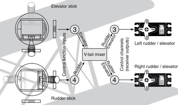
Example: V-tail mixer
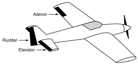
Tail type „normal“
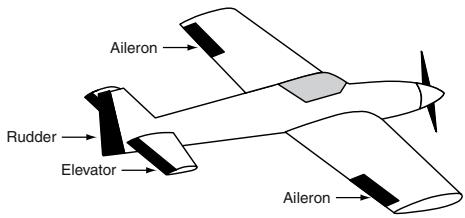
Mixer AILE ,2 Aileron"
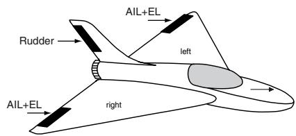
Mixer DELTA „Flying wings"
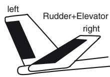
Mixer ,V-Tail"
Installation notes
The servos MUST be connected to the receiver outputs in the following order:
Outputs not required are simply left vacant.
Please note the following points in particular:
- If you are using only one aileron servo, receiver output 5 (right aileron) is left unused; it can also be used for another purpose if you select "1 AIL" in the "Basic settings" menu.
- Please also read the information on the following pages.
Powered and unpowered fixed-wing model aircraft, with up to two ailerons ...
... and "normal" tail type
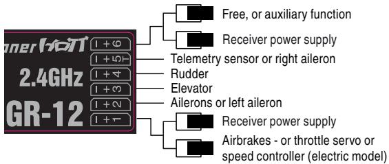
... and "V-tail" tail type
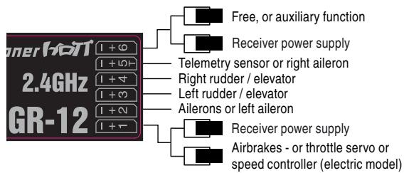
... and "2 elevator servos" tail type - only with optional Smart-Box
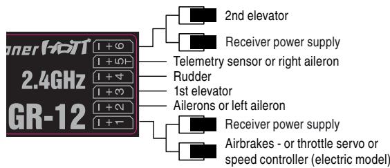
Powered and unpowered delta / flying wing models
... with two elevon and two elevator servos
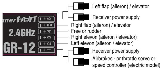
As there are several possible combinations of servo orientation and control surface linkage, you may find that the direction of rotation of one or more servos is incorrect. Use the following table to solve the problem.
| Model type | Servo rotating in wrong direction | Remedy |
| V-tail | Rudder and elevator reversed | Reverse servos 3 + 4 in the “servo set.” menu |
| Rudder correct, elevator reversed | Swap over servos 3 + 4 at the receiver |
| Elevator correct, rudder reversed | Reverse servos 3 + 4 in the “servo set.” menu, AND swap over at the receiver |
| Delta, flying wing | Elevator and ailerons reversed | Reverse servos 2 + 3 in the “servo set.” menu |
| Elevator correct, ailerons reversed | Reverse servos 2 + 3 in the “servo set.” menu, AND swap over at the receiver |
| Ailerons correct, elevator reversed | Swap over servos 2 + 3 at the receiver |
All menus which are relevant to fixed-wing models are marked with an "aeroplane" symbol in the "Program descriptions":

This means that you can easily skip irrelevant menus when programming a fixed-wing model aircraft.

Model helicopters
The continued development of model helicopters and helicopter components, such as gyros, speed governors, rotor blades etc., has led to the current position where helicopters are capable of sophisticated 3-D aerobatics.
Model helicopters can be operated with the mx-10 HoTT only with stabilizer-free systems „flybarless“, for example V-Stabi or Microbeast be operated. This system mixes it all for the swashplate and tail rotor necessary servos.
The motor is controlled by switching channel 5. For the connection of the servos for your flybarless system refer to the related manual. If the telemetry function of the receiver is used, the motor control must be switched to channel 6 using the optional Smart Box (see page 117 channel mapping) in order to connect the telemetry sensors on channel 5.
All menus which are relevant to model helicopters are marked with a "helicopter" symbol in the "Program descriptions":

This means that you can easily skip irrelevant menus when programming a model helicopter.
Installation notes
The servos will be connected to the receiver outputs in the order shown on this page:
Outputs not required are simply left vacant.
Please note the additional information of your flybarless system.
Receiver assignment for model helicopters ...
... with flybarless system
free or throttle (Channel Mapping with optional Smart-Box)
Telemetry sensor or throttle
Tail rotor servo (Gyro system)
Pitch servo
Roll servo
Pitch- or Roll-2 servo
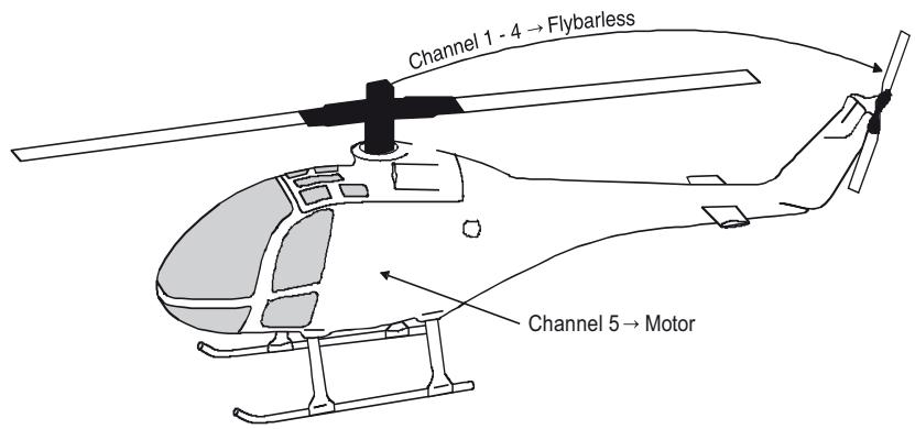
Before you start programming specific parameters, some basic settings must be entered.
Stick mode
| “MODE 1” (Throttle at right stick) | “MODE 2” (Throttle at left stick) |
| elev. down | full throttle | full throttle | elev. down |
| left rudder | right rudder | right rudder | right aleron |
| elev. up | idle | idle | elev. up |
| “MODE 3” (Throttle at right stick) | “MODE 4” (Throttle at left stick) |
| elev. down | Motor Volgas | full throttle | elev. down |
| left aleron | left aleron | left aleron | right aleron |
| elev. up | idle | idle | elev. up |
Basically there are four possible ways of arranging the principal control functions of a fixed-wing model on the two dual-axis sticks: the primary functions are aileron, elevator, rudder and throttle (or airbrakes). Which of these options you select depends on your individual preferences and flying style.
To select the stick mode, first select the transmitter mode „normal“ with the mode switch. Turn the transmitter OFF and insert the supplied programming plug into the DATA socket on the back of the transmitter. Turn ON the transmitter: you can now call up the desired stick mode by cycling through the modes with a brief press of the BIND-button:
| Buzzer | LED | Description |
| transmitter buzzers 1x | orange LED on | Country setting Universal/Europe |
| transmitter buzzers 2 times | orange LED flashes | County setting France |
| The country setting is described in detail below. |
| transmitter buzzers 3 times | orange LED on | »MODE 1« |
| transmitter buzzers 4 times | orange LED on | »MODE 2« |
| transmitter buzzers 5 times | orange LED on | »MODE 3« |
| transmitter buzzers 6 times | orange LED on | »MODE 4« |
To choose a mode, hold the BIND-button pressed for approx. three seconds. When you release the button, the transmitter should emit an audible signal and the buzzer sound stops. Switch OFF the transmitter and remove the programming plug.
Never use the remote control with programming connector plugged in!
Later, to check the stick mode which is programmed, watch out for the Status-LED on the transmitter.
Stick mode
After you have set the stick mode, the country setting must be done in a second step.
The Country setting is present in order to cater for various directives (FCC, ETSI, IC etc.). The HoTT 2.4 radio system features a restricted frequency band for France.
If you wish to use the RC system in France, the country setting on the transmitter must be set to "France" mode, as described. It is essential not to use the Universal/EUROPE mode.
To select a Country setting, you must first switch the transmitter off, then insert the supplied programming plug in the DATA socket on the back and the Jumper in the position „NO MIX“ on the front of the transmitter. Switch the transmitter on: you can now toggle between the “GENERAL” and “France” settings by briefly pressing the BIND-button:
| Buzzer | LED | Description |
| transmitter buzzers 1x | orange LED on Universal/Europe | |
| transmitter buzzers 2 times | orange LED flashes | County setting France |
To choose a country, hold the BIND-button pressed for approx. three seconds. When you release the button, the transmitter should emit an audible signal and the buzzer sound stops. Switch OFF the transmitter and remove the programming plug.
Never use the remote control with programming connector plugged in!
Later, to check the country setting which is programmed, watch out for the Status-LED on the transmitter.
Notes:
- During the programming process it is important to ensure that any internal-combustion engine or electric motor cannot start running accidentally. The safe option is always to disconnect the fuel supply or the flight battery.
Tail type
The tail configuration is chosen with the supplied jumper in the contact strip „MIX“ on the front of the transmitter. Select the positioning of the jumpers to match your model type
,normal": The elevator and rudder is operated by only one servo.
The jumper connects the two middle pins _NO MIX".
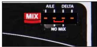
2Aileron:
This option is for models with 1 or 2 ailerons. The at the channel 5 connected servo runs parallel to the servo on channel 2 The Aileron trim affects both servos. The jumper connects the two left pins "AILE".
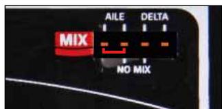
Delta/FW: The aileron and elevator rudder is controlled by one servo per wing half, connected on channel 2 and 3. The coupling function for the aileron and elevator control is performed automatically by the transmitter mixer.
The jumper connects the two right pins "DELTA".
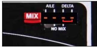
"V-Tail": The elevator and rudder functions are operated by two control surfaces set in a V-shape, each controlled by a separate servo, connected to channel 2 and 3. The two-way coupling function for the rudder and elevator control systems is automatically carried out by the transmitter software.
Two jumpers connect the two left "AILE" and two right "DELTA" pins.
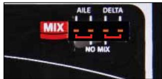
Due to the different installation of the servos and push-rods the initially servo direction of certain servos may be wrong. The following table provides guidance for remedial action.
| Model type | Servo with wrong rotating direction | Solution |
| V-Tail | Rudder and elevator wrong direction | servo reverse for channel 3 + 4 in the bar „Servo reverse“ |
| Rudder correct, elevator wrong direction | change servo 3 + 4 at the receiver |
| Elevator correct, rudder wrong direction | servo reverse for channel 3 + 4 in the bar „Servo reverse“ AND change at the receiver |
| Delta, Flying wing | Elevator and Ail wrong direction | servo reverse for channel 2 + 3 in the bar „Servo reverse“ |
| Elevator correct, Ail wrong direction | servo reverse for channel 2 + 3 in the bar „Servo reverse“ AND change at the receiver |
| Ail correct, Elevator wrong direction | change servo 2 + 3 at the receiver |
Receiver output
For maximum flexibility in terms of receiver socket assignment, the optional Smart-Box provides the means to swap over the servo outputs 1 to max. 6 - „channel mapping“, see also chapter „telemetry“ on page 113.
With the Channel mapping function of the Smart-Box the six control functions of the mx-10 HoTT transmitter can be shared out between several receivers if necessary, or alternatively several receiver outputs can be assigned to the same control function; for example, you may wish to be able to operate each aileron with two servos, or to control an oversized rudder using two coupled servos instead of a single one.
rx bind
Graupner HoTT receivers have to be "instructed" to communicate exclusively with a particular model (i.e. model memory) of a Graupner HoTT transmitter. This process is known as "binding", and is only necessary once for each new combination of receiver and model. It can be repeated at any time.
Important note:
When carrying out the binding procedure, please ensure that the transmitter aerial is always an adequate distance from the receiver aerials: keeping the aerials about 1m apart is safe in this respect. Otherwise you risk a failed connection to the downlink channel, and consequent malfunctions.
"Binding" multiple receivers to one model
If necessary, it is possible to bind more than one receiver to a single model. This is accomplished by initially binding the receivers individually, as described in the next section. When operating the system, please note that only the receiver which was bound last will establish a telemetry link to the transmitter. For this reason all telemetry sensors installed in the model must be connected to this receiver, since only the last bound receiver is able to transmit their data via the down-link channel. The second, and all other receivers, run in parallel to the receiver last bound to the transmitter, but completely independently of it; they operate in Slave mode with the down-link channel switched off.
If a receiver is switched ON which does not transmit telemetry, the Status-LED changes from orange to green.
"Binding" transmitter and receiver
Note: The mx-10 HoTT can be bound in the mode „normal“ only. Make sure before you start the binding process, that the transmitter is programmed in this mode. See page 88 for mode setting.
Turn the transmitter ON and then power up your receiver: At the receiver, the green LED flashes once briefly, and then goes out.
The LED on the transmitter lights up green to show that no bound receiver is connected.
Press and hold the SET button on the receiver until the green LED starts to flash.
Briefly press the BIND-button of the transmitter to initiate the so-called binding process.
If the receiver LED glows a constant green within about ten seconds, then the binding process has been completed successfully; you can now release the receiver's SET button.
Your model / receiver combination is now ready for use. In parallel with this the Status-LED switches from green to orange:
Conversely, if the green LED on the receiver flashes for longer than about ten seconds or the transmitters Status-LED remains green, then the binding process has failed. If this should occur, alter the relative position of the aerials, and repeat the whole procedure.
range test
The integral range-check reduces the transmitter's output power in such a way that you can test the system's operation at a distance of up to about fifty metres.
Carry out the range-check of the Graupner HoTT system in accordance with the following instructions. We
recommend that you ask a friend to help with range-checking.
- Install the receiver in the model as required, preferably after completing the binding process with the transmitter.
- Switch the radio control system on and wait until the green LED on the receiver glows. Now you can observe the servo movements.
- Place the model on a flat surface (paving, close-mown grass or earth), with the receiver aerials at least 15cm above the ground. This means that you may have to place the model on a raised object for the period of the check.
- Hold the transmitter at hip-height, and away from your body. However, do not point the aerial straight at the model; instead rotate and / or angle the tip of the aerial so that it is vertical while you carry out the check.
- Make sure that the transmitter in the "normal" mode - mode switch to the rear. Now press the BIND-button for about 5 s, until the transmitter starts to beep permanently. Disengage the BIND-button again. Note when using multiple receivers for each model: the range test only works with the receiver which transmits the telemetry signal - that is the last bound receiver.
- When you start the range-check, the transmitter's output power is significantly reduced, at the same time a permanent beep sounds. When the 99 seconds of the range-check period have elapsed, the transmitter switches back to full power, and the beep sound stops. Note: you can stop the range test at any time by pressing again the BIND button.
- Within this period walk away from the model, moving the sticks all the while. If at any point within a distance
of about fifty metres you notice a break in the connection, attempt to reproduce it.
- If the model is fitted with a motor, switch it on in order to check the system's interference rejection.
- Walk further away from the model until you no longer have full control over it.
- At this point wait until the test period has elapsed, with the model still switched on and ready for use. When the range-check period is over, the model should respond again to control commands. It is not 100% the case, do not use the system. Contact your nearest Service Centre of Graupner GmbH & Co. KG.
- Carry out the range-check before every flight, and simulate all the servo movements which are likely to occur in a typical flight. To ensure safe operation of the model, the range must always be at least fifty metres on the ground.
Caution:
Never initiate a range-check when you are actually operating a model!
Before you start programming specific parameters, some basic settings must be entered which apply only to the currently active model memory.
Stick mode
| “MODE 1” (Throttle at right stick) | “MODE 2” (Throttle at left stick) |
| pitch axis | throttle | throttle | pitch axis |
| roll | roll | tail rotor | roll |
| pitch axis | throttle | throttle | pitch axis |
| “MODE 3” (Throttle at right stick) | “MODE 4” (Throttle at left stick) |
| pitch axis | Motor/Pitch | throttle | pitch axis |
| roll | roll | tail rotor | tail rotor |
| pitch axis | throttle | throttle | pitch axis |
Basically there are four possible ways of arranging the principal control functions of a model helicopter on the two dual-axis sticks: the primary functions are roll, pitch-axis, tail rotor and throttle / collective pitch. Which of these options you select depends on your individual preferences and flying style:
To select the stick mode, first select the transmitter mode „normal“ with the mode switch. Turn the transmitter OFF and insert the supplied programming plug into the DATA socket on the back of the transmitter. Turn ON the transmitter: you can now call up the desired stick mode by cycling through the modes with a brief press of the BIND-button:
| Buzzer | LED | Description |
| transmitter buzzers 1x | orange LED on | Country setting Universal/Europe |
| transmitter buzzers 2 times | orange LED flashes | County setting France |
| The country setting is described in detail below. |
| transmitter buzzers 3 times | orange LED on | »MODE 1« |
| transmitter buzzers 4 times | orange LED on | »MODE 2« |
| transmitter buzzers 5 times | orange LED on | »MODE 3« |
| transmitter buzzers 6 times | orange LED on | »MODE 4« |
To choose a mode, hold the BIND-button pressed for approx. three seconds. When you release the button, the transmitter should emit an audible signal and the buzzer sound stops. Switch OFF the transmitter and remove the programming plug.
Never use the remote control with programming connector plugged in!
Later, to check the stick mode which is programmed, watch out for the Status-LED on the transmitter.
Country setting
After you have set the stick mode, the country setting must be done in a second step.
The Country setting is present in order to cater for various directives (FCC, ETSI, IC etc.). The HoTT 2.4 radio system features a restricted frequency band for France.
If you wish to use the RC system in France, the country setting on the transmitter must be set to "France" mode, as described. It is essential not to use the Universal/EUROPE mode.
To select a Country setting, you must first switch the transmitter off, then insert the supplied programming plug in the DATA socket on the back and the Jumper in the position „NO MIX“ on the front of the transmitter. Switch the transmitter on: you can now toggle between the “GENERAL” and “France” settings by briefly pressing the BIND-button:
| Buzzer | LED | Description |
| transmitter buzzers 1x | orange LED on Universal/Europe | |
| transmitter buzzers 2 times | orange LED flashes | County setting France |
To choose a country, hold the BIND-button pressed for approx. three seconds. When you release the button, the transmitter should emit an audible signal and the buzzer sound stops. Switch OFF the transmitter and remove the programming plug.
Never use the remote control with programming connector plugged in!
Later, to check the country setting which is programmed, watch out for the Status-LED on the transmitter.
Notes:
- During the programming process it is important to ensure that any internal-combustion engine or electric motor cannot start running accidentally. The safe option is always to disconnect the fuel supply or the flight battery.
Flybarless systems
Connect your Flybarless system on the channels 1 - 4 at the receiver to match your Helicopter type. Please refer to the instructions of your system.
Receiver output
For maximum flexibility in terms of receiver socket assignment, the optional Smart-Box provides the means to swap over the servo outputs 1 to max. 6 - „channel mapping“, see also chapter „telemetry“ on page 113.
With the Channel mapping function of the Smart-Box the six control functions of the mx-10 HoTT transmitter can be shared out between several receivers if necessary, or alternatively several receiver outputs can be assigned to the same control function; for example, you may wish to be able to operate each aileron with two servos, or to control an oversized rudder using two coupled servos instead of a single one.
rx bind
Graupner HoTT receivers have to be "instructed" to communicate exclusively with a particular model (i.e. model memory) of a Graupner HoTT transmitter. This process is known as "binding", and is only necessary once for each new combination of receiver and model. It can be repeated at any time.
Important note:
When carrying out the binding procedure, please ensure that the transmitter aerial is always an adequate distance from the receiver aerials: keeping the aerials about 1m apart is safe in this respect. Otherwise you risk a failed connection to the downlink channel, and consequent malfunctions.
"Binding" multiple receivers to one model
If necessary, it is possible to bind more than one receiver to a single model. This is accomplished by initially binding the receivers individually, as described in the next section. When operating the system, please note that only the receiver which was bound last will establish a telemetry link to the transmitter. For this reason all telemetry sensors installed in the model must be connected to this receiver, since only the last bound receiver is able to transmit their data via the down-link channel. The second, and all other receivers, run in parallel to the receiver last bound to the transmitter, but completely independently of it; they operate in Slave mode with the down-link channel switched off.
If a receiver is switched ON which does not transmit telemetry, the Status-LED changes from orange to green.
"Binding" transmitter and receiver
Note: The mx-10 HoTT can be bound in the mode „normal“ only. Make sure before you start the binding process, that the transmitter is programmed in this mode. See page 88 for mode setting.
Turn the transmitter ON and then power up your receiver: At the receiver, the green LED flashes once briefly, and then goes out.
The LED on the transmitter lights up green to show that no bound receiver is connected.
Press and hold the SET button on the receiver until the green LED starts to flash.
Briefly press the BIND-button of the transmitter to initiate the so-called binding process.
If the receiver LED glows a constant green within about ten seconds, then the binding process has been completed successfully; you can now release the receiver's SET button.
Your model / receiver combination is now ready for use. In parallel with this the Status-LED switches from green to orange:
Conversely, if the green LED on the receiver flashes for longer than about ten seconds or the transmitters Status-LED remains green, then the binding process has failed. If this should occur, alter the relative position of the aerials, and repeat the whole procedure.
range test
The integral range-check reduces the transmitter's output power in such a way that you can test the system's operation at a distance of up to about fifty metres.
Carry out the range-check of the Graupner HoTT system in accordance with the following instructions. We
recommend that you ask a friend to help with range-checking.
- Install the receiver in the model as required, preferably after completing the binding process with the transmitter.
- Switch the radio control system on and wait until the green LED on the receiver glows. Now you can observe the servo movements.
- Place the model on a flat surface (paving, close-mown grass or earth), with the receiver aerials at least 15 cm above the ground. This means that you may have to place the model on a raised object for the period of the check.
- Hold the transmitter at hip-height, and away from your body. However, do not point the aerial straight at the model; instead rotate and / or angle the tip of the aerial so that it is vertical while you carry out the check.
- Make sure that the transmitter in the „normal“ mode - mode switch to the rear. Now press the BIND-button for about 5 s, until the transmitter starts to beep permanently. Disengage the BIND-button again. Note when using multiple receivers for each model: the range test only works with the receiver which transmits the telemetry signal - that is the last bound receiver.
- When you start the range-check, the transmitter's output power is significantly reduced, at the same time a permanent beep sounds. When the 99 seconds of the range-check period have elapsed, the transmitter switches back to full power, and the beep sound stops. Note: you can stop the range test at any time by pressing again the BIND button.
- Within this period walk away from the model, moving the sticks all the while. If at any point within a distance
of about fifty metres you notice a break in the connection, attempt to reproduce it.
- If the model is fitted with a motor, switch it on in order to check the system's interference rejection.
- Walk further away from the model until you no longer have full control over it.
- At this point wait until the test period has elapsed, with the model still switched on and ready for use. When the range-check period is over, the model should respond again to control commands. It this is not 100% the case, do not use the system. Contact your nearest Service Centre of Graupner GmbH & Co. KG.
- Carry out the range-check before every flight, and simulate all the servo movements which are likely to occur in a typical flight. To ensure safe operation of the model, the range must always be at least fifty metres on the ground.
Caution:
Never initiate a range-check when you are actually operating a model!
The mx-10 HoTT can adjust the servo direction and servo travel - dual rate.
Servo rotating direction
The direction of servo rotation can be adjusted to suit the actual installation in your model. This means that you don't need to concern yourself with servo directions when installing the mechanical linkages in the model, as you can reverse them as and when necessary. The rotation direction is set individually for each channel with the servo reverse - switches on the front of the transmitter. The direction is symbolized by „NOR“ for normal rotation and „REV“ to reverse the direction of rotation.
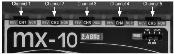
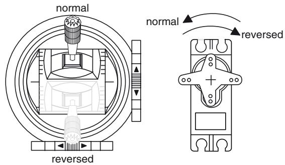
Servo travel „Dual Rate“
To adjust servo travel symmetrically, i.e. to adjust travel equally on both sides of neutral for elevator, rudder and aileron. The adjustment range is fixed and can be selected between 70% (switch in lower position) and 100% (switch in upper position) of servo travel.
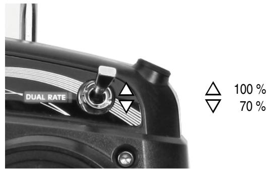
Note:
With the optional Smart-Box the servo travel can be programmed separately and also asymmetrically for all channels. See the section "telemetry" on page 113.
Fail Safe
In its default state (as delivered) the receiver is set to Hold" mode, i.e. if a fail-safe situation occurs, all the servos connected to it maintain the last position detected as valid. In this mode the green LED on the receiver expires when interference occurs, and the orange LED on the transmitter starts flashing 3-times for a short period. In addition the transmitter also starts beeping in the same way like the Status-LED as an audible warning. You can exploit the safety potential of the fail-safe option by at least programming the throttle channel to respond to a fail-safe situation: the throttle channel of an engine-powered model should be set to idle, the throttle channel of an electric-powered model to "stop", and the throttle channel of a model helicopter to "Hold". If interference should occur, these settings will help prevent the model flying out of control, possibly causing personal injury or property damage.
IMPORTANT:
The two functions "Binding" and "Range check" described above can be used regardless of the method you last employed to program the transmitter, i.e. using the programming button or the SMART-BOX; neither of these two options causes significant changes to the settings saved in the receiver. However, if you call up the Fail-Safe function using the programming button as described below, this resets ALL the settings of the SMART-BOX at the Fail-Safe screen (RX FAIL SAFE) - and this includes the settings available through the facilities of the programming button. At the same time the Country setting will revert to Universal if you have previously selected "France" using the programming button. You MUST therefore select the Country setting again if necessary. For this reason, wherever
possible it is always best to maintain your programmed settings using the SMART-BOX.
Switch your receiving system on. Move the mode switch in position „normal“. Locate the BIND-button on the front of the transmitter, and hold it pressed in while you switch the transmitter on.
Release the button again once it is switched on.
You can now call up the desired Fail-Safe mode (Fail-Safe on / off, Hold, or Standard) by cycling through the modes with a brief press of the BIND-button:
when you press the BIND-button, the transmitter beeps once; the Status-LED flashes green and orange alternately. It is now possible to program positions to which the servos will move in a Fail-Safe situation; this occurs after a "Hold" period of 0.75 seconds: move the corresponding transmitter controls to the desired Fail-Safe positions SIMULTANEOUSLY, then hold the BIND-button pressed in for three to four seconds. When you release the button, the orange LED should light up constantly, and the transmitter should not emit an audible signal: the transmitter now reverts to Control mode. If this does not occur, repeat the procedure.
- Hold mode (recommended for model helicopters):
Factory default setting. When you press the BIND / RANGE button, the transmitter beeps twice; the Status-LED flashes green and 2-times orange alternately. If interference occurs, all servos programmed to "Hold" remain at the last position detected by the receiver as correct; this situation is maintained until such time as the receiver picks up a new, valid control signal. You can save your selection by holding the BIND-button pressed
in for three to four seconds. When you release the button, the orange LED should light up constantly, and the transmitter should not emit an audible signal: the transmitter now reverts to Control mode. If this does not occur, repeat the procedure.
when you press the BIND-button, the transmitter beeps three times; the Status-LED flashes green and 3-times orange alternately. You can save your selection by holding the BIND-button pressed in for three to four seconds. When you release the button, the orange LED should light up constantly, and the transmitter should not emit an audible signal: the transmitter now reverts to Control mode. If this does not occur, repeat the procedure.
- Standard mode (suitable for fixed-wing model aircraft only):
when you press the BIND-button, the transmitter beeps four times; the Status-LED flashes green and 4-times orange alternately. In this mode the throttle servo (channel 1) moves to the Fail-Safe position, i.e. the position you have programmed for a Fail-Safe situation, while all the other channels remain at "Hold". Move the throttle stick to the desired position, then hold the BIND-button pressed in for three to four seconds. When you release the button, the orange LED should light up constantly, and the transmitter should not emit an audible signal: the transmitter now reverts to Control mode. If this does not occur, repeat the procedure.
Note:
With the optional Smart-Box Fail Safe can also be programmed separately for each channel. See the section
"geometry" on page 113.
The "Telemetry" menu is used to call up and program transmitter and receiver data, and data generated by optional telemetry sensors (see Appendix), in real time.
Receiver data are transmitted to the transmitter via the HoTT receiver's integral downlink channel.
One telemetry sensor can be connected to the Telemetry input of the following receivers: GR-12S HoTT (Order No. 33505), GR-12 HoTT (Order No. 33506) and GR-16 (Order No. 33508). Two telemetry sensors can be connected to the HoTT GR-24 HoTT receiver (Order No. 33512).
Since this and future receivers can be updated by the user, the associated "Telemetry" menus can constantly be kept up-to-date, and expanded with the introduction of additional functions or languages in future.
Note:
If you register your product under http://www.graupner.de/en/service/productregistration you will automatically be informed about new updates by e-mail.
Before updating the transmitter software you should always back up all occupied model memories to a compatible laptop or PC in order to avoid a possible loss of data.
In addition to the back-ups mentioned above, firmware updates are transferred using the transmitter's PC socket and the optional USB adapter, Order No. 7168.6 and the connecting lead, Order No. 7168.6A, in conjunction with a PC running the Windows XP, Vista or 7 operating system.
The programs required for this and related information can be found in the Download area for the corresponding products at the website www.graupner.de. We always recommend that you load the latest firmware into
your equipment, to ensure that your system is constantly kept up-to-date.
These instructions cover the functions available at the time of going to press.
- As mentioned in the sections entitled "Binding multiple receivers" on pages 106 and 109, it is possible to bind more than one receiver per model. However, in subsequent operations only the receiver which was bound last is able to make a telemetry connection to the transmitter. On the other hand, this also means that only the last bound receiver can be addressed using the Telemetry menu. You may therefore need to change the binding sequence before you can enter settings which relate to a particular receiver.
- When setting up the radio control system, please ensure at all times that the transmitter aerial is an adequate distance from the receiver aerials. A safe distance is about one metre. If you neglect this, you risk interference with the downlink channel, and consequent malfunctions.
- Since the transmitter and receiver only exchange telemetry data after each fourth data packet, data transmission inevitably requires a certain amount of time, which means that there will be some delay in responding to button-presses and set-up changes. This does not constitute an error.
- Changes to model and sensor programming must only be carried out when the model is on the ground. Do not make any alterations unless the motor is switched off and the flight battery is disconnected. If you ignore this, unwanted effects of programming changes cannot be excluded.
For example, if you accidentally initiate an active ser- vo test at the receiver, the model could crash and cause personal injury or property damage. Please see the Safety Notes on pages 71 ... 74 of this man- nual and the various individual instructions.
- All settings which you enter using the "Telemetry" menu, such as Fail-Safe, servo direction, servo travel, mixer and curve settings etc., are stored exclusively in the receiver, and are therefore carried over if you install the receiver in a different model. For this reason we strongly recommend that you re-initialise your HoTT receiver if you wish to use it in another model; see "Reset" on page 93.
- We therefore recommend that you program directions of servo rotation, servo travel, mixer and curve settings using only the mx-10-specific standard menus "Servo settings" (page 111), "mixers" (page 105) and "Dual Rate" (pages 11). If you ignore this, the settings may overlap and interfere with each other; in the most favourable case this can result in confusion when operating the model, and in the least favourable case it could cause problems.
- The channel-mapping function of the optional Smart-Box can be used to share out control functions between multiple receivers in any way, or even to assign the same control function to several receiver outputs; for example, you may wish to operate each aileron with two servos instead of just one, etc. Once again we strongly recommend that you act as cautiously as possible when carrying out the programming.
SETTING & DATA VIEW
Telemetry
The menus grouped together under the overall heading "Telemetry" are called up with the optional available Smart-Box
Install the SMART-BOX at the mounting bracket of the transmitter figure. Connect the box then the 3-pin lead to the transmitter. Put one end of the cable into the DATA jack on the transmitter and the other into the jack on the right side of the SMART-BOX. The connector system is polarised, look for the small camfer on the edges. Never use force - the plug should engage easily and fully. The sockets are labeled accordingly: black wire (-), red wire (+) and orange wire (S).
In general terms the "Telemetry" menu is operated with the four buttons on the top of the Smart-Box. You can switch between the individual pages of the Telemetry menu using the ESC and ENTER buttons: you will find corresponding direction indicators at top right of every screen page in the form of angle brackets (< >); see illustrations. If only one angle bracket is visible, then you are currently at the first or last page. In this case it is only possible to switch pages in the direction indicated by the angle bracket.
Menu lines in which parameters can be altered are marked with an angle bracket prefix (>) . Pressing the buttons INC and DEC causes the “>” pointer to jump forward or back by one line. Lines to which you cannot jump contain no user-variable values.
If you wish to change a parameter, press the INC+DEC button simultaneously to highlight the parameter (black background)). Change the value within the possible range using the INC or DEC buttons, and then press the
INC+DEC button again briefly to accept the value. Press the ESC button to return back to starting position.
SETTING & DATA VIEW
MENUSETTINGANDDATAVIEW
On the first screen page of the sub-menu "Setting & Data View", headed ...
TX
... only partially adjustments can be made. This page provides information to the general transmitter settings:
| TX | > |
| ACTION | VOLT: | 05.4V |
| MAXIMUM | VOLT: | 05.5V |
| MINIMUM | VOLT: | 05.4V |
| ALARM | VOLT: | 04.7V |
| COUNTRY | : | GENERAL |
| RANGE TEST | : | OFF 90s |
| Display | Description | Setup |
| ACTION VOLT | Current operating voltage (V) | - |
| MAXIMUM VOLT | Maximum operating voltage (since the last power on - V) | - |
| MINIMUM VOLT | Minimum operating voltage (since the last power on - V) | - |
| ALARM VOLT | voltage setup for transmitter low voltage warning beep | 4 – 15 V in steps of 0.1 V Factory setting 4.5 V |
| COUNTRY | Country setting | GENERAL / FRANCE |
| RANGE TEST | indicates if the range test is engaged, the remaining time also appears | OFF / ON |
Transmitter low-voltage warning (ALARM VOLT)
you can adjust the low voltage threshold at which the alarm (continuous beeping) is triggered; the available range is 4 - 15 V - factory default setting 4.5 Volt.
When the alarm is triggered, "VOLT-E" flashes at top right in the SMART-BOX transmitter display, and the parameters ACTION VOLT and ALARM VOLT are displayed in inverse form.
Country selection (COUNTRY)
The Country setting is present in order to cater for various directives (FCC, ETSI, IC etc.). The HoTT 2.4 radio system features a restricted frequency band for France. If you wish to use the RC system in France, the country setting on the transmitter must be set to "France" mode, as described. It is essential not to use the Universal/EUROPE mode. Factory setting is GENERAL.
Range checking (RANGE TEST)
switches the range test on or off, the remaining time is displayed. The display also works if the range check is started with the BIND / RANGE button on the transmitter.
RX DATAVIEW
... you cannot enter any settings. This page is for information purposes only:
| RX DATAVIEW > |
| S-QUA100%S-dBM-030dBM |
| S-STR100% R-TEM.+28°C |
| L PACK TIME 00010msec |
| R-VOLT :05.0V |
| L.R-VOLT:04.5V |
| SENSOR1 :00.0V 00°C |
| SENSOR2 :00.0V 00°C |
| Value | Explanation |
| S-QUA | Signal quality in % |
| S-dBm | Receive performance in dBm |
| S-STR | Signal strength in % |
| R-TEM. | Receiver temperature in °C |
| L PACK TIME | Indicates the time in ms for which the longest data packet was lost in transmission between transmitter and receiver |
| R-VOLT | Current receiver operating voltage, in Volt |
Signal quality (S-QUA)
The signal quality (S-QUA) is sent "live" to the transmitter via the receiver's downlink channel, and shows the signal strength in %
The receive performance (S-dBm) is displayed as a negative value, i.e. a value approaching zero is the highest value (= best reception). The lower the value falls, the worse is the receive performance. This is an important item of information, particularly when you are carrying out a range-check before operating the model.
Note:
In the case of negative numbers the value is reversed: the higher the number following the minus sign, the lower the value.
Carry out a range-check as described on pages 62 and 71 before every flight, and remember to simulate all the servo movements which are likely to occur in the air. In active range-check mode the range must be at least fifty metres on the ground. To guarantee safe operation of your model, a value no higher than -80 dBm must be displayed in the "RX DATA" display under "S-dBm" at this distance. If the value falls below this (e.g. -85 dBm), you should under no circumstances fly your model. Instead check the receiving system installation and the aerial
positions.
When operating a model this value should not fall below -90 dBm; if it does, reduce the distance between the pilot and the model. However, the audible range warning (beeping at one-second intervals) will normally be triggered before this value is reached, in order to ensure safe operation.
Signal strength (S-STR)
The value for signal strength (S-STR) is displayed in % An audible range warning (beeping at one-second intervals) will always be generated as soon as the receiver signal in the downlink channel is too weak. However, since the transmitter has a much higher transmitting power than the receiver, the model can still be operated safely at this point. Nevertheless, in the interests of safety the distance to the model should be reduced until the audible warning ceases.
Receiver temperature (R-TEM.)
Ensure under all flight conditions that the receiver stays within its specified temperature range (ideally between -10 and +55^ ).
The limit values for receiver temperature after which a warning occurs can be set in the "SERVOTEST" sub-menu under "ALARM TEMP+" (50 ... 80°C) and "ALARM TEMP-" (-20 ... +10°C). If the temperature exceeds or falls below the set limit, an audible signal (continuous beeping) is triggered, and "TEMP." is displayed at top right in all the "RX" receiver sub-menus. At the same time the "R-TEM" parameter is highlighted on the "RX DATAVIEW" screen page.
Data packets (L PACK TIME)
This displays the longest period in ms in which data packets were lost in transmission from the transmitter to
the receiver. In practice this means the longest time in which the radio control system went into Fail-Safe mode.
Operating voltage (R-VOLT)
Check the receiver's operating voltage constantly. If it is too low, you must under no circumstances continue to operate your model, and certainly not launch it.
The low receiver voltage warning can be adjusted within the range 3.0 to 6.0 Volt in the "SERVOTEST" sub-menu under "ALARM VOLT". If the voltage falls below the threshold, an audible signal (repeated double beep, long / short) is generated, and in all the receiver sub-menus "RX ..." you will see "VOLTE" at top right. At the same time the parameter "R-VOLT" is highlighted in the "RX DATAVIEW" sub-menue.
The current receiver battery voltage is also shown in the basic display; see page 24.
Minimum operating voltage (L.R-VOLT)
"L.R-VOLT" shows the receiver's minimum operating voltage since the last time it was switched on. If this voltage differs significantly from the current operating voltage "R-VOLT", this could mean that the receiver battery is being overstressed by the servos, causing collapses in battery voltage. If this should occur, we recommend installing a higher-performance receiver battery to ensure maximum operating safety.
Sensor 1 + 2
Shows the values of the optional telemetry sensor 1 and, if present, sensor 2 in Volt and ^ C . You will find a description of these sensors in the Appendix.
RX SERVO
| RX SERVO | <-> |
| OUTPUT CH: | 01 | |
| REVERSE: | OFF | |
| CENTER: | 1500μsec | |
| TRIM: | -000μsec | |
| TRAVEL-: | 150% | |
| TRAVEL+: | 150% | |
| PERIOD: | 20msec | |
Before you carry out any programming at this screen display be sure to read the information on page 117.
| Value | Explanation | Possible settings |
| OUTPUT CH | Channel select | 1 ... according to receiver |
| REVERSE | Servo reverse | OFF / ON |
| CENTER | Servo centre in μs | If active (high-lighted), according to transmitter control position |
| TRIM | Trim position in μs deviating from the CENTRE position | -120 ... +120 μs |
| TRAVEL- | Travel limitation at % servo travel | 30 ... 150% |
| TRAVEL+ | Travel limitation at % servo travel | 30 ... 150% |
| PERIOD | Cycle time in ms | 10 or 20 ms |
OUTPUT CH (Channel select)
Select the "Channel" line if necessary using the arrow buttons. Press the INC+DEC button to highlight the value field. Now use the INC or DEC buttons to set the desired channel (e.g. 01). The following parameters
always refer to the channel which you set at this point:
REVERSE (servo reverse)
Sets the direction of rotation of the servo connected to the selected control channel: ON / OFF
CENTER (servo centre)
The "CENTRE" line displays the current pulse width in s of the control channel selected in the "OUTPUT CH" line.
The displayed value varies according to the current position of the transmitter control which affects this control channel, and also its trim position.
A pulse width of 1500~ s corresponds to the standard centre position, and therefore the usual servo centre setting.
To change this value, select the "CENTRE" line and press the INC+DEC button. Move the corresponding transmitter control to the desired position, and press the INC+DEC button again to store the current transmitter control position. This position is now stored as the new neutral position.
TRIM (trim position)
The purpose of the "TRIM" line is to provide fine adjustment of the neutral position of a servo connected to the control channel selected in the "OUTPUT CH" line. Adjustments are made in 1 s increments using the arrow buttons of the right-hand four-way button. The value in the "CENTRE" line can be adjusted over the range +/- 120 s around the TRIM value set here.
Default setting: 0 s
TRAVEL- + (servotravel- +
This option can be used to place a limit on servo travel
(control surface travel) for the servo connected to the control channel selected in the "OUTPUT CH" line. The value is set separately for each side of centre.
The setting can be altered separately for both directions within the range 30 ... 150%.
Default setting: 150% on both sides.
PERIOD (cycle time)
In this line you can determine the frame time for the individual channel signals. This setting applies to all control channels.
If you use digital servos exclusively, it is safe to set a cycle time of 10 ms.
If you are using a mixture of servo types, or exclusively analogue servos, it is essential to set 20 ms, otherwise the servos will be "over-stressed" and may response by jittering or making rumbling noises.
RX FAIL SAFE
| RX FAIL SAFE | <> |
| >OUTPUT CH: 01 | |
| INPUT CH: 01 | |
| MODE : HOLD | |
| F.S(Pos. : 1500μsec | |
| DELAY : 0.75sec | |
| FAIL SAFE ALL: NO | |
| POSITION : 1500μsec | |
Before we describe this menu a few words as a reminder:
"Doing nothing" is the worst thing you can do in this regard. The default setting for the HoTT receiver is "HOLD" mode.
If interference should occur with hold-mode in force, and
if you are very lucky, the model aircraft will fly straight ahead for an indefinite period and then "land" somewhere or other without causing major damage. However, if the interference strikes in the wrong place and at the wrong time, then a power model could become uncontrollable and tear wildly across the flying field, endangering pilots and spectators.
For this reason you really must consider whether you should at least program the throttle to "motor stopped", to avoid the worst of these risks.
After that warning we present a brief description of the three possible Fail-Safe variants offered by the mx-10 HoTT transmitter:
The simplest way of setting Fail-Safe - and the one we recommend - is to use the "Fail-Safe" menu, which is accessed from the multi-function list; see page 116.
A similar alternative, albeit slightly more difficult to access, is to use the "FAIL-SAFE ALL" option described on the next double-page.
And finally there is the relatively complex method of entering individual settings using the "MODE", "F.S(Pos)" and "DELAY" options. The description of this variant starts below with the "MODE" option.
| Value | Explanation | Possible settings |
| OUTPUT CH | Output channel (receiver servo socket) | 1 ... according to receiver |
| INPUT CH | Input channel (control channel coming from transmitter) | 1 ... 16 |
| MODE | Fail-Safe mode | HOLD
FAIL SAFE
OFF |
| F.S(Pos. | Fail-Safe position | 1000 ... 2000 μs |
| DELAY | Response time (delay) | 0,25, 0,50, 0,75 and 1,00 s |
| FAIL SAFE ALL | Stores fail-safe positions for all control channels | NO / SAVE |
| POSITION | Displays stored Fail-Safe position | between approx. 1000 and 2000 μs |
OUTPUT CH (servo socket)
In this line you select the OUTPUT CH (receiver servo socket) which is to be adjusted.
As already mentioned on page 117, the six control functions of the mx-10 HoTT transmitter can be shared out between several receivers if necessary, or alternatively several receiver outputs can be assigned to the same control function; for example, you may wish to be able to operate each aileron with two servos, or to control an oversized rudder using two coupled servos instead of a single one.
Sharing control functions amongst multiple HoTT receivers is a useful idea for large-scale models, for example, to avoid long servo leads. In this case bear in mind that only the last bound receiver can be addressed using the "Telemetry" menu.
The five control channels (INPUT CH) of the mx-10 HoTT can be managed in the appropriate manner using the facility known as "channel mapping", i.e. by assign
ning a different control channel in the INPUT CH line to the receiver servo socket selected in the OUTPUT CH line. BUT CAUTION: if, for example, you have entered "2AIL" in the "Aileron/flap" line of the "Basic settings" menu at the transmitter, then control function 2 (aileron) is already divided to control channels 2 + 5 for the left and right ailerons. The corresponding receiver INPUT CH, i.e. those to be mapped, would in this case be channels 02 + 05 .
Examples:
- You wish to assign two or more servos to each aileron of a large-scale model aircraft:
Assign one and the same INPUT CH (control channel) to each of the appropriate OUTPUT CH (servo sockets). The appropriate servo sockets are selected for the left or right wing, while the INPUT CH will be one of the two default aileron control channels 2 + 5 .
- You wish to control the rudder of a large-scale model aircraft using two or more servos:
Assign one and the same INPUT CH (control channel) to each of the appropriate OUTPUT CH (servo sockets); in this case the default rudder channel 4.
MODE
The settings you enter for the options "MODE", "F.S(Pos)" and "DELAY" determine the receiver's behaviour if interference should affect the transmission from transmitter to receiver.
The setting programmed under "MODE" always refers to the channel you have set in the OUTPUT CH line.
The default setting for all servos is "HOLD".
For each selected OUTPUT CH (receiver servo socket) you can choose between:
If interference occurs, the corresponding servo moves to the position displayed in the "POSITION" line for the duration of the interference, after the "delay time" set in the "DELAY" line.
HOLD
If interference occurs, a servo set to "HOLD" maintains the position last assessed as correct for the duration of the interference.
OFF
If set to "OFF" when interference occurs, the receiver continues to send the last correct control signals (which it has stored) to the corresponding servo output for the duration of the interference. This can be imagined as the receiver switching the signal wire "off".
But CAUTION: if the control signal is absent, analogue servos and many digital servos offer no resistance to the forces acting on the control surfaces, with the result that the model's control surface positions are more or less quickly lost.
F.S(Pos. (Fail-Safe position)
For each OUTPUT CH (receiver servo socket) activate (highlight) the value field by pressing the INC-DEC button, then use the INC or DEC buttons of the right-hand four-way button in the "F.S.POS." line to set the servo position which the servo is to take up in "FAIL-SAFE" mode if interference should occur. The setting can be entered in increments of 10~ s .
Default setting: 1500~ s (servo centre)
Important note:
The "F.SPOS." function is also significant if the receiver is switched on, but is (not yet) receiving a valid signal; this applies to all three modes "OFF", "HOLD" and "FAIL-
SAFE":
The servo immediately runs to the Fail-Safe position previously set in the "Position" line. This can be exploited, for example, to prevent the operation of a retractable undercarriage or similar function if the receiver is switched on accidentally. However, during normal model operations the corresponding servo behaves in accordance with the set "MODE" if interference should strike.
DELAY (fail-safe response time or delay)
At this point you can set the delay time after which the servos are to run to their previously selected positions if the signal should be interrupted. This setting applies to all channels, but only affects the servos programmed to "FAIL-SAFE" mode.
Default setting: 0.75 s
FAIL SAFE ALL (global fail-safe setting)
This sub-menu can be used to define the Fail-Safe position of the servos simply by "pressing a button"; it operates in a similar manner to the "Fail-Safe" menu described on page 116, and is simple to use:
Move to the "FAIL-SAFE ALL" line and press INC+DEC button to activate the value field; "NO" is highlighted (black background). Now set the parameter to "SAVE" using one of the INC or DEC buttons. Use the transmitter controls to move all the servos which you have assigned - or intend to assign later - in the "MODE
- FAIL-SAFE" line, to the desired fail-safe positions. In the extreme bottom line "Position" displays the current position of the transmitter control for the channel you have just set:
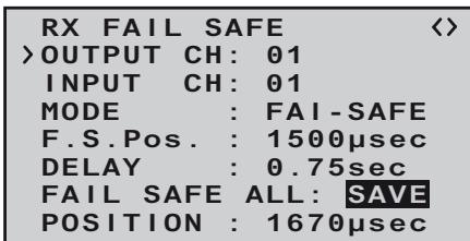
After pressing the INC+DEC button once more, the display reverts from "SAVE" to "NO". This indicates that the position of all the servos affected by the procedure have now been stored, and have also been adopted in the "F.S(Pos)" line. At the same time the position for the current OUTPUT CH (servo socket) is immediately displayed on the screen.
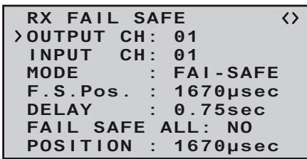
Switch the transmitter off, and check the Fail-Safe positions by observing the servo movements.
"Fail-Safe" in combination with "channel mapping". It is clearly desirable that mapped servos - i.e. servos which are controlled by a common control channel (INPUT CH) - should respond in the same way when interference occurs, so the corresponding settings of the INPUT CH determine the behaviour of mapped servos. For example, if you are using a GR-16 eight-channel receiver, Order No. 33508, and receiver servo sockets 6, 7 and 8 are mapped together, i.e. if the same control channel "04" is assigned as INPUT CH to OUTPUT CH (servo sockets) 06, 07 and 08 ...
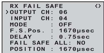
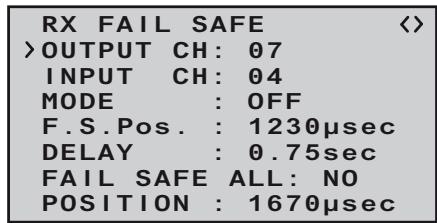
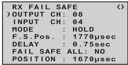
... then INPUT CH 04 determines the Fail-Safe behaviour of the three servos connected to control channel 4, regardless of the individual settings of the OUTPUT CH for INPUT CH 04:
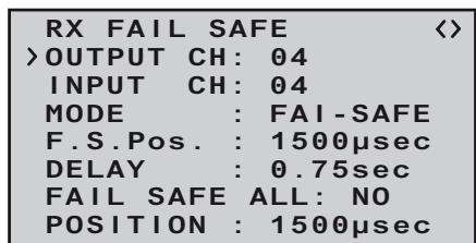
This also applies, for example, if it is mapped in turn to INPUT CH 01:
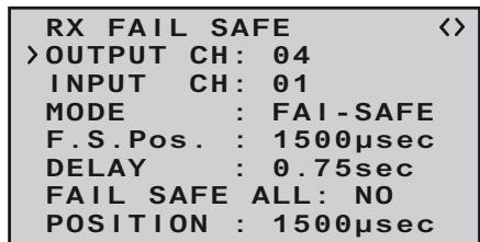
In this case servo socket 04 would respond in accordance with the Fail-Safe settings for CH 01. In contrast, the response or delay time set in the "DE-LAY" line always applies uniformly to all channels which are set to "FAIL-SAFE".
RX FREE MIXER
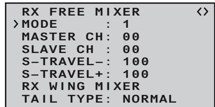
| Value | Explanation | Possible settings |
| MODE | Mixer select | 1, 2 or 3 |
| MASTER CH | Primary channel | 0, 1 ... according to transmitter |
| SLAVE CH | Secondary channel | 0, 1 ... according to receiver |
| S-TRAVEL- | Negative mix value | 0 ... 100% |
| S-TRAVEL+ | Positive mix value | 0 ... 100% |
| RX WING | Tail type | NORMAL, V-TAIL |
| MIXER | | ELEVON (aileron / elevator mixer for deltas and flying wings) |
MIXER
Up to three mixers can be programmed simultaneously. You can switch between mixer 1, mixer 2 and mixer 3 using "MIXER".
The following settings on this screen always apply to the mixer selected in the MIXER line.
Important note:
If you have already programmed mixer functions in the "Tail type" menu, page 105, check very carefully that those mixers do not overlap with those of the "RX FREE MIXER" menu.
MASTER CH ("from")
The signal present at the MASTER CH (master channel) is mixed into the SLAVE CH (slave channel) to a user-variable extent, following the same principles as described in detail in the section entitled "Free mixers" on page 107.
Select "00" if no mixer is to be set.
SLAVE CH ("to")
A proportion of the signal of the MASTER CH (master channel) is mixed into the SLAVE CH (slave channel); the mixer ratio is determined by the percentage figures entered in the "TRAVEL- " and "TRAVEL ^+ " lines.
Select "00" if no mixer is to be set.
TRAVEL- + (mixer ratio in %
The mixer ratio in relation to the MASTER signal is determined separately for each direction by the values entered in these two lines.
TAIL TYPE
The following model types are also available in the "Tail type menu (see page 105), and should normally be set up at that point. If you have done this, you should always leave the TAIL TYPE at NO MIX.
However, if you prefer to use the receiver's integral mixers, you can select the pre-set mixer function for the corresponding model type:
NORMAL
This setting corresponds to the classic aircraft type with tail-mounted stabiliser panels and separate rudder and elevator. No mixer function is required for this model type.
V-TAIL
For this model type the control functions elevator and rudder are linked together in such a way that each of the two control surfaces - actuated by a separate servos - carries out superimposed elevator and rudder functions.
The servos are usually connected to the receiver as follows:
OUTPUT CH 3: left V-tail servo
OUTPUT CH 4: right V-tail servo
If you find that the servos rotate in the wrong direction, please see the notes on page 111.
ELEVON (delta / flying wing models)
The servos connected to outputs 2 and 3 assume superimposed aileron and elevator functions. The servos are usually connected to the receiver as follows:
OUTPUT CH 2: left elevon
OUTPUT CH 3: right elevon
If you find that the servos rotate in the wrong direction, please see the notes on page 111.
RX CURVE (EXPO)
RX CURVE
CURVE1 CH : 02
TYPE : A
CURVE2 CH : 05
TYPE : A
CURVE3 CH : 04
TYPE : B
5CH FUNCTION: SERVO
| Value | Explanation | Possible settings |
| CURVE1, 2 or 3 CH | Channel assignment of the selected curve setting | 1 ... according to receiver |
| TYPE | Curve type | A, B, C see illustration |
TYPE A
Expo = -100%
DR = 125%
TYPE B
linear
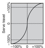
Transmitter control travel
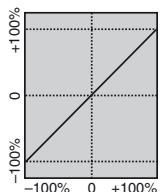
Transmitter control travel
TYPE C
Expo = +100%
DR=70%
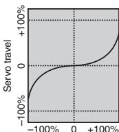
Transmitter control travel
In most cases a non-linear control function is used for aileron (channel 2), elevator (channel 3) and rudder (channel 4), and the default settings assume that this is the case.
For example, if you have set "AIL" at the transmitter, and
wish to use the RX CURVE option - then two curves must be set:
If you ignored this, the left and right ailerons would exhibit different control characteristics.
The RX CURVE function can be used to manage the control characteristics for up to three servos:
CURVE 1,2 or 3 CH
Select the desired control channel (INPUT CH) for the first servo.
The following setting in TYPE only affects the channel you select at this point.
TYPE
Select the servo curve:
A: EXPO = -100% and DUAL RATE = 125%
The servo responds slowly to stick movements around the neutral position, but the curve becomes steeper with increasing control travel.
B: Linear setting
The servo follows the stick movement with a linear response.
C: EXPO = +100% and DUAL RATE = 70%
The servo responds slowly to stick movements around the neutral position, but the curve becomes steeper with increasing control travel.
Note:
The control characteristics programmed at this point
also affect mapped receiver outputs.
RX SERVO TEST
| RX SERVO TEST < |
| >ALL-MAX : 2000μsec |
| ALL-MIN : 1000μsec |
| TEST : STOP |
| ALARM VOLT : 3.8V |
| ALARM TEMP+: 70°C |
| ALARM TEMP-:-10°C |
| CH OUTPUT TYPE:ONCE |
| Value | Explanation | Possible settings |
| ALL-MAX | Servo travel on the “+” side for all servo outputs in the servo test | 1500 ... 2000 μs |
| ALL-MIN | Servo travel on the “-” side for all servo outputs in the servo test | 1500 ... 1000 μs |
| TEST | Test procedure | START / STOP |
| ALARM VOLT | Alarm limit for the receiver low-voltage warning | 3,0 ... 6,0 V
Default setting: 3,8 V |
| ALARM TEMP+ | Alarm limit for excessive receiver temperature | 50 ... 80 °C
Default setting: 70 °C |
| ALARM TEMP- | Alarm limit for excessively low receiver temperature | -20 ... +10 °C
Default setting: -10 °C |
| CH OUTPUT TYPE | Channel sequence | ONCE, SAME, SUMI, SUMO |
ALL MAX (maximum servo travel)
In this line you can set the maximum servo travel for the servo test on the plus side of control travel.
2000 s corresponds to full travel, 1500 s corresponds to the neutral position.
ALL MIN (minimum servo travel)
In this line you can set the maximum servo travel for the servo test on the minus side of control travel.
1000 μs corresponds to full travel, 1500 μs corresponds to the neutral position.
TEST
In this line you can start and stop the receiver's integral servo test.
Press the NC++DEC button to activate the input field:
| RX SERVO TEST <ALL-MAX : 2000μsecALL-MIN : 1000μsec>TEST : STOPALARM VOLT : 3.8VALARM TEMP+: 70°CALARM TEMP-:-10°CCH OUTPUT TYPE:ONCE |
Now select START with one of the arrow buttons of the right-hand four-way button:
| RX SERVO TEST < |
| ALL-MAX : 2000μsec |
| ALL-MIN : 1000μsec |
| >TEST : START |
| ALARM VOLT : 3.8V |
| ALARM TEMP+: 70°C |
| ALARM TEMP-:-10°C |
| CH OUTPUT TYPE:ONCE |
Press the INC+DEC button to start the test-run. The input field now reverts from highlighted to "normal":
| RX SERVO TEST < |
| ALL-MAX : 2000μsec |
| ALL-MIN : 1000μsec |
| >TEST : START |
| ALARM VOLT : 3.8V |
| ALARM TEMP+: 70°C |
| ALARM TEMP-:-10°C |
| CH OUTPUT TYPE:ONCE |
To stop the servo test, re-activate the input field as described previously, then select STOP and confirm your choice with the INC+DEC button.
ALARM VOLT (low receiver voltage warning)
ALARM VOLT monitors the receiver voltage. The threshold can be set to any value within the range 3.0 to 6.0 Volt. If the voltage falls below the set alarm limit, an audible signal (interval beeping, long / short) is triggered, and "VOLT.E" flashes at top right in all "RX ..." screen displays:
| RX SERVO VOLT.E <> |
| OUTPUT CH: 01 |
| REVERSE: 0FF |
| CENTER: 1500μsec |
| TRIM: -000μsec |
| TRAVEL-: 150% |
| TRAVEL+: 150% |
| PERIOD: 20msec |
The parameter "R-VOLT" is also highlighted in the "RX DATAVIEW" display:
| RX DATAVIEW VOLT.E > |
| S-QUA100%S-dBM-030dBM |
| S-STR100% R-TEM.+28°C |
| L PACK TIME 00010msec |
| R-VOLT :03.7V |
| L.R-VOLT:03.5V |
| SENSOR1 :00.0V 00°C |
| SENSOR2 :00.0V 00°C |
ALARM TEMP +/- (receiver temperature monitor)
These two options monitor the temperature of the receiver: a lower limit value "ALARM TEMP-" (-20 ... +10°C) and an upper limit value "ALARM TEMP+" (50 ... 80°C) can be programmed. If the temperature exceeds the upper limit or falls below the lower one, an audible signal (continuous beeping) is triggered, and "TEMP" appears at top right in all receiver displays. The parameter "R-TEMP" is also highlighted in the "RX DATAVIEW" display.
Ensure that the receiver remains within the permitted temperature range under all flight conditions (ideally between -10 and +50^ ).
CH OUTPUT TYPE
At this point you can select how the receiver outputs are to be addressed.
ONCE
The receiver servo sockets are addressed in sequence; this is recommended for use with analogue servos. At this setting the servos are automatically operated at a frame rate of 20 ms (30 ms with the twelve-channel receiver, Order No. 33512) - regardless of what is set or displayed in the "PERIOD" line of the "RX SERVO" display.
SAME
The receiver servo sockets are addressed in parallel blocks of four, i.e. if you are using the GR-12 receiver included in the set, channels 1 to 4 and channels 5 and 6 each receive their control signals simultaneously.
This is recommended for use with digital servos, and especially where multiple servos are employed for a single function (e.g. ailerons), to ensure that the
groups of servos run absolutely synchronously. If you are using digital servos, we recommend that you set 10 ms in the "PERIOD" line of the "RX SERVO" display so that you can exploit the fast response of these servos. If you are using analogue servos, it is essential to select "20 ms".
If you choose the faster setting, please take particular care when selecting the receiver power supply: since up to four servos can start moving simultaneously, the load on the battery is fairly severe, so it must be a high-performance type.
SUMO (Sum signal OUT)
A HoTT receiver configured as SUMO constantly generates what is known as a sum signal from the control signals of all its control channels. This signal is present, for example, at servo socket 6 of the GR-12 receiver.
The maximum sum signal can be set independent from the receiver up to 16 channels, e.g. a 6-channel receiver can be programmed on SUMO 12 and transmits all 12 channels on the output.
After SUMO is selected and saved with INC+DEC, the inverse marker jumps forward to the channel number, here 06:
Pressing INC or DEC selects the number of channels to be transmitted in the sum signal. INC+DEC saves the settings.
The receiver outputs are addressed in sequence at a frame rate of 20 ms (30 ms with the GR-24 receiver, Order No. 33512), even if you have set 10 ms in the "PERIOD" line of the "RX SERVO" screen page.
Although primarily intended for "satellite mode" with two HoTT receivers, as described below, the sum signal generated by the receiver defined as SUMO can
also be used, for example, to control a flybarless system, or to control a flight simulator (using the adapter lead, Order No. 33310).
Intended primarily for the following described „satellite mode“ of two-HoTT receivers, the of the receiver generated sum signal SUMO can be used, for example, also for Flybarless systems or via the adapter cable Order No. 33310 for of flight simulators.
In ...
Satellite mode
... two HoTT receivers are inter-connected using a three-core connecting lead (Order No. 33700.1 (300
| RX SERVO TEST < |
| ALL-MAX : 2000μsec |
| ALL-MIN : 1000μsec |
| >TEST : START |
| ALARM VOLT : 3.8V |
| ALARM TEMP+: 70°C |
| ALARM TEMP-:-10°C |
| CH OUTPUT TYPE:SUMO96 |
mm) or 33700.2 (100 mm) by the highest-numbered servo sockets. For more details on this please visit www.graupner.de on the Internet.
All channels of the HoTT receiver which is configured as SUMO, and is defined as the satellite receiver, are constantly transferred to the second HoTT receiver - the primary receiver - via this connection. The primary receiver must be programmed as the ...
Note that the signal only ever moves in one direction: towards the SUMI.
However, if reception fails, the receiver defined as SUMI only uses the sum signal coming from the
SUMO if at least one channel at the SUMI is programmed to Fail-Safe.
If the receiver programmed as the satellite (SUMO) suffers signal reception failure, the servos connected to that receiver take up the Fail-Safe positions programmed in the satellite receiver, regardless of the primary receiver.
If, in contrast, reception fails at both receivers simultaneously, then the receiver software (the version current at the time of printing these instructions) always reverts to the SUMO's fail-safe settings. However, mutual interactions can certainly not be ruled out in individual cases, and for this reason we urgently advise you to carry out appropriate tests BEFORE flying a model.
This receiver configuration is recommended in particular circumstances: for example, if one of the two receivers has to be installed in an unfavourable position in the model, or if there is a danger that the received signal will be weak in certain flight attitudes, perhaps due to a turbine, carbon fibre in the airframe, or a similar problem, with the result that sporadic range problems might be expected.
For this reason it is essential to connect the most important control functions to the primary receiver (the one programmed as SUMI), so that interference to the satellite receiver (SUMO) does not cause the model to go out of control.
Telemetry data, such as the voltage of the airborne power supply, are only sent to the transmitter by the satellite receiver (configured as SUMO), i.e. all telemetry sensors must be connected to the satellite receiver (SUMO).
Each receiver should be connected to the shared po
wer supply using its own power lead. If high currents can be expected, duplicated power connections are recommended. However, if each of the two receivers is to be powered by its own battery, then it is
essential to withdraw the central (red) wire from one of the two satellite lead connectors, as shown in the illustration.
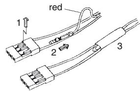
If you wish to carry out further programming, such as the Fail-Safe settings, disconnect the three-core satellite connection between the two receivers, and switch on just the receiver you wish to address. Note that you may also need to change the binding sequence.
DATA VIEW
MODEL SELECT
Select the desired menu line „MODEL SELECT“ using the INC button.
Now press ENTER ...

and again ENTER ...
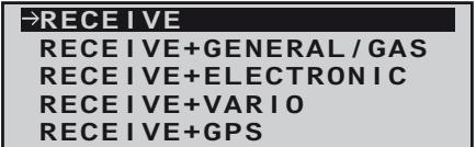
... press the INC -button to choose the sensor with the arrow and finally press ENTER to select:
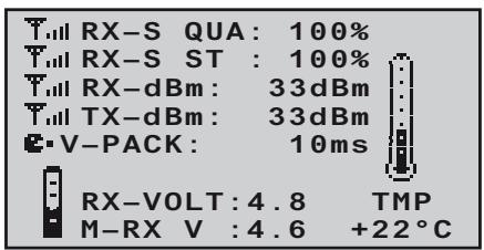
Just like described in the menu „MODEL SELECT“ ...
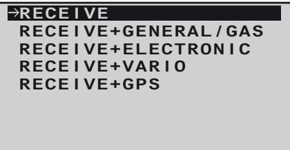
...the output can be selected to graphically processed data from a sensor connected to the receiver if necessary. These data are then presented according to the following graphic displays.
Scroll back and forth between the different graphic displays with the INC or DEC key and choose by pressing ENTER, press ESC to return back to the basic display.
Note:
The order of displays described below follows the sequence when pressing the NC button.
More details about the following modules can be found in the appendix and on the internet at www.graupner.de for the relevant product.
RECEIVER
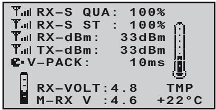
This screen displays the data which can also be viewed in the "RX DATAVIEW" screen of the telemetry menu "SETTING & DATA VIEW", but in graphic form.
The meanings are as follows:
| Value | Explanation |
| RX-S QUA | Signal quality in % |
| RX-S ST | Signal strength in % |
| RX-dBm | Receive performance in dBm |
| TX-dBm | Transmit power in dBm |
| V PACK | shows the longest period in ms in which data packets were lost in transmission from transmitter to receiver |
| RX-VOLT | Current receiver operating voltage in Volt |
| M-RX V | Lowest receiver operating voltage in Volt since the last time it was switched on |
| TMP | The thermometer indicates the receiver's current operating temperature |
RX + GENERAL MODUL
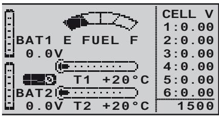
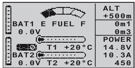
If a General Engine module, Order No. 33610, or a General Air module, Order No. 33611, is connected to the receiver, then this screen provides a graphic display of the data supplied by it. For more information on these modules please see the Appendix, or refer to the product on the Internet at www.graupner.de.
Depending on the types of sensor fitted to the modules, the display constantly shows the following data:
The actual voltage of up to two rechargeable batteries (BAT1 and BAT2); the measured values from up to two temperature sensors (T1 and T2) and a fueltank level indicator.
At the right-hand edge the screen shows either an alternating list of the actual cell voltages of a LiPo battery with up to six cells, or the current altitude relative to the location, climb / descent in m/1sec and m/3sec, current in Ampere plus the actual voltage of the battery connected to the sensor.
The meanings are as follows:
| Value | Explanation |
| BAT1 / BAT2 | Battery 1 / Battery 2 |
| FUEL | Fuel level / Fueltank indicator |
| E / F | Empty / full |
| T1 / T2 | Temperature of sensor 1 / sensor 2 |
| CELL V | Cell voltage of cell 1 ... max. 6 |
| 1500 | RPM |
| ALT | Current altitude |
| 0m1 | m/1 sec climb / descent |
| 0m3 | m/3 sec climb / descent |
| POWER V. | Actual voltage of the drive battery |
| A | Actual current of drive battery |
| 450 | Actual used capacity |
RX + ELECTRIC AIRMODUL
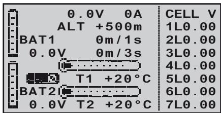
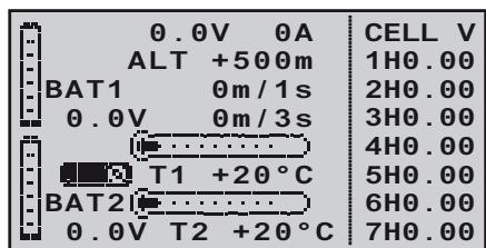
If an Electric-Air module, Order No. 33620, is connected to the receiver, then this screen provides a graphic display of the data supplied by it. For more information on this module please see the Appendix, or refer to the product on the Internet at www.graupner.de.
Depending on the types of sensor fitted to the module, the display constantly shows the following data:
The actual voltage of up to two rechargeable batteries (BAT1 and BAT2); the measured values from up to two temperature sensors (T1 and T2); the current altitude relative to the location, and the climb / descent of the model in m/1sec and m/3sec; the centre of the screen also displays the current actually being drawn from a power source.
At the right-hand edge the screen shows an alternating display of the actual cell voltages of the battery packs (max. seven cells each) connected to balancer sockets 1 (L) or 2 (H).
The meanings are as follows:
| Value | Explanation |
| V | Actual voltage |
| A | Actual current |
| BAT1 / BAT2 | Battery 1 / Battery 2 |
| ALT | Current altitude |
| m/1s | m/1 sec climb / descent |
| m/3s | m/3 sec climb / descent |
| T1 / T2 | Temperature from sensor 1 / 2 |
| CELL.V | Cell voltage of cell 1 ... max. 14 |
| L | Balancer socket 1 |
| H | Balancer socket 2 |
RX + VARIO
| m/1s
θ | H | RXSQ
θ |
| m/3s
θ | ALT
+500 | MAX
+500m |
| m/10s
θ | L | MIN
+500m |
If a Vario module, Order No. 33601, is connected to the receiver, then this screen provides a graphic display of the data supplied by it. For more information on this module please see the Appendix or refer to the product on the Internet at www.graupner.de.
The meanings are as follows:
| Value | Explanation |
| ALT | Current altitude |
| RXSQ | Signal strength of the signal picked up by the receiver in % |
| MAX | The pre-set altitude limit relative to the launch point; above this altitude the transmitter emits audible warning signals |
| MIN | The pre-set altitude limit below the launch point; below this altitude the transmitter emits audible warning signals |
| m/1s | m/1 sec climb / descent |
| m/3s | m/3 sec climb / descent |
| m/10s | m/10 sec climb / descent |
RX + GPS
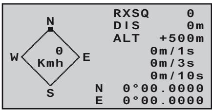
If a GPS module with integral vario, Order No. 33600, is connected to the receiver, then this screen provides a graphic display of the data supplied by it. For more information on this module please see the Appendix, or refer to the product on the Internet at www.graupner.de.
The centre of the screen shows the current positional data and the model's speed; the display also shows the model's current altitude in relation to the launch point, its climb / descent rate at m/1 sec, m/3 sec and m/10 sec, the current reception quality and the model's range from the launch point.
The meanings are as follows:
| Value | Explanation |
| W / N / E / S | West / North / East / South |
| Kmh | Speed |
| RXSQ | Signal strength of downlink channel |
| DIS | Distance |
| ALT | Current altitude relative to launch point |
| m/1s | m/1 sec climb / descent |
| m/3s | m/3 sec climb / descent |
| m/10s | m/10 sec climb / descent |
The mx-10 HoTT transmitter can be combined by wireless means to form a Trainer system. Here, the second transmitter must not be the mx-10 HoTT also, every other HoTT transmitter with the possibility of wireless Trainer operation is suitable. Therefore please read the manual of your HoTT system!
Switching from the normal operating mode to the transmitters teacher or student mode is done by the mode switch on the left top side of the transmitter:
Mode normal teacher pupil
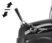
To change the mode, move the mode switch on the transmitter in the desired position, press and hold the BIND-button and then switch on the transmitter.
To display the selected mode ...
| LED Status | Buzzer | Description |
| orange LED on | - | Transmitter mode „normal“, country setting: general |
| orange LED flashes | beeping twice after switching on | Transmitter mode: pupil |
| orange LED flashes twice | 2x beeping twice after switching on | Transmitter mode: teacher |
See LED and buzzer signals on page 88.
Important Note:
The following description is based on the time of printing this manual current version 1.00 of the transmitter software, and is equally valid for all previous Software versions. It can not be excluded that after the next update, the following description will not be correspondend with the functionality of the HoTT Trainer system.
Teacher transmitter settings mx-10 HoTT
The trainer model must be programmed completely, i. e. with all its functions including trims and any mixer functions in the mx-10 HoTT Teacher transmitter. This means that it must be possible to control the trainer model fully, without restriction, by the Teacher transmitter. But, at the conclusion of these preparations, the trainer model must be bound to the Pupil transmitter. A detailed description of the binding process can be found on page 106 and 109.
Note when using the mx-10 HoTT as pupil transmitter: the mx-10 HoTT binding procedure can only be done in „normal“ mode. Before using the transmitter in Pupil mode, bind the receiver in mode „normal“, then switch to the mode „pupil“. In addition, no mixer may be activated, move the jumper in the middle position „NO MIX“, see also page 105.
All five transmitter control functions of the Teacher transmitter "T" can be transferred to the pupil transmitter "P". The stick mode of the pupils transmitter may deviate from the teacher transmitter, because the stick mode and mixers will be transferred from the teachers transmitter. Therefore the teachers transmitter must be properly programmed for the training model with all functions and mixers.
After the pupils transmitter is bound to the trainer model, set the mx-10 HoTT in the teacher mode. To change the mode, move the mode switch on the transmitter in the „teacher“ position, press and hold the BIND-button and then switch on the transmitter.
Now press the BIND-button of the puplis transmitter: mx-10 HoTT: press and hold
In the following the student programming for the mx-12/16/20 HoTT is described. Please read also the instructions for your remote control system!
Switch on the transmitter, and use the arrow buttons of the left or right-hand four-way button to leaf through on both transmitters to the "Trainer" menu point of the multifunction menu. (The trainer model's receiving system, previously bound to the Pupil transmitter, does not need to be switched on during the following procedure.)
servo set.
contr set.
D/R expo
phase trim
wing mixer
free mixer
servo disp
basic sett
fail-safe
telemetry
teach/pupil
info disp
Press the central SET button of the right-hand four-way button to open the following menu point:
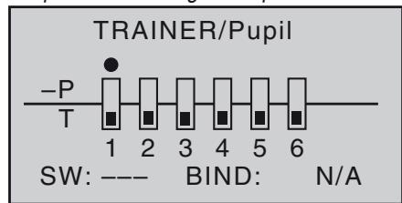
The illustration above shows the initial state of this
menu: no transmitter controls have been released to the Pupil (■), and no switches have been assigned (SW: --- bottom right and -S on left of illustration).
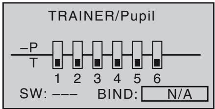
Start the "BINDING" process first at the Pupil transmitter by pressing the central SET button of the right-hand four-way button, the display nV changes to the message BINDING:
Binding the Pupil transmitter to the Teacher transmitter
Note:
During the binding procedure the distance between the two transmitters should not be too great. You may need to change the relative position of the two transmitters and initiate the binding process a second time.
The teachers mx-10 transmitter HoTT must be bound conclusively to the pupils transmitter. To do this press the BIND button on the front. After a few seconds a successful binding operation is confirmed by a short beep, the trainer model can be controlled with the teacher transmitter.
When using a mx-12/16/20 HoTT pupil transmitter, BINDING changes to ON:
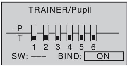
To perform the transfer, move the mode switch of the mx-10 HoTT in forward direction- in the mode „pupil". As long as this switch is pressed, the pupil has control over the trainer model. Release the key to give the control back to the teacher transmitter.
Note: even if the transmitter is turned off temporarily, the teacher mode remains active when turned on again.
Pupil transmitter settings mx-10 HoTT
The trainer model must be programmed completely, i. e. with all its functions including trims and any mixer functions in the mx-10 HoTT Teacher transmitter. This means that it must be possible to control the trainer model fully, without restriction, by the Teacher transmitter. But, at the conclusion of these preparations, the trainer model must be bound to the Pupil transmitter.
When assigning the control functions the usual conventions should be observed:
| Channel | Function |
| 1 | Throttle / Collective pitch |
| 2 | Aileron / Roll |
| 3 | Elevator / Pitch-axis |
| 4 | Rudder / Tail rotor |
The HoTT receiver of the trainer model must be „bound“ to the pupils transmitter. A detailed description of the binding process can be found on page 106 and 109.
Note: the mx-10 HoTT binding procedure can only be done in „normal“ mode. Before using the transmitter in Pupil mode, bind the receiver in mode „normal“, then switch to the mode „pupil“. In addition, no mixer may be activated, move the jumper in the middle position „NO MIX“, see also page 105.
After the pupils transmitter is bound to the trainer model, set the mx-10 HoTT in the pupils mode. To change the mode, move the mode switch on the transmitter in the "pupil" position, press and hold the BIND-button and then switch on the transmitter.
Binding the Pupil transmitter to the Teacher transmitter
Note:
During the binding procedure the distance between the two transmitters should not be too great. You may need to change the relative position of the two transmitters and initiate the binding process a second time.
Press and hold the BIND-button of the pupils transmitter mx-10 HoTT.
Teacher transmitter:
mx-10 HoTT: press and hold the BIND-button
After a few seconds the successful binding is confirmed by a short beep, the trainer model can be controlled with the teacher transmitter.
mx-12/16/20 HoTT: Switch on the transmitter, and use the arrow buttons of the left or right-hand four-way button to leaf through on both transmitters to the "Trai
ner" menu point of the multi-function menu. (The trainer model's receiving system, previously bound to the Pupil transmitter, does not need to be switched on during the following procedure.):
servo set.
contrset.
D/R expo
phase trim
wing mixer
free mixer
servo disp
basic sett
fail-safe
telemetry
teach/pupil
info disp
Press the central SET button of the right-hand four-way button to open the following menu point:
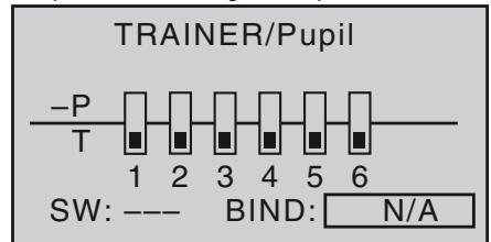
Press the central SET button of the right-hand four-way button to release the control channels to be transferred to the Pupil. When you do this, the corresponding symbol changes from to . For example:
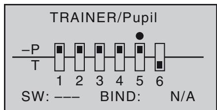
In contrast to the wired Trainer system described in the previous section, in which TRANSMITTER CONTROL SIGNALS are released to the Pupil exclusively, it is CONTROL CHANNELS which are transferred when
using the wireless HoTT system which is described in this section.
For example, if the aileron function (2) is to be transferred, and if the model is equipped with two aileron servos which are usually connected to receiver sockets 2 and 5, then in the wireless system control channels 2 and 5 must also be transferred. You still have to assign a Trainer transfer switch on the right of the screen so that you can actually transfer control to the Pupil. This is accomplished by using the arrow buttons of the left or right-hand four-way button to place the marker next to "SW" at bottom right, and assign a switch.
We recommend that you use the momentary switch SW 1 as the transfer switch, to ensure that the Teacher transmitter can regain control instantly at any time.
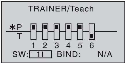
Now use the arrow buttons of the left or right-hand four-way button to move the marker to "BIND: N/A" on the right:
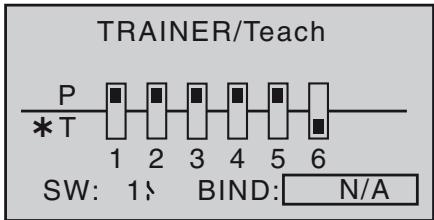
Close the previously defined transfer switch ...
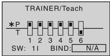
... and start the "BINDING" process by pressing the central SET button of the right-hand four-way button. As soon as this process is concluded, both screens display "ON" instead of the flashing message "BINDING":
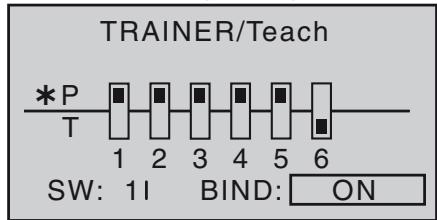
Note: even if the transmitter is turned off temporarily, the teacher mode remains active when turned on again.
Trainer mode operations
Connect the two transmitters using the wireless Trainer mode.
Important Note: Be sure to check all functions BEFORE teacher-student operation for proper change-over.
While the operation it is no problem for the Teacher and Pupil to stand a little way apart. However, you should never exceed a distance of 50m (this is known as the call range), and no other persons should stand between
the Teacher and Pupil, as this could reduce the effective range. Please note also that the wireless Trainer function exploits the downlink connection, and for this reason no telemetry data are transmitted from the model in this mode.
If it should occur that the link between the Teacher and Pupil transmitters is lost during Trainer mode operations, note that the Teacher transmitter automatically assumes control of the model.
In this situation, if the Trainer change-over switch is in the "Pupil" position, then the central LED on the mx-10 HoTT Teacher transmitter starts to flash 4-times orange and emits a audible warning signal. I
In either situation your first recourse should be to reduce the distance between the two transmitters. If this does not help, land the model immediately, and seek the cause.
Checking the system
Possible errors:
- Pupil transmitter not ready
- Teacher transmitter and HoTT receiver in trainer model not correctly "bound".
Appendix

PRX (Power for Receiver)
Order No. 4136
A highly developed stabilised receiver power supply with intelligent power management.
The unit constitutes a stabilised user-selectable power supply for the receiver, and provides a further enhancement in the reliability of the airborne power supply. It is designed for use with different types of receiver battery, to ensure that it is straightforward and versatile in use. When the model is operating, even brief collapses in battery voltage are stored and displayed, offering the user the means of detecting a receiver battery which is not "up to the job", or failing.
- For use with one or two receiver batteries (simultaneous discharge if two batteries are employed)
- Suitable for five-cell or six-cell NiMH batteries, or two-cell LiPo or LiFe packs. Graupner/JR, G3.5, G2 and BEC connector systems.
- Three user-selectable receiver power voltage levels: 5.1V / 5.5V / 5.9V .
- Two ultra-bright LEDs indicate the operational status of batteries 1 and 2 separately.
- Integral high-quality On / Off switch.
- Constructed to cope with high-current applications.
- Low-profile switch and LEDs to avoid spoiling the appearance and efficiency of the model.
- Straight-through design of mounting lugs, LEDs and switch for simple installation using drilling template (supplied).
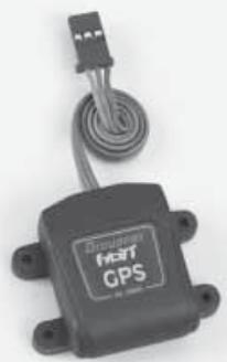
Graupner HoTT GPS / Vario module
Order No. 33600
Vario with altitude signals and five different tones for climb and descent, plus GPS with range measurement, distance measurement, speed indicator, display of flight direction and co-ordinates
Additional warning thresholds for min. altitude, max. altitude, two-stage climb and descent rate
- Altitude display, storage of min. and max. altitude
Variable warning time: OFF, 5, 10, 15, 20, 25, 30 seconds, constant
Variable warning repeat time: constant, 1, 2, 3, 4, 5 min, once
- The GPS / Vario sensor can be connected directly to the receiver's telemetry input.
Specification, vario
- Altitude measurement: -500 m ... +3000 m
Resolution: 0.1 m
- Sensitivity, vario: 0.5m / 3s , 1m / 3s , 0.5m / s , 1m / s , 3m / s , programmable per beep
- Calculated average value: 4 - 20 measurements per measured value, programmable
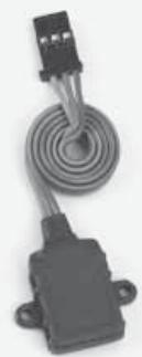
Graupner HoTT Vario module
Order No. 33601
Vario with altitude signals and five different tones for climb and descent; altitude display and storage of min. and max. altitude.
Additional warning thresholds for min. altitude, max. altitude, two-stage climb and descent rate
Variable warning time: OFF, 5, 10, 15, 20, 25, 30 seconds, constant
Variable warning repeat time: constant, 1, 2, 3, 4, 5 min, once
- The vario sensor can be connected directly to the receiver's telemetry input.
Specification
- Altitude measurement: -500 m ... +3000 m
Resolution: 0.1m
- Sensitivity, vario: 0.5 ~m / 3 ~s, 1 ~m / 3 ~s, 0.5 ~m / s, 1 ~m / s, 3 ~m / s , programmable per beep
- Calculated average value: 4 - 20 measurements per measured value, programmable
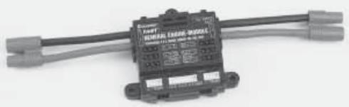
Graupner HoTT General Engine Module
Order No. 33610
General sensor for Graupner HoTT receivers and models with internal-combustion or electric power system:
- 2 x temperature and voltage measurements with warning thresholds for min. and max. voltage and min. and max. temperature
- Individual cell measurement with min. voltage warning thresholds
- Voltage, current and capacity measurement with warning thresholds for min. and max. voltage, max. capacity and max. current
- Programmable current limiting
- Current measurement with 2 × 1 mOhm shunt resistors in parallel = 0.5 mOhm
- Rev-count measurement and warning thresholds for min. and max. rotational speed
- Fuel measurement with warning thresholds in 25% increments (requires software update)
- User-variable warning time: OFF, 5, 10, 15, 20, 25, 30 seconds, constant
- User-variable warning repeat time: constant, 1, 2, 3, 4, 5 min, once
- 2 × temperature measurement, optionally 0 to 120^ C or 200^ C , also voltage measurement up to 80 ~V DC
- 1 x rev-count measurement up to 100,000 rpm with two-blade propeller
- 1 x speed controller / servo input, 1 x speed governor input, 1 x speed controller / servo output for rotational speed governor
etc. see product at www.graupner.de
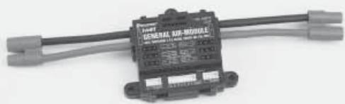
Graupner HoTT General Air Module
Order No. 33611
General sensor for Graupner HoTT receivers and models with internal-combustion or electric power system:
- Vario with altitude signals, climb and descent signals, and additional warning thresholds for min. altitude, max. altitude, climb and two-stage descent rate
- Altitude indicator (-500 ... +3000 m), storage of min. and max. altitude
- 2 × temperature and voltage measurements with warning thresholds for min. and max. voltage and min. and max. temperature
- Individual cell measurement with min. voltage warning thresholds
- Voltage, current and capacity measurement with warning thresholds for min. and max. voltage, max. capacity and max. current
- Rev-count measurement and programmable speed governor, also warning thresholds for min. and max. rotational speed
- Fuel measurement with warning thresholds in 25% increments (requires software update)
- User-variable warning time: OFF, 5, 10, 15, 20, 25, 30 seconds, constant
- User-variable warning repeat time: constant, 1, 2, 3, 4, 5 min, once
- 2 × temperature measurement, optionally 0 to 120^ C or 200^ C , also voltage measurement up to 80 ~V DC
- 1 x rev-count measurement up to 100,000 rpm with two-blade propeller
etc. see product at www.graupner.de

Graupner HoTT Electric Air-Module
Order No. 33620
General sensor for Graupner HoTT receivers and electric-powered models:
- Vario with altitude signals, climb and descent signals, and additional warning thresholds for min. altitude, max. altitude, two-stage climb and descent rate
- Altitude indicator (-500 ... +3000 m), storage of min. and max. altitude.
- 2 × temperature and voltage measurements with warning thresholds for min. and max. voltage and min. and max. temperature
- Individual cell measurement 2 ... 14S with min. voltage warning thresholds
- Voltage, current and capacity measurement with warning thresholds for min. and max. voltage, max. capacity and max. current
- User-variable warning time: OFF, 5, 10, 15, 20, 25, 30 seconds, constant
- User-variable warning repeat time: constant, 1, 2, 3, 4, 5 min, once
- 2 × temperature measurement, optionally 0 to 120^ C or 200^ C , also voltage measurement up to 80 ~V DC
- 1 x speed controller input, 1 x speed controller output for power reduction due to low voltage of individual cells
- 1 x current, voltage and capacity measurement, up to 150 A (peak 1 sec. 320 A) and up to 60 V
- 1 x individual cell monitoring for 2 - 14S Lithium batteries (LiPo, Lilo, LiFe)
etc. see product at www.graupner.de
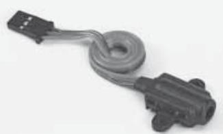
Graupner HoTT RPM magnet sensor
Order No. 33616
Graupner HoTT RPM optical sensor
Order No. 33615
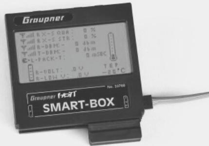
Graupner HoTT Smart-Box
Order No. 33700
A vast range of different functions combined in a single device: that's what destines the SMART-BOX to be your intelligent companion in future. Whether you want to display telemetry data in real time, or enter changes to your HoTT system, the large-area screen with 8 × 21 characters makes the task simple. The flexible Smart-Box includes an integral buzzer for generating audible signals and warnings for even greater flexibility and practicality.
The installation set supplied makes it easy to mount the unit on the support bars of hand-held transmitters, allowing you to position it in such a way that you can read off telemetry data in real time while you control your model.
The user-update facility ensures that the SMART-BOX is always up-to-date, and provides a route for expanded functions in future.
- Transmitter voltage display with user-variable warning threshold
- Range check
- Receiver temperature
Servo reverse
Servo travel
- Channel swap
- Mixer settings
Country setting
Signal quality
- Receiver voltage
- Servo neutral position
- Cycle time
- Fail-Safe settings
- Servo test
Dimensions: approx. 76mm× 72mm× 17mm (L× W× H)
Weight: approx. 55g
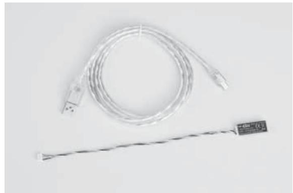
Graupner HoTT USB Interface cable
Order No. 7168.6
This USB interface cable is used with the separately available adapter cable No. 7168.6A for updating receivers and sensors.
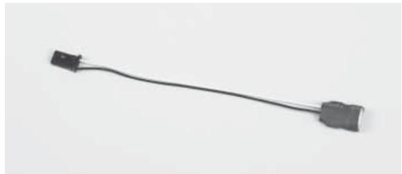
Graupner HoTT adapter cable USB interface/JR
Order No. 7168.6A
This adapter cable is used with the separately available USB interface cable cable No. 7168.6 for updating receivers and sensors.


Sommaire
Généralités
Computer System mx-10
Radiocommande 5 voies en 2,4 GHz, technologie Graupner HoTT (Hopping Telemetry Transmission)

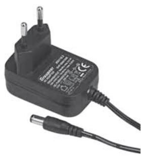
Recommendations important :
3. Firmware Update Utility
Accus Nano-phosphate 2 éléments (A123)
| m/1s
θ | H | RXSQ
θ |
| m/3s
θ | ALT
+500 | MAX
+500m |
| m/10s
θ | B | MIN
+500m |
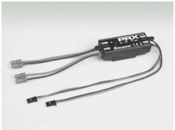
PRX (Power for Receiver)
Réf.Cde 4136
Graupner mx-10 HoTT #33110
FCC ID: ZKZ-MX-10
FCC Statement
- This device complies with Part 15C of the FCC Rules. Operation is subject to the following two conditions:
(1) This device may not cause harmful interference.
(2) This device must accept any interference received, including interference that may cause undesired operation.
- Changes or modifications not expressly approved by the party responsible for compliance could void the user's authority to operate the equipment.
NOTE
This equipment has been tested and found to comply with the limits for a Class B digital device, pursuant to Part 15 of the FCC Rules. These limits are designed to provide reasonable protection against harmful interference in a residential installation. This equipment generates uses and can radiate radio frequency energy and, if not installed and used in accordance with the instructions, may cause harmful interference to radio communications. However, there is no guarantee that interference will not occur in a particular installation. If this equipment does cause harmful interference to radio or television reception, which can be determined by turning the equipment off and on, the user is encouraged to try to correct the interference by one or more of the following measures:
FCC Radiation Exposure Statement
This equipment complies with FCC radiation exposure limits set forth for uncontrolled environment. This equipment should be installed and operated with a minimum distance of 20 cm between the antenna and your body.
mx-10 HoTT - No. 33110, mx-12 HoTT - No. 33112, mx-16 HoTT - No. 33116, mx-20 HoTT - No. 33124, GR-12 HoTT - No. 33506, GR-16 HoTT - No. 33508, GR-24 HoTT - No. 33512
Measures for the efficient use of the radio frequency spectrum
§ 3 (2) (Article 3 (2))

Stefan Graupner, Geschäftsführer
Stefan Graupner, Managing Director
RC Service Z. Hnizdil
Leetecka 666/22
Graupner GmbH & Co. KG, Henriettenstraße 94 - 96. D-73230 Kirchheim/Teck, Germany guarantees this product for a period of 24 months from date of purchase. The guarantee applies only to such material or operational defects witch are present at the time of purchase of the product. Damage due to wear, overloading, incompetent handling or the use of incorrect accessories is not covered by the guarantee. The user's legal rights and claims under guarantee are not affected by this guarantee. Please check the product carefully for defects before you are make a claim or send the item to us, since we are obliged to make a charge for our cost if the product is found to be free of faults.
Date of purchase/delivery:
Date d'achat :
Name des Käufers:
Owner's name:
Nom de l'acheteur :
StraBe, Wohnort:
Complete address:
Adresse complete :
Stamp and signature of dealer:
H O P P I N G . T E L E M E T R Y . T R A N S M I S S I O N
GRAUPNER GMBH & CO.KG
POSTFACH 1242
Printed in Germany PN.PJ-01