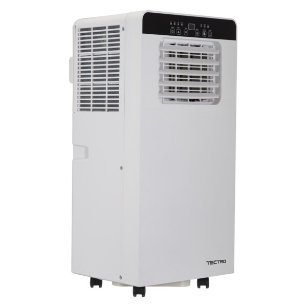
TP 4020 - Portable air conditioner TECTRO - Free user manual and instructions
Find the device manual for free TP 4020 TECTRO in PDF.


| Product type | Portable air conditioner |
| Brand | TECTRO |
| Model | TP 4020 |
| Dimensions (approx.) | 70 x 35 x 35 cm |
| Weight (approx.) | 25 kg |
| Power supply | 230 V / 50 Hz, grounded plug |
| Cooling power | 2.6 kW (for rooms up to 12 m²) |
| Refrigerant gas | R290 (flammable) |
| Main functions | Cooling, dehumidification, ventilation, air filtration |
| Operating modes | Cool mode, dehumidification mode, ventilation mode |
| Control | Control panel and remote control |
| Air exhaust | Requires exhaust hose to the outside |
| Water tank | Manual drainage via drain plug |
| Air filter | Washable, clean regularly |
| Supplied accessories | Exhaust hose, outdoor adapter (2x), remote control, water hose (for TPH 4026) |
| Safety | Grounding required, do not cover grilles, do not use extension cord |
| Maintenance | Clean filter, empty tank, tool-free defrosting |
| Repairability | Repairs by authorized technician only, sealed components |
| Warranty | Warranty void if instructions not followed |
Frequently Asked Questions - TP 4020 TECTRO
User questions about TP 4020 TECTRO
0 question about this device. Answer the ones you know or ask your own.
Ask a new question about this device
Download the instructions for your Portable air conditioner in PDF format for free! Find your manual TP 4020 - TECTRO and take your electronic device back in hand. On this page are published all the documents necessary for the use of your device. TP 4020 by TECTRO.
USER MANUAL TP 4020 TECTRO
natural_image
White TECTRO air conditioner unit with control panel and indicator lights (no visible text or symbols on device body)
| D | GEBRAUCHSANWEISUNG | 2 |
| E | INSTRUCCIONES DE USO | 22 |
| F | MANUEL D’UTILISATION | 40 |
| GB | OPERATING MANUAL | 58 |
| I | ISTRUZIONI D’USO | 74 |
| NL | GEBRUIKSAANWIJZING | 94 |
| P | MANUAL DE INSTRUÇÕES | 112 |
| SLO | PRIROČNIK ZA UPORABO | 130 |
WICHTIGE TEILE


natural_image
Simple line drawing of a wavy horizontal bar with a numbered label (12) pointing to the bottom center (no text or symbols on the bar itself)natural_image
Line drawing of an air conditioning unit with duct and fan (no text or symbols)
natural_image
Technical line drawing of a bolt and a bracket assembly (no text or symbols)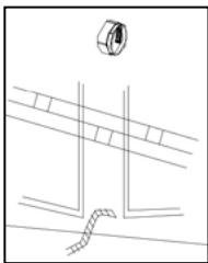
natural_image
Pure technical line drawing of a mechanical component or assembly without any text, numbers, or symbolsnatural_image
Illustration of a solar panel installation with grid connection and checkmark (no text or symbols)natural_image
Simple line drawing of a trash bin with no text or symbolsADVERTENCIA:
natural_image
Line drawing of a portable air conditioner unit with duct and fan (no text or symbols)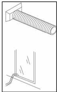
natural_image
Technical line drawing showing a bolt and a corner detail (no text or symbols)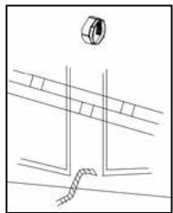
natural_image
Pure technical line drawing of a pipe or channel with no text, numbers, or symbolsREFRIGERACIÓN
natural_image
Illustration of a solar panel installation with a grid connection and checkmark (no text or symbols)natural_image
Line drawing of a portable air conditioner unit with duct and fan (no text or symbols)
natural_image
Technical line drawing of a bolt and a corner joint (no text or symbols)
natural_image
Pure technical line drawing of a mechanical component or fixture without any text, numbers, or symbolsREFROIDIR
natural_image
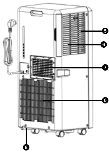
Illustration of a solar panel installation with a grid connection and checkmark (no text or symbols)1 Control panel
② Air outlet vent
③ Handle
4 Caster
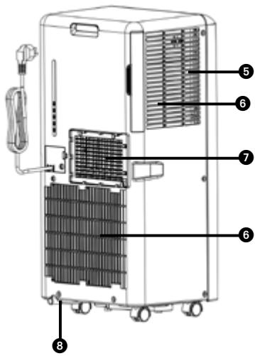
⑤ Air filter
6 Air inlet vent
⑦ Exhaust hose connector
8 Drain plug
⑨ Exhaust hose
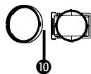
10 Adaptor to fit over the exhaust hose
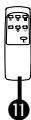
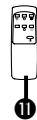
11 Remote control
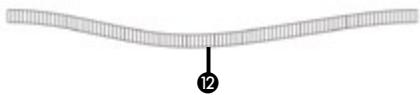
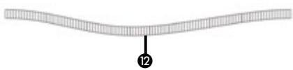
⑫ Water pipe (TPH 4026)

- READ THE DIRECTIONS FOR USE FIRST.
- IN CASE OF ANY DOUBT, CONTACT THIS DEALER.
Dear Sir, Madam,
Congratulations on the purchase of this appliance. This appliance has three functions in addition to cooling the air, namely, air dehumidification, circulation and filtration. The appliance is extremely easy to operate and move. You have acquired a high quality product that will provide you with many years of pleasure, on condition that you use it responsibly. Reading these instructions for use before operating this appliance will optimise its life span. We wish you coolness and comfort with your appliance.
Yours sincerely,
PVG Holding B.V.
Customer service department
A SAFETY INSTRUCTIONS
Read this user manual carefully before using the appliance and keep it for future reference. Install this appliance only when it complies with local/national legislation, ordinances and standards. This appliance is intended to be used as an air conditioner in residential houses and is only suitable for use in dry locations, in normal household conditions, indoors in living room, kitchen and garage.

IMPORTANT
- Never use the appliance with a damaged power cord, plug, cabinet or control panel. Never trap the power cord or allow it to come into contact with sharp edges.
- The installation must be completely in accordance with local regulations, ordinances and standards.
- The appliance is suitable exclusively for use in dry places, indoors.
- Check the mains voltage. This device is suitable exclusively for earthed sockets – connection voltage 220-240 Volt/ 50 Hz.
- The device MUST always have an earthed connection. You may absolutely not connect the appliance if the power supply is not earthed.
- The plug must always be easily accessible when the appliance is connected.
- Read these instructions carefully and follow the directions.
Before connecting the appliance, check that:
- The connection voltage corresponds to that on the type plate.
- The socket and power supply are suitable
for the appliance.
- The plug on the cable fits the socket.
- The appliance is on a stable and flat surface.
Have the electrical installation checked by a recognised expert if you are not sure that everything is in order.
- This appliance is a safe appliance, manufactured in accordance with CE safety standards. Nevertheless, as with every electrical appliance, exercise caution when using it.
- Never cover the air inlets and outlets.
- Empty the water reservoir through the water drain before moving it.
- Never allow the appliance to come into contact with chemicals.
- Do not insert objects into the openings of the device.
- Never allow the appliance to come into contact with water. Do not spray the appliance with water or submerge it as this may cause a short circuit.
- Always take the plug out of the socket before cleaning or replacing the appliance or a part of the appliance.
- NEVER connect the appliance with the aid of an extension cable. If a suitable, earthed socket is not available, have one fitted by a recognised electrician.
- Always consider the safety of children in the vicinity of this appliance, as with every electrical appliance.
- Always have any repairs – beyond regular maintenance – carried out by a recognised service engineer. Failure to do so may lead to invalidation of the guarantee.
• Always take the plug out of the socket
when the appliance is not in use.
- If the power cable is damaged it must be replaced by the manufacturer, its customer service department or persons with comparable qualifications in order to prevent danger.
- This appliance is not intended for use by persons (including children) with reduced physical, sensory or mental capabilities, or lack of experience and knowledge, unless they have been given supervision or instruction concerning use of the appliance by a person responsible for their safety.
- Children should be supervised to ensure that they do not play with the appliance.
- This appliance can be used by children aged from 8 years and above and persons with reduced physical, sensory or mental capabilities or lack of experience and knowledge if they have been given supervision or instruction concerning use of the appliance in a safe way and understand the hazards involved.
• Children shall not play with the appliance. - Cleaning and user maintenance shall not be made by children without supervision.

ATTENTION!
- Never seal the room - where this appliance will be used - completely airtight. This will prevent under pressure in this room. Under pressure can disrupt the safe operation of geysers, ventilation systems, ovens, etc.
- Failing to follow the instructions may lead to nullification of the guarantee on this appliance.
Specific information regarding appliances with R 290 refrigerant gas.
• Thoroughly read all of the warnings.
- When defrosting and cleaning the appliance, do not use any tools other than those recommended by the manufacturing company.
- The appliance must be placed in an area without any continuously sources of ignition (for example: open flames, gas or electrical appliances in operation).
- Do not puncture and do not burn.
- This appliance contains Y g (see rating label back of unit) of R290 refrigerant gas.
- R290 is a refrigerant gas that complies with the European directives on the environment. Do not puncture any part of the refrigerant circuit. Be aware the refrigerants may not contain an odour.
- If the appliance is installed, operated or stored in a nonventilated area, the room must be designed to prevent to the accumulation of refrigerant leaks resulting in a risk of fire or explosion due to ignition of the refrigerant caused by electric heaters, stoves, or other sources of ignition.
- The appliance must be stored in such a way as to prevent mechanical failure.
- Individuals who operate or work on the refrigerant circuit must have the appropriate certification issued by an accredited organization that ensures competence in handling refrigerants according to a specific evaluation recognized by associations in the industry.
- Repairs must be performed based on the recommendation from the manufacturing company.
Maintenance and repairs that require the assistance of other qualified personnel must be performed under the supervision of an individual specified in the use of flammable refrigerants.
Appliances shall be installed, operated and stored in a room with a floor area larger than X m 2 . The appliance shall be stored in a well-ventilated area where the room size corresponds to the room area as specified for operation.
| MODEL | X (M2) |
| 2kW | 4 |
| 2,6kW | 12 |
| >2,6kW | 15 |

TAKE NOTE OF FUSE SPECIFICATIONS
The air conditioner's circuit board (PCB) is designed with a fuse to provide overcurrent protection. The specifications of the fuse are printed on the circuit board, such as: T3.15AL/250VAC, T5AL/250VAC, T3.15A/250VAC, T5A/250VAC, T20A/250VAC, T30A/250VAC, etc.
NOTE: For the units using R32 or R290 refrigerant, only the blast-proof ceramic fuse can be used.
| Explanation of symbols displayed on the appliance (For the appliance adopts R32/R290 Refrigerant only): | |
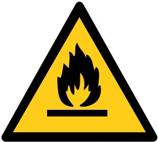 | WARNING:This symbol shows that this appliance used a flammable refrigerant. If the refrigerant is leaked and exposed to an external ignition source, there is a risk of fire. |
 | CAUTION:This symbol shows that the user manual should be read carefully. |
 | CAUTION:This symbol shows that the installation manual should be read carefully. |
 | CAUTION:This symbol shows that the technical manual should be read carefully. |
INSTRUCTIONS FOR REPAIRING APPLIANCES CONTAINING
R290
1 GENERAL INSTRUCTIONS
This instruction manual is intended for use by individuals possessing adequate backgrounds of electrical, electronic, refrigerant and mechanical experience.
1.1 Checks to the area
Prior to beginning work on systems containing flammable refrigerants, safety checks are necessary to ensure that the risk of ignition is minimised. For repair to the refrigerating system, the following precautions shall be complied with prior to conducting work on the system.
1.2 Work procedure
Work shall be undertaken under a controlled procedure so as to minimise the risk of a flammable gas or vapour being present while the work is being performed.
1.3 General work area
All maintenance staff and others working in the local area shall be instructed on the nature of work being carried out. Work in confined spaces shall be avoided. The area around the workspace shall be sectioned off. Ensure that the conditions within the area have been made safe by control of flammable material.
1.4 Checking for presence of refrigerant
The area shall be checked with an appropriate refrigerant detector prior to and during work, to ensure the technician is aware of potentially flammable atmospheres. Ensure that the leak detection equipment being used is suitable for use with flammable refrigerants, i.e. nonsparking, adequately sealed or intrinsically safe.
1.5 Presence of fire extinguisher
If any hotwork is to be conducted on the refrigeration equipment or any associated parts, appropriate fire extinguishing equipment shall be available to hand. Have a dry powder or CO2 fire extinguisher adjacent to the charging area.
1.6 No ignition sources
No person carrying out work in relation to a refrigeration system which involves exposing any pipe work that contains or has contained flammable refrigerant shall use any sources of ignition in such a manner that it may lead to the risk of fire or explosion. All possible ignition sources, including cigarette smoking, should be kept sufficiently far away from
the site of installation, repairing, removing and disposal, during which flammable refrigerant can possibly be released to the surrounding space. Prior to worktaking place, the area around the equipment is to be surveyed to make sure that there are no flammable hazards or ignition risks. "No Smoking" signs shall be displayed.
1.7 Ventilated area
Ensure that the area is in the open or that it is adequately ventilated before breaking into the system or conducting any hot work. A degree of ventilation shall continue during the period that the work is carried out. The ventilation should safely disperse any released refrigerant and preferably expel it externally into the atmosphere.
1.8 Checks to the refrigeration equipment
Where electrical components are being changed, they shall be fit for the purpose and to the correct specification. At all times the manufacturer's maintenance and service guidelines shall be followed. If in doubt consult the manufacturer's technical department for assistance. The following checks shall be applied to installations using flammable refrigerants: - the charge size is in accordance with the room size within which the refrigerant containing parts are installed;
- the ventilation machinery and outlets are operating adequately and are not obstructed;
- if an indirect refrigerating circuit is being used, the secondary circuit shall be checked for the presence of refrigerant;
- marking to the equipment continues to be visible and legible. Markings and signs that are illegible shall be corrected;
- refrigeration pipe or components are installed in a position where they are unlikely to be exposed to any substance which may corrode refrigerant containing components, unless the components are constructed of materials which are inherently resistant to being corroded or are suitably protected against being so corroded.
1. 9 Checks to electrical devices
Repair and maintenance to electrical components shall include initial safety checks and component inspection procedures. If a fault exists that could compromise safety, then no electrical supply shall be connected to the circuit until it is satisfactorily dealt with. If the fault cannot be corrected immediately but it is necessary to continue operation, an adequate temporary solution shall be used. This shall be reported to the owner of the equipment so all parties are advised. Initial safety checks shall include:
- that capacitors are discharged: this shall be done in a safe manner to avoid possibility of sparking;
- that there no live electrical components and wiring are exposed while charging, recovering or purging the system;
- that there is continuity of earth bonding.
2 REPAIRS TO SEALED COMPONENTS
2.1 During repairs to sealed components, all electrical supplies shall be disconnected from the equipment being worked upon prior to any removal of sealed covers, etc. If it is absolutely necessary to have an electrical supply to equipment during servicing, then a permanently operating form of leak detection shall be located at the most critical point to warn of a potentially hazardous situation.
2.2 Particular attention shall be paid to the following to ensure that by working on electrical components, the casing is not altered in such a way that the level of protection is affected. This shall include damage to cables, excessive number of connections, terminals not made to original specification, damage to seals, incorrect fitting of glands, etc.
Ensure that the apparatus is mounted securely.
Ensure that seals or sealing materials have not degraded such that they no longer serve the purpose of preventing the ingress of flammable atmospheres. Replacement parts shall be in accordance with the manufacturer's specifications.
NOTE The use of silicon sealant may inhibit the effectiveness of some types of leak detection equipment. Intrinsically safe components do not have to be isolated prior to working on them.
3 REPAIR TO INTRINSICALLY SAFE COMPONENTS
Do not apply any permanent inductive or capacitance loads to the circuit without ensuring that this will not exceed the permissible voltage and current permitted for the equipment in use. Intrinsically safe components are the only types that can be worked on while live in the presence of a flammable atmosphere. The test apparatus shall be at the correct rating.
Replace components only with parts specified by the manufacturer. Other parts may result in the ignition of refrigerant in the atmosphere from a leak.
4 CABLING
Check that cabling will not be subject to wear, corrosion, excessive pressure, vibration, sharp edges or any other adverse environmental effects. The check shall also take into account the effects of aging or continua! vibration from sources such as compressors or fans.
5 DETECTION OF FLAMMABLE REFRIGERANTS
Under no circumstances shall potential sources of ignition be used in the searching for or detection of refrigerant leaks. A halide torch (or any other detector using a naked flame) shall not be used.
6 LEAK DETECTION METHODS
The following leak detection methods are deemed acceptable for systems containing flammable refrigerants. Electronic leak detectors shall be used to detect flammable refrigerants, but the sensitivity may not be adequate, or may need recalibration. (Detection equipment shall be calibrated in a refrigerant-free area.)
Ensure that the detector is not a potential source of ignition and is suitable for the refrigerant used. Leak detection equipment shall be set at a percentage of the LFL of the refrigerant and shall be calibrated to the refrigerant employed and the appropriate percentage of gas (25 % maximum) is confirmed.
Leak detection fluids are suitable for use with most refrigerants but the use of detergents containing chlorine shall be avoided as the chlorine may react with the refrigerant and corrode the copper pipework.
If a leak is suspected, all open flames shall be removed/extinguished.
If a leakage of refrigerant is found which requires brazing, all of the
refrigerant shall be recovered from the system, or isolated (by means of shut off valves) in a part of the system remote from the leak. Oxygen free nitrogen (OFN) shall then be purged through the system both before and during the brazing process.
7 REMOVAL AND EVACUATION
When breaking into the refrigerant circuit to make repairs - or for any other purpose - conventional procedures shall be used. However, it is important that best practice is followed since flammability is a consideration. The following procedure shall be adhered to: remove refrigerant; purge the circuit with inert gas; evacuate; purge again with inert gas; open the circuit by cutting or brazing.
The refrigerant charge shall be recovered into the correct recovery cylinders. The system shall be "flushed" with OFN to render the unit safe. This process may need to be repeated several times. Compressed air or oxygen shall not be used for this task. Flushing shall be achieved by breaking the vacuum in the system with OFN and continuing to fill until the working pressure is achieved, then venting to atmosphere, and finally pulling down to a vacuum. This process shall be repeated until no refrigerant is within the system.
When the final OFN charge is used, the system shall be vented down to atmospheric pressure to enable work to take place. This operation is absolutely vital if brazing operations on the pipework are to take place. Ensure that the outlet for the vacuum pump is not close to any ignition sources and there is ventilation available.
8 CHARGING PROCEDURES
In addition to conventional charging procedures, the following requirements shall be followed. Ensure that contamination of different refrigerants does not occur when using charging equipment. Hoses or lines shall be as short as possible to minimise the amount of refrigerant contained in them. Cylinders shall be kept upright. Ensure that the refrigeration system is earthed prior to charging the system with refrigerant. Label the system when charging is complete (if not already). Extreme care shall be taken not to overfill the refrigeration system. Prior to recharging the system it shall be pressure tested with OFN. The system shall be leak tested on completion of charging but prior to commissioning. A follow up leak test shall be carried out prior to leaving the site.
9 DECOMMISSIONING
Before carrying out this procedure, it is essential that the technician is completely familiar with the equipment and all its detail. It is recommended good practice that all refrigerants are recovered safely. Prior to the task being carried out, an oil and refrigerant sample shall be taken in case analysis is required prior to re-use of
reclaimed refrigerant. It is essential that 4 GB electrical power is available before the task is commenced.
a) Become familiar with the equipment and its operation.
b) Isolate system electrically.
c) Before attempting the procedure ensure that: mechanical handling equipment is available, if required, for handling refrigerant cylinders;
d) All personal protective equipment is available and being used correctly; the recovery process is supervised at all times by a competent person;
e) recovery equipment and cylinders conform to the appropriate standards.
f) Pump down refrigerant system, if possible. g) If a vacuum is not possible, make a manifold so that refrigerant can be removed from various parts of the system. h) Make sure that cylinder is situated on the scales before recovery takes place.
i) Start the recovery machine and operate in accordance with manufacturer's instructions.
j) Do not overfill cylinders. (No more than 80 % volume liquid charge).
k) Do not exceed the maximum working pressure of the cylinder, even temporarily.
I) When the cylinders have been filled correctly and the process completed, make sure that the cylinders and the equipment are removed from site promptly and all isolation valves on the equipment are closed off. m) Recovered refrigerant shall not be charged into another refrigeration system unless it has been cleaned and checked.
10 LABELLING
Equipment shall be labelled stating that it has been de-commissioned and emptied of refrigerant. The label shall be dated and signed. Ensure that there are labels on the equipment stating the equipment contains flammable refrigerant.

11 RECOVERY
When removing refrigerant from a system, either for servicing or decommissioning, it is recommended good practice that all refrigerants are removed safely. When transferring refrigerant into cylinders, ensure that only appropriate refrigerant recovery cylinders are employed. Ensure that the correct number of cylinders for holding the total system charge are available. All cylinders to be used are designated for the recovered refrigerant and labelled for that refrigerant (i.e. special cylinders for the recovery of refrigerant). Cylinders shall be complete with pressure relief valve and associated shut-off valves in good working order. Empty recovery cylinders are evacuated and, if possible, cooled before recovery occurs.
The recovery equipment shall be in good working order with a set of instructions concerning the equipment that is at hand and shall be suitable for the recovery of flammable refrigerants. In addition, a set of calibrated weighing scales shall be available and in good working order. Hoses shall be complete with leak-free disconnect couplings and in good condition. Before using the recovery machine, check that il is in satisfactory working order, has been properly maintained and that any associated electrical components are sealed to prevent ignition in the event of a refrigerant release. Consult manufacturer if in doubt.
The recovered refrigerant shall be returned to the refrigerant supplier in the correct recovery cylinder, and the relevant Waste Transfer Note arranged. Do not mix refrigerants in recovery appliances and especially not in cylinders.
If compressors or compressor oils are to be removed, ensure that they have been evacuated to an acceptable level to make certain that flammable refrigerant does not remain within the lubricant. The evacuation process shall be carried out prior to returning the compressor to the suppliers. Only electric healing to the compressor body shall be employed to accelerate this process. When oil is drained from a system, it shall be carried out safely.
B INSTALLATION

WARNING
Before using the appliance it should be left in an upright position for at least 2 hours.
This appliance is portable and can easily be moved from one room to another. In doing so keep this in mind:
1 Ensure that the appliance is positioned upright and on a level surface.
2 Do not operate the appliance inside the bathroom, shower, or in any other very humid environment.
3 Please keep a distance of 50 cm between the appliance and the wall or other objects to ensure proper air circulation.
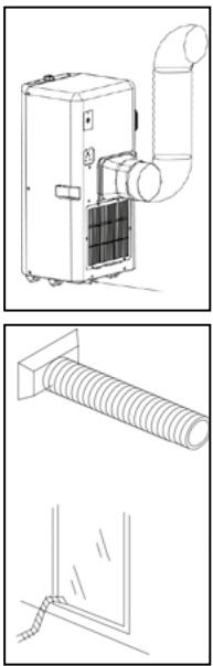
4 One end of the hose ⑩ must be attached to the air outlet ⑦ at the back of the appliance.
5 Ensure that the window air outlet ⑨ has a free flow outside. Close the window or door as much as possible to prevent outside air from entering

IMPORTANT
The flexible exhaust hose ⑨ should be less than 1m during operation, which provides the best performance. This length has been designed especially according to the specifications of the appliance. Do not use an extension or exchange for a different hose as that may lead to malfunctioning. The exhaust air must flow freely, any blockage can lead to overheating of the appliance. Take care to prevent any bow or bend in the exhaust hose.
natural_image
Technical line drawings of air ducts and connectors (no text or symbols)
C OPERATION

- Display
- On / Off button
- Increase temperature control
- Decrease temperature control
- Mode control
- Fan speed control
- Timer control
- Cooling mode indicator
- Dehumidifier mode indicator
- Air circulation mode indicator
- Heating mode indicator (TPH 4026)
- Reservoir full indicator
- High fan speed indicator
- Low fan speed indicator
- Timer setting indicator
- Remote control receiver
1 Insert the plug into the wall outlet.
2 Press the ⏻-button ② to switch on the appliance.
- If the ambient temperature is higher than 25irc C, the appliance will work in cooling mode.
- If the ambient temperature is < 25ircC , the appliance will work in air circulation mode.
3 With Ⓞ-button 5 you can change the operating mode of the unit.
By pressing the Ⓞ-button the following modes appear:


COOLING
When the appliance is in the cooling mode, the following functions apply:
- The fan speed can be adjusted by pressing the Ⓧ-button 6

- The temperature can be set by pressing the ③ and ④ buttons, anywhere between 16°C en 31°C. After flashing 4 times the current room temperature is shown. In automatic mode the appliance selects the fan speed based on the room temperature. The speed cannot be adjusted.
HEATING (TPH 4026)
When the appliance is in the heating mode, the following functions apply: GB
GB
- The fan speed can be adjusted by pressing the ⚙-button 6
Maximum setting 13
✗ Lowest setting 14
- The temperature can be set by pressing the ③ ▲ and ④ ▼ buttons, anywhere between 16°C en 31°C. After flashing 4 times the current room temperature is shown. In automatic mode the appliance selects the fan speed based on the room temperature. The speed cannot be adjusted.

It depends on the environment whether the required temperature will be reached. It is not a malfunction of the appliance if the room temperature remains above the "set temp". It could well be that the heat load of the room is too much.
DEHUMIDIFYING
The air can also be de-humidified with this appliance:
-
Select the dehumidifying function ⚠⑨ with the mode Ⓞ⑤ button
-
Do not connect the de-aeration hose
-
Connect a fixed water drainage hose (not included) and lead the hose to a water drain. Ensure that the water drainage hose runs downhill for its entire length.
The appliance will now de-humidify as long as the room temperature is above the set value. The appliance will be unable to de-humidify if the room temperature drops below the set value.
AIR CIRCULATION
In this mode the appliance only circulates air; the appliance will not cool or dehumidify. The air is filtered.
When the unit is in this mode, the following functions apply:
- The fan speed can be adjusted by pressing the Ⓧ6-button
Maximum setting 13
✗ Lowest setting 14
4 When the unit is switched off the most recent setting will be stored in memory.
5 The timer function allows you to switch the unit on or off at a certain time.
-
Press TIMER button to set the operating hours you desired and the buttons ▲ ③ and ▼ ④ (1 to 24 hours, the timer indicator will light on). When the set time has been reached, the machine will turn off automatically. The display window will show the hour(s) you set as you press TIMER button. If the timer button is not pressed, the unit will work continuously.
-
By pressing the timer but without turning on the other functions, you can PRE-SET the time for the machine to work. For example, if you press the timer to '2', the unit will work automatically after 2 hours.

NOTE!
The compressor has been set so that it starts functioning three minutes after the (re)start of the air conditioner. The cooling will switch off when the room temperature is lower than the set temperature. Air circulation will however continue to work on the set level. When the room temperature rises above the set temperature, the cooling will work again.
REMOTE CONTROL
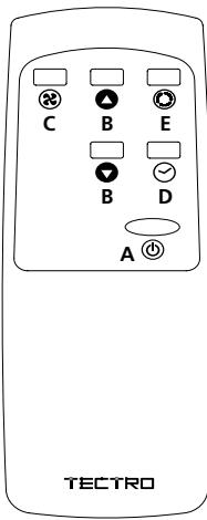
a. Power on/off button
b. Temperature +/- buttons
c. Fan Speed button
d. Timer button
e. Function button
The remote control works in combination with the control panel. Aim the front end of the remote control at the control panel. The maximum operating distance from the air conditioner is approximately 5 metres. Place 2 pieces of 2xAAA type 1,5 V batteries before use (not included).
D AIR FILTER
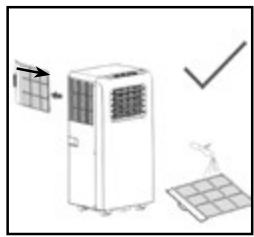
The appliance is equipped with a screen filter to remove the bigger dust particles.
The screen filter has to be cleaned 2x a week. Clean the air filter with a neutral detergent in lukewarm water (40°C) and allow to dry slowly.
To take out and place back the screen filter, see picture at the side.

NOTE!
- Never use the appliance without the air filter.
E AIR FLOW
Move the air vent directly to adjust the air flow direction of the louvres.
F EMPTY INTERNAL WATER CONTAINER
Under extreme (environmental) circumstances it may be necessary to empty the internal water container regularly. When the internal water container is full the ⑫ light will flash and the display shows E2. Touch any button to stop the beeping. The unit will switch off automatically. To empty the water container do the following:
1 Do not move the unit. Drastic movements can cause water leakage.
2 Switch off the unit and remove the plug from the wall outlet.
3 Place a pan or appropriate tray on the floor underneath the drain hole.
4 Remove the drain knob and rubber plug 8 from the drain tube and let the water run out. (± 0.8 litres).
5 Replace the rubber plug ⑧ and the drain knob and switch on the unit. The warning light Ⓦ ⑫ should be off and E2 disappears.

NOTE!
When the air conditioner is in use, under normal circumstances the condensed water will be drained through the air outlet-tube.
DEHUMIDIFICATION
If the unit will be used mainly as dehumidifier, do not connect the exhaust hose ⑨ and let the warm air return in the room. Continuous drainage is then necessary and more efficient. You must, however, use a water drain tube, placing its discharge end at a suitable drainage point.
natural_image
Illustration of a solar panel installation with a control panel and checkmark (no text or symbols)G MAINTENANCE

WARNING!
Switch off the unit and remove the electrical plug from the mains before cleaning the appliance or filter, or before replacing the filters.
Clean the housing with a soft, damp cloth. Never use aggressive chemicals, petrol, detergents or other cleansing solutions. For maintenance of the filters, refer to Chapter D "Air Filter".

NOTE!
Never use the air conditioner without screenfilter.
H STORAGE
1 Empty the internal water container (refer to Chapter F)
2 Clean and replace the filter (see also chapter D).
3 Put the unit in air circulation mode for 2 hours to ensure that the inside becomes completely dry.
4 Protect the unit against dust and store it in a dry place.
I TROUBLE SHOOTING
| Problem | Cause | Solution |
| Unit does not start when pressing on/off button | Water full indicator lamp blinks, and water tray is full | Dump the water out of the water tray |
| Room temperature is higher than the setting temperature. (Electric heating mode) | Reset the temperature | |
| Room temperature is lower than the setting temperature. (Cooling mode) | Reset the temperature | |
| Not cool enough | The doors or windows are not closed. | Make sure all the windows and doors are closed. |
| There are heat sources inside the room. | Remove the heat sources if possible | |
| Exhaust air hose is not connected or blocked. | Connect or clean the exhaust air hose. | |
| Temperature setting is too high. | Reset the temperature | |
| Air inlet is blocked. | Clean the air inlet. | |
| Noisy | The ground is not level or not flat enough | Place the unit on a flat, level ground if possible |
| The sound comes from the flowing of the refrigerant inside the air conditioner | It is normal. | |
| E0 Code | Room temperature sensor failed | Replace room temperature sensor (the unit can also work without replacement.) |
| E1 Code | Condenser temperature sensor failed | Replace condenser temperature sensor |
| E2 Code | Water tray full when cooling | Take off rubber stopper and empty the water. |
| E3 Code | Evaporator temperature sensor failed | Replace evaporator temperature sensor |
| E4 Code | Water tray full when heating | Please empty the water tray. |

natural_image
Simple line drawing of a trash bin with no text or symbolsNever try to repair or dismantle the air conditioner yourself. Incompetent repairs result in loss of warranty and can endanger the user.
J WASTE DISPOSAL
Do not dispose of electrical appliances as unsorted municipal waste, use separate collection facilities. Contact your local government for information regarding the collection systems available. If electrical appliances are disposed of in landfills or dumps, hazardous substances can leak into the groundwater and get into the food chain, damaging your health and well-being. When replacing old appliances with new once, the retailer is legally obligated to take back your old appliance for disposal at least for free of charge. Do not throw batteries into the fire, where they can explode or release dangerous liquids. If you replace or destroy the remote control, remove the batteries and throw them away in accordance with the applicable regulations because they are harmful to the environment. GB
COMPONENTI PRINCIPALI


natural_image
Simple line drawing of a wavy horizontal bar with a numbered label (12) pointing to the bottom edge.- LEGGERE DAPPRIMA LE ISTRUZIONI D'USO.
- IN CASO DI DUBBIO, RIVOLGERSI AL RIVENDITORE.
natural_image
Illustration of a solar panel installation with grid connection and checkmark (no text or symbols)TELECOMANDO
GUIDA ALLA RICERCA GUASTI
natural_image
Pure electrical circuit lines without any symbolsWAARSCHUWING:
natural_image
Technical line drawings of air ducts and pipe fittings (no text or symbols)Koelen 8
Ontvochtigen 9
Lucht circuleren 10
Verwarming (TPH 4026) 11
KOELEN
natural_image
Illustration of a portable air conditioner unit with grid airflow and a checkmark indicating inspection (no text or symbols)natural_image
Simple line drawing of a trash bin with no text or symbolsAFVALVERWERKING


natural_image
Simple line drawing of a wavy horizontal bar with a numbered label (12) pointing to the middle bar (no text or symbols beyond the label)- LEIA AS INSTRUÇÕES DE UTILIZAÇÃO PRIMEIRO.
- EM CASO DE DÚVIDA, ENTRE EM CONTACTO COM O REVENDEDOR.
Caro utilizador,
natural_image
Line drawing of a portable air conditioner unit with duct and fan (no text or symbols)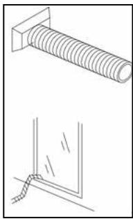
natural_image
Technical line drawing showing a bolt and a corner detail (no text or symbols)
natural_image
Pure technical line drawing of a pipe or duct system without any text, numbers, or symbolsREFRIGERAÇÃO
natural_image
Illustration of a solar panel installation with a grid connection and checkmark (no text or symbols)natural_image
Pure line drawing of a trash bin with no text or symbolsnatural_image
Line drawing of a portable air conditioner unit with duct and fan (no text or symbols)
natural_image
Technical line drawing of a bolt and a corner detail (no text or symbols)
natural_image
Pure technical line drawing of a pipe or conduit with no text, numbers, or symbolsHLAJENJE
natural_image
Illustration of a solar air conditioner unit with a grid panel and a checkmark indicating inspection (no text or symbols)Distributed in Europe by PVG Holding B.V.
Benötigen Sie weitere Informationen oder treten Probleme auf, besuchen Sie bitte unsere Website www.pvg.eu, oder setzen Sie sich mit unserem Kundendienst in Verbindung (T: +31 412 694 694).
© For alle yderligere oplysninger eller ved eventuelle problemer med apparatet henvises til www.pvg.eu eller det lokale Kundecenter (T: +45 77 34 33 30).
(ES) Si necesita información o si tiene algún problema, visite nuestra página Web www.pvg.eu, o póngase en contacto con el servicio cliente (T: +34 916 113 113).
F Si vous souhaitez obtenir des informations supplémentaires ou si vous rencontrez un problème, rendez-vous sur notre site Web (www.pvg.eu) ou contactez notre service client (T : +33 2 32 96 07 47 / +32 (0)3 326 39 39).
FIN Jos haluat huoltoapua, lisätietoja tai laitteen kanssa tulee ongelmia, tutustu verkkosivustoon osoitteessa www.pvg.eu tai kysy neuvoa PVG kuluttajapalvelukeskuksesta (T: +45 77 34 33 30).
GB If you need information or if you have a problem, please visit the our website (www.pvg.eu) or contact our sales support (T: +31 412 694 694).
① Per informazioni e in caso di problemi, visitate il sito Web www.pvg.eu oppure contattate il Centro Assistenza Clienti (T: +39 0571 628 500).
Hvis du trenger informasjon, eller hvis du har et problem med produktet, kan du gå til nettsidene www.pvg.eu. Alternativt kan du kontakte med PVG' forbrukertjeneste (T: +45 77 34 33 30).
NL Als u informatie nodig hebt of als u een probleem hebt, bezoek dan de onze website (www.pvg.eu) of neem contact op met de afdeling sales support (T: +31 412 694 694 / +32 (0)3 326 39 39).
Se necessitar de informações ou se tiver problemas, visite o Web site www.pvg.eu ou contacte o Centro de Assistência (T: +34 916 113 113).
PL W przypadku problemów i w celu uzyskania szczegółowych informacji odwiedź stronę internetową Qlima dostępną pod adresem www.pvg.eu lub skontaktuj się z Centrum kontaktów Qlima (T: +48 48 613 00 70)
⑤ Om du behöver service eller information eller har problem med apparaten kan du besöka www.pvg.eu eller kontakta Qlima kundtjänst (T: +45 77 34 33 30).
SLO Če želite dodatne informacije, obiščite spletno mesto podjetja na naslovu www.pvg.eu ali pokličite na telefonsko (T: +386 (0)41 674 139).

- WICHTIGE TEILE
- ADVERTENCIA:
- REFRIGERACIÓN
- REFROIDIR
- A SAFETY INSTRUCTIONS
- IMPORTANT
- ATTENTION!
- TAKE NOTE OF FUSE SPECIFICATIONS
- INSTRUCTIONS FOR REPAIRING APPLIANCES CONTAINING
- R290
- GENERAL INSTRUCTIONS
- Checks to the area
- Work procedure
- General work area
- Checking for presence of refrigerant
- Presence of fire extinguisher
- No ignition sources
- Ventilated area
- Checks to the refrigeration equipment
- 9 Checks to electrical devices
- REPAIRS TO SEALED COMPONENTS
- REPAIR TO INTRINSICALLY SAFE COMPONENTS
- CABLING
- DETECTION OF FLAMMABLE REFRIGERANTS
- LEAK DETECTION METHODS
- REMOVAL AND EVACUATION
- CHARGING PROCEDURES
- DECOMMISSIONING
- LABELLING
- RECOVERY
- B INSTALLATION
- WARNING
- C OPERATION
- COOLING
- HEATING (TPH 4026)
- DEHUMIDIFYING
- AIR CIRCULATION
- NOTE!
- REMOTE CONTROL
- D AIR FILTER
- E AIR FLOW
- F EMPTY INTERNAL WATER CONTAINER
- DEHUMIDIFICATION
- G MAINTENANCE
- WARNING!
- H STORAGE
- J WASTE DISPOSAL
- COMPONENTI PRINCIPALI
- TELECOMANDO
- WAARSCHUWING:
- Koelen 8
- KOELEN
- AFVALVERWERKING
- REFRIGERAÇÃO
- HLAJENJE
- Distributed in Europe by PVG Holding B.V.
Brand : TECTRO
Model : TP 4020
Category : Portable air conditioner