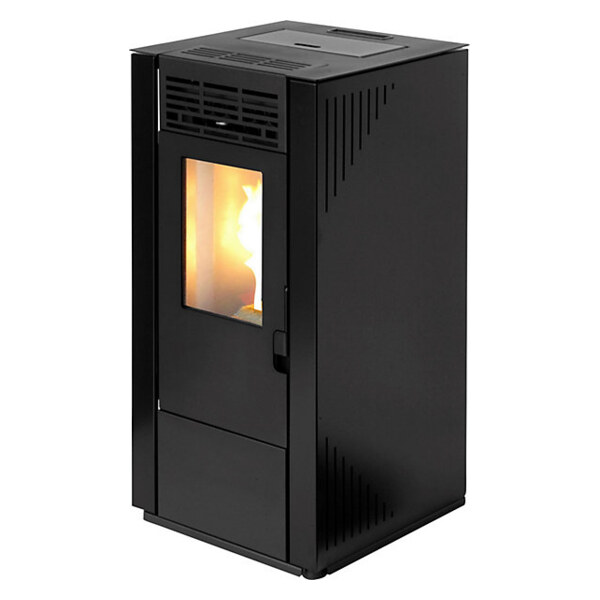
TBH-570-3 - Pellet stove TECTRO - Free user manual and instructions
Find the device manual for free TBH-570-3 TECTRO in PDF.


| Brand | TECTRO |
| Model | TBH-570-3 |
| Product type | Wood pellet stove |
| Energy efficiency class | A+ |
| Nominal thermal power | 7.8 kW |
| Energy efficiency | 90.2% (nominal) / 91.3% (reduced) |
| Energy efficiency index | 126 |
| Recommended fuel | Wood pellets DIN+/Önorm+/EN+, diameter 6 mm, length 30 mm |
| Hopper capacity | 13 kg |
| Autonomy | 7 to 18 hours (depending on power) |
| Power consumption | 300 W (nominal) / 100 W (reduced) |
| Supply voltage | 230 V / ~50 Hz |
| Flue pipe diameter | 80 mm (max 150 mm allowed) |
| Required draft | 10 Pa |
| Net weight | 77 kg |
| Flue gas temperature (nominal/reduced) | 135 °C / 84.4 °C |
| CO emissions (13% O2, nominal) | 0.005% (12 mg/Nm³) |
| Primary air inlet | Yes |
| Recirculation fan | Yes |
| Installation type | Floor-standing, not built-in |
| Control screen | Yes, with connection cable |
| Safety devices | Safety thermostat, differential pressure switch, ambient and flue temperature sensors |
| Warranty | Subject to installation by a certified professional |
Frequently Asked Questions - TBH-570-3 TECTRO
User questions about TBH-570-3 TECTRO
0 question about this device. Answer the ones you know or ask your own.
Ask a new question about this device
Download the instructions for your Pellet stove in PDF format for free! Find your manual TBH-570-3 - TECTRO and take your electronic device back in hand. On this page are published all the documents necessary for the use of your device. TBH-570-3 by TECTRO.
USER MANUAL TBH-570-3 TECTRO
natural_image
Black industrial stove unit with ventilation grilles and a single glass door (no visible text or symbols)| F | MANUEL D'INSTALLATION | 2 |
| E | MANUAL DE INSTALACIÓN | 22 |
| G | ΟΔΗΓΟΣ ΕΓΚΑΤΑΣΤΑΣΗΣ | 40 |
| GB | INSTALLATION MANUAL | 60 |
| I | MANUELE DI INSTALLAZIONE | 78 |
| NL | INSTALLATIEHANDLEIDING | 96 |
- AVANT-PROPOS
- CONSIGNES DE SÉCURITÉ
- INSTRUCTIONS DE MONTAGE DES ÉLÉMENTS FOURNIS
B JE NE DISPOSE PAS D'UNE ARRIVÉE D'AIR INDÉPENDANTE
- INTRODUCTION
- SAFETY INSTRUCTIONS
- INSTALLATION INSTRUCTIONS FOR INCLUDED PARTS
3.1 Installing the display (unless already installed at the factory)
3.2 Installing the room temperature sensor
- MINIMUM REQUIREMENTS FOR THE FLUE/CHIMNEY
4.1 Minimum requirements that the chimney must meet - CONNECTION POINT OF THE CHIMNEY TO THE APPLIANCE
- CONNECTING THE COMBUSTION AIR PIPE
- REQUIRED VENTILATION OF THE ROOM WHEN THE APPLIANCE IS IN USE
- PLACING THE APPLIANCE
- ELECTRICAL CONNECTION
9.1 Electrical diagram
- FIRST USE
- PRODUCT FICHE

This installation manual is intended for use by persons with sufficient knowledge of electrical engineering, mechanical engineering and combustion technology. Please note: incorrect and/or improper installation of the stove can result in serious physical injury and/or damage to property.
Damage caused by incorrect/inaccurate installation and/or failure to follow the advice in this manual is not covered by the warranty. Neither the manufacturer nor the distributor are responsible for the interpretation of this information and accept no liability whatsoever in connection with its use.
Due to technical improvements, data, specifications and paramete are subject to change without prior notice. The correct specifications are listed on the type plate.
The appliance must be installed by a certified installer. Only then can the end user be sure that the installer has sufficient expertise and product knowledge.
The appliance will only operate safely if it is connected to a professionally installed, properly functioning chimney/flue. The chimney/flue must always be installed in accordance with local regulations and/or the requirements of the insurer and/or the instructions in this manual. The most stringent regulations prevail.
Even when installed with a proper chimney/flue and a direct fresh air supply to the appliance, the appliance can never be considered a room-independent combustion system.
The images in this manual are for illustration and explanation purposes only and may differ from the appliance that is purchased.
2. SAFETY INSTRUCTIONS:

PLEASE NOTE! All images in this manual and on the packaging are for illustrative purposes only and may differ slightly from the appliance you have purchased. Only the actual design is important.

Failure to follow the requirements set out in this manual could lead to dangerous situations and will void the warranty.
Only install this appliance if it complies with local/national legislation, regulations and standards. This appliance is intended for heating rooms in homesand is only suitable for indoor use in living rooms, kitchens and garages in drylocations in normal domestic situations. Do not install the appliance in bedrooms or bathrooms.
The correct installation of this appliance is extremely important for the proper functioning of the product and for your personal safety. Therefore, the following instructions apply:
- This appliance must be installed by an authorised heating or installation engineer, otherwise the warranty will be invalidated. If the instructions provided in this manual deviate from local and/or regional legislation, the strictest conditions must be applied. The manufacturer and distributor expressly disclaim all responsibility in the event that the installation does not comply with local laws and regulations and/or in the event of incorrect ventilation and/or incorrect use.
• The appliance may only be installed in a
room whose location, construction and use do not prevent the safe use of the appliance.
- The following explanation of options regarding chimney installation and/or fresh air supply are only indicative. You are responsible for ensuring that it is installed in accordance with national and/or local rules and/or regulations. You should also follow the regulations of your insurer and/or the regulations of your chimney supplier. The strictest rules and regulations will then apply. A qualified installer is required to prevent errors in the installation and to guarantee proper functioning of the system. Errors, damages and warranty claims resulting from the failure to use a qualified installer are not covered by the warranty.
In case of any problem with this appliance or if you have any difficulty reading or do not (fully) understand this manual, always contact the dealer or installer directly.
- Oxygen, and therefore air, is required to burn pellets.

Ensure that the combustion air duct can draw in fresh air from outside at all times.
- Never cover air inlets and outlets and regularly check that the air inlet is free of contamination.
- Transport the appliance using the correct equipment. Failure to use the correct
equipment may result in personal injury and/or damage to the appliance.
- Do not place flammable objects and/or materials within 200 mm of the sides and 200 mm from the rear of the appliance or within 800 mm of the front of the appliance.
- The appliance is designed for freestanding installation and is not suitable for built-in installation. Maintain a clearance of 200 mm between the walls and the sides/rear of the appliance.
- During use, the appliance can become very hot on the outside. NEVER leave children unattended near the appliance. Supervise children to prevent them from playing with the appliance.
- This appliance is not intended for use by persons (including children) with limited physical, sensory or mental abilities, or with insufficient experience and knowledge, unless they are supervised or have received instructions regarding the use of the appliance from a person responsible for their safety. Never leave the above-mentioned persons near the packaging. There is a risk of suffocation from the packaging material.
- Children under the age of 3 must be kept away from the appliance unless they are under constant supervision.
- Children aged from 3 years and less than 8 years shall only switch on/off the appliance provided that it has been placed or installed in its intended normal operating position and they have been given supervision or instruction concerning use of the appliance in a safe way and understand the ha-
zards involved. Children aged from 3 years and less than 8 years shall not plug in, regulate and clean the appliance or perform user maintenance.
- During use, the outside of the appliance can become very hot. Use suitable, heat-resistant personal protective equipment such as heat-resistant gloves when operating the appliance.
- Always use the necessary personal protective equipment, such as safety goggles, gloves, etc., when installing and maintaining the appliance.
- Be careful with flammable fabrics; it can catch fire if you get too close to the fire in the appliance.
- Do not work with flammable solvents in the same room where the appliance is burning. Avoid risks; remove flammable solvents and other flammable materials from the room.
- The appliance is heavy; have the strength of the floor checked by an authorised expert.
- Do not use any fuel other than the specified wood pellets. Other fuels such as - wood waste containing glue and/or solvents, - waste wood in general, - cardboard, - liquid fuel, - alcohol, - petroleum, - petrol, - waste material or rubbish, etc. are prohibited.
- Poor quality, wet, impregnated or painted fuel leads to the formation of condensation and/or soot in the chimney or in the appliance. This leads to reduced performance and potentially dangerous situations.
• Have the chimney cleaned and swept re-
gularly in accordance with local laws and regulations and/or as prescribed by your insurance company. In the absence of local laws and regulations and/or insurance requirements, have your entire appliance system (including the chimney) checked and maintained at least twice a year (the first time at the beginning of the heating season) — including the chimney — by an authorised specialist at least twice a year (the first time at the start of the heating season). If the appliance is used intensively, the entire system, including the chimney, must be cleaned more often.
- Do not use the appliance as a barbecue.

Only connect one pellet heater per flue. Connecting multiple pellet stoves to the same flue can lead to dangerous situations.
This appliance also requires an electrical power supply. Be sure to read the following cautions and notes carefully:
- Do not use a damaged power cord.
- The appliance shall not be used if the seals around the door are damaged.
- If the power cord is damaged, it must be replaced by the manufacturer, its customer service department or persons with similar qualifications to prevent hazards.
- Do not clamp or bend the cord.
- Ensure that the power cord does not touch hot parts of the appliance.
- NEVER connect the appliance using an extension cord. If no suitable, earthed socket is available, have one installed by a quali-
fied electrician.
- Check the mains voltage. This device is only suitable for earthed sockets - Connection voltage 230 Volt/ \~50 Hz.

The appliance MUST always have an earthed connection. If the power supply is not earthed, you must NOT connect the appliance under any circumstances.
- The plug must always be easily accessible when the appliance is connected.
- Do not place the appliance directly under a wall socket.
Before connecting the appliance, check that:
- The connection voltage corresponds to the value on the type plate.
- The socket and power supply are suitable for the appliance.
• The plug on the cable fits into the socket.
• The appliance is properly earthed.

Have the electrical installation checked by a qualified expert if you are not sure whether everything is in order.
- Have the electrical installation checked by a qualified expert if you are not sure whether everything is in order.
- Do not insert objects into the openings of the appliance.
- Never allow the appliance to come into contact with water. Never spray water over the appliance or immerse it in water, as this may cause a short circuit.
• Always unplug the appliance from the
mains before cleaning it or before replacing the appliance or any part of it.
- Always unplug the appliance from the mains before performing maintenance on the appliance.
• Always unplug the appliance from the mains when it is not in use. - Modifications to the appliance are not permitted. This can lead to life-threatening situations. It will also void the warranty.
- Store the installation and user manual in a safe place.
- In an emergency, always follow the instructions of the fire brigade.
3. ASSEMBLY INSTRUCTIONS FOR SUPPLIED PARTS
3.1 ASSEMBLY OF THE DISPLAY (IF NOT ALREADY INSTALLED)

Only applicable to models with majolica side panels: Install the majolica side panels before mounting the display.
- Remove the top plate from the appliance. It is loose on the appliance.
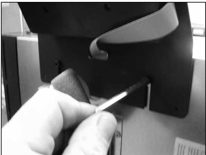
- Loosen the two screws mounted on the back of the appliance (see image 1) so that the two slots of the display mounting plate fit between the screws.
- Press the mounted rings, which are located around the two loosened screws, against the appliance's wall.
- Place the display plate with the display by sliding it with the slots between the head of the bolt and the ring (see image 2).
- Then tighten both screws so that the display plate is securely fastened (see image 3).
- Check that the flat cable can move freely behind the display plate.
- Remove the protective material around the flat cable (see image 4).
- Slide the flat cable into the protective gutter (see image 5).
3.2 POSITIONING THE ROOM TEMPERATURE SENSOR
The room temperature sensor is located at the rear of the appliance. Unroll the sensor cable so that the end of the sensor is 5 cm from the floor (see figure 6). Ensure that the sensor does not come into contact with the hot parts of the appliance.
4. MINIMUM REQUIREMENTS FOR THE FLUE / CHIMNEY
The chimney / flue is a very important part of the installation. This chapter discusses the minimum requirements that the flue/chimney of the pellet stove must meet to ensure proper functioning of the appliance.

Local/national rules, regulations, ordinances and standards must be observed at all times. If the installation instructions provided in this manual deviate from local/national and/or regional legislation, the latter conditions must be applied.
The manufacturer and distributor expressly disclaim all responsibility if:
• The installation does not comply with national/local legislation.
- If there is no national/local legislation, the minimum requirements for installation as described here are not followed.
4.1 MINIMUM REQUIREMENTS FOR THE CHIMNEY
- Only one appliance may be connected to the chimney. Connecting multiple appliances to the same chimney is not permitted. Never connect two stoves, an extractor hood and a stove, a second chimney, etc., etc., to a single chimney. See figure 7.
- Only use approved installation materials when installing the chimney. The chimney of this appliance must be heat-resistant (minimum 450°C). Consult local/national rules, regulations, ordinances and standards for the requirements of installation materials for chimneys.
- The chimney and the chimney outlet must be placed at a sufficient distance from combustible and flammable materials. Consult local/national rules, regulations, ordinances and standards for the installation requirements.
- The appliance must be connected to a chimney with a diameter equal to the specifications given in Table 1 of this installation manual. A chimney with a larger diameter is permitted, with a maximum diameter of 150 mm, provided that it complies with the specified chimney draught.
- Before installing a damper in the chimney flue, consult local/national rules, regulations, ordinances and standards to determine whether this is permitted.
- No electrical wiring may be installed through or near the chimney.
- The chimney must be smoke-tight.
- The chimney must be installed vertically so that there can be no blockages of the flue gases. If part of the chimney has to be installed horizontally, the length of the horizontal section may not exceed 2 metres and the horizontal section must have a rise, in the direction of the flue gases of at least 5°. See Table 1.
-
For an overview of the number of bends and T-pieces, the height of the chimney and the inner diameter of the pipes to be used for the flue, see Table 1.
-
It is recommended to install a T-piece with an inspection hatch at the bottom directly on the connection duct of the appliance. If a horizontal section is installed on the connection duct of the appliance, it is recommended to install a T-piece with an inspection hatch on the underside immediately after this horizontal section. Any moisture and solid particles will be collected in this T-piece and can be removed by opening the inspection hatch. The inspection hatch must be smoke- and watertight.
- The chimney outlet must be fitted with an approved chimney cap.
- The chimney and stove must be easily accessible for inspection and cleaning.
- The appliance must not be used to support the chimney/flue.
- If an existing flue/chimney is used, chimney, have it cleaned by a certified chimney cleaning company before installing the appliance. Soot and combustion residues can reduce the passage of an existing flue/chimney, preventing the appliance from functioning properly. Accumulations of soot and other contaminants can catch fire and cause dangerous situations. If an existing flue/chimney has a diameter of more than 150 mm, it must be modified and made suitable for a pellet stove by installing a pipe through the existing chimney.

Have an existing chimney inspected by a certified chimney company to determine whether it is suitable for burning solid fuel such as pellets.
- Have an existing chimney inspected by a certified chimney company to determine whether it is suitable for burning solid fuel such as pellets.
- Never place a flue gas fan in or on the flue/chimney. The appliance itself is equipped with a flue gas fan. Installing an additional flue gas fan in or on the flue may compromise the proper functioning of the appliance.
- A chimney or part of the chimney that is installed outside the house must be double-walled. See figure 8. Inside the house, a single-walled pipe may be used.
Figure 8:
A. Vertical section of the chimney
B. Air inlet
C. Lockable T-piece
D. Single-walled pipe
E. Double-walled pipe
F. Horizontal section of the chimney.
- For examples of appliance's installation, see figures 9A to 9E.
Figure 9A:
A. Draft hood
B. Wall bracket
C. Chimney pipe connection ring
D. Double-walled appliance pipe
E. Double-walled insulated wall duct
F. T-piece with sealing cap
G. Sealing cap
H. Combustion air intake pipe
I. Single-walled chimney pipe (may also be double-walled)
J. Double-walled chimney pipe (may also be single-walled)
Figure 9B:
A. Draft hood
B. Storm collar
C. Roof support plate
D. Floor support plate
E. Chimney pipe connection ring
F. Double-walled insulated chimney pipe
G. Floor support plate
H. Fire separation plate
I. Double-walled insulated chimney pipe (may also be single-walled up to the ceiling)
J. T-piece with cap
K. Combustion air intake pipe
Figure 9C:
A. Draft hood
B. Storm collar
C. Roof support plate
D. Floor support plate
E. Chimney pipe connection ring
F. Concentric chimney pipe
G. Floor support plate
H. Fire separation plate
I. Concentric chimney pipe
J. Concentric T-piece with cap
K. Combustion air intake pipe, the combustion air is drawn in via the concentric pipe.
Image 9D:
A. Draft hood
B. Reduction plate for existing chimney
C. Chimney pipe to reduce the diameter of the existing chimney
D. Connection piece
E. Fire separation plate
F. Chimney pipe connection ring
G. Double-walled insulated chimney pipe (may be single-walled up to the connection of the chimney)
H. T-piece with cap
I. Combustion air intake pipe
Image 9E:
| A. | Double-walled insulated wall duct |
| B. | Horizontal chimney cap |
| C. | Rosette |
| D. | T-piece with sealing cap |
| E. | Combustion air intake pipe |
| F. | Single-walled chimney pipe (may also be double-walled) |
| Minimum requirements for chimney dimensions | Internal diameter of the flue 80 mm | Internal diameter of the flue 100 mm |
| Minimum vertical chimney length | 2.5 m | 2.5 m |
| Maximum vertical chimney length | 7.0 m | 10 m |
| Maximum vertical chimney length in the case of one T-piece or one bend | 7.0 m | 10 m |
| Maximum vertical chimney length in the case of two right-angle bends (90°) and one T-piece | 5.0 m | 8.0 m |
| Maximum number of right-angle bends (90°) | 3 | 4 |
| Maximum horizontal length | 2.0 m | 2.0 m |
| Minimum rise of horizontal flue gas section | 5° | 5° |
Table 1: Overview of the dimensions of the chimney/flue.

If more than one bend/T-piece is installed in the chimney, the maximum vertical height must be reduced by one metre for each additional bend/T-piece installed.
Example:
A chimney with an internal diameter of 80 mm has a T-piece and two 90° bends. This means that the chimney may be a maximum of 5 metres high, as the table shows that the chimney flue with a T-piece may be a maximum of 7 metres high. Two additional bends are installed, which means that the chimney must be 2 metres lower, i.e. 7 metres – 2 metres = 5 metres.
5. CONNECTION POINT OF THE CHIMNEY TO THE APPLIANCE
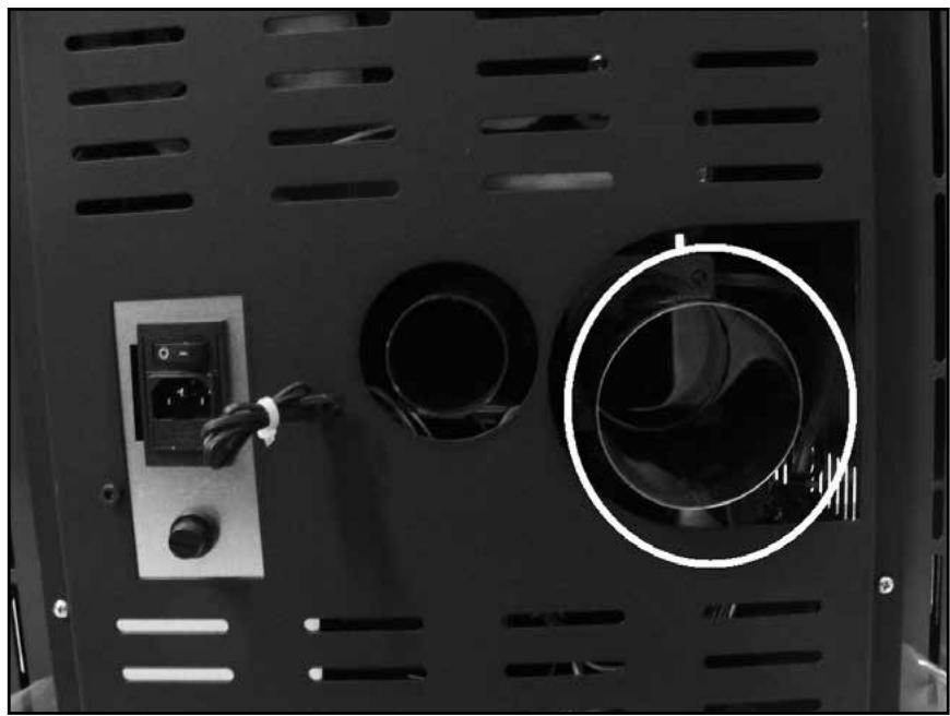
The chimney must be connected to the 80 mm pipe located at the rear of the appliance (see the circled pipe in figure 10). Ensure that the pipe is connected in such a way that no smoke can escape. For requirements regarding the chimney and the materials to be used, see chapter 4.
6. CONNECTING THE COMBUSTION AIR PIPE

- Ensure that the location of the fresh air inlet always complies with local regulations!
- Ensure that the fresh air inlet for combustion is covered with (for example) a grille to prevent animals from entering.
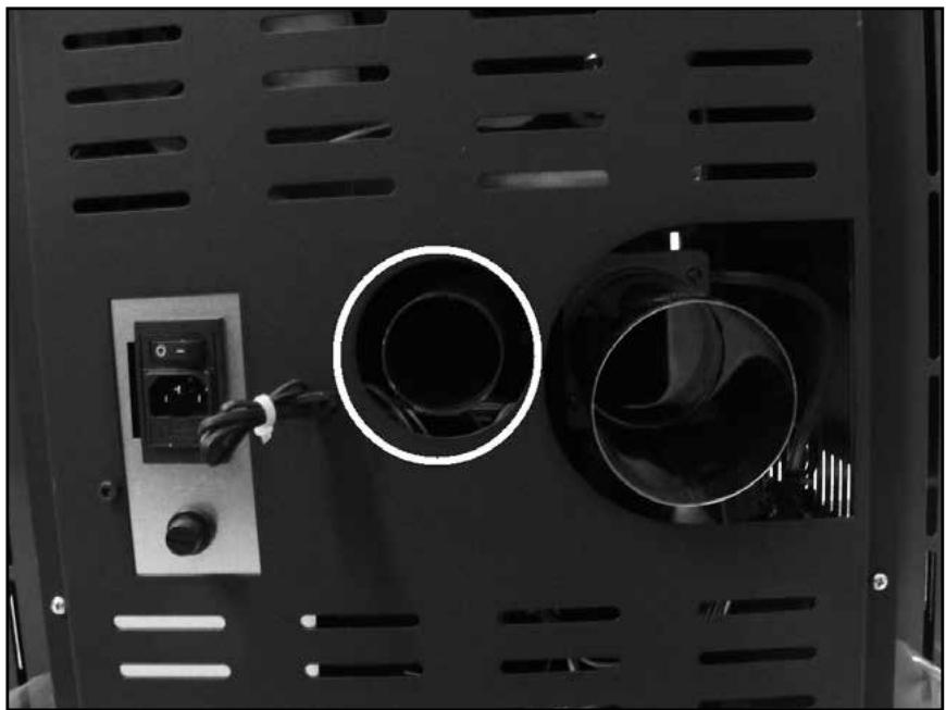
Connect a hose, or equivalent pipe, measuring 50 mm to the combustion air inlet located at the rear of the appliance, see figure 11. The other end of this hose, or equivalent pipe, must draw in clean air from outside. See figures 8 and 9A to


Ensure that the combustion air pipe can draw in fresh air from outside at all times.
7.
ENSURE THAT THE COMBUSTION AIR PIPE CAN DRAW IN FRESH AIR FROM OUTSIDE AT ALL TIMES.

The appliance must not be used if an air extraction system, hot air heating or other appliances that affect the air pressure in the room. This equipment must be switched off.
Ensure that sufficient fresh air enters the room. In addition to the normal ventilation requirements for the room, an additional 50 m^3 of air per hour is required.
Ventilation openings must be located close to the floor. Choose the locations of the openings carefully. Ventilation openings must not be blocked (either inside or outside).
Ensure that there is a fresh air inlet in the room with a cross-section of at least a quarter of the cross-section of the smoke outlet, with a minimum of 100 cm^2 .
The following guidelines apply to appliances installed in rooms with mechanical ventilation guidelines:
| Mechanical ventilation capacity [m3/h] | Additional ventilation cross-section required [cm2] |
| <50 | 140 |
| 50 – 100 | 280 |
| 101 – 150 | 420 |
8. PLACING THE APPLIANCE

Never install or perform maintenance on the appliance while the plug is connected to the mains. Always ensure that the appliance is disconnected from the mains!
- Never install or perform maintenance on the appliance while the plug is connected to the mains. Always ensure that the appliance is disconnected from the mains!
- Level the appliance by adjusting the adjustable feet. Use a spirit level for this. Ensure that all four adjustable feet are in contact with the floor with equal force.
- When installing the appliance, ensure that there is a clear distance between the appliance and walls or other obstacles as indicated in figure 12. If the walls or objects surrounding the appliance are made of combustible materials, ensure that they never exceed 60^ C when the burner is at its highest setting. If in doubt, apply a fireproof protective plate to the walls or move the objects.
- The appliance is designed for freestanding installation and is not suitable for built-in installation.
- Ensure that the grille where the heated air comes out can blow freely and is not blocked.
- Ensure that the return air intake grille is not blocked.
- If the floor consists of combustible material, this appliance must be placed on a fireproof base plate. This plate should be 40 cm larger at the front and 20 cm larger at the sides and back than the circumference of this appliance.
- Position the appliance so that it is easily accessible for maintenance work.
9. ELECTRICAL CONNECTION
An electrical power supply is required for this appliance. Please read the notes below carefully. The appliance must not be electrically connected until all other installation work has been completed. Before electrically connecting this appliance, also read chapters 3 and 3.1 of the user manual.
- Check that the mains voltage matches the connection voltage on the type plate.
- Use only a grounded outlet. If a grounded outlet is not available, one should be installed by a licensed installer.
- Never connect the appliance using an extension cord. If no suitable grounded outlet is available, one should be installed by a licensed installer.
-
Ensure that the power cable cannot touch hot parts of the appliance.
-
The power cable is supplied loose, one section must be attached to the appliance, see figure 13.
- Check that the power cord plug is appropriate for the outlet.
- Before inserting the plug into the outlet, check that the plug and power cord are not damaged.
- Make sure the power switch, which is located on the back of the appliance, is off.
- Ensure that the power plug is easily accessible so that it can be unplugged quickly and easily for maintenance or in an emergency.
- Do not pinch cable.
- Do not bend or kink cable.

A damaged power cord or plug should only be replaced by the supplier, by an authorized person or by an authorized service point.
9.1 ELECTRICAL DIAGRAM
Figure 14:
- Ambient temperature sensor
- Combustion gas line temperature sensor
- Differential pressure switch of combustion pipe
- Safety thermostat
- Worm drive pellets
- Display
- Display connection cable
- Ignition button
- Fan compartment
- Flue gas extraction fan
- Encoder cable
- Circuit board
10. FIRST USE
Before initial use, please read the operating instructions carefully (especially chapter 3).
- PRODUCT FICHE
| Supplier or brand name | Tectro | Tectro | |
| Model | TBH 570-3 | TBH 572-3 | |
| Appliance type | B | B | |
| Energy efficiency class | A+ | A+ | |
| Type of stove | Houtpellets | Houtpellets | |
| Direct heat output (*) | kW | 7,8 | 7,8 |
| Indirect heat output | 0,0 | 0,0 | |
| Energy efficiency index | 126 | 126 | |
| Power consumption (ignition / normal operation) | W | 300 / 100 | 300 / 100 |
| Connection voltage | V/Hz | 230/~50 | 230/~50 |
| Useful efficiency at rated capacity / reduced capacity (*) | % | 90,2 / 91,3 | 90,2 / 91,3 |
| Other precautions related to assembly, installation or maintenance of local space heating. | Raadpleeg handleiding | Raadpleeg handleiding | |
| CO content at 13% O2 nominal / reduced capacity (*) | % | 0,005 / 0,15 | 0,005 / 0,15 |
| Emissions in space heating at nominal heat output (13% O2) | mg/Nm3 | 12 | 12 |
| For rooms up to** | m3 | 170 | 170 |
| Flue gas outlet diameter | mm | 80 | 80 |
| Flue gas temperature at nominal capacity / reduced capa-city | °C | 135 / 84,4 | 135 / 84,4 |
| Chimney draft required | Pa | 10 | 10 |
| Chimney damper required | Mogelijk*** | Mogelijk*** | |
| Can be applied to chimney combination with flue | Nee | Nee | |
| Type of fuel (****) | Ø 6 mm Din+/Önorm+/EN+ | Ø 6 mm Din+/Önorm+/EN+ | |
| Nominal length / diameter of fuel | mm | 30 / 06 | 30 / 06 |
| Pellet hopper capacity | kg | 13 | 13 |
| Autonomy (min- max) | h | 7 - 18 | 7 - 18 |
| Main air vent | Ja | Ja | |
| Recirculation fan | Ja | Ja | |
| Air filter | Nee | Nee | |
| Net weight | kg | 77 | 77 |
(*) According to EN16510
(**) indicative only, varies by country/region
(***) To be determined by an authorized professional installer
(****) Use only recommended fuel
| ITEM | DESCRIZIONE | UM | Q.TA' | COD. |
| 1 | SERBATOIO PELLET | NR | 1 | 419700 |
| GRIGLIA SERBATOIO | NR | 1 | 410149 | |
| 2 | CARTER ARIA AMBIENTE | NR | 1 | 43020700 |
| 3 | MOTORIDUTTORE COCLEA 230/50/2RPM A | NR | 1 | 410006 |
| 4 | COCLEA | NR | 1 | 410015 |
| 5 | CONSOLE DISPLAY | NR | 1 | 411301 |
| 6 | CORPO STUFA | NR | 1 | 419800 |
| 7 | TOP SUPERIORE | NR | 1 | 43112100 |
| 8 | STAFFA SERBATOIO SX | NR | 1 | 419004 |
| 10 | TUBO INOX ESPULSIONE FUMI | NR | 1 | 420112 |
| 11 | VENTILATORE ESPULSIONE FUMI | NR | 1 | 410694 |
| 12 | GUARNIZIONE SILICONE ZOCCOLO-CHIOCCIOLA | NR | 1 | 419900 |
| 13 | PARATIA INTERNA CENTRALE | NR | 1 | 419405 |
| 14 | BATTIFIAMMA SUPERIORE | NR | 1 | 419407 |
| 15 | PARATIA INTERNA DX/SX | NR | 2 | 419406 |
| 16 | PIASTRA BATTIFUOCO ALLUMINATA SX | NR | 1 | 419404 |
| 17 | GRIGLIA MANDATA ARIA AMBIENTE | NR | 1 | 43112000 |
| 18 | STRUTTURA PORTA | NR | 1 | 43102900 |
| VETRO CERAMICO 205X285MM SP4MM | NR | 1 | 410016 | |
| 19 | MANIGLIA RETTANGOLARE | NR | 1 | 43102908 |
| 20 | PANNELLO FRONTALE SOTTO-PORTA | NR | 1 | 43106100 |
| 21 | PIASTRA BATTIFUOCO ALLUMINATA DX | NR | 1 | 419403 |
| 22 | FONDO INTERNO SX | NR | 1 | 43020601 |
| 23 | CASSETTO PORTA CENERE | NR | 1 | 419001 |
| 24 | BRACIERE IN GHISA | NR | 1 | 411685 |
| 25 | FONDO INTERNO DX | NR | 1 | 43020602 |
| 26 | PIEDINO ANTIVIBRANTE | NR | 4 | 410023 |
| 27 | ZOCCOLO | NR | 1 | 43020400 |
| 28 | ASSIEME CARICO PELLET | NR | 1 | 43020200 |
| 29 | SUPPORTO COCLEA | NR | 1 | 43020800 |
| 30 | STAFFA SERBATOIO DX | NR | 1 | 419003 |
| 31 | SCHEDA ELETTRONICA | NR | 1 | 410615 |
| 32 | FIANCO METALLO NERO / BORDEAUX | NR | 2 | 43111700K/B |
| 33 | TERMOSTATO SICUREZZA | NR | 1 | 410009 |
| 34 | MODULO ALIMENTAZIONE POLYSNAP | NR | 1 | 410011 |
| 35 | TUBO PORTA RESISTENZA | NR | 1 | 419300 |
| 36 | PRESSOSTATO FUMI | NR | 1 | 410007 |
| 37 | STAFFA SUPPORTO SCHEDA ELETTRONICA | NR | 1 | 419006 |
| 38 | RESISTENZA ACCENSIONE | NR | 1 | 410010H |
| 39 | VENTILATORE TANGENZIALE | NR | 1 | 410004T |
| 40 | SCHIENA | NR | 1 | 419005 |
| ∅ | CAVO FLAT (SCHEDA-DISPLAY) | NR | 1 | 410238 |
| ∅ | CABLAGGIO COMPLETO | NR | 1 | 411380 |
| ∅ | SONDA TEMPERATURA FUMI | NR | 1 | 411307 |
| ∅ | SONDA TEMPERATURA AMBIENTE | NR | 1 | 410240 |
| ∅ | TRECCIA GUARNIZIONE PORTA D14MM | ML | 1,4 | 410020 |
| ∅ | NASTRO GUARNIZIONE VETRO | ML | 1 | 410029 |
| ∅ | LIBRETTO ISTRUZIONI | NR | 1 | ??? |
| ∅ | MANUALE INSTALLAZIONE | NR | 1 | ??? |
2.

natural_image
Close-up of a mechanical component with a black arrow pointing to a small cylindrical part, no visible text or symbols.3.
natural_image
Close-up of a hand using a screwdriver to adjust or install a mechanical component (no visible text or symbols)4.

6.

7.

natural_image
Diagram of a vertical structure with two internal compartments and a central shaft, labeled 'NO' (no text or symbols on the diagram itself)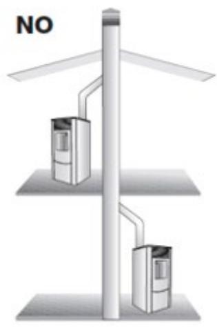
natural_image
Diagram of two vertical structures with internal compartments and piping, labeled 'NO' (no text or symbols on structures)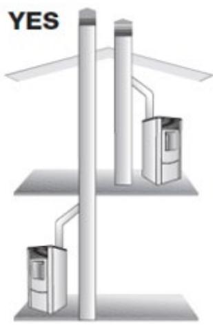
8.


9B.

9C.


9E.

L'ÉVACUATION DES GAZ DE COMBUSTION DOIT ÊTRE CONFORME AUX LOIS ET RÉGLEMENTATIONS LOCALES. VEUILLEZ VÉRIFIER AUPRÈS DE VOTRE INSTALLATEUR QUALIFIÉ ET LE FAIRE INSTALLER.


ROOKGAS AFVOER MOET VOLDOEN AAN PLAATSELIJKE WET- EN REGELGEVING. GELIEVE DIT BIJ EN MET UW LOKALE GEKWALIFICEERDE INSTALLATEUR TE CONTROLLEREN EN LATEN INSTALLEREN.
10.
natural_image
Interior view of a black industrial machine with ventilation slots and a circular vent (no text or symbols visible)11.
natural_image
Interior view of a black industrial enclosure with ventilation grilles and a circular opening (no text or symbols visible)12.

13.

natural_image
Close-up of a hand inserting a cable into an electrical outlet plug (no visible text or symbols)14.


Distributed in Europe by PVG Holding B.V.
D Benötigen Sie weitere Informationen oder treten Probleme auf, besuchen Sie bitte unsere Website www.pvg.eu, oder setzen Sie sich mit unserem Kundendienst in Verbindung (T: +31 412 694 694).
For alle yderligere oplysninger eller ved eventuelle problemer med apparatet henvises til www.pvg.eu eller det lokale Kundecenter (T: +45 77 34 33 30).
Es Si necesita información o si tiene algún problema, visite nuestra página Web www.pvg.eu, o póngase en contacto con el servicio cliente (T: +34 916 113 113).
F Si vous souhaitez obtenir des informations supplémentaires ou si vous rencontrez un problème, rendez-vous sur notre site Web (www.pvg.eu) ou contactez notre service client (T : +33 2 32 96 07 47 / +32 (0)3 326 39 39).
FIN Jos haluat huoltoapua, lisätietoja tai laitteen kanssa tulee ongelmia, tutustu verkkosivustoon osoitteessa www.pvg.eu tai kysy neuvoa PVG kuluttajapalvelukeskuksesta (T: +45 77 34 33 30).
GB If you need information or if you have a problem, please visit the our website (www.pvg.eu) or contact our sales support (T: +31 412 694 694).
① Per informazioni e in caso di problemi, visitate il sito Web www.pvg.eu oppure contattate il Centro Assistenza Clienti (T: +39 0571 628 500).
Hvis du trenger informasjon, eller hvis du har et problem med produktet, kan du gå til nettsidene www.pvg.eu. Alternativt kan du kontakte med PVG' forbrukertjeneste (T: +45 77 34 33 30).
NL Als u informatie nodig hebt of als u een probleem hebt, bezoek dan de onze website (www.pvg.eu) of neem contact op met de afdeling sales support (T: +31 412 694 694 / +32 (0)3 326 39 39).
P Se necessitar de informações ou se tiver problemas, visite o Web site www.pvg.eu ou contacte o Centro de Assistência (T: +34 916 113 113).
PL W przypadku problemów i w celu uzyskania szczegółowych informacji odwiedź stronę internetową PVG dostępną pod adresem www.pvg.eu lub skontaktuj się z Centrum kontaktów PVG (T: +48 48 613 00 70)
Om du behöver service eller information eller har problem med apparaten kan du besöka www.pvg.eu eller kontakta PVG kundtjänst (T: +45 77 34 33 30).
SLO Če želite dodatne informacije, obiščite spletno mesto podjetja na naslovu www.pvg.eu ali pokličite na telefonsko (T: +386 (0)41 674 139).

natural_image
Empty gray square with four corner brackets (no text or symbols)

- B JE NE DISPOSE PAS D'UNE ARRIVÉE D'AIR INDÉPENDANTE
- SAFETY INSTRUCTIONS:
- ASSEMBLY INSTRUCTIONS FOR SUPPLIED PARTS
- ASSEMBLY OF THE DISPLAY (IF NOT ALREADY INSTALLED)
- POSITIONING THE ROOM TEMPERATURE SENSOR
- MINIMUM REQUIREMENTS FOR THE FLUE / CHIMNEY
- MINIMUM REQUIREMENTS FOR THE CHIMNEY
- Figure 8:
- Figure 9A:
- Figure 9B:
- Figure 9C:
- Image 9D:
- Example:
- CONNECTION POINT OF THE CHIMNEY TO THE APPLIANCE
- CONNECTING THE COMBUSTION AIR PIPE
- 7.
- ENSURE THAT THE COMBUSTION AIR PIPE CAN DRAW IN FRESH AIR FROM OUTSIDE AT ALL TIMES.
- PLACING THE APPLIANCE
- ELECTRICAL CONNECTION
- ELECTRICAL DIAGRAM
- Figure 14:
- FIRST USE
- 8.
- 9E.
- 13.
- 14.
- Distributed in Europe by PVG Holding B.V.
Brand : TECTRO
Model : TBH-570-3
Category : Pellet stove