HC600 - Garage door opener CHAMBERLAIN - Free user manual and instructions
Find the device manual for free HC600 CHAMBERLAIN in PDF.

User questions about HC600 CHAMBERLAIN
0 question about this device. Answer the ones you know or ask your own.
Ask a new question about this device
Download the instructions for your Garage door opener in PDF format for free! Find your manual HC600 - CHAMBERLAIN and take your electronic device back in hand. On this page are published all the documents necessary for the use of your device. HC600 by CHAMBERLAIN.
USER MANUAL HC600 CHAMBERLAIN
AT/BA/BE/BG/CH/CY/CZ/DE/DK/ES/
FR/GB/GR/HR/HU/IE/IS/IT/LU/MT/NL/
NO/PL/PT/RO/RU/SE/SI/SK/TR/YU
Manager, Regulatory Affairs
Chamberlain GmbH
D-66793 Saarwellingen
October, 2005


Manager, Regulatory Affairs
Chamberlain GmbH
D-66793 Saarwellingen
October, 2005

BaIbIaP.KeckhoH

This safety alert symbol means "Caution" - failure to comply with such an instruction involves risk of personal injury or damage to property. Please read these warnings carefully.
This gate drive mechanism is designed and tested to offer appropriately safe service provided it is installed and operated in strict accordance with the following safety rules.
Incorrect installation and/or failure to comply with the following instructions may result in serious personal injury or property damage.

Do not wear rings, watches or loose clothing while servicing or installing a gate opener.
Installation and wiring must be in compliance with your local building and electrical installation codes. Power cables must only be connected to a properly earthed supply.
Entrapment between the moving gate and walls due to the opening movement must be avoided by using safety edges or IR sensors when necessary.
Please remove any locks fitted to the gate in order to prevent damage to the gate. A special E-Lock is available as accessory.

After installation, ensure that the gate opener system is properly adjusted and that the safety system and the manual release function correctly.
This drive must not be used with a gate incorporating a wicket door.
The actuating member of a biased-off switch, if installed, is to be located within direct sight of the gate but away from moving parts. Unless it is key operated, it is to be installed at a minimum height of 1,5m and not accessible to the public.

It is important to make sure that the gate always runs smoothly. Gates which stick or jam must be repaired immediately. Employ a qualified technician to repair the gate, never attempt to repair it yourself.

Keep additional accessories away from children. Do not allow children to play with any controls. Keep remote controls away from children. Operate gate when it is in full view and no one is near the gate. A gate can cause serious injuries or death as it opens or closes.

Disconnect electric power to the system before making repairs or removing covers. Install an all pole disconnect switch in the permanent wiring if one is not present.

Make sure that people who install, maintain or operate the gate drive follow these instructions. Keep these instructions in a safe place so that you can refer to them quickly when you need to.

The gate drive system is to be regularly examined for any signs of wear and tear or damage. The gate drive system must not be used if repair or adjustments are needed.
| Content | Page | Figures |
| Safety rules | 1 | |
| Content of the carton | 1 | 1 |
| Before you begin | 1 | 1-5 |
| Preparations | 2 | 1-11 |
| Installation | 1-2 | 1-12 |
| Technical Data | 3 | |
| Typical configuration | 3 | |
| Replacement Parts | 13 |
CONTENT OF THE CARTON
- Motor 2x
- Base Plate 2x
- Release key 2x
- Hardwarebag 2x
- Manual 1x
Arm straight 2x
Arm bent 2x - Electronic control 1x with box and radio receiver
- Flashing Lamp 1x
Infrared Sensor 1x
Transmitter 2x
INSTALLATION
BEFORE YOU BEGIN
The HC600 is suitable for use with wide pillars up to 30cm. The max. width of the swing gate should not exceed 3,0m / 250kg . The maximum recommended opening angle of the gate is 125 degrees. Ensure that ample space is available next to the drive for the arms and assembly. Gates exposed to a high wind load must be fixed with an electric lock for additional protection. Stops should also be mounted on the ground to prevent gate rattle or flutter. There are many factors to consider when choosing the right drive mechanism. Assuming that a gate functions properly, "startup" is the most difficult phase, once the gate is in motion, significantly less force is usually required to move it.
- Gate size: The gate size for this drive must not be more than 3.0m . Wind can brake or distort the gate, thereby increasing the amount of force needed to move it considerably.
- Gate weight: The weight of the gate must not be more than 250kg .
- Effect of temperature: Be sure that the ambient temperature where the drive is installed will be between -20 to +55 deg since low outdoor temperature can prevent the motor from starting. High outdoor temperatures along with frequent use can cause the motor thermal protection to operate. Wait 15 minutes if this has occurred.
- Frequency of operation/operating time: This gate opener is designed for intermittent duty and will cause the motor thermal protection to operate if it is operated continuously. It is designed to operate for over 5 cycles continuously or less than 30% duty cycle. Wait 15 minutes if this has occurred.
INSTALLATION CHECKLIST - PREPARATIONS
Check the carton contents (figure 1) and read the instructions carefully. Make sure your gate equipment operates perfectly. The gate must run evenly and smoothly and must not stick at any point. Remember that the ground level may be several centimeters higher in winter. The gate must be stable and as free of backlash as possible in order to prevent any unwanted to and fro movement. The more smoothly the gate leaf runs, the more sensitive the force adjustment must be.
Note down any materials you still need and obtain them before starting to install. Heavy-duty plugs, bolts, gate stops, cables, distribution boxes, tools, etc.
GATE TYPES
The gate type (figure 2) determines the location where the drive mechanism is installed. If the gate stop is on the ground, the drive mechanism must also be installed at a height that is as low as possible so that it cannot twist the gate. Use only parts of the gate frame for fixing purposes.
For steel gates, the gate fitting must be attached to the main frame. If you are uncertain whether the available support is sufficiently stable, reinforce it.
In the case of wooden gates, the gate fitting must be through bolted. It is advisable to fit a plate from the outside so that the fixing brackets cannot become loose over time. Thin wooden gates must also be reinforced in order to withstand the stresses encountered.
GATE SITUATION
The gate drive mechanism is suitable for use in conjunction with pillars with a max. thickness of 30cm. The amount of room around the pier affects the opening angle and the position of the arms (figure 4).
A different opening angle can be set for the left-hand wing as compared with the right-hand one (figure 3).
GATE STOPS
A SWING GATE NEEDS A FIXED GATE STOP IN BOTH THE OPEN AND CLOSE DIRECTIONS. Gate stops save wear and tear on the drive mechanism, gate and fittings. Operating a gate without fixed limit stops results in poor performance. It is often dangerous, leads to premature wear in the case of heavy gates often exposed to wind stress.
GATE FITTING
For steel gates, fixings should be welded on or through bolted. When through bolting the gate, use large washers or a plate on the other side. The drive mechanism exerts an extremely high force on this joint.
Fixings must be through bolted for wooden gates. Wood deflects under load and the bolt will become loose. Due to movement caused by repeated loading, the wood deflects more and more until the gate no longer closes correctly and has to be repaired.
The arm should not be mounted while fully extended (see Fig. 4). The drive is self-locking. The unit should be mounted with an offset of about 90 degrees. If the arm's point of contact is further to the outside, it will require less room at the side but it will be harder to drive. Mount the drive provisionally (e.g. with finger-tight thumb-screws), and check the mounting position by opening the gate manually.
OPENING DRIVE
A type 1 Phillips screwdriver (small) is required if the drive hood needs to be dismantled. The drive hood can be taken off once the screws have been removed. Now the drive can be unscrewed from the base plate (4x lock screws) (figure 6-8).
Take care when unlatching the drive for manual operation. The door leaf can move in an uncontrolled way, especially if it is defective and not properly balanced.
The release key should be inserted into the side openings and turned approx. 180 degrees until it cannot turn any further. The drive has now been released. To re-engage it, the key should be turned back to its original position (figure 11).
INSTALLATION OF THE UNIT
- Mount the arms on the motor (Fig. 5). Switch to manual operation by inserting and turning the hexagonal key provided (Fig. 11).
- Select and mark the mounting height on the pier (Fig. 4+5).
- The side of the gate mounted to the pier should be stable. If necessary, it should be reinforced, e.g. with a metal frame. Make sure that the screws used are long enough to ensure stable mounting. Ensure that there is enough room (Fig. 4+9).
- Finding the right mounting position. Mount the drive on the pier and attach it to the gate. The drive exerts a great amount of force on the pier. A steel pier will provide the most stability. Welding the supplied hinge plate directly on to the pier will generally provide enough room for mount. In the case of thick brick or concrete pillars, the hinge plate should be welded onto a support plate, that is mounted in such a way that the plugs cannot work loose. Adhesive shear connectors are better than steel or plastic wedge anchors for this purpose. A threaded rod is then mounted into the masonry with a stress free adhesive seal. A watertight distribution unit should be mounted on the pier next to the hinge plate. The feed cable for the wing gate opener is led into this unit from underneath.
Several openings for the cable have been pre-punched in the base and need only be broken through, as required. The drive must be standing on a solid surface for the purposes of breaking the holes through to prevent the PVC base plate from breaking. A small, flat screwdriver should be used for breaking the holes through. For this purpose, tap on the screwdriver handle with the palm of the hand from the inside. Repeat this as necessary at several points on the pre-marked circle. The pre-punched area can then be easily removed and the strain relief supplied as standard fitted in its place.
Once the pier plate has been mounted, the drive can then be fitted. The drives can be used left or right without requiring conversion. For the purposes of fitting the drive, the lock screws need to be re-inserted and tightened up.
SAFETY MEASURES
THE WING GATE OPENER SHOULD ALWAYS BE OPERATED IN CONJUNCTION WITH FLASHING LIGHTS AND PHOTOELECTRIC BARRIERS FOR ADDED SAFETY.
In any case, take care to comply with the relevant standards and regulations.
Should the force generated by the moving wing at its closing edge exceed 400N , additional safety features (fotocells, contactstrips) must be fitted. Any safety features fitted must comply with the appropriate standards.
FINAL REMARKS
Arrange the handover of the wing gate opener with your customer. Make sure that persons will operate the gate are familiar with its functions and can operate them without problems. Have your customer practice operating the gate until he is fully acquainted with all the following:
- Main switch.
- Rules of operation (e.g. do not drive through while the gate is still opening).
- Additional safety features (photoelectric barrier, flashing lights, etc.).
- Switch to manual operation in case of power failure.
- Provide the customer with a full set of instructions. Inform him to keep them in a safe place and read them when possible.
- Reference a checklist, so that you have a record of which functions have been explained and of any points not dealt with.
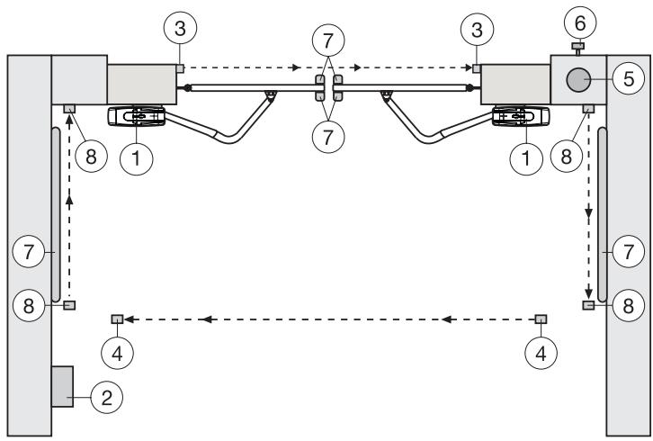
TYPICAL CONFIGURATION OF A UNIT
- Motor
- Control board
- photocell (active for closing), max. height 200 mm First photocell.
- photocell (active for opening), max. height 200 mm
Second photocell. - Flashing light (optional)
Important visual information on the movement of the gate. - Key-operated switch
Is mounted on the outside. The gate is opened by key or by entering a number. - Contact strip (optional)
Safeguards the gate on being touched. Contact strips can be mounted on the gate or on the pillars. If required, contact strips must be mounted at a height of up to 2.5m . - photocell (active for opening/closing), max. height 200 mm (optional)
TECHNICAL DATA
Model HC600
Mains supply 230V-240V/50
Power consumption 400W
Nominal power 250W
Force max. 250Nm
Nominal load 1.1A
Capacitor 8uF
Temperature -20o to +55o
Frequency Cycles/hr 30%
Weight 1 Motor approx. 9kg
Protection class IP44
Max. door width 3.0m
Max. door weight 250kg
ACCESSORIES
Model 84330EML 1-channel transmitter, 433.92MHz, with Rolling Code
Model 84333EML 3-channel transmitter, 433.92MHz, with Rolling Code
Model 84335EML 3-channel mini transmitter, 433.92MHz, with Rolling Code
Model 8747EML Keypad, 433.92MHz, with Rolling code
Model 760EML Key switch
Model 34EML 2-Function Keyswitch, flush mount
Model 41EML 2-Function Keyswitch, surface mount
Model 771EML Infrared barrier
Model ANT4X-EML Antenna
Declaration of Conformity
Automatic Gate Opener Models HC600 Series
are in conformity to the applicable
sections of StandardsEN300220-3 · EN55014 · EN61000-3 · EN60555, EN60335-1 · ETS
300683·EN60335-1:2002·EN60335-2-103:2003·EN55014-1:2000+A1+A2·
EN55014-2: 2001 • EN61000-3-2: 2000 • EN61000-3-3: 1995 + A1 • EN 301 489-3,
V1.3.1·EN 300 220-3 V1.1.1·EN13241-1
per the provisions & all amendments
of the EU Directives 73/23/EEC, 89/336EEC, 1999/5/EG
Declaration of Incorporation
Automatic Gate Opener, when installed and maintained according to all the
Manufacturer's instructions in combination with a Gate, which has also been installed and
maintained according to all the Manufacturer's instructions, meets the provisions of EU
Directive 89/392/EEC and all amendments.
I, the undersigned, hereby declare that the equipment
specified above and any accessory listed in the manual
conforms to the above Directives and Standards.
B.P.Kelkhoff
Manager, Regulatory Affairs
Chamberlain GmbH
D-66793 Saarwellingen
October, 2005


The control board complies with the latest EU
guidelines. One of these guidelines specifies that the closing forces at the gate edge must not exceed 400 N (40 kg) for the last 500 mm before the door is CLOSED. Above 500 mm, the maximum force at the gate edge must not exceed 1400 N (140 kg). If this cannot be ensured, a contact strip must be mounted on the gate at a height up to 2.5 m or on the pillar on the opposite side (EN12453).
BEGIN MET HET LEZEN VAN DEZE BELANGRIJKE VEILIGHEIDSINSTRUCTIES!

Manager, Regulatory Affairs
Chamberlain GmbH
D-66793 Saarwellingen
October, 2005


Manager, Regulatory Affairs
Chamberlain GmbH
D-66793 Saarwellingen
October, 2005