
ART300K - Garage door opener CHAMBERLAIN - Free user manual and instructions
Find the device manual for free ART300K CHAMBERLAIN in PDF.
User questions about ART300K CHAMBERLAIN
0 question about this device. Answer the ones you know or ask your own.
Ask a new question about this device
Download the instructions for your Garage door opener in PDF format for free! Find your manual ART300K - CHAMBERLAIN and take your electronic device back in hand. On this page are published all the documents necessary for the use of your device. ART300K by CHAMBERLAIN.
USER MANUAL ART300K CHAMBERLAIN
√73/23/EEC
1999/5/EC
Herstellererklarung
Manager, Regulatory Affairs
THE CHAMBERLAIN GROUP, INC.
September, 2003

Babaa P. Keckhoh
COMMENCEZ PAR LIRE CES IMPORTANTES CONSIGNES DE SECURITE

ARRET D'URGENCE (OPTION)
√89/336/EEC
73/23/EEC
1999/5/EC
Manager, Regulatory Affairs
THE CHAMBERLAIN GROUP, INC.
September, 2003

Dabbaa P. KeckhoH
PLEASE START BY READING THESE IMPORTANT SAFETY RULES • SAVE THESE INSTRUCTIONS

This safety alert symbol means "Caution" - failure to comply with such an instruction involves risk of personal injury or damage to property. Please read these warnings carefully.
This gate drive mechanism is designed and tested to offer appropriately safe service provided it is installed and operated in strict accordance with the following safety rules.
Incorrect installation and/or failure to comply with the following instructions may result in serious personal injury or property damage.

Do not wear rings, watches or loose clothing while servicing or installing a gate opener.
Installation and wiring must be in compliance with your local building and electrical installation codes. Power cables must only be connected to a properly earthed supply.
Entrapment between the moving gate and walls due to the opening movement must be avoided by using safety edges or IR sensors when necessary.
Please remove any locks fitted to the gate in order to prevent damage to the gate. A special E-Lock is available as accessory.
After installation, ensure that the gate opener system is properly adjusted and that the safety system and the manual release function correctly.
This drive must not be used with a gate incorporating a wicket door.
The actuating member of a biased-off switch, if installed, is to be located within direct sight of the gate but away from moving parts. Unless it is key operated, it is to be installed at a minimum height of 1,5m and not accessible to the public.

It is important to make sure that the gate always runs smoothly. Gates which stick or jam must be repaired immediately. Employ a qualified technician to repair the gate, never attempt to repair it yourself.

Keep additional accessories away from children. Do not allow children to play with any controls. Keep remote controls away from children. Operate gate when it is in full view and no one is near the gate. A gate can cause serious injuries or death as it opens or closes.

Disconnect electric power to the system before making repairs or removing covers. Install an all pole disconnect switch in the permanent wiring if one is not present.

Make sure that people who install, maintain or operate the gate drive follow these instructions. Keep these instructions in a safe place so that you can refer to them quickly when you need to.

The gate drive system is to be regularly examined for any signs of wear and tear or damage. The gate drive system must not be used if repair or adjustments are needed.
| Content | Page | Figures |
| Safety rules | 1 | |
| Content of the carton | 1 | 1 |
| Before you begin | 1 | 1-5 |
| Preparations | 2 | 1-11 |
| Installation | 2-5 | 1-13 |
| Initial Installation | 5 | |
| Technical Data | 6 | |
| Replacement Parts | 22 |
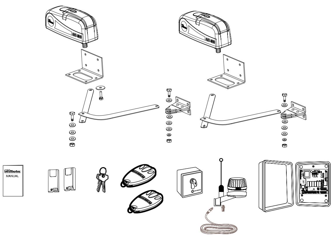
CONTENT OF THE CARTON
- Motor 2x
- Base Plate 2x
- Release key 2x
Hardwarebag 2x - Manual 1x
Arm straight 2x
Arm bent 2x - Electronic control 1x with box and radio receiver
- Flashing Lamp
Infrared Sensor 1x
Antenna 1x
Transmitter 2x
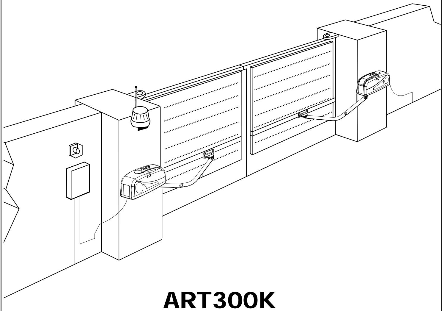
INSTALLATION
BEFORE YOU BEGIN
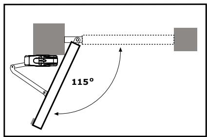
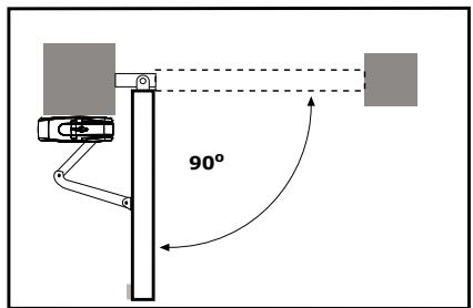
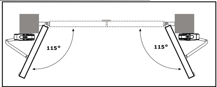
The ART is suitable for use with wide pillars, up to about 30cm in width. The maximum recommended opening angle of the gate is 125 degrees. Ensure that ample space is available next to the drive for the arms and assembly. Gates exposed to a high wind load must be fixed with an electric lock for additional protection. While the drive is fitted with internal limit switches, stops should also be mounted on the ground to prevent gate rattle or flutter. There are many factors to consider when choosing the right drive mechanism. Assuming that a gate functions properly, "startup" is the most difficult phase, once the gate is in motion, significantly less force is usually required to move it.
- Gate size: The gate size for this drive must not be more than 3.0m . Wind can brake or distort the gate, thereby increasing the amount of force needed to move it considerably.
- Gate weight: The weight of the gate must not be more than 250kg .
- Effect of temperature: Be sure that the ambient temperature where the drive is installed will be between -20 to +55 deg since low outdoor temperature can prevent the motor from starting. High outdoor temperatures along with frequent use can cause the motor thermal protection to operate. Wait 15 minutes if this has occurred.
- Frequency of operation/operating time: This gate opener is designed for intermittent duty and will cause the motor thermal protection to operate if it is operated continuously. It is designed to operate for over 5 cycles continuously or less than 30% duty cycle. Wait 15 minutes if this has occurred.
INSTALLATION CHECKLIST - PREPARATIONS
Check the carton contents (figure 1) and read the instructions carefully. Make sure your gate equipment operates perfectly. The gate must run evenly and smoothly and must not stick at any point. Remember that the ground level may be several centimeters higher in winter. The gate must be stable and as free of backlash as possible in order to prevent any unwanted to and fro movement. The more smoothly the gate leaf runs, the more sensitive the force adjustment must be.
Note down any materials you still need and obtain them before starting to install. Heavy-duty plugs, bolts, gate stops, cables, distribution boxes, tools, etc.
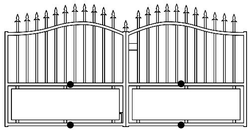
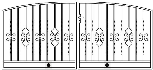
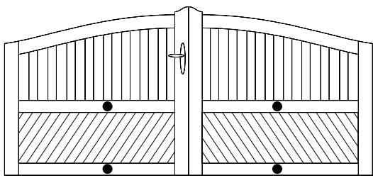
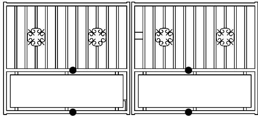
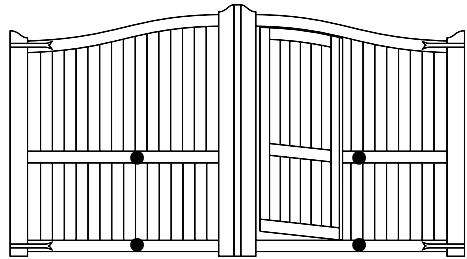
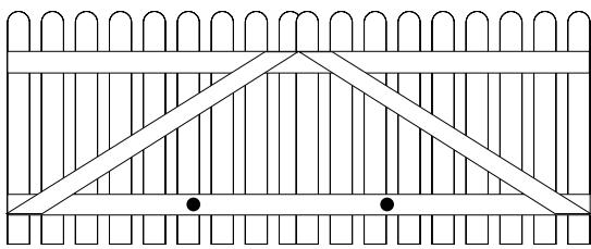
GATE TYPES
The gate type (figure 2) determines the location where the drive mechanism is installed. If the gate stop is on the ground, the drive mechanism must also be installed at a height that is as low as possible so that it cannot twist the gate. Use only parts of the gate frame for fixing purposes.
For steel gates, the gate fitting must be attached to the main frame. If you are uncertain whether the available support is sufficiently stable, reinforce it.
In the case of wooden gates, the gate fitting must be through bolted. It is advisable to fit a plate from the outside so that the fixing brackets cannot become loose over time. Thin wooden gates must also be reinforced in order to withstand the stresses encountered.
GATE SITUATION
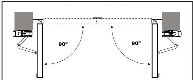
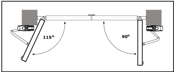
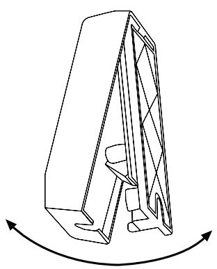
The gate drive mechanism is suitable for use in conjunction with pillars with a max. thickness of 30cm . The amount of room around the pier affects the opening angle and the position of the arms (figure 4).
The drive mechanism is equipped with built-in limit stops for both the OPEN and CLOSE directions. A different opening angle can be set for the left-hand wing as compared with the right-hand one.
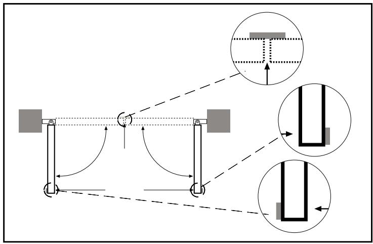
GATE STOPS
A SWING GATE NEEDS A FIXED GATE STOP IN BOTH THE OPEN AND CLOSE DIRECTIONS. Gate stops save wear and tear on the drive mechanism, gate and fittings. Operating a gate without fixed limit stops results in poor performance. It is often dangerous, leads to premature wear in the case of heavy gates often exposed to wind stress.
ELECTRICAL INSTALLATION
Installing the electronic control board:
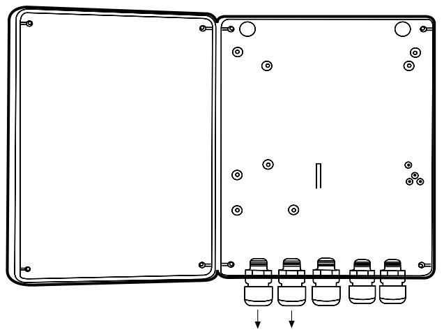
The motor control board is a microprocessor-controlled electronic appliance featuring state-of-the-art technology. It is equipped with all the connecting options and functions needed to guarantee safe operation. An overview of the wiring plan is shown in. The control box incorporating the motor control board should be installed with the cable intakes pointing downwards.
It should not be continuously exposed to direct sunlight.
The electronic equipment enables the pull and push forces to be set with great accuracy. If installed and set correctly, the gate/door can be stopped manually.
When in motion, the gate/door can be stopped at any time by operating the remote control, the push-button or the key-operated switch.
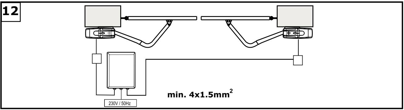
The cable leading from and to the control unit must be suitable for laying outdoors and, if required, run through ducts.
230 volt wiring and low-voltage lines may not be run via the same cable.
Generally speaking, the following minimum cable cross-sectional areas must be adhered to:
100-230Volt 1.5mm² or more
0-24Volt 0.5mm² or more
Tips: Bell wire is often problematic in practical use because it loses too much voltage if long lengths of wire are used.
Segregate the cables in cable trunking, i.e. motor cable and light barrier cable, especially in the case of key-operated switches and ON switches (from the house wiring system) to prevent interference where long lengths of cable are used.
OPENING DRIVE
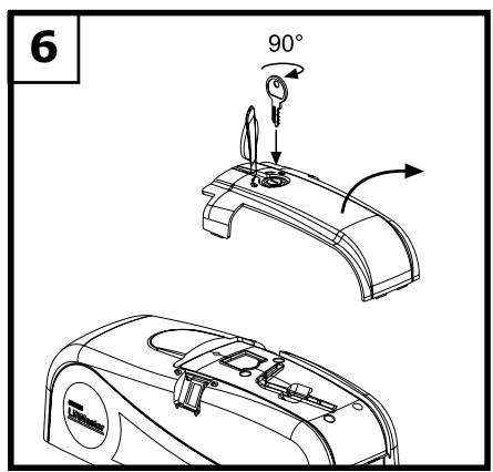
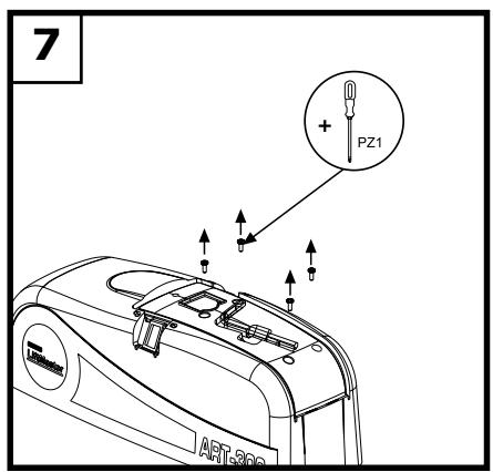
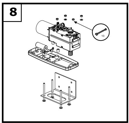
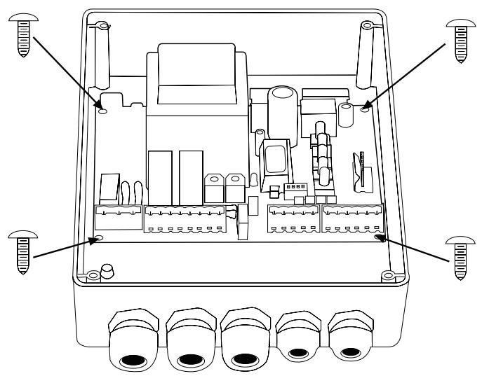
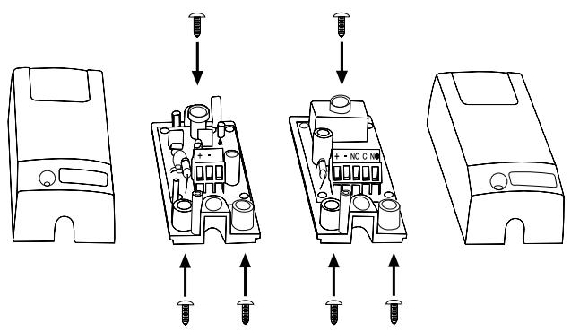
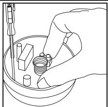
The release lock for the casing is located under the rubber waterproof cover. Use the socket spanner supplied in the hardware bag to lift the cover up. A type 1 Phillips screwdriver (small) is required if the drive hood needs to be dismantled. The drive hood can be taken off once the 4 screws have been removed. Now the drive can be unscrewed from the base plate (4x lock screws) (figure 6-8).
Take care when unlatching the drive for manual operation. The door leaf can move in an uncontrolled way, especially if it is defective and not properly balanced.
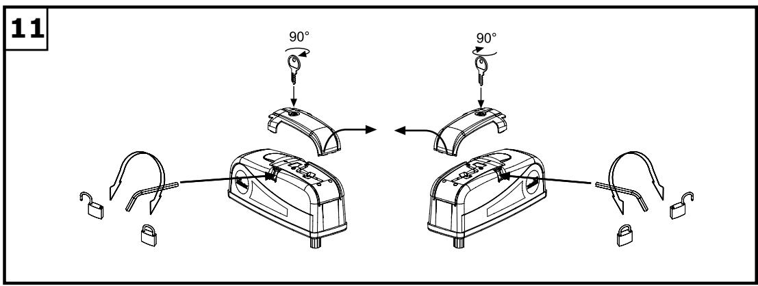
The release lock for the casing is located under the rubber waterproof cover. Use the socket spanner supplied in the hardware bag to lift the cover up. The release key located beneath the hood should be inserted into the side openings and turned approx. 180 degrees until it cannot turn any further. The drive has now been released. To re-engage it, the key should be turned back to its original position (figure 11).
NSTALLATION OF THE UNIT
- Mount the arms on the motor (Fig. 5). Switch to manual operation by inserting and turning the hexagonal key provided (Fig. 11).
- Select and mark the mounting height on the pier (Fig. 4+5).
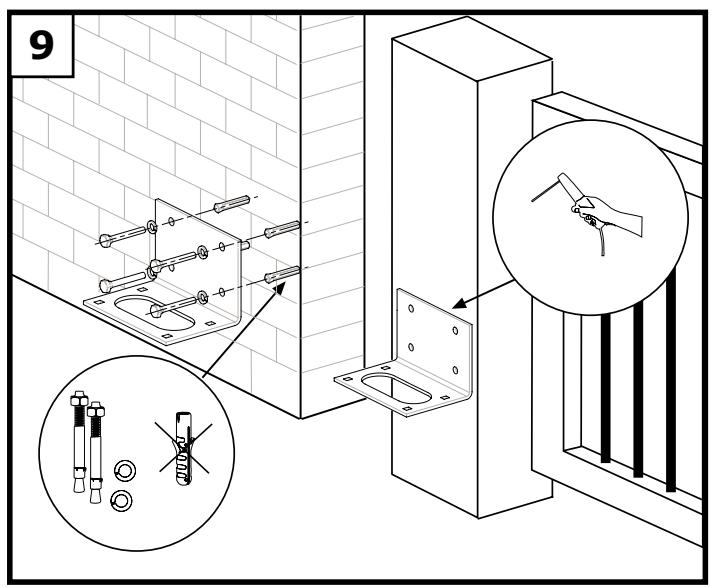
- The side of the gate mounted to the pier should be stable. If necessary, it should be reinforced, e.g. with a metal frame. Make sure that the screws used are long enough to ensure stable mounting. Ensure that there is enough room (Fig. 4+9).
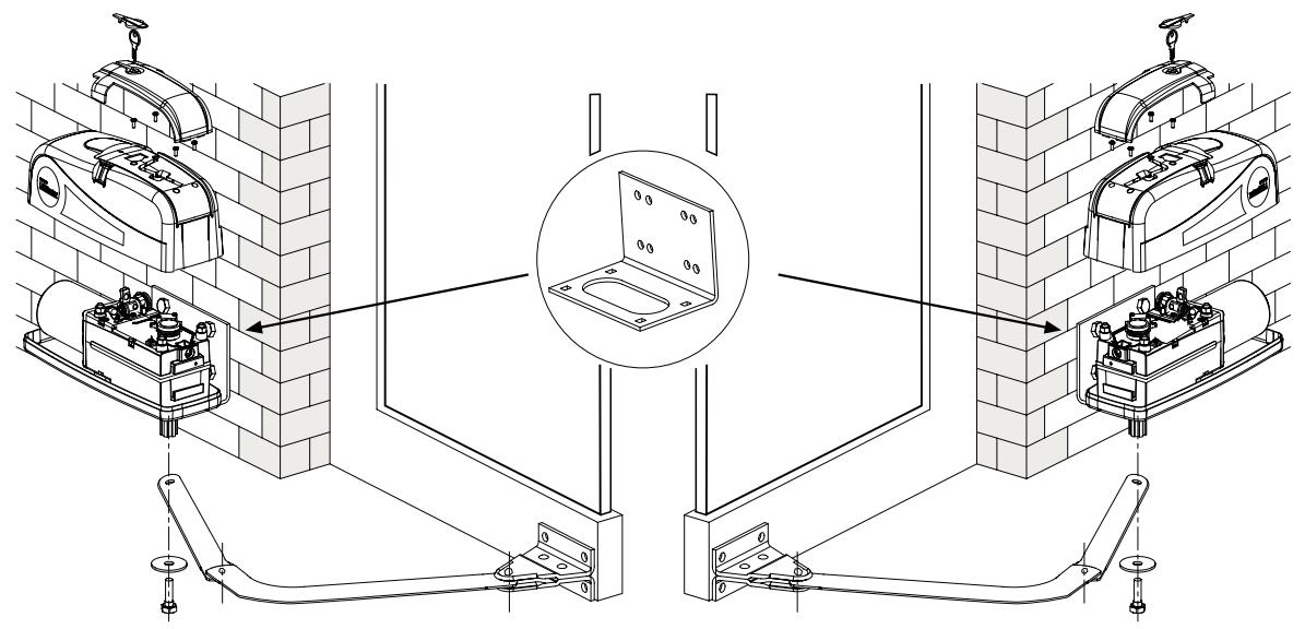
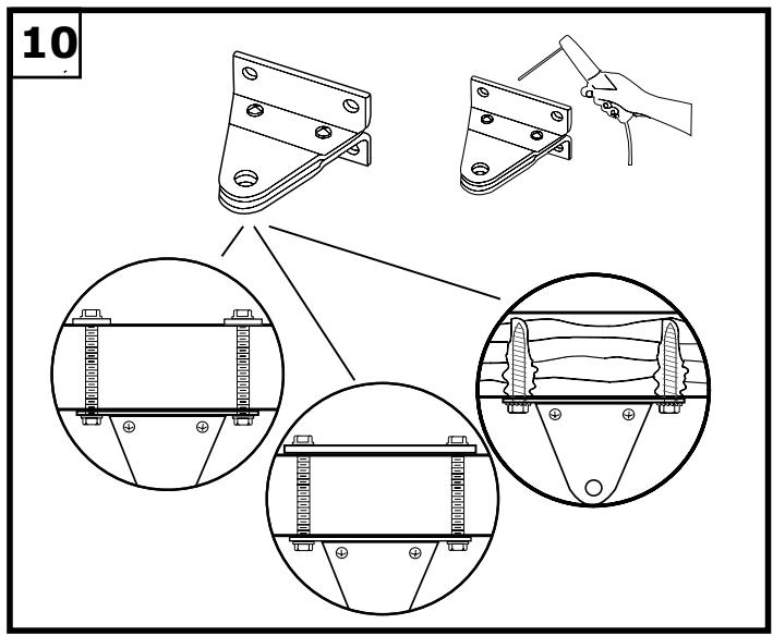
- Finding the right mounting position. Mount the drive on the pier and attach it to the gate. The drive exerts a great amount of force on the pier. A steel pier will provide the most stability. Welding the supplied hinge plate directly on to the pier will generally provide enough room for mount. In the case of thick brick or concrete pillars, the hinge plate should be welded onto a support plate, that is mounted in such a way that the plugs cannot work loose. Adhesive shear connectors are better than steel or plastic wedge anchors for this purpose. A threaded rod is then mounted into the masonry with a stress free adhesive seal. A watertight distribution unit should be mounted on the pier next to the hinge plate. The feed cable for the wing gate opener is led into this unit from underneath.
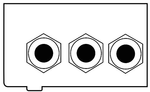
Several openings for the cable have been pre-punched in the base and need only be broken through, as required. The drive must be standing on a solid surface for the purposes of breaking the holes through to prevent the PVC base plate from breaking. A small, flat screwdriver should be used for breaking the holes through. For this purpose, tap on the screwdriver handle with the palm of the hand from the inside.
Repeat this as necessary at several points on the pre-marked circle. The pre-punched area can then be easily removed and the strain relief supplied as standard fitted in its place.
Once the pier plate has been mounted, the drive can then be fitted. The drives can be used left or right without requiring conversion. For the purposes of fitting the drive, the lock screws need to be re-inserted and tightened up.
GATE FITTING
For steel gates, fixings should be welded on or through bolted. When through bolting the gate, use large washers or a plate on the other side. The drive mechanism exerts an extremely high force on this joint.
Fixings must be through bolted for wooden gates. Wood deflects under load and the bolt will become loose. Due to movement caused by repeated loading, the wood deflects more and more until the gate no longer closes correctly and has to be repaired.
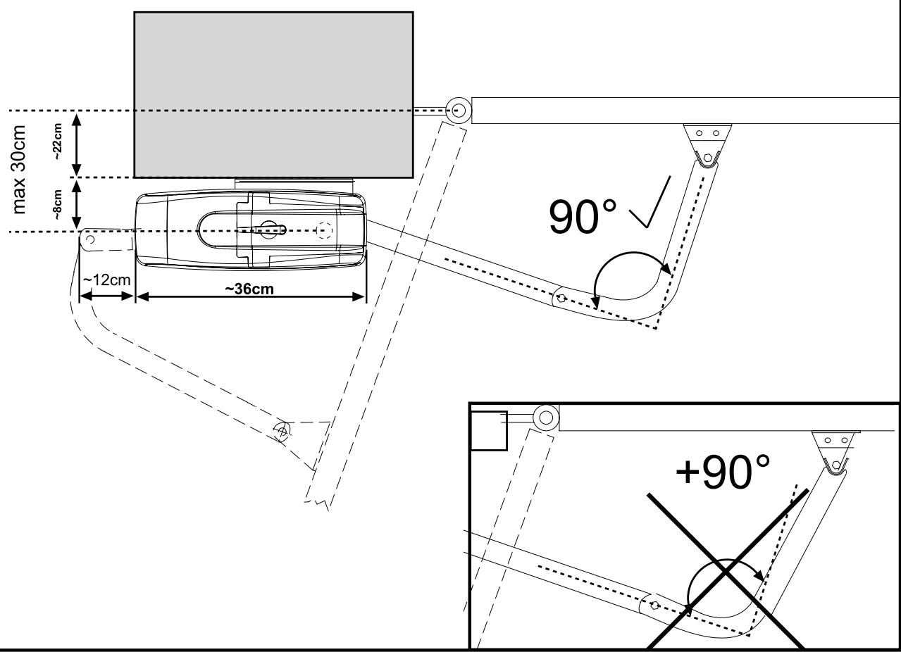
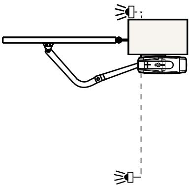
The arm should not be mounted while fully extended (see Fig. 4). The drive is self-locking. The unit should be mounted with an offset of about 90 degrees. If the arm's point of contact is further to the outside, it will require less room at the side but it will be harder to drive. Mount the drive provisionally (e.g. with finger-tight thumb-screws), and check the mounting position by opening the gate manually.
LIMIT SWITCH
The internal limit switch of the ART turns the drive off when the preset point is reached. Remove the cover of the drive unit, and turn the cam until the desired end point has been reached. Check which cam has which function (e.g. top cam opens gate).
Switch the drive on, let it run until the desired point is reached and interrupt the current with the aid of the main switch. Now turn the limit-switch dial to the microswitch trigger point.
Most control units have a time function. This should always be set 3 - 5 seconds more than the time actually required. The preliminary setting should be made for more than this to allow a safety margin. After the necessary adjustments to the system have been made, the time can be set more accurately. NB: The drive works more slowly under windy conditions.
SAFETY MEASURES
THE WING GATE OPENER SHOULD ALWAYS BE OPERATED IN CONJUNCTION WITH FLASHING LIGHTS, CONTACT STRIPS AND PHOTOELECTRIC BARRIERS FOR ADDED SAFETY.
In any case, take care to comply with the relevant standards and regulations.
Should the force generated by the moving wing at its closing edge exceed 400N , additional safety features (IR sensors, contact strips) must be fitted. Any safety features fitted must comply with the appropriate standards (Europe: EN60335-1).
ELECTRONIC CONTROL
The control board should be the last item to be connected, i.e. mounting the motors, laying the necessary cable and fitting light barriers or contact strips. If installation is to be performed in a permanent location, a means of disconnecting the equipment from the mains supply with a contact clearance of at least 3mm is needed (master switch).
Please note: in these instructions, relay contacts are designated NC (normal closed) or NO (normal open).
- NC contacts are closed and open
- NO contacts are open and close
Humidity and water will destroy the control board. Always make sure that water, humidity and condensation cannot enter the control box. It is vitally important that all openings and cable glands are sealed so that they are watertight.
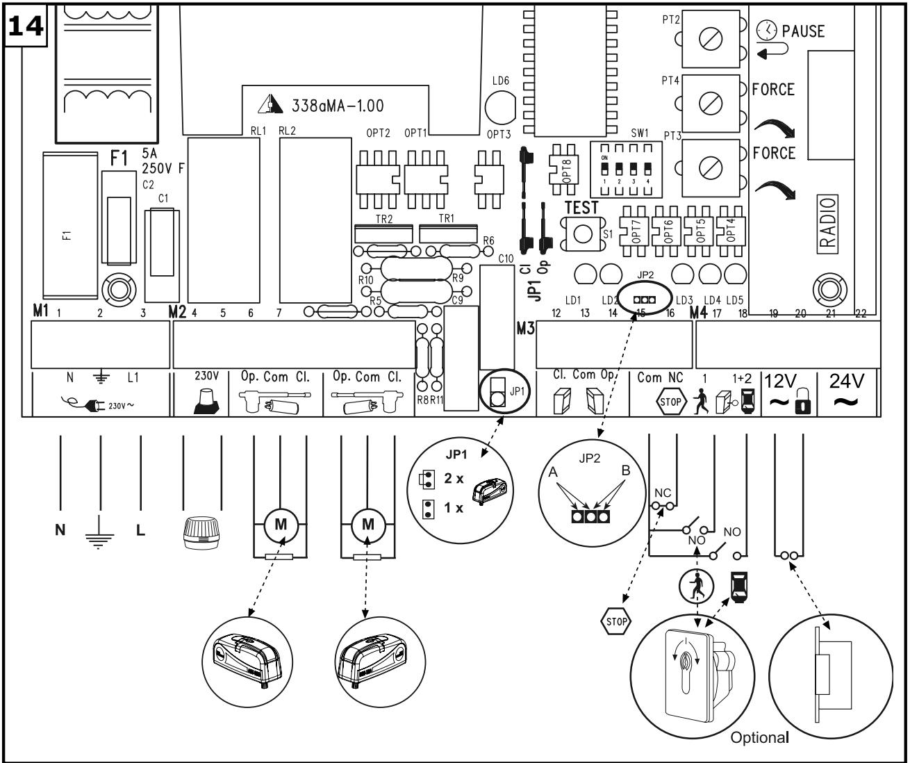
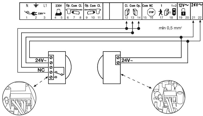
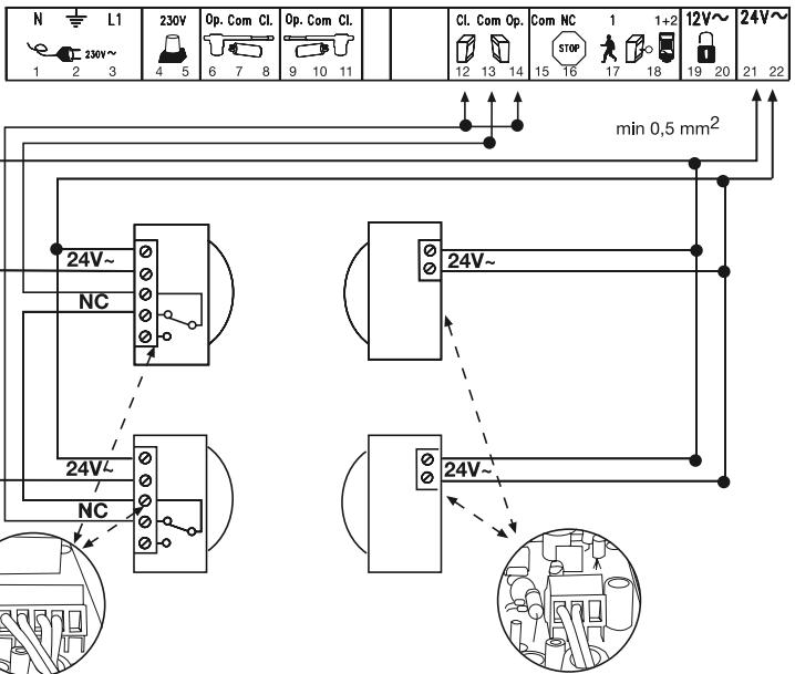
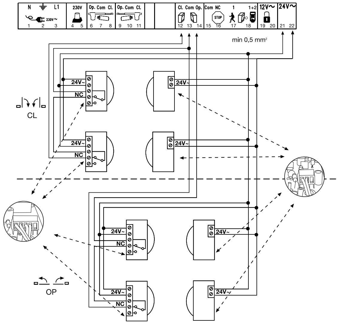
OVERVIEW OF CONNECTIONS 14
Description of terminal occupancy
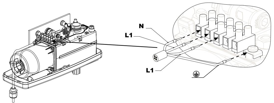
| Mains cable connection: | |
| Terminal 1 | N (blue) |
| Terminal 2 | PE (green/yellow) |
| Terminal 3 | L1 - 230 V (black) |
| Flashing lamp connection: | |
| Terminal 4 | L (230V) |
| Terminal 5 | L |
| Motor connections: | |
| First motor (M1): | |
| Terminal 6 | L1 direction of OPEN (brown/black) (+) capacitor) |
| Terminal 7 | N (blue) |
| Terminal 8 | L1 direction of CLOSED (black/brown) (+) capacitor) |
| Second motor (M2): | |
| Terminal 9 | L1 direction of OPEN (black/brown) (+) capacitor) |
| Terminal 10 | N (blue) |
| Terminal 11 | L1 direction of CLOSED (brown/black) (+) capacitor) |
| Infrared light barrier | |
| Terminal 12 | photocell (NC) active when closing |
| Terminal 13 | COM |
| Terminal 14 | photocell (NC) active when opening (without light barrier - jumper between 12, 13 and 14) |
| Emergency stop function | |
| Terminal 15 | COM |
| Terminal 16 | Stop (NC) with emergency stop switch jumper between 15 and 16 |
| External push-button | |
| Terminal 17 | External push-button (NO) motor 1 (pedestrian function) |
| Terminal 15 | COM |
| Terminal 18 | External push-button (NO) motors 1+2 (complete opening) |
| Electric lock connection | |
| Terminal 19 | Distribution voltage 12 V AC |
| Terminal 20 | Distribution voltage 12 V AC |
| Connection for additional equipment & light barrier: | |
| Terminal 21 | Distribution voltage 24 V AC (500 mA max.) Terminal |
| Terminal 22 | Distribution voltage 24 V AC |
DESCRIPTION OF JUMPER

JP1: MOTOR
OPEN: (without jumper): only for single-wing gates (only motor 1).
CLOSED: (with jumper): only for double-wing gates (motors 1 and 2).
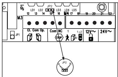
JP2: channel 2 radio receiver
If both learning channels are put together (A-side), the memory capacity of the radio receiver doubles in size. The gate can then only be fully opened. The "Pedestrian" function is no longer available.
A-side (optional): receiver channel 2 is connected up to receiver channel 1.
B-side (standard): the two radio receiver channels work separately from one another.
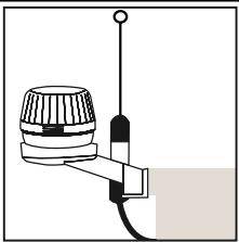
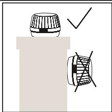
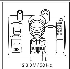
FLASHING LAMP 18 a
Usage of a flashing lamp is mandatory. It serves a safety-related purpose in that it warns persons in the vicinity of the gate/door that the given gate/door is moving. The flashing lamp is fixed using screws and wall plugs. Generally speaking, it is installed at the highest possible point (on a pillar).
Cross-sectional area: 0.75mm^2
3-pole voltage: 230 Volt/AC.
NFRARED SENSOR
The IR Sensor (fig. 16-19) provides additional safety to the gate/door and must be used. Its point of installation depends on the design of the given gate/door. Generally speaking, the light barrier is fitted at around knee height, approx. 35cm above ground level. IR Sensors comprise of a transmitter element and a receiver element, which must be located opposite one another. A screwdriver can be used to open the light barrier housing (plastic). The IR Sensor is fitted to the wall with small screws and wall plugs. Usage of a single set of IR Sensors is a minimum requirement; we recommend using two sets of IR Sensors (and other safety facilities if necessary).
It is possible to connect the IR Sensor as described below. Active when 'OPENING' (terminal 14) or active when 'CLOSING' (terminal 12). The instructions describe how to connect a single IR Sensor and therefore uses both fuse inputs, i.e. active in both directions. DIP switch 4 on the control unit controls the door wing's response if the light beam is interrupted while the gate/door is closing. An active IR Sensor (only) stops the gate/door or an active IR Sensor reverses the direction of the gate/door. The transmitter element needs a 2-pole cable, the receiver element a 4-pole one.
Cable cross-sectional area: 0.5mm^2 or more.
Voltage: 12/24Volt AC/DC. Terminals (12-13-14) (22/23).
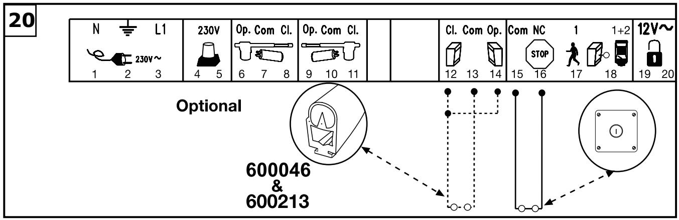
EMERGENCY STOP (OPTIONAL) 20
If a switch is connected, it can be used to stop or disable the installation. This immediately interrupts movement of the wing. Depending on the level of safety needed, the contact can also be connected on the gate/door to the IR Sensor's contacts. This immediately stops any wing movement.
In dead man's operating mode, a gate/door can be operated without safety facilities insofar as the operator has a clear view of it during the whole period of operation. There are 3 DIP switches located on the upper part of the control unit. Set DIP switch 2 to the ON position. The control unit only functions in this case if a signal can be continuously transmitted via the handset, key-operated switch or push-button. Any interruption in the signal causes the gate/door to stop and the next signal sent moves it in the opposite direction.
CONTROL LINES
It is possible to open only one gate/door or both gates/doors. This function is also possible when using the radio remote control. See initial setting of remote control. The test button on the control unit always switches on both motors. If the installation has overlapping wings, the wing delay must be set. Wings that do not overlap may not close simultaneously - risk of persons trapping themselves (see 'Description of Potentiometer' section).
Cable connections as per wiring plan.
INSTALLATION OF KEY-OPERATED SWITCH
Cable connections as per wiring plan. Terminal 15/17 respectively 18.
ELECTRICAL LOCK (OPTIONAL)
An electrical lock can be connected to terminals 19 - 20. Output voltage: 12 V AC. See 'DIP Switch Settings' section too!
Please note: In the case of a single-wing gate, the wing delay mechanism (potentiometer) has to be activated.
DESCRIPTION OF DIP SWITCHES
The DIP switches control the general functions of the installation:
Automatic closing or default
- Dead man's operating mode
Electric lock function
Response of light barrier
DIP switch 1 ON Automatic closing
OFF Default
DIP switch 2 ON Dead man's operating mode
OFF Default
DIP switch 3 ON Electric lock function
OFF Default
DIP switch 4 ON Light barrier (for closing) stops the gate/door
OFF Default light barrier (for closing) opens the gate/door
DESCRIPTION OF POTENTIOMETER
- Force M1 Force M2:
Adjust the force with which the door operates for each wing separately. The rotary potentiometer is used to make fine gate/door adjustments. Should the force generated by the moving wing at its closing edge exceed 400 N, additional safety features (IR sensors, contact strips) must be fitted. Any safety features fitted must comply with the appropriate standards (Europe: EN60335-1). See 'Safety Rules' section too.
- PAUSE
This function is only active if DIP switch 1 is set to ON. It adjusts the time for which the gate/door is kept open before it closes again. Adjustable: 8-200 seconds.
- OPEN-CLOSED
Adjust the maximum running time of the wings. Set the running time to approx. 30% and then test. Correct adjustment is obtained when the drive continues to run (hum) against the end stop for 3-5 seconds each time in one complete cycle. This is necessary because the required running time is affected by external influences and it must be ensured that the end position is reliably reached (wind, temperature, changes in ground conditions). This is why end stops in the OPEN and CLOSE directions are stipulated as being mandatory. Adjustable: 7-60 seconds.
WING DELAY
Controls the wing delay in the case of installations with overlapping wings. Wing M1 opens first and closes last. A delay must always be set in order to make sure that no one can trap themselves between two closing wings. Adjustable: 0-35 seconds
DESCRIPTION OF LEDs
| LED 1 | red | Monitors the light barrier for door closing. LED ON = OK |
| LED 2 | red | Monitors the light barrier for door opening LED ON = OK |
| LED 3 | yellow | Monitors the emergency stop contact ON=OK |
| LED 4 | green | Indicates signals from key-operated switches, push Buttons or radio. Single-wing gate/door opening function ON = signal present. |
| LED 5 | green | Indicates signals from key-operated switches, push Buttons or radio. Both-wing gate/door opening function ON = signal present. |
| LED 6 | red | Flashes slowly = OK Flashes quickly = check all connections to the motors, capacitor, flashing lamp and remove any humidity from terminals. |
DESCRIPTION OF FUSES
| F1 | 5,0A | Main fuse: Protects the entire control unit and the motors. Never replace this fuse by one with a higher rating. |
| F2 | 0,5A | Secondary fuse for 24 V output. |
| F3 | 2,0A | Secondary fuse for electric lock 12 V output. Please bear in mind the power requirement of the electric lock you use. |
| F4 | 0,315A | Secondary fuse for logic circuitry: push Buttons, emergency stop, light barrier, receiver. |
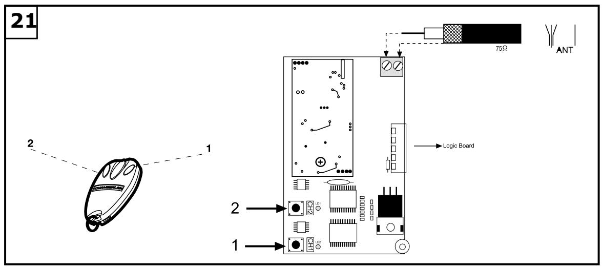
TEACHING THE REMOTE CONTROL
Up to 15 remote controls can be programmed on each self-learn channel. In the case of large installations it is advisable for organizational reasons, to use an external receiver or a key-operated switch or a code lock, which should be installed at the entrance. The radio receiver plugs in on the side and has two small self-learn buttons. The radio remote control is licensed by the Post + Telecommunication Office and costs nothing to operate. It works on the basis of a private security code that is pre-programmed via computer. Your gate/door drive can thus only be activated by a correspondingly coded handset. The range obtained depends on the given local environment. The receiver element of the motor control has an integrated self-learn function. It can be set to the handset's pre-programmed code by pressing the self-learn push-button.
The control unit has two self-learn channels and is therefore able to open or close one gate/door or both gates/doors simultaneously via appropriate operation of the handset. Should, for instance, channel 1 (2) receive the handset's remote control code, only one wing will be opened. If you teach the remote control on channel 2 (1), you will be able to open both wings via the appropriate push-button. To memorize the code all you need do is press the button of your choice on the handset and keep it depressed while, at the same time, briefly pressing the self-learn button on the electronic unit with the other hand. Repeat this procedure for all other transmitters.
DELETION OF REMOTE CONTROL CODE
Press the appropriate self-learn button (1 or 2) on the receiver control board for approx. 10 seconds until the self-learn LED extinguishes. The codes previously 'learned' allocated to the given self-learn button have thus been deleted.
REPROGRAMMING
For reprogramming purposes, the coding procedure mentioned above should be repeated for all the remote controls in use and/or their appropriate operating buttons.
The radio remote control's range varies according to the given local environment. Keep the push-button on the handset depressed until such time (approx. 2 seconds) as the gate/door is seen to move.
Your radio remote control is digitally coded, i.e. accidental operation of the gate/door drive is more or less impossible.
709298-GB-05.2004
INITIAL OPERATION
Proceed carefully and deliberately. Do not rush the process of making the basic settings. It may take up to 30 minutes to complete initial settings. If applicable get help from a second person so that changes on the control unit can be made more easily (power OFF or ON).
Make sure the limit stop cams on the drive are not already pressing against a limit stop. If a limit stop has been activated, the power supply to the drive will be interrupted and the drive won't start. During the course of the following points 1 to 4, you have to find out which limit stop is responsible for which end position. If one motor has been defined, the limit stop sequence for the other motor is the opposite (e.g. if the upper limit stop for the left-hand motor is for gate OPEN, then it is the lower limit stop on the right-hand motor that controls the OPEN position).
Now both limit stops can be set manually such that they cut off the motor in the required positions in both directions. Do not continue with point 5 before this step has been completed.
- Connect the control unit including the safety inputs.
- Check the LEDs.
- Move the gate/door to a half-opened position and engage it, then press the test button. Both wings must then open. If one wing closes instead of opening, the terminals on the given wing's motor have been connected incorrectly and the motor cables for the relevant motor must be swapped round (see connections). The cables to which the capacitor is also connected are the ones that need to be swapped round. They determine the direction in which the motors run. Then repeat the entire process until both wings open when they first move. Important, always switch the power off to do this.
- If both wings open when they first move once the control unit has been connected, proceed as follows.
- Interrupt the power supply to the control unit and reconnect it after a few seconds. Close both gate/door wings manually and engage both wings.
- Adjust all the potentiometers to 30% and make sure that DIP switch 1 is set to OFF (down).
- Then use the test button to switch on the control unit and observe what happens. Close the gate/door again by using the test button WITHOUT having made any adjustments to the settings. If the gate/door does not close completely by itself, release the drive and close it manually after switching off the control unit.
- Then adjust the potentiometer to a different (higher) value in line with the value suggested by practical experience from trial operation (e.g. increase running time, correct force, wing delay). Then make a second trial and repeat the procedure above closing the gate/door first with the test button before making any further settings. The opening time is set with the potentiometer via the maximum running time. The running time should be set 3-5 seconds longer than the time actually needed to ensure that the limit stop is reached even if the wind is blowing against it or in winter. The limit stops on the drive only break the circuit, they do not switch the control unit off! If this is still running in the background, it might be necessary to press the transmitter (or switch) 2x several times to get the gate moving. The first command switches the control unit off, only the second command starts it moving again! The clicking sound of the relays in the control unit tells you when it is has been switched off. The flashing light connected to the control unit means it is much easier to tell if the control unit has been activated or not.
- Once all settings have been made, check that the light barriers, pushbuttons, flashing lamp, handset, accessories etc. function correctly. If you require automatic closing, modify the setting of the DIP switches and adjust the potentiometer for a pause.
- Show anyone who has to deal with the gate/door how the gate/door moves, how the safety functions operate and how the drive can be actuated manually.
FINAL REMARKS
Arrange the handover of the wing gate opener with your customer. Make sure that persons will operate the gate are familiar with its functions and can operate them without problems. Have your customer practice operating the gate until he is fully acquainted with all the following:
- Main switch.
- Rules of operation (e.g. do not drive through while the gate is still opening).
- Additional safety features (photoelectric barrier, contact strip, flashing lights, etc.).
- Switch to manual operation in case of power failure.
- Provide the customer with a full set of instructions. Inform him to keep them in a safe place and read them when possible.
- Reference a checklist, so that you have a record of which functions have been explained and of any points not dealt with.
TECHNICAL DATA
Model ART300K
Mains supply 230V-240V/50
Power consumption 400W
Nominal power 250W
Force max. 350Nm
Nominal load 50Nm
Capacitor 10μF
Temperature -20o to +55^
Frequency Cycles/hr 30%
Weight 1 Motor approx. 9kg
Protection class IP44
Max. door width 3.0m
Max. door weight 250kg
ACCESSORIES
| Model 94335E | 3-channel mini transmitter, 433.92MHz |
| Model 747E | Keypad, 433.92MHz |
| Model 760E | Key switch |
| Model 100027 | 1-Function Keyswitch, surface mount (Flush mount - 100010) |
| Model 100041 | 2-Function Keyswitch, surface mount (Flush mount - 100034) |
| Model 100263 | Infrared barrier |
| Model 203285 | E-Lock 12 Volt |
| Model 203292 | Loop Detector 1 Channel |
| Model 203308 | Loop Detector 2 Channel |
| Model 203315 | Standard Hardstop |
| Model 203322 | Hard Stop High |
| Model 203339 | Mechanical Floor Lock for Double Wings |
| Model 600008 | IR Sensor Stand - 530mm |
| Model 600015 | Key Switch Stand - 1100mm |
| Model 600046 | 2.5 Safety Edge Set (Small) |
| Model 600053 | 20m Bulk Pack Safety Edge Profile (Small) |
| Model 600060 | Assembly Pack Safety Edge (Small) |
| Model 600077 | Bulk pack (not shown) |
| Model 600091 | Main switch |
| Model 600138 | 20m Bulk Pack Safety Edge Profile (Medium) |
| Model 600145 | 20m Bulk Pack Safety Edge Profile (Large) |
| Model 600152 | Assembly Pack Safety Edge (Medium/Large) |
| Model 600169 | 1m (3.2 ft.) Safety Edge Profile (Medium) |
| Model 600176 | 1m (3.2 ft.) Safety Edge Profile (Large) |
| Model 600213 | Interface Box for Safety Edges |
Declaration of Conformity
The undersigned, hereby declare that the equipment specified, and all accessories, conforms to the Directives and Standards stated.
Model: ART300K
EN55014, EN61000-3, EN61000-4, ETS 300 683, EN 300 220-3, EN60335-1, and
EN60335-2-103
89/336/EEC
73/23/EEC
1999/5/EC
Declaration of Incorporation
A power door operator, in combination with a door must be installed and maintained according to all the Manufacturer's instructions, to meet the provisions of Machinery Directive, 89/392/EEC.
B.P.Kelkhoff
Manager, Regulatory Affairs
USA
September, 2003


√ 89/336/EEC
73/23/EEC
√1999/5/EC
B. P. Kelkhoff
Manager, Regulatory Affairs
THE CHAMBERLAIN GROUP, INC.
September, 2003

Baalbasa P.KelkhoH
PER PRIMA COSA LEGGERE QUESTE IMPORTANTI NORME DI SICUREZZAI

B. P. Kelkhoff
Manager, Regulatory Affairs
THE CHAMBERLAIN GROUP, INC.
September, 2003

Baaibaa P.KekkhoH
BEGIN MET HET LEZEN VAN DEZE BELANGRIJKE VEILIGHEIDSINSTRUCTIES!


B. P. Kelkhoff
Manager, Regulatory Affairs
THE CHAMBERLAIN GROUP, INC.
September, 2003
CE Barbara Pekkhoft
COMECE POR LER ESTAS NORMAS DE SEGURANÇA IMPORTANTES


√ 89/336/EEC
√ 73/23/EEC
√ 1999/5/EC
B. P. Kelkhoff
Manager, Regulatory Affairs
THE CHAMBERLAIN GROUP, INC.
September, 2003

Babasa P. Keckhoff
1
2
3
4
5
13
15
16

16
17
Standart = 1x

Aktiv +
Optional = 2x

Aktiv +
18 a

19
Optional = 4x
2x Aktiv + 2x Aktiv
22