
TE-SP 330 - Plane EINHELL - Free user manual and instructions
Find the device manual for free TE-SP 330 EINHELL in PDF.
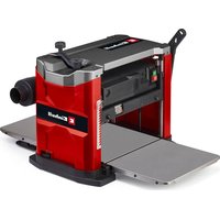


| Product Type | Jointer and thickness planer |
| Brand | Einhell |
| Model | TE-SP 330 |
| Planing width | 330 mm |
| Maximum depth of cut | 3 mm |
| Spindle speed | 8000 rpm |
| Power supply | 230 V / 50 Hz |
| Power consumption | 1500 W |
| Dimensions (L x W x H) | approx. 50 x 40 x 40 cm |
| Weight | approx. 20 kg |
| Main functions | Jointing and thickness planing |
| Depth adjustment | By graduated knob |
| Infeed and outfeed table | Foldable extension tables |
| Dust extraction system | Connection for vacuum cleaner (Diameter 36 mm) |
| Blades | 2 reversible HSS steel blades |
| Maintenance and cleaning | Regularly clean the blades and tables; vacuum chips |
| Safety | Anti-shock safety switch, overload protection |
| Spare parts and repairability | Blades, belt, switch available as spare parts |
| General information | Intended for woodworking; noise level 85 dB(A) |
| Warranty | 2 years (parts and labor) |
Frequently Asked Questions - TE-SP 330 EINHELL
User questions about TE-SP 330 EINHELL
0 question about this device. Answer the ones you know or ask your own.
Ask a new question about this device
Download the instructions for your Plane in PDF format for free! Find your manual TE-SP 330 - EINHELL and take your electronic device back in hand. On this page are published all the documents necessary for the use of your device. TE-SP 330 by EINHELL.
USER MANUAL TE-SP 330 EINHELL
GB Original operating instructions Stationary planer


5
1
1
-7-
D
Danger!
When using the equipment, a few safety precautions must be observed to avoid injuries and damage. Please read the complete operating instructions and safety regulations with due care. Keep this manual in a safe place, so that the information is available at all times. If you give the equipment to any other person, hand over these operating instructions and safety regulations as well. We cannot accept any liability for damage or accidents which arise due to a failure to follow these instructions and the safety instructions.
Explanation of the symbols used (see Fig. 18)
- Danger! - Read the operating instructions to reduce the risk of injury.
- Caution! Wear ear-muffs. Noise can cause loss of hearing.
- Caution! Wear a breathing mask. Dust which is harmful to health can be generated when machining wood and other materials. Never use the machine to work on materials containing asbestos!
- Caution! Wear safety goggles. Sparks, splinters, chips and dust emitted by the machine can cause loss of sight.
- Overload switch
- Caution! Risk of injury! Never reach into the planing knife during operation.
- Direction of rotation of the knife shaft.
- Turn the crank clockwise for a bigger thickness opening. Turn the crank counter-clockwise for a smaller thickness opening. One 360° rotation of the crank is equivalent to a change in height of 2 mm.
- Conditions of the mains connection
- Power rating
- Speed
1. Safety regulations
The corresponding safety information can be found in the enclosed booklet.
WARNING!
Read all safety warnings, instructions, illustrations and specifications provided with this power tool. Failure to follow all instructions listed below may result in electric shock, fire and/or serious injury.
Save all warnings and instructions for future reference.
This machine is not intended to be used by persons (including children) with reduced physical, sensory or mental capacities or those with a lack of experience and/or knowledge. Children must always be supervised in order to ensure that they do not play with the tool.
2. Layout and items supplied
2.1 Layout (Fig. 1-17)
- On/Off switch
- Transport handle
- Push stick
- Crank arm
- Extractor port
- Extractor adapter
- Clamp lever
- Fastening hole
- Feed roller
- Discharge roller
- Screw for crank
- Bar
- Feed table
- Discharge table
- Setting gauge
- 4 mm hex key
- Open-ended wrench
- Scale for cutting depth
- Pointer for cutting depth
- Planing table
- Planing knife
- Slotted bar
- Knife shaft
- Anti-kick claws
- Tensioning screw
- Spring
- Socket head screws
- Suspension lugs
- Scale for thickness opening
- Pointer for thickness opening
- Planing unit
- Scale on the hand crank
- Pointer for the hand crank
- Stop screw
- Lock nut
- Overload switch
- Depth stop
- Cover
- Fastening screw for the cover
- Support area
- Boundary area
- Power cable
- Cable holder
GB
2.2 Items supplied
Please check that the article is complete as specified in the scope of delivery. If parts are missing, please contact our service center or the sales outlet where you made your purchase at the latest within 5 working days after purchasing the product and upon presentation of a valid bill of purchase. Also, refer to the warranty table in the service information at the end of the operating instructions.
- Open the packaging and take out the equipment with care.
- Remove the packaging material and any packaging and/or transportation braces (if available).
- Check to see if all items are supplied.
- Inspect the equipment and accessories for transport damage.
- If possible, please keep the packaging until the end of the guarantee period.
- Workpieces might kick back if the machine is used incorrectly.
- Damage to hearing and eye injuries plus injuries to fingers and hands if the required protective equipment is not used.
- Harmful emissions when used in enclosed spaces without a suitable extractor system.
The equipment is to be used only for its prescribed purpose. Any other use is deemed to be a case of misuse. The user / operator and not the manufacturer will be liable for any damage or injuries of any kind caused as a result of this.
Please note that our equipment has not been designed for use in commercial, trade or industrial applications. Our warranty will be voided if the machine is used in commercial, trade or industrial businesses or for equivalent purposes.
Danger!
The equipment and packaging material are not toys. Do not let children play with plastic bags, foils or small parts. There is a danger of swallowing or suffocating!
• Stationary planing machine - Push stick Crank arm - Extractor port - Extractor adapter - Setting gauge - 4 mm hex key - Open-ended wrench • Original Operating Instructions • Safety Information
4. Technical data
AC motor: 220-240V \~ 50/60 Hz
Power P: 1,800 W
Max. workpiece width 330 mm
Max. workpiece height at thickness opening: .....
153 mm
Workpiece length: ....min. 280 mm
Thicknessing table: 860 x 330 mm
Thicknessing feed speed: 8.4 m/min
Motor idle speed n0: 22,000 min-1
Planing knife idle speed: 10,000 min-1
Max. cutting depth: 3 mm
Sawdust extractor: 0 100 / 63.5 mm
Protection class: ....
Weight: approx. 35 kg
3. Proper use
The planing machine is designed for thicknessing all types of sawn timber.
The machine is allowed to be used only for its prescribed purpose.
Even when the machine is used as prescribed it is still impossible to eliminate certain residual risk factors. There is a risk of the following injuries in connection with the required operation of the machine.
- Fingers or hands coming into contact with the knife shaft in areas which are out of view.
Danger!
Sound and vibration
Sound and vibration values were measured in accordance with EN 61029.
Sound pressure level LdA 94 dB(A)
Uncertainty KpA 3 dB(A)
Sound power level LWA .....105dB(A)
Uncertainty KWA 3 dB(A)
Wear ear-muffs.
Noise can cause loss of hearing.
GB
The quoted vibration value was measured in accordance with a standardized testing method. It might change according to how the electric tool is used, and in exceptional circumstances it might exceed the quoted value.
The quoted vibration value can be used to compare one electric tool with another.
The quoted vibration value can also be used for initial assessment of a harmful effect.
Keep the noise emissions and vibrations to a minimum.
- Only use appliances which are in perfect working order. • Service and clean the appliance regularly. • Adapt your working style to suit the appliance. • Do not overload the appliance.
- Have the appliance serviced whenever necessary.
- Switch the appliance off when it is not in use.
Caution!
Residual risks
Even if you use this electric power tool in accordance with instructions, certain residual risks cannot be ruled out. The following hazards may arise in connection with the equipment's construction and layout:
- Lung damage if no suitable protective dust mask is used.
- Damage to hearing if no suitable ear protection is used.
5. Before using for the first time
- Warning! Pull out the power plug before performing any maintenance, cleaning and adjusting work. • Always wear eye protection. • Regularly check that the planing knife (21) is securely seated in the knife shaft (23).
- The knife shaft (23) must be able to rotate freely.
- Check the anti-kick claws (24) to ensure that they are in perfect working order. The claws must be able to move easily so they are freely suspended pointing downwards.
- Visually check that the feed roller (9) and the discharge roller (10) run uniformly.
- Before you press the On/Off switch (1), make sure that the planing knife is fitted correctly
and that the machine's moving parts run smoothly.
- Never remove the safety covers on the machine except for servicing and repair work.
- The safety covers must be intact at all times. Each time you use the machine, first fasten and secure the safety covers at the points provided.
- All covers and safety devices must be properly fitted before the machine is switched on.
- Never cut concavities, tenons or shapes.
- When working with wood that has been previously processed, watch out for foreign bodies such as nails or screws, etc. • Unpack the planing machine and check it for damage which might have occurred in transit.
- The machine must be set up and aligned where it can stand securely.
- If you want to machine heavy or long workpieces, firmly screw the machine to a workbench or similar using the mounting holes (8).
- To work on long workpieces, use roller tables or a similar supporting arrangement. Such optional units are available from your local DIY stores. They must be placed at the entry and exit ends of the planing machine. Their height must be adjusted such that the workpiece is horizontal when it is fed into and out of the machine.
- Check that the voltage on the rating plate is the same as your supply voltage before you connect the machine to the power supply.
5.1 Assembly (Fig. 3)
- Remove the screw (11) from the bar (12) using the hex key (16).
- Fit the crank (4) on the bar (12). Fasten it with the screw (11).
5.2 Vacuum extractor (Fig. 4)
- Check that the three socket head screws (27) have been slackened by a few revolutions.
- Hang the extraction socket (5) on the three top lugs (28). Secure the extraction socket (5) by tightening the socket head screws (27) with the hex key (16).
- Connect a vacuum extraction system to the extraction socket (5) (refer to the technical data for the diameter).
- You can reduce the diameter of the extractor connection by fitting the extractor adapter (6) to the extraction socket (5). Alternatively you can connect a vacuum extraction system to the extractor adapter (6).
5.3 Storing the loose parts (Fig. 1/5)
- When not in use, the push stick (3) can be stored ready-to-hand on the machine as shown in Fig. 1.
- The setting gauge (15), the open-ended wrench (17) and the hex key (16) can all be fastened to the machine as shown in Fig. 5.
6. Operation
6.1 Thickness opening (Fig. 6)
Turn the crank (4) to set the planing unit (31) to the required thickness opening.
- Turn clockwise: This will make the thickness opening larger by raising the planing unit.
- Turn counter-clockwise: This will make the thickness opening smaller by lowering the planing unit.
- Turn the crank (4) until the pointer (30) coincides with the desired dimension setting on the scale (29).
- Lock the thickness opening by swinging the clamping lever (7) to the right.
6.2 Cutting depth (Fig. 7)
The cutting depth of the planing knife (21) can be read off the scale (18).
• Slacken the clamping lever (7). - With the planing machine switched off, guide your workpiece into the planing machine far enough for the pointer (19) to move. - Important! The position of the button for indicating the cutting depth is marked with an arrow (see Fig. 7). - Turn the crank (4) until the pointer (19) coincides with the desired cutting depth setting on the scale (18). - Retighten the clamp lever (7) and remove the workpiece.
6.3 Making several passes to reach the final dimension (Fig. 3, 6, 7)
- As a general rule, the following applies: You can increase the surface quality and reduce the load on the planing machine by performing several passes with smaller cutting depths.
- For the first planing pass you should select a small cutting depth so that any unevenness in the workpiece does not result in the maximum cutting depth being exceeded (see "Technical data") and in the workpiece being blocked.
- With the help of the scale (32) on the crank (4) you can reduce the cutting depth for further passes true to size.
- Turn the scale (32) on the hand crank (4) until "0" and the pointer (33) coincide. • Slacken the clamping lever (7).
- Turn the crank (4) one quarter of a revolution counter-clockwise in order to set the cutting depth to 0.5 mm. If you want to achieve a cutting depth of 1 mm, turn the crank (4) one half of a revolution etc. • Retighten the clamping lever (7).
6.4 Table width extensions (Fig. 8)
To ensure optimum results you must align the table width extensions so that they are level with the planing table (20).
- Check this with a straight object such as a ruler, wood with a straight edge, etc. • If necessary you can adjust the feed table (13) and the discharge table (14).
- Swing up the feed table (13) and the discharge table (14). Slacken the lock nuts (35) using the open-ended wrench (17).
- Swing the feed table (13) and the discharge table (14) back out again. Now turn the stop screws (34) to the point where the table width extensions are aligned parallel to the surface of the planing table (20).
- Retighten the lock nuts (35) using the open-ended wrench (17).
6.5 Depth stop (Fig. 9)
Use the depth stop (37) to plane workpieces repeatedly to a uniform thickness. This is helpful in particular when you occasionally machine different workpiece thicknesses.
• Slacken the clamping lever (7). • Using the crank (4), raise the planing unit (31) to at least 32 mm. - Turn the depth stop (37) to the required thickness. (Selectable dimensions: 6, 12, 19, 25 or 31 mm) - Using the crank (4), lower the planing unit (31) until the planing unit (31) rests on the depth stop (37). - Secure the height setting with the clamping lever (7). - When you are not using the depth stop (37) it must be set to 0 mm.
7. Operation
7.1 On/Off switch (Fig. 1, 10 / Item 1)
- To turn the planing machine on, press the green button "I". Wait for the knife shaft to reach its maximum speed of rotation before you begin to plane.
- To turn the planing machine off again, press the red button "0".
The motor of this machine is protected against overload by an overload switch (36). If the rated current is exceeded, the overload switch (36) will shut down the machine.
- Let the machine cool down for several minutes. Press the overload switch (36).
- Press the green button "I" to switch on the machine.
7.2 Thicknessing (Fig. 7, 11)
- The contact surface of the workpiece must be flat on the planing table (20) for thicknessing.
- In the case of long workpieces, make sure there is sufficient room on the discharge side of the planing machine.
- Set the cutting depth as described in 6.2 and 6.3.
- Press the green button "I" to switch on the planing machine.
- Lay the workpiece on the feed table (13) and guide it in horizontally. The workpiece will be caught by the feed roller (9) and be drawn in automatically.
- Remove the workpiece from the discharge table (14) once the discharge roller (10) no longer grips the workpiece.
- Readjust the cutting depth and repeat the operation until the workpiece has its required final thickness.
- Warning! Risk of kick-back. To ensure safe guidance of the workpiece, never go below the recommended minimum workpiece length (see "Technical data").
- Switch off the planing machine before you leave your workplace.
If the planing machine becomes blocked during use, proceed as follows:
- Switch off the planing machine immediately. • Slacken the clamping lever (7).
- Raise the planing unit (31) until the anti-kick claws (24) no longer touch the workpiece.
- Remove the workpiece from the planing machine.
- Repeat the planing operation but with a smaller cutting depth.
8. Changing the knife
8.1 Notes on changing the knife
- Warning! Always pull the mains plug before changing the knives.
- Warning! To prevent injury, wear gloves when changing the knife!
- In its original condition the planing machine is equipped with two reversible knives. When the planing knives (21) become worn, they can be reversed; there is a cutting edge on both the front and the back side.
- You must always replace/renew both planing knives (21). Planing knives (21) must always be replaced in pairs or be sharpened in identical manner.
- Warning! Planing knives (21) of different width will result in imbalance, damaged bearings, and a greater risk of kick-back!
- The knives (21) are allowed to project by no more than 1.1 mm above the surface of the knife shaft (23).
- Only use knives which are recommended by the manufacturer for this machine. If you use other knives there is a risk of injuries due to lack of control.
- Warning! To change the knives, use only the setting gauge (15) supplied with the machine.
- Avoid over-tightening and the possibility of the thread becoming detached. If the slotted bar (22) or the tightening screws (25) have worn out threads, they must be replaced immediately!
8.2 Changing a knife (Fig. 12-15)
Use the crank to lower the planing unit (31) to the very bottom (see 6.1).
- Remove the extraction socket (5) (see 5.2).
- Use the hex key (16) to undo the two fastening screws (39) in the cover (38).
- Remove the cover (38) to provide access to the knife shaft (23).
- Slacken the planing knife (21) by turning the tightening screws (25) clockwise.
- Turn in the tightening screws (25) far enough to be able to remove the planing knife (21) and the slotted bar (22).
- Carefully clean the planing knife (21), the slotted bar (22), the knife shaft (23) and the springs (26). While you are assembling the parts, make sure there is no resin on any of the parts.
- Reinsert both springs (26) in the holes in the knife shaft (23).
- Reinsert the slotted bar (22) and the new planing knife (21) in the knife shaft (23).
- Warning! Risk of kick-back. Note the direction of rotation of the knife shaft (23) (see the symbol on the side of the housing). The cutting angle of the planing knife (21) must point in the direction of rotation.
- Align the planing knife (21) centrally with the knife shaft (23).
- Turn out the tightening screws (25) to the point where the planing knife no longer slips but can still be moved with a little force. • Fit the setting gauge (15) on the knife shaft (23).
- Make sure that the support surfaces (40) lie on the knife shaft (23). The left and right boundary area (41) should now touch the cutting edge of the planing knife (21). Use the setting gauge (15) to position the planing knife (21).
- Use the open-ended wrench (17) to tighten the tightening screws (25).
- Warning! To avoid subjecting the planing knife (21) to any tension, tighten the tightening screws (25) from the inside to the outside. First tighten the middle tightening screw and then the next pair of tightening screws in outward direction.
- Repeat this procedure for the second planing knife (21). • Refit the cover (38) and the extractor port (5).
9. Replacing the power cable
Danger!
If the power cable for this equipment is damaged, it must be replaced by the manufacturer or its after-sales service or similarly trained personnel to avoid danger.
10. Cleaning, maintenance and ordering of spare parts
Danger!
Always pull out the mains power plug before starting any cleaning work.
10.1 Cleaning
- Keep all safety devices, air vents and the motor housing free of dirt and dust as far as possible. Wipe the equipment with a clean cloth or blow it with compressed air at low pressure.
- We recommend that you clean the device immediately each time you have finished using it.
- Clean the equipment regularly with a moist cloth and some soft soap. Do not use cleaning agents or solvents; these could attack the plastic parts of the equipment. Ensure that no water can seep into the device. The ingress of water into an electric tool increases the risk of an electric shock.
10.2 Maintenance (Fig. 1/16)
Warning! Pull out the mains plug before starting any maintenance work.
10.2.1 The machine (Fig. 16)
After approx. 10 hours in operation, lubricate all the positions indicated in Fig. 16. Use only dry lubricant.
The feed table (13), the discharge table (14), the planing table (20), the feed rollers (9) / discharge rollers (10), and the anti-kick claws (24) must be kept free of resin at all times. Soiled feed rollers (9) / discharge rollers (10) or anti-kick claws (24) must be cleaned without delay.
To prevent the motor overheating, the dust that accumulates in the ventilation openings must be removed at regular intervals.
Improve the smooth running of the tables by applying lubricant at regular intervals.
10.2.2 Cutting tool
Resin must be cleaned off the knife (21), the slotted bar (22) and the knife shaft (23) at regular intervals. Clean these components with an appropriate resin remover.
10.3 Ordering replacement parts:
Please quote the following data when ordering replacement parts:
• Type of machine • Article number of the machine • Identification number of the machine
- Replacement part number of the part required For our latest prices and information please go to www.Einhell-Service.com
10.4 Transport (Fig. 17)
- Caution! Make allowance for the weight of the machine and arrange for another person to help you if necessary.
- Remove the extractor port (5) as described in 5.2.
- Swing up the feed table (13) and the discharge table (14).
- Attach the power cable (42) to the cable holder (43). • Stow away all loose parts as described in 5.3.
- Transport the machine by lifting it only by the transport handles (2).
- Never use the guards for handling or transporting purposes.
11. Disposal and recycling
The equipment is supplied in packaging to prevent it from being damaged in transit. The raw materials in this packaging can be reused or recycled. The equipment and its accessories are made of various types of material, such as metal and plastic. Never place defective equipment in your household refuse. The equipment should be taken to a suitable collection center for proper disposal. If you do not know the whereabouts of such a collection point, you should ask in your local council offices.
12. Storage
Store the equipment and accessories in a dark and dry place at above freezing temperature. The ideal storage temperature is between 5 and 30 °C. Store the electric tool in its original packaging.
13. Possible causes of failure
| Problem Cause Solution | ||
| The planing machine does not start. | 1. No supply voltage.2. Insufficient mains voltage.3. The motor is too hot.4. The carbon brushes are worn. | 1. Check the cable, power plug, fuse and socket-outlet.2. Make sure that the extension cable is not too long. Use an extension cable with a large enough wire cross-section.3. Allow the motor to cool down. If necessary, remedy the cause of the overheating and actuate the overload switch (36).4. Have the carbon brushes replaced by an electrician. |
| Loss of speed in planing mode / The machine becomes blocked in planing mode. | 1. Cutting depth too deep.2. Blunt knives. | 1. Reduce the cutting depth.2. Renew the planing knives (21). |
| Poor surface quality of the planed workpiece. | 1. Blunt knives.2. Uneven feed.3. A vacuum extraction system (not supplied) is not connected. | 1. Renew the planing knives (21).2. Clean the feed roller (9), the discharge roller (10), the planing table (20), the feed table (13) and the discharge table (14).3. Connect up a vacuum extraction system. |
| The chip ejector is blocked. | 1. Vacuum extraction system (not supplied) is not connected.2. Wood too wet. | 1. Connect up a vacuum extraction system.2. Use dry wood |
GB
Disposal

Power tools, rechargeable batteries, accessories and packaging should be sorted for environmental-friendly recycling.
Do not dispose of power tools and batteries/rechargeable batteries into household waste!
Only for EU countries:
According to the Directive 2012/19/EU on waste electrical and electronic equipment and its transposition into national law, power tools that are no longer usable, and, according to the Directive 2006/66/EC, defective or drained batteries must be collected separately and disposed of in an environmentally correct manner.
If disposed incorrectly, waste electrical and electronic equipment may have harmful effects on the environment and human health, due to the potential presence of hazardous substances.
Only for United Kingdom:
According to The Waste Electrical and Electronic Equipment Regulations 2013 (SI 2013/3113) (as amended) and the Waste Batteries and Accumulators Regulations 2009 (SI 2009/890) (as amended), products that are no longer usable must be collected separately and disposed of in an environmentally friendly manner.
The reprinting or reproduction by any other means, in whole or in part, of documentation and papers accompanying products is permitted only with the express consent of the Einhell Germany AG.
Subject to technical changes.
- The product meets the requirements of EN 61000-3-11 and is subject to special connection conditions. This means that use of the product at any freely selectable connection point is not allowed.
- Given unfavorable conditions in the power supply the product can cause the voltage to fluctuate temporarily.
- The product is intended solely for use at connection points that a) do not exceed a maximum permitted supply impedance, or b) have a continuous current-carrying capacity of the mains of at least 100 A per phase.
- As the user, you are required to ensure, in consultation with your electric power company if necessary, that the connection point at which you wish to operate the product meets one of the two requirements, a) or b), named above.
GB
Service information
We have competent service partners in all countries named on the guarantee certificate whose contact details can also be found on the guarantee certificate. These partners will help you with all service requests such as repairs, spare and wearing part orders or the purchase of consumables.
Please note that the following parts of this product are subject to normal or natural wear and that the following parts are therefore also required for use as consumables.
| Category Example | |
| Wear parts* V-belt / drive rollers | |
| Consumables* Planing knife | |
| Missing parts |
* Not necessarily included in the scope of delivery!
In the event of defects or faults, please register the problem on the internet at www.Einhell-Service.com. Please ensure that you provide a precise description of the problem and answer the following questions in all cases:
• Did the equipment work at all or was it defective from the beginning? • Did you notice anything (symptom or defect) prior to the failure? • What malfunction does the equipment have in your opinion (main symptom)? Describe this malfunction.
GB
Warranty certificate
Dear Customer,
All of our products undergo strict quality checks to ensure that they reach you in perfect condition. In the unlikely event that this equipment develops a fault, please contact our service department at the address shown on this guarantee card. You can also contact us by telephone using the service number shown. Please note the following terms under which guarantee claims can be made:
- These guarantee terms apply solely to consumers, i.e. natural persons, who do not want to use this product in connection with either their commercial or other self-employed activities. These guarantee terms regulate additional guarantee services which the undermentioned manufacturer promises to buyers of its new products in addition to their statutory rights of guarantee. Your statutory rights of guarantee are not affected by this guarantee. Our guarantee is free of charge to you.
- The guarantee services cover only defects due to material or manufacturing faults on the new product which you have bought in the European Union from the undermentioned manufacturer and are limited to either the rectification of said defects or the replacement of the product, whichever we prefer. Please note that only equipment under the brand name "Professional" has been designed for use in commercial, trade or professional applications. For all other products the guarantee is invalidated if the equipment is used within the guarantee period in commercial, trade or industrial applications or for other equivalent activities.
- Our guarantee does not cover:
- Damage to the equipment caused by failure to comply with the installation/assembly instructions or by unprofessional installation; damage caused by failure to comply with the operating instructions (e.g. connection to the wrong mains voltage or current type); damage caused by failure to comply with the maintenance and safety regulations; damage caused by exposing the equipment to abnormal environmental conditions; damage resulting from poor care and maintenance.
- Damage to the equipment caused by misuse or incorrect applications (e.g. overloading the equipment or using non-approved attachments or accessories); damage caused by foreign bodies (e.g. sand, stones, dust, ....) getting inside the equipment. Damage in transit; damage caused by force or external influences (e.g. by dropping the equipment).
- Damage to the equipment or parts of the equipment which is owed to use-related, normal or otherwise natural wear. For example, batteries and battery packs are manufactured with a cycle limit for design-related reasons. Wear is negatively influenced in particular by load demands and charging speeds as well as exposure to heat, cold, vibration and impact.
- The guarantee is valid for a period of 2 years starting from the purchase date of the equipment. Guarantee claims must be submitted before the end of the guarantee period and within two weeks of the defect being noticed. No guarantee claims will be accepted after the end of the guarantee period. The original guarantee period remains applicable to the equipment even if repairs are carried out or parts are replaced. In such cases, the work performed or parts fitted will not result in an extension of the guarantee period, and no new guarantee will become active for the work performed or for any replacement parts fitted. This also applies if on-site service is used.
- To assert your guarantee claim, register the defective equipment at: www.Einhell-Service.com. You will need to provide proof of purchase of the new item of equipment. Equipment returned without such proof or without a rating plate are excluded from the guarantee services because of the lack of traceability. If the defect is covered by our guarantee, then either the item in question will be repaired immediately and returned to you or we will send you a new replacement.
- If you have taken the equipment with you to a different EU country than where you bought it, we will arrange for a local service partner to provide the guarantee services. If you take the equipment outside the EU, the guarantee will not apply.
Of course, we are also happy to offer a chargeable repair service for any defects which are not covered or no longer covered by the scope of this guarantee. To take advantage of this service, please send the equipment to our service address. We draw attention to the restrictions of this guarantee concerning wear parts, consumables and missing parts as presented in the service information included in this operating manual.
Warrantor/ Service:
Einhell UK Ltd, Unit 10, 1st Floor, Champion's Business Park, Arrowe Brook Road, Upton, Wirral, CH49 0UQ
F
Danger!
5.2 Aspiration (figure 4)
10.4 Transport (figure 17)
10.4 Transport (figure 17)
Uncertainty KpA 3 dB(A)
Sound power level LWA 105 dB(A)
SLO
Uncertainty KWA 3 dB(A)
X 2006/42/EC X Annex IV Notified Body:
TÜV Rheinland LGA Products GmbH, Tillystraße 2, 90431 Nürnberg (Notified Body No.: 0197) BM 50520206 0001
00/14/EC_2005/88/EC
□ Annex V
Annex VI
Noise: measured Lw0 = dB (A) ; guaranteed Lw3 = dB (A)
P = KW; L/∅ = cm
Notified Body:
□2012/46/EU_(EU)2016/1628
Emission No.:
Standard references: EN 61029-1; EN 61029-2-3;
EN IEC 55014-1; EN IEC 55014-2; EN IEC 61000-3-2; EN IEC 61000-3-11
Subject to change without notice
Archive-File/Record: NAPR018111
Documents registrar: Korbinian Wasmeier
Wiesenweg 22, D-94405 Landau/Isar
* GR Stationery planar - FL Batone stationaire - FL Statione a spesora - OKW Stationer hawabotiva - S Statione hyel - CZ Stationi hohobka - SK Stationema hohobaka - ML Statione staachmacin. - EC Pediladora stationaria - FN Oikotaschlyd - SL Stationari stroj e skojatyja - H Stationeri gyalugta - RO Magina de rhesol stationara - GR Statador nátkapri plano - PL Plasma de mesa - HR/BN Stationera slarjatica - RS Stationaro ronde - PL Wyndemiano - grubscicola - TR Targeti Paraya - RUS Staikanariar strpcaprial stanica - EE Statadana hohobalink - LV Statonaria hovimatis - LT Stationari ombimo masla - BO Afixri - UKF Staikanariar tokarhini berpata - MK Saitinien ctrup

Declaration of conformity
We, Einhell UK Ltd
Champions Business Park, First Floor Unit 10, Arrowe Brook Rd, Upton, Wirral CH49 0AB, United Kingdom
declare the conformity to UK standards and legislation was assessed for:
Thicknesser TE-SP 330 (Einhell)
UK legislation
□ Simple Pressure Vessels (Safety) Regulation □ Electrical Equipment (Safety) Regulation □ Radio Equipment Regulation □ Personal Protective Equipment Regulation ☐ The Ecodesign for Energy-Related Products and Energy Information Regulation X The Restriction of the Use of Certain Hazardous Substances in Electrical and Electronic Equipment Regulation □ Noise Emission in the Environment by Equipment for use Outdoors Regulation X Electromagnetic Compatibility Regulation □ Measuring Instruments Regulation □ Pressure Equipment (Safety) Regulation
Annex V
Annex VI
Noise: measured L WA = dB (A); guaranteed L WA = dB (A) P = kW; L/∅ = cm Approved Body: 1
X Supply of Machinery (Safety) Regulation
X Annex IV
Approved Body: TÜV Rheinland LGA Products GmbH, Tillystraße 2, 90431 Nürnberg (Notified Body No.: 0197)
Certificate No.: BM 50520206 0001
ße 2, 90431 Nürnberg (Notified Body No.: 0197)
Wirral, 2023.10.17

Archive-File/Record: NAPR018111
Article Number: 44.199.25 I.-No.: 11019
Subject to change without notice Wiesenweg 22, 94405 Landau/Isar, Germany
Documents registrar: Korbinian Wasmeier
EH 01/2024 (01)



- D
- DANGER
- EXPLANATION OF THE SYMBOLS USED (SEE FIG. 18)
- SAFETY REGULATIONS
- WARNING
- LAYOUT AND ITEMS SUPPLIED
- LAYOUT (FIG. 1-17)
- GB
- ITEMS SUPPLIED
- TECHNICAL DATA
- PROPER USE
- THE MACHINE IS ALLOWED TO BE USED ONLY FOR ITS PRESCRIBED PURPOSE
- SOUND AND VIBRATION
- WEAR EAR-MUFFS
- KEEP THE NOISE EMISSIONS AND VIBRATIONS TO A MINIMUM
- CAUTION
- RESIDUAL RISKS
- BEFORE USING FOR THE FIRST TIME
- ASSEMBLY (FIG. 3)
- VACUUM EXTRACTOR (FIG. 4)
- STORING THE LOOSE PARTS (FIG. 1/5)
- OPERATION
- THICKNESS OPENING (FIG. 6)
- CUTTING DEPTH (FIG. 7)
- MAKING SEVERAL PASSES TO REACH THE FINAL DIMENSION (FIG. 3, 6, 7)
- TABLE WIDTH EXTENSIONS (FIG. 8)
- DEPTH STOP (FIG. 9)
- ON/OFF SWITCH (FIG. 1, 10 / ITEM 1)
- THICKNESSING (FIG. 7, 11)
- CHANGING THE KNIFE
- NOTES ON CHANGING THE KNIFE
- CHANGING A KNIFE (FIG. 12-15)
- REPLACING THE POWER CABLE
- CLEANING, MAINTENANCE AND ORDERING OF SPARE PARTS
- CLEANING
- MAINTENANCE (FIG. 1/16)
- THE MACHINE (FIG. 16)
- CUTTING TOOL
- ORDERING REPLACEMENT PARTS
- TRANSPORT (FIG. 17)
- DISPOSAL AND RECYCLING
- STORAGE
- POSSIBLE CAUSES OF FAILURE
- DISPOSAL
- ONLY FOR EU COUNTRIES
- ONLY FOR UNITED KINGDOM
- SERVICE INFORMATION
- WARRANTY CERTIFICATE
- F
- ASPIRATION (FIGURE 4)
- TRANSPORT (FIGURE 17)
- SLO
- DECLARATION OF CONFORMITY
- THICKNESSER TE-SP 330 (EINHELL)
- UK LEGISLATION
Brand : EINHELL
Model : TE-SP 330
Category : Plane