
MONOTRIBE - Analog synthesizer KORG - Free user manual and instructions
Find the device manual for free MONOTRIBE KORG in PDF.
| Product type | Analog synthesizer |
| Brand | KORG |
| Model | MONOTRIBE |
| Dimensions (W × D × H) | 207 × 145 × 70 mm |
| Weight | 735 g (without batteries) |
| Power supply | 6 AA/LR6 alkaline or NiMH batteries, or DC9V AC adapter (sold separately) |
| Battery life | Approximately 14 hours with alkaline batteries |
| Sound generator | Analog synthesis: 1 VCO (sawtooth, triangle, square), noise generator, 1 VCF (low-pass 12dB/oct), 1 VCA, 1 LFO |
| Drum section | 3 parts (bass drum, snare drum, hi-hat), separate analog circuits |
| Sequencer | 8 steps, real-time recording, FLUX mode |
| Keyboard | Ribbon keyboard with WIDE/NARROW ranges, chromatic playing |
| Connectors | AUDIO IN (3.5 mm stereo mini-jack), OUTPUT (6.3 mm stereo unbalanced jack), HEADPHONES (3.5 mm stereo mini-jack), SYNC IN/OUT (3.5 mm mono mini-jack) |
| Built-in speaker | Yes |
| Main functions | Analog synthesis, 8-step sequencer, 3-part analog drum section, ribbon keyboard, FLUX mode, multi-function LFO, automatic tuning, external audio input, built-in speaker |
| Maintenance and cleaning | Clean with a clean, dry cloth. Do not use benzene, thinner, or flammable products. |
| Safety | Do not place liquid containers nearby; avoid intrusion of metal objects. Disconnect power in case of trouble and contact a Korg dealer. |
| Spare parts and repairability | Contact the nearest Korg dealer or the store of purchase. |
| General information | KORG MONOTRIBE analog synthesizer. Manual available in multiple languages at notice-facile.com. |
Frequently Asked Questions - MONOTRIBE KORG
User questions about MONOTRIBE KORG
0 question about this device. Answer the ones you know or ask your own.
Ask a new question about this device
Download the instructions for your Analog synthesizer in PDF format for free! Find your manual MONOTRIBE - KORG and take your electronic device back in hand. On this page are published all the documents necessary for the use of your device. MONOTRIBE by KORG.
USER MANUAL MONOTRIBE KORG
How the sound generator is structured 5
The three elements of sound (pitch, timbre, and volume) 5
Block diagram 6
Getting started 7
7
Using an AC adapter 7
Battery level indication 7
Connections 8
Turning the power on 9
Turning the power off 9
Auto power-off 9
Panel description and functions 10
Synthesizer section 10
Sequencer section 13
Global menu 16
Setting procedure 16
Specifications 17
Thank you for purchasing the Korg monotribe analogue ribbon station.
To help you get the most out of your new instrument, please read this manual carefully.
Precautions
Location
Using the unit in the following locations can result in a malfunction.
In direct sunlight
- Locations of extreme temperature or humidity
- Excessively dusty or dirty locations
- Locations of excessive vibration
- Close to magnetic fields
Power supply
Please connect the designated AC adapter to an AC outlet of the correct voltage. Do not connect it to an AC outlet of voltage other than that for which your unit is intended.
Interference with other electrical devices
Radios and televisions placed nearby may experience reception interference.
Operate this unit at a suitable distance from radios and televisions.
Handling
To avoid breakage, do not apply excessive force to the switches or controls.
Care
If the exterior becomes dirty, wipe it with a clean, dry cloth. Do not use liquid cleaners such as benzene or thinner, or cleaning compounds or flammable polishes.
Keep this manual
After reading this manual, please keep it for later reference.
Keeping foreign matter out of your equipment
Never set any container with liquid in it near this equipment. If liquid gets into the equipment, it could cause a breakdown, fire, or electrical shock.
Be careful not to let metal objects get into the equipment. If something does slip into the equipment, unplug the AC adapter from the wall outlet. Then contact your nearest Korg dealer or the store where the equipment was purchased.
Notice regarding disposal (EU only)

When this "crossed-out wheeled bin" symbol is displayed on the product, owner's manual, battery, or battery package, it signifies that when you wish to dispose of this product, manual, package or battery you must do so in an approved manner. Do not discard this product, manual, package or battery along with ordinary household waste. Disposing in the correct manner will prevent harm to human health and potential damage to the environment. Since the correct method of disposal will depend on the applicable laws and regulations in your case, please contact your local administrative body for details. If the battery has heavy metals in excess of the regulated amount, a chemical symbol is layed below the "crossed-out wheeled bin" symbol on the battery or package.
THE FCC REGULATION WARNING (for USA)
This equipment has been tested and found to comply with the limits for a Class B digital device, pursuant to Part 15 of the FCC Rules. These limits are designed to provide reasonable protection against harmful interference in a residential installation. This equipment generates, uses, and can radiate radio frequency energy and, if not installed and used in accordance with the instructions, may cause harmful interference to radio communications. However, there is no guarantee that interference will not occur in a particular installation. If this equipment does cause harmful interference to radio or television reception, which can be determined by turning the equipment off and on, the user is encouraged to try to correct the interference by one or more of the following measures:
- Reorient or relocate the receiving antenna.
- Increase the separation between the equipment and receiver.
- Connect the equipment into an outlet on a circuit different from that to which the receiver is connected.
- Consult the dealer or an experienced radio/TV technician for help. Unauthorized changes or modification to this system can void the user's authority to operate this equipment.
IMPORTANT NOTICE TO CONSUMERS
This product has been manufactured according to strict specifications and voltage requirements that are applicable in the country in which it is intended that this product should be used. If you have purchased this product via the internet, through mail order, and/or via a telephone sale, you must verify that this product is intended to be used in the country in which you reside.
WARNING: Use of this product in any country other than that for which it is intended could be dangerous and could invalidate the manufacturer's or distributor's warranty.
Please also retain your receipt as proof of purchase otherwise your product may be disqualified from the manufacturer's or distributor's warranty.
Main features
Analog synthesis
The VCO, VCF, and VCA are constructed of analog circuitry. With intuitively simple operation and the sound-creating process that's distinctive of analog synthesizers, the monotribe gives you a flexible and highly improvisatory synthesis experience. The VCF features the filter circuit of the classic Korg MS-20.
Self-tuning function
When not producing sound, the monotribe tunes itself internally to correct any pitch drift that may occur due to temperature changes or aging. Despite the analog VCO, the monotribe does not require regular servicing to stay in tune over time; the monotribe can deliver reliable performance as soon as the power is turned on.
Ribbon keyboard
You can switch the pitch range of the ribbon keyboard (WIDE/NARROW). Since it can also be played chromatically like a conventional keyboard, you'll be able to play melodies with accurate pitches.
Analog drum sound generator
A crisp-sounding three-part drum sound generator using discrete analog circuitry is built-in.
Eight-step sequencer
You can control the sequence in realtime to create loops using the drum sounds and the synth part.
FLUX mode
This allows the sequence of the synth part to be recorded and played back without being restricted by the steps. It's a great way to create tricky rhythms and sequence patterns with unique grooves.
Multi-function LFO
A broad range of RATE and INTENSITY settings cover everything from subtle change to drastic modulation. In addition to convention-
al LFO functionality, there's a 1SHOT mode that makes the LFO behave like an envelope genelator (EG).
External input jack
This lets you modify the sound of the synth part by mixing an external audio source with the VCO. It also lets you use the monotribe as an effect processor for an external audio source.
Internal speaker
The monotribe has a built-in speaker, so you can play it anywhere.
AC adapter or battery power
You can use batteries when you're on the go, or the AC adapter (sold separately) for extended periods of use.
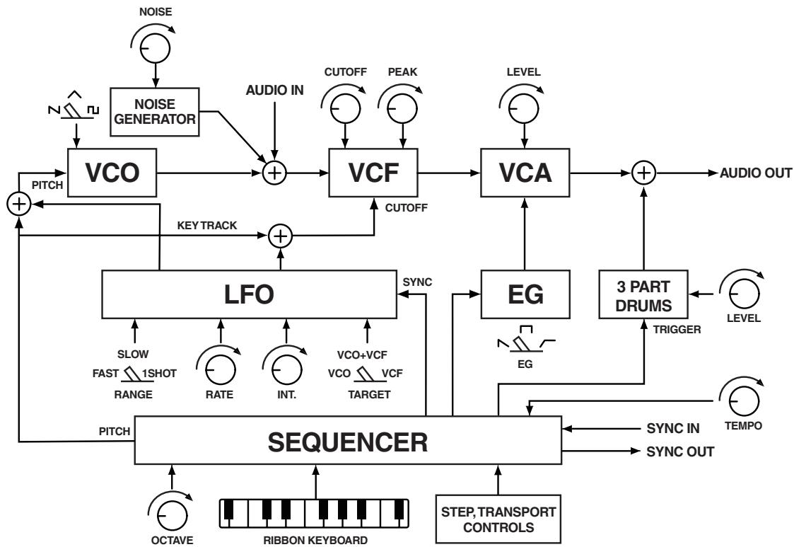
How the sound generator is structured
As shown in the block diagram (p.6), the synthesizer sound generator consists of an oscillator (VCO), filter (VCF), and amp (VCA). The synthesizer will produce sound when you touch the ribbon keyboard or play back sequence data. The drum sound generator provides three parts—bass drum (BD), snare (SN), and hi-hat (HH)—and is played back by sequence data.
The three elements of sound (pitch, timbre, and volume)
Sound has three basic elements: pitch, timbre (tonal character), and volume. Just like classic analog synthesizers of the past, the monotribe provides VCO, VCF, and VCA sections that let you control these elements. Edit the VCO to modify the pitch, the VCF to modify the timbre, and the VCA to modify the volume.
In addition, you can use the envelope generator (EG) and low frequency oscillator (LFO) to dynamically control parameters.
Block diagram
Getting started
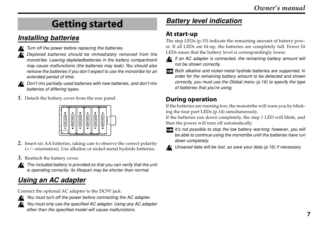
Installing batteries
Turn off the power before replacing the batteries.
Depleted batteries should be immediately removed from the monotribe. Leaving depletedbatteries in the battery compartment may cause malfunctions (the batteries may leak). You should also remove the batteries if you don't expect to use the monotribe for an extended period of time.
Don't mix partially-used batteries with new batteries, and don't mix batteries of differing types.
1. Detach the battery cover from the rear panel.
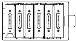
- Insert six AA batteries, taking care to observe the correct polarity (+/- orientation). Use alkaline or nickel-metal hydride batteries.
- Reattach the battery cover.
The included battery is provided so that you can verify that the unit is operating correctly; its lifespan may be shorter than normal.
Using an AC adapter
Connect the optional AC adapter to the DC9V jack.
You must turn off the power before connecting the AC adapter.
You must only use the specified AC adapter. Using any AC adapter other than the specified model will cause malfunctions.
Battery level indication
At start-up
The step LEDs (p.15) indicate the remaining amount of battery power. If all LEDs are lit-up, the batteries are completely full. Fewer lit LEDs mean that the battery level is correspondingly lower.
If an AC adapter is connected, the remaining battery amount will not be shown correctly.
Both alkaline and nickel-metal hydride batteries are supported. In order for the remaining battery amount to be detected and shown correctly, you must use the Global menu (p.16) to specify the type of batteries that you're using.
During operation
If the batteries are running low, the monotribe will warn you by blinking the four part LEDs (p.14) simultaneously.
If the batteries run down completely, the step 1 LED will blink, and then the power will turn off automatically.
Note It's not possible to stop the low battery warning; however, you will be able to continue using the monotribe until the batteries have run down completely.
Unsaved data will be lost, so save your data (p.16) if necessary.
Connections
The following illustration shows an example of typical connections. Connect your equipment as appropriate for your needs.
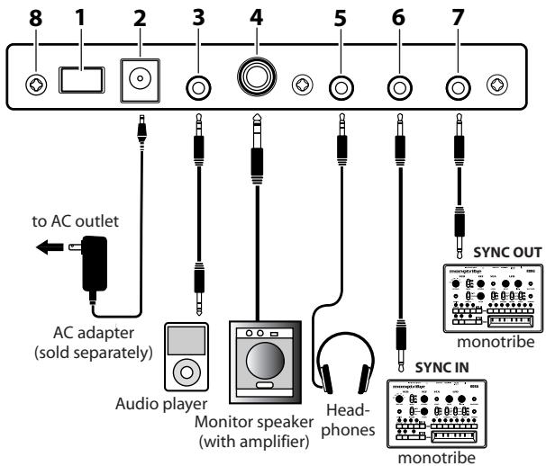

You must turn off the power before connecting anything. Careless usage may damage your speaker system or cause other malfunctions.
1. Power switch
This turns the power on/off. To turn the power off, press and hold the switch.
2. DC 9V jack
Connect the optional AC adapter here.
3.AUDIO IN jack
An external audio source connected to the AUDIO IN jack will be mixed with the VCO (p.11) and sent through the VCF (p.11) and VCA (p.11). You can use this to expand the monotribe's sonic possibilities, or use it as an effect processor for a separate audio source.

A signal input in stereo will be mixed to mono.
4. OUTPUT jack
Connect the monotribe's OUTPUT jack to the INPUT jack of your mixer or powered monitor speakers. The output signal is monaural, but the jack will accept either monaural phone plugs or stereo phone plugs (unbalanced).
5. HEADPHONES jack
Connect your headphones (stereo mini-plug) here.
6. SYNC OUT jack
This jack outputs a 5V pulse of 15ms at the beginning of each step. You can use this to synchronize another monotribe or other compatible equipment such as an analog sequencer to this monotribe unit. A Global menu setting (p.16) lets you specify the polarity of the pulse.
7.SYNC IN jack
If the SYNC IN jack is connected, the internal step clock will be ignored, and the sequencer will proceed through its steps according to the pulses that are input to this jack. You can use this jack to synchronize the monotribe's steps with pulses that are output from another monotribe unit, your analog sequencer or the audio output of a DAW. A Global menu setting (p.16) lets you specify the polarity of the pulses that are detected.
8. Grounding Screw
Use this screw to ground the unit. To do so, loosen the screw and attach a grounding wire.

Do not use the unit if the screw is removed.

Depending on how the unit is connected to other devices, you may feel a slight electrical stimulation if a soft part of your skin touches a connected microphone or the metal part of the unit.
This is caused by a very weak current that is harmless to humans. If this bothers you, use this grounding screw to ground the unit externally.
Turning the power on

Before you turn on the monotribe, you must turn off the power of your powered monitors or any other external output system.
- Turn the monotribe's LEVEL knob (p.11) and RHYTHM knob (p.15) all the way to the left.
-
Press the monotribe's power switch (p.8) to turn the power on. The step LEDs (p.15) will indicate the remaining amount of battery power.
-
Lower the volume controls of your powered monitors or external output system, and then turn their power on.
- Turn the monotribe's LEVEL knob and RHYTHM knob clockwise to an appropriate level.
- Adjust the volume of your external output system.
Turning the power off
-
Lower the volume of your powered monitors or external output system, and turn their power off.
-
Turn the monotribe's LEVEL knob (p.11) and RHYTHM knob (p.15) all the way to the left, and hold down the power switch until any lit LEDs have gone dark.

Never turn off the monotribe while global data (p.16) is being written. Doing so may damage the internal data.
Auto power-off
The monotribe has an auto power-off function. This function automatically turns the power off after approximately four hours have passed since the monotribe last produced sound.
Disabling the auto power-off function
If desired, you can disable the auto power-off function.
For details on this procedure, refer to the Global menu (p.16).
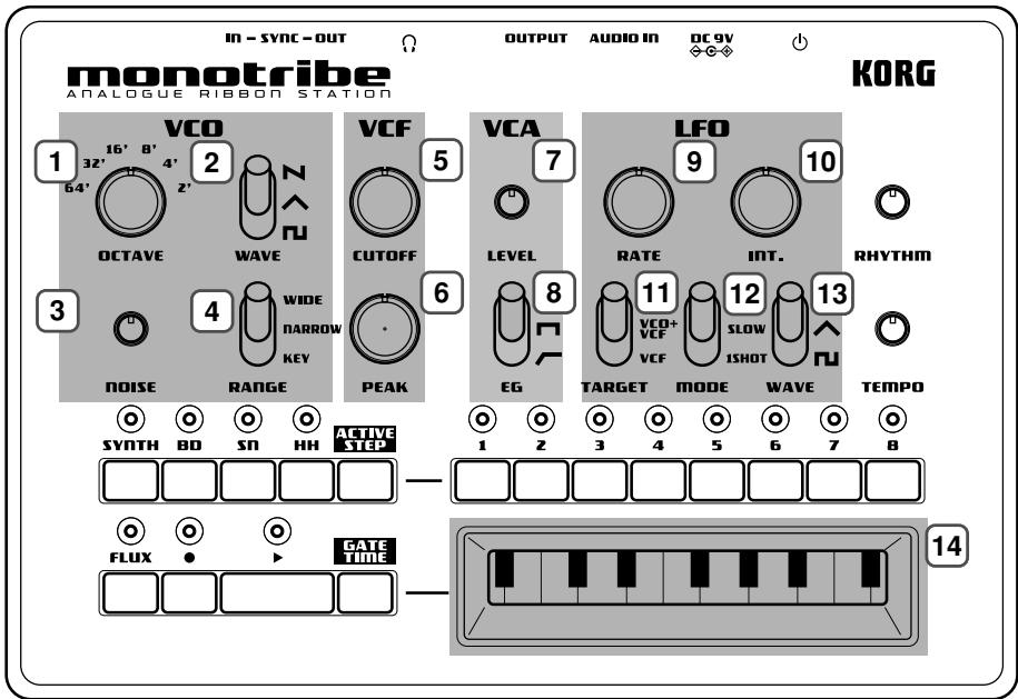
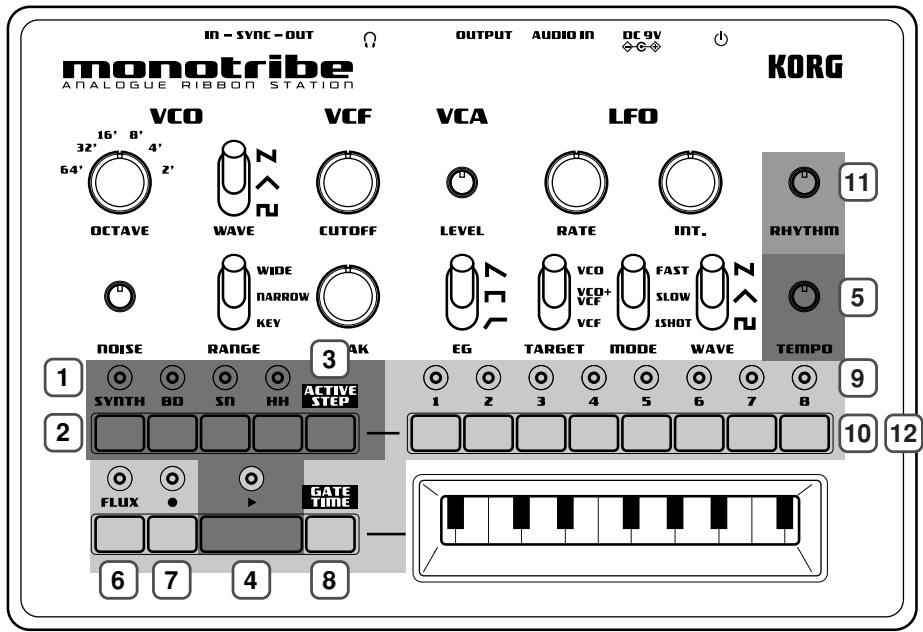
Panel description and functions
Synthesizer section
VCO (Voltage Controlled Oscillator)
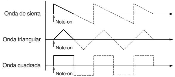
The oscillator generates the waveform that's the basis of the sound: a sawtooth wave, triangle wave, or square wave. The noise generator produces white noise. If an external audio source is connected to the AUDIO IN jack, it will be mixed with the VCO's output. The VCO generates a waveform at a pitch that's determined by the position being touched on the ribbon keyboard or by performance data that you've recorded as a sequence. In addition, the LFO can also apply time-varying changes to the pitch.
1. OCTAVE selector
This specifies the VCO pitch in steps of an octave. With the "64" setting, the pitch range of the ribbon keyboard will be A0-D2.
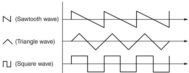
2.WAVE select switch
This selects the VCO waveform: sawtooth, triangle, or square.
3.NOISE knob
This knob adjusts the level of white noise that's mixed with the VCO output.
4. RANGE select switch
This specifies the ribbon keyboard's playing mode.
| WIDE | The pitch range will be extended to approximately six times that of the NARROW setting; pitch change will be continuous. The OCTAVE selector will be ignored. |
| NARROW | The pitch will change continuously according to the printed ribbon keyboard. |
| KEY | The pitch will change in chromatic steps according to the printed ribbon keyboard. |
VCF (Voltage Controlled Filter)
The filter modifies the timbre (tonal character) by boosting or cutting specific frequency regions of the sound produced by the oscillator. The monotribe uses the traditional 12 dB/oct low-pass filter (LPF) that was also used on the Korg MS-20. The character of the sound will change significantly depending on the settings of this filter. In addition, you can use the LFO to modulate the filter's cutoff frequency over time.
5.CUTOFF knob
This adjusts the cutoff frequency of the VCF, affecting the brightness of the sound.
Turning the knob toward the left will darken the sound, and turning the knob toward the right will brighten the sound.
6. PEAK knob
This adjusts the resonance of the VCF, adding emphasis to the cutoff frequency.
VCA (Voltage Controlled Amplifier)
The amp varies the volume of the sound. You can use the EG to make the volume change over time.
7. LEVEL knob
This adjusts the volume.
8. EG select switch
This lets you choose one of three modulation waveforms for the EG that's applied to the VCA.
N (DECAY) The volume will start at maximum the instant the note is sounded, and will then decay.
The volume will remain at maximum while the note is played.
(ATTACK) The volume will begin increasing the instant the note is sounded, and will remain at maximum while the note is played.
LFO (Low Frequency Oscillator)
The LFO applies cyclical changes to the parameters that determine the sound. You have three choices to specify which parameters will be modulated. Since the modulation rate can be adjusted over a broad range, you can use this to create everything from vibrato to sound effects. You can also use 1SHOT mode to make the LFO behave like an EG.
9.RATE knob
This adjusts the speed of modulation. Turning the knob toward the right produces faster modulation.
10.INT.knob
This adjusts the intensity (depth) of modulation. If you turn the knob all the way to the left, no modulation will be applied.
11. TARGET select switch
This specifies what will be affected by LFO modulation.
VCO The VCO pitch will change.
VCO+VCF The VCO pitch and the VCF cutoff frequency will change.
VCF The VCF cutoff frequency will change.
12.MODE select switch
This switches the range of the modulation rate, or changes how modulation is applied.
FAST The modulation rate will have a range of approximately 1Hz to 5kHz .
SLOW The modulation rate will have a range of approximately 0.05Hz to 18Hz .
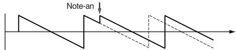
1SHOT When the note begins, the first half-cycle of modulation will be applied, and then the LFO will stop.
NOTE KEY SYNC is applied if you select FAST or 1SHOT.
A note played with 1SHOT
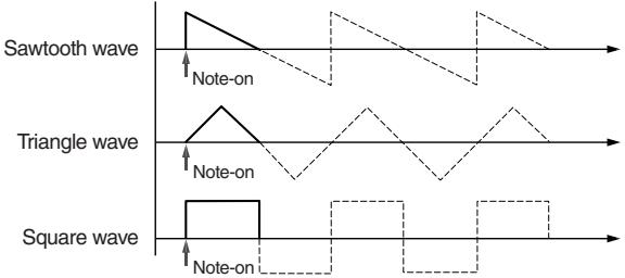
About KEY SYNC
Key Sync is a function that resets the phase of the LFO waveform when a note is played.
13.WAVE select switch
This selects the modulation waveform: sawtooth wave, triangle wave, or square wave. (p.11)
Keyboard
14. Ribbon keyboard
Touch this with your finger to play sounds.
Sequencer section
The monotribe contains an eight-step sequencer that controls the synthesizer and drum sound generator.
Basic controls
1. PART LEDs
These will light-up when you press a PART button to select a part.
2.PART buttons
Press these buttons to select the part to be edited.
SYNTH button
Press this button when you want to edit the SYNTH (synthesizer) part. The SYNTH part LED will light-up when you press the button.
BD button
Press this button when you want to edit the BD (bass drum) part. The BD part LED will light-up when you press the button.
SN button
Press this button when you want to edit the SN (snare drum) part. The SN part LED will light-up when you press the button.
HH button
Press this button when you want to edit the HH (hi-hat) part. The HH part LED will light-up when you press the button.
The part LEDs will blink when the batteries run low. For details, refer to "Battery level indication" (p.7).
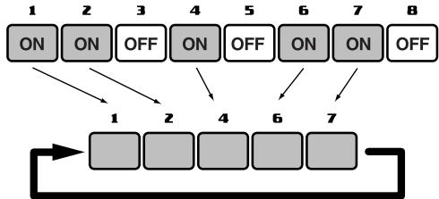
3. ACTIVE STEP button
Use this button to turn each step of the sequence on (enabled) or off (disabled).
While this button is pressed, the LED of each enabled step will light-up. To turn a step on/off, hold down the ACTIVE STEP button and press the desired step button. Steps that are turned off are disabled and will be skipped during playback and recording.
When you turn on the power, all steps are turned on.
It's not possible to turn all steps off at the same time.
4. PLAY button
Press this button to play or stop the sequence. Playback always starts from the beginning of the sequence. The PLAY LED will be lit during playback.
5. TEMPO knob
This knob sets the speed of the sequencer.
The range of this knob can be changed in the Global menu (p.16).
With the NARROW setting, you can make detailed adjustments to the tempo in a range of 60-180BPM. With the WIDE setting, you can adjust the tempo in a range of 10-600BPM.
The TEMPO knob is disabled if the SYNC IN jack is connected.
The numerical tempo values listed above refer to when each step is considered a 16th note.
Synthesizer sequence controls
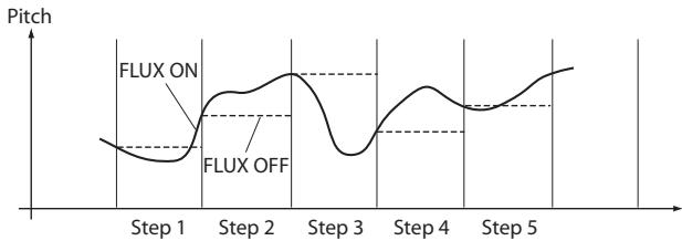
6.FLUX button
This button turns FLUX mode on/off.
ON The sequence of the synth part will be recorded and played back as continuous data.
OFF One note will play back for each step.
Note Turning this off might result in unexpected playback pitches depending on the performance's timing.
7. REC button
Pressing this button during playback will put the monotribe in record mode; the REC LED will light-up. When you play the ribbon keyboard, the data of your performance will be recorded.
Pressing this button while stopped will put the monotribe in record-ready mode; the REC LED will blink. In this state, pressing the PLAY button to start playback will activate record mode.
To exit record mode or record-ready mode, press the REC button once again to make the REC LED go dark.
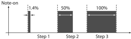
8. GATE TIME button
By holding down this button and using the ribbon keyboard while a sequence plays back, you can change the gate time (duration) of the synth part's notes; the change in gate time corresponds to the position where you touch the ribbon keyboard.
The gate time will be the minimum value (1.4%) at the far left of the ribbon keyboard, and the maximum value (100%) at the far right. By performing this operation in REC mode, the gate time for each step can be recorded in the sequence to occur during playback.
9. STEP LEDs
These LEDs will light-up or go dark when you press the corresponding step button. While a sequence plays back, the LEDs will blink to indicate the current step.
10. STEP buttons
These buttons turn each step on/off.
ON The step will be played and its step LED will light-up.
OFF The step will not be played and its step LED will not light-up.
Note If you record on a step that is turned off, it will automatically turn on. If you do this, any data previously recorded in that step will be erased.
Drum sound generator sequence controls
11. RHYTHM knob
This knob adjusts the volume of the drum sound generator.
12. STEP buttons
These buttons turn each step of the selected drum part (BD, SN, HH) on/off.
ON The step will be played and its step LED will light-up.
OFF The step will not be played and its step LED will not light-up.
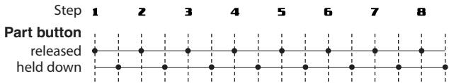
If you turn on a step button while holding down a part button, the part will sound half way through the step. This applies to each of the 8 step buttons, effectively providing 16 steps for the rhythm sequence.
Saving a sequence
When the sequencer is not playing back and the monotribe is not producing sound, hold down the REC button until the REC LED stops blinking and goes dark.
The saved sequence will be loaded at the next power-up. To change this, you'll need to adjust the settings located in the Global menu (p.16).

Never turn off the power while data is being saved. Doing so may destroy the internal data.

The saved settings are remembered even when the power is off.
Global menu
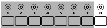
Here you can adjust various settings for the monotribe. These settings are assigned to step buttons 1-7 (see the table below).
| Step button 1 | Auto power-off |
| LED Unlit | Auto power-off is disabled. |
| * LED Lit | Auto power-off is enabled. |
| Step button 2 | Battery type selection |
| * LED Unlit | The monotribe is optimized for alkaline batteries. |
| LED Lit | The monotribe is optimized for nickel-metal hy- dride batteries. |
| Step button 3 | SYNC OUT polarity |
| * LED Unlit | The output will rise at the beginning of each step. |
| LED Lit | The output will fall at the beginning of each step. |
| Step button 4 | SYNC IN polarity |
| * LED Unlit | The step will advance when the input signal rises. |
| LED Lit | The step will advance when the input signal falls. |
| Step button 5 Sequence settings at start-up | |
| LED Unlit | The initial sequence will be loaded at power-on. |
| LED Blinking | The saved sequence will be loaded at power-on. |
| * LED Lit | The demo sequence will be loaded at power-on. |
| Step button 6 Drum preview | |
| LED Unlit | Nothing will sound when you press one of the drum sound generator part buttons. |
| * LED Lit | The corresponding drum sound will be heard when you press one of the drum sound generator part buttons. |
| Step button 7 TEMPO knob range | |
| LED Unlit | The TEMPO range will be narrow. |
| * LED Lit | The TEMPO range will be wide. |
- indicates the factory default setting.
Setting procedure
Press the corresponding step button to make the setting.
- While holding down the ACTIVE STEP button and the GATE TIME button, turn the power on. The monotribe will enter Global Menu mode.
-
Press the step button for the setting that you want to change. The LED will indicate the setting.
-
When you've finished adjusting settings, press the REC button to save the changes and start up the monotribe in its normal state. If you decide to cancel, press the FLUX button. The changes will be discarded, and the monotribe will start up in its normal state.

Never turn off the power while data is being saved. Doing so may destroy the internal data.

The saved settings are remembered even when the power is off.
Specifications
| Operating temperature | 0-+40°C (non-condensing conditions) |
| Keyboard | Ribbon keyboard |
| Sound generator | Analog synthesis 1VCO (saw, triangle, square), noise gen- erator, 1VCF (12dB/oct LPF), 1VCA, 1LFO |
| Drum | 3 parts, discrete analog |
| Sequencer | 8 steps |
| Connectors | |
| AUDIO IN jack | Ø3.5mm stereo mini-phone jack |
| OUTPUT jack | Ø6.3mm stereo phone jack (unbalanced) |
| HEADPHONES jack | Ø3.5mm stereo mini-phone jack |
| SYNC IN jack | Ø3.5mm monaural mini-phone jack |
| Maximum input level | 20V |
| SYNC OUT jack | Ø3.5mm monaural mini-phone jack |
| Output level | 5V |
| Power supply | "AA/LR6" alkaline battery x6 or AA nickel-metal hydride battery x6 Optional AC adapter (DC9V ◆-●-●) |
Battery life
approximately 14 hours (when using alkaline batteries)
Dimensions (W× D× H)
207 × 145 × 70 ~mm / 8.15 × 5.71 × 2.76 inches
Weight
735g / 1.62 lbs. (excluding batteries)
Included items
Six AA alkaline batteries for verifying operation, owner's manual
- Specifications and appearance are subject to change without notice for improvement.
Section sequencer 28
Menu Global 31
VCO ('Voltage Controlled Oscillator')
VCF ('Voltage Controlled Filter')
VCA ('Voltage Controlled Amplifier')
LFO ('Low Frequency Oscillator')
VCO (Voltage Controlled Oscillator)
VCF (Voltage Controlled Filter)
VCA (Voltage Controlled Amplifier)
LFO (Low Frequency Oscillator)
3.ACTIVE STEP-Taster
VCO (Voltage Controlled Oscillator)
VCF (Voltage Controlled Filter)
VCA (Voltage Controlled Amplifier)
LFO (Low Frequency Oscillator)
Notareproducedacon1SHOT
Acerca de KEY SYNC

- Precautions
- Location
- Power supply
- Interference with other electrical devices
- Handling
- Care
- Keep this manual
- Keeping foreign matter out of your equipment
- Notice regarding disposal (EU only)
- THE FCC REGULATION WARNING (for USA)
- IMPORTANT NOTICE TO CONSUMERS
- Main features
- Analog synthesis
- Self-tuning function
- Ribbon keyboard
- Analog drum sound generator
- Eight-step sequencer
- FLUX mode
- Multi-function LFO
- External input jack
- Internal speaker
- AC adapter or battery power
- How the sound generator is structured
- The three elements of sound (pitch, timbre, and volume)
- Block diagram
- Getting started
- Installing batteries
- Using an AC adapter
- Battery level indication
- At start-up
- During operation
- Connections
- Power switch
- DC 9V jack
- 3.AUDIO IN jack
- OUTPUT jack
- HEADPHONES jack
- SYNC OUT jack
- 7.SYNC IN jack
- Grounding Screw
- Turning the power on
- Turning the power off
- Auto power-off
- Disabling the auto power-off function
- Panel description and functions
- Synthesizer section
- VCO (Voltage Controlled Oscillator)
- OCTAVE selector
- 2.WAVE select switch
- 3.NOISE knob
- RANGE select switch
- VCF (Voltage Controlled Filter)
- 5.CUTOFF knob
- PEAK knob
- VCA (Voltage Controlled Amplifier)
- LEVEL knob
- EG select switch
- LFO (Low Frequency Oscillator)
- 9.RATE knob
- 10.INT.knob
- TARGET select switch
- 12.MODE select switch
- About KEY SYNC
- 13.WAVE select switch
- Keyboard
- Ribbon keyboard
- Sequencer section
- Basic controls
- PART LEDs
- 2.PART buttons
- SYNTH button
- BD button
- SN button
- HH button
- ACTIVE STEP button
- PLAY button
- TEMPO knob
- Synthesizer sequence controls
- 6.FLUX button
- REC button
- GATE TIME button
- STEP LEDs
- STEP buttons
- Drum sound generator sequence controls
- RHYTHM knob
- STEP buttons
- Saving a sequence
- Global menu
- Setting procedure
- Specifications
- Battery life
- Dimensions (W× D× H)
- Weight
- Included items
- VCO ('Voltage Controlled Oscillator')
- VCF ('Voltage Controlled Filter')
- VCA ('Voltage Controlled Amplifier')
- LFO ('Low Frequency Oscillator')
- 3.ACTIVE STEP-Taster
- Acerca de KEY SYNC
Brand : KORG
Model : MONOTRIBE
Category : Analog synthesizer